WO2011045915A1 - 衣類乾燥機および洗濯乾燥機 - Google Patents
衣類乾燥機および洗濯乾燥機 Download PDFInfo
- Publication number
- WO2011045915A1 WO2011045915A1 PCT/JP2010/006034 JP2010006034W WO2011045915A1 WO 2011045915 A1 WO2011045915 A1 WO 2011045915A1 JP 2010006034 W JP2010006034 W JP 2010006034W WO 2011045915 A1 WO2011045915 A1 WO 2011045915A1
- Authority
- WO
- WIPO (PCT)
- Prior art keywords
- drying
- air
- temperature
- unit
- air path
- Prior art date
- Legal status (The legal status is an assumption and is not a legal conclusion. Google has not performed a legal analysis and makes no representation as to the accuracy of the status listed.)
- Ceased
Links
Images


Classifications
-
- D—TEXTILES; PAPER
- D06—TREATMENT OF TEXTILES OR THE LIKE; LAUNDERING; FLEXIBLE MATERIALS NOT OTHERWISE PROVIDED FOR
- D06F—LAUNDERING, DRYING, IRONING, PRESSING OR FOLDING TEXTILE ARTICLES
- D06F25/00—Washing machines with receptacles, e.g. perforated, having a rotary movement, e.g. oscillatory movement, the receptacle serving both for washing and for centrifugally separating water from the laundry and having further drying means, e.g. using hot air
-
- D—TEXTILES; PAPER
- D06—TREATMENT OF TEXTILES OR THE LIKE; LAUNDERING; FLEXIBLE MATERIALS NOT OTHERWISE PROVIDED FOR
- D06F—LAUNDERING, DRYING, IRONING, PRESSING OR FOLDING TEXTILE ARTICLES
- D06F2103/00—Parameters monitored or detected for the control of domestic laundry washing machines, washer-dryers or laundry dryers
- D06F2103/02—Characteristics of laundry or load
- D06F2103/04—Quantity, e.g. weight or variation of weight
-
- D—TEXTILES; PAPER
- D06—TREATMENT OF TEXTILES OR THE LIKE; LAUNDERING; FLEXIBLE MATERIALS NOT OTHERWISE PROVIDED FOR
- D06F—LAUNDERING, DRYING, IRONING, PRESSING OR FOLDING TEXTILE ARTICLES
- D06F2103/00—Parameters monitored or detected for the control of domestic laundry washing machines, washer-dryers or laundry dryers
- D06F2103/02—Characteristics of laundry or load
- D06F2103/08—Humidity
-
- D—TEXTILES; PAPER
- D06—TREATMENT OF TEXTILES OR THE LIKE; LAUNDERING; FLEXIBLE MATERIALS NOT OTHERWISE PROVIDED FOR
- D06F—LAUNDERING, DRYING, IRONING, PRESSING OR FOLDING TEXTILE ARTICLES
- D06F2103/00—Parameters monitored or detected for the control of domestic laundry washing machines, washer-dryers or laundry dryers
- D06F2103/28—Air properties
- D06F2103/32—Temperature
-
- D—TEXTILES; PAPER
- D06—TREATMENT OF TEXTILES OR THE LIKE; LAUNDERING; FLEXIBLE MATERIALS NOT OTHERWISE PROVIDED FOR
- D06F—LAUNDERING, DRYING, IRONING, PRESSING OR FOLDING TEXTILE ARTICLES
- D06F2103/00—Parameters monitored or detected for the control of domestic laundry washing machines, washer-dryers or laundry dryers
- D06F2103/28—Air properties
- D06F2103/36—Flow or velocity
-
- D—TEXTILES; PAPER
- D06—TREATMENT OF TEXTILES OR THE LIKE; LAUNDERING; FLEXIBLE MATERIALS NOT OTHERWISE PROVIDED FOR
- D06F—LAUNDERING, DRYING, IRONING, PRESSING OR FOLDING TEXTILE ARTICLES
- D06F2105/00—Systems or parameters controlled or affected by the control systems of washing machines, washer-dryers or laundry dryers
- D06F2105/16—Air properties
- D06F2105/24—Flow or velocity
-
- D—TEXTILES; PAPER
- D06—TREATMENT OF TEXTILES OR THE LIKE; LAUNDERING; FLEXIBLE MATERIALS NOT OTHERWISE PROVIDED FOR
- D06F—LAUNDERING, DRYING, IRONING, PRESSING OR FOLDING TEXTILE ARTICLES
- D06F58/00—Domestic laundry dryers
- D06F58/02—Domestic laundry dryers having dryer drums rotating about a horizontal axis
-
- D—TEXTILES; PAPER
- D06—TREATMENT OF TEXTILES OR THE LIKE; LAUNDERING; FLEXIBLE MATERIALS NOT OTHERWISE PROVIDED FOR
- D06F—LAUNDERING, DRYING, IRONING, PRESSING OR FOLDING TEXTILE ARTICLES
- D06F58/00—Domestic laundry dryers
- D06F58/32—Control of operations performed in domestic laundry dryers
- D06F58/34—Control of operations performed in domestic laundry dryers characterised by the purpose or target of the control
- D06F58/36—Control of operational steps, e.g. for optimisation or improvement of operational steps depending on the condition of the laundry
- D06F58/38—Control of operational steps, e.g. for optimisation or improvement of operational steps depending on the condition of the laundry of drying, e.g. to achieve the target humidity
Definitions
- the present invention relates to a clothes dryer for drying clothes and a washing dryer having a washing function and a clothes drying function.
- drum-type clothes dryers and washing dryers blow drying air into the drum through the air passage, and the drying air is brought into contact with the clothes put in the drum to remove moisture from the clothes and dry the clothes.
- the drying air that has become humid due to moisture is discharged to the air path outside the drum.
- the clothes are dried in a limited space of a narrow drum, there is a problem that the clothes after drying are in a state of strong wrinkles, and various methods have been considered for solving the problem. (For example, refer to Patent Document 1).
- FIG. 11 shows a conventional drum-type washing and drying machine described in Patent Document 1.
- the air volume is reduced by blowing drying air from the first air passage 121 and the second air passage 122 into the rotary drum 123 during the drying process. Increased, the evaporation of moisture from the clothes 124 is promoted to shorten the drying time.
- high-pressure air is blown to the clothes 124 in the rotary drum 123 at a high speed from a second blowing port 125 provided at the lower part of the opening of the rotary drum 123. In this way, by stirring while lifting the garment 124 with the blown air, wrinkles are prevented from being generated in the garment 124, thereby improving the dry finish.
- the conventional configuration high-pressure and high-speed air is blown onto the garment 124.
- the work amount is increased by that amount.
- the power consumption increases.
- two motors for the blower fan are used to increase the amount of air blown into the rotary drum 123, and the power consumption is further increased. Therefore, the conventional drum-type washing / drying machine has a problem in terms of reducing power consumption as a configuration for shortening drying time and extending wrinkles.
- An object of the present invention is to provide a clothes dryer and a washing dryer capable of drying with low power consumption and low wrinkles.
- a clothes dryer includes a housing portion that houses clothes to be dried, a first air passage that has a first air outlet that opens in the housing portion, and the first opening that opens in the housing portion.
- a second air passage having a second air outlet having a smaller air passage cross-sectional area than the air outlet, an air passage switching unit that selectively switches between the first air passage and the second air passage, and the first air passage
- the second air path is selected, a larger amount of drying air is blown from the first air outlet into the housing portion than when the second air path is selected, while the second air path is selected.
- Exhaust temperature detection unit for detecting the temperature of the drying air discharged from the housing unit The controls the air path switching unit based on the discharge temperature detector of the detection result, and a selectively switching control unit and the said first air passage second air passage in the course of the drying process.
- the power consumption of the blower can be reduced, a clothes dryer and a washing dryer that can be dried with low power consumption and less wrinkles can be realized.
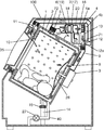
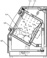
- FIG. 1 is a side sectional view of a drum-type washing and drying machine according to an embodiment of the present invention.
- a cylindrical drum 1 (accommodating portion) having a bottom surface with a front opening for accommodating laundry is supported in a casing 100 and enclosed in a cylindrical aquarium 2 for storing washing water.
- a drum drive motor 3 (drum drive unit) is attached to the rear surface of the water tank 2 so as to rotate the drum 1 by tilting the rotating shaft forward.
- the casing 100 is provided with a door body 35 facing the opening end side of the drum 1, and the user opens and closes the laundry body (clothing) with respect to the drum 1 by opening the door body 35. be able to.
- a water supply pipe provided with a water supply valve (not shown) and a drain pipe 40 provided with a drain valve 27 are connected to the water tank 2.
- the drying air for drying the clothes is blown to the blower 4 to take moisture from the laundry in the drum 1 to become a humid state, and passes through the discharge port 5 located around the side surface of the drum 1 to the drum. 1 is discharged to the outside.
- the discharged drying air is dehumidified by the dehumidifying unit 6.
- the drying air dehumidified by the dehumidifying unit 6 is heated by the heating unit 7.
- the heated drying air is guided to either the first air passage 9 or the second air passage 11 and blows out into the drum 1 again.
- the first air passage 9 has a first air outlet 8 opened to the rear of the drum 1.
- the second air passage 11 has a second air outlet 10 opened on the front peripheral side surface of the drum 1.
- the first air outlet 8 of the first air passage 9 is formed so as to have an air passage cross-sectional area larger than that of the second air outlet 10, and there is less pressure loss than the second air passage 11, and a large air volume is dried.
- the working air can be blown into the drum 1.
- the second air outlet 10 of the second air passage 11 has an air passage cross-sectional area smaller than that of the first air outlet 8, and high-pressure and high-speed drying air in the drum 1 as compared with the first air outlet 8. Can be blown out.
- the gap between the front of the rotating drum 1 and the water tank 2 is formed as small as possible so that clothes are not caught. Therefore, although it is difficult in terms of space to provide a small opening with a small opening and a small pressure loss in the small gap, the second blowing outlet 10 that blows off high-pressure and high-speed wind with a relatively small air passage cross-sectional area is provided. It can be provided.
- the bottom of the back of the drum 1 has a space for providing the first air outlet 8 having a relatively large opening.
- both small clothes and long clothes can be efficiently dried. Especially, small clothes can be dried with relatively little wrinkles.
- long clothes that are likely to be twisted and wrinkle easily due to agitation during drying are liable to be biased to the front of the drum 1, and therefore wind (drying air) is discharged from the second air outlet 10 located in front of the drum 1. ) Is faster to dry.
- wind drying air
- the long clothing is easily spread and the long clothing moves well by the wind, so that the effect of reducing wrinkles is great. .
- the air path switching unit 12 is provided at a branch portion between the first air path 9 and the second air path 11 formed on the downstream side of the air blowing unit 4.
- the air path switching unit 12 switches the passage of drying air to either the first air path 9 or the second air path 11.
- the air path switching unit 12 includes a valve 12a pivotally supported by a branch portion between the first air path 9 and the second air path 11, and a drive unit (not shown) that rotationally drives the valve 12a. To do. Then, when the valve 12a rotates to the a side in FIG. 1 and closes the second air passage 11, the first air passage 9 side is opened, and the drying air blown by the blower unit 4 is supplied to the first air passage 9. To go through. On the other hand, when the valve 12a rotates to the b side in the figure and closes the first air passage 9, the second air passage 11 side is opened, and the drying air blown by the blower 4 is supplied to the second air passage 11. To go through.
- the circulation air passage 13 is provided with the air blowing section 4 and the air passage switching section 12 in the middle thereof, and passes through the air passage of the drum 1, the discharge port 5, the dehumidifying section 6, and the heating section 7 in this order, and again Drying air is sent from the first air outlet 8 or the second air outlet 10 to the drum 1, and the air for drying is circulated in the drum type laundry dryer.
- the blower unit 4 is provided between the heating unit 7 and the air path switching unit 12, and sends the drying air heated by the heating unit 7 to the downstream side of the circulation air path 13.
- the blower unit 4 includes a blower fan 4a and a blower fan motor 4b.
- the air blowing unit 4 when the air path switching unit 12 switches to the first air path 9, the air volume passing through the first air path 9 becomes a predetermined air volume larger than the air volume of the second air path 11.
- the blower fan 4a is rotated.
- the wind speed passing through the second air outlet 10 of the second air path 11 becomes a predetermined air speed that is faster than the air speed passing through the first air outlet 8.
- the fan 4a for ventilation is rotated so that it may become.
- the wind speed passing through the first air outlet 8 can be set to about 10 m / s, and the wind speed passing through the second air outlet 10 can be set to 50 m / s or more.
- the wind speed which passes the 1st blower outlet 8 and the 2nd blower outlet 10 is not limited to this, Arbitrary if the wind speed in the 2nd blower outlet 10 satisfy
- the amount of air passing through the first air passage 9 is larger than the amount of air passing through the second air passage 11, and passes through the second air outlet 10 of the second air passage 11.
- the wind speed is higher than the wind speed passing through the first air outlet 8, and the air path switching unit 12 is operated during the drying process to switch between the first air path 9 and the second air path 11.
- the discharge port 5 is disposed at a position relatively far from the first air outlet 8 than the distance from the second air outlet 10 (in other words, the discharge port 5 is relatively second. It is close to the air outlet 10 and far from the first air outlet 8). Therefore, the discharge port 5 is provided closer to the front than the rear of the drum 1.
- the outlet 5 may be provided in the vicinity of the second outlet 10 located in front of the drum 1 so that the distance from the first outlet 8 is the longest.
- the discharge port 5 is arranged on the upper side of the drum 1 so that the drying air after contacting the clothes can be effectively discharged upward.
- the discharge port 5 can be provided at a place other than above the drum 1.
- a drum-type laundry dryer since it is affected by washing water, It is preferable to provide it above.
- the second air outlet 10 opens at the upper front part of the drum 1. During ventilation from the second outlet 10, drying air with high pressure and high wind speed blows out from the second outlet 10 even if the exhaust outlet 5 is near the second outlet 10. The air can reach a position away from the exhaust port 5, and the effect of stretching wrinkles can be maintained without deteriorating the contact between the clothes and the drying air. As a result, high-pressure and high-speed drying air can be effectively sprayed on the clothing that is moved by the rotation of the drum 1 and the wrinkle reduction effect can be enhanced.
- a damper 14 that supports the aquarium 2 and attenuates the vibration of the aquarium 2 when the drum 1 is rotated in a weight unbalanced state caused by uneven clothing in the drum 1 during dehydration or the like. Is provided.
- the damper 14 is provided with a cloth amount detector 15 that detects the amount of clothing by detecting the amount of displacement of the shaft of the damper 14 up and down due to the weight change caused by the clothing in the water tank 2 to be supported.
- the drum type washing and drying machine of the present embodiment is configured to perform heat pump type dehumidification and heating, and includes a heat pump device.
- This heat pump device is decompressed by a compressor 16 that compresses the refrigerant, a radiator 17 that radiates heat of the refrigerant that has been compressed to a high temperature and a high pressure, and a throttle unit 18 that depressurizes the pressure of the high pressure refrigerant.
- a heat absorber 19 that draws heat from the surroundings by the low-pressure refrigerant and a pipe line 20 that connects these four members and circulates the refrigerant are provided. And the heat absorber 19 in this heat pump apparatus is said dehumidification part 6, and the heat radiator 17 is said heating part 7.
- the drum-type washing / drying machine is not limited to a structure that performs heat pump-type clothes drying.
- the dehumidifying unit 6 may be a water-cooling type in which water is sprayed directly on the drying air
- the heating unit 7 may be a heater.
- the drum type washing and drying machine includes an inflow temperature detection unit 71 such as a thermistor for detecting the temperature of the drying air flowing into the drum 1.
- the inflow temperature detection unit 71 is provided at or near a branch portion between the first air passage 9 and the second air passage 11 formed on the downstream side of the air blowing unit 4. Thereby, even when any one of the first air passage 9 and the second air passage 11 is used, the temperature of the drying air flowing into the drum 1 can be detected by one inflow temperature detecting portion 71. .
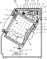
- the inflow temperature detection unit 71 instead of the inflow temperature detection unit 71, as shown in FIG. 2, the inflow temperature detection unit 71 a provided in the first air outlet 8 in the first air passage 9 or in the vicinity thereof and the second air passage 11 in the second air outlet 11. You may use the inflow temperature detection part 71b provided in the blower outlet 10 or its vicinity. In this case, although the two inflow 1st temperature detection parts 71a and 71b are required, the temperature of the drying air just before flowing in into the drum 1 can be detected correctly.
- the drum type washing and drying machine includes a discharge temperature detection unit 72 such as a thermistor for detecting the temperature of the drying air discharged from the drum 1 after coming into contact with clothes.
- the discharge temperature detector 72 is provided at or near the discharge port 5.
- the drum type washing and drying machine has a control unit 70.
- the control unit 70 controls a series of operation operations including washing, rinsing, dehydration, and drying based on setting information input from the user via the input setting unit 32 and operation state monitoring of each unit.
- the control unit 70 controls the rotation of the drum drive motor 3 via the motor drive circuit 22, controls the operation of the blower unit 4 and the heat pump device 50, and further includes an inflow temperature detection unit 71 and Based on the detection result of the discharge temperature detection unit 72, the air path switching unit 12 is controlled to switch between the first air path 9 and the second air path 11.
- the control unit 70 includes, for example, a CPU (Central Processing Unit) (not shown), a ROM (Read Only Memory) that stores programs, a RAM (Random Access Memory) that stores programs and data when various processes are executed, an input / output interface, and the like. Can be configured by a bus connecting the two.
- a CPU Central Processing Unit
- ROM Read Only Memory
- RAM Random Access Memory
- the 1st blower outlet 8 of the 1st air path 9 can also be made into multiple.
- the example which provided only the 2nd blower outlet 10 of the 2nd air path 11 is shown, the 2nd blower outlet 10 can also be made into two or more.
- the fibers can move freely when moisture is present in the fibers, so even if the clothes are stirred and bent by mechanical force by the rotation of the drum, the direction in which they are stretched next When force is applied, the bent part will not stretch and remain as wrinkles. Therefore, this period is a period in which wrinkles are unlikely to occur.
- the bonding strength between the cotton fibers becomes stronger and the movement of the fibers becomes worse.
- the fiber is bent by a mechanical force, the state is easily maintained. If the drying further proceeds and the moisture in the fiber is further reduced, the fiber remains bent and does not stretch even if a force is applied in the next stretching direction. This state is called wrinkle fixation.
- the period during which the bonding strength between the cotton fibers is strong is a period during which wrinkles are likely to occur.
- moisture In order to dry clothes that are easy to stick, moisture must be evaporated, but when moisture decreases, the conflicting phenomenon of wrinkles sticking occurs. The more wrinkles stick, the less dry the finish.
- the drying rate (%) is expressed by the following equation.
- Drying rate (weight of standard clothes / weight of clothes including moisture) x 100
- the mass of the standard clothing is the mass of the clothing balanced under the conditions of an air temperature of 20 ° C. and a humidity of 65%.
- the drying process is not targeted at 100% as the drying rate at the end of drying, but the drying process is completed at a drying rate that exceeds 100% (for example, a drying rate of 102% to 105%). Designed to do. Therefore, when the drying process is divided into regions based on the drying rate, wrinkles from the beginning of the drying in which the wrinkles from the immediately after dehydration to the drying rate of about 90% are difficult to be fixed, wrinkles from the drying rate of about 90% to about 100% are generated and fixed. In the middle part of the drying, where the amount of water is likely to increase, and in the final stage of the drying, where the drying rate exceeds 100% and wrinkles are unlikely to occur.
- a high-pressure and high-speed wind that is effective in reducing wrinkles by increasing the clothes is blown out from the second air outlet 10 of the second air passage 11 and applied to the clothes.
- a large amount of air is blown from the first air outlet 8 of the first air passage 9 in at least one region of the early drying stage and the final drying stage. In this way, by switching between the first air path 9 and the second air path 11 in the drying process, the generation of wrinkles is reduced and power saving is also achieved.
- the timing of the beginning of drying, the middle of drying, and the end of drying in the drying process can be determined based on the detection results of the discharge temperature detection unit 72 (or the detection results of the inflow temperature detection unit 71 and the discharge temperature detection unit 72). This will be described below.
- the preheating period, the constant rate drying period, and the decreasing rate drying period in the drying process will be described.
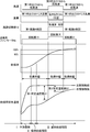
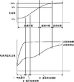
- the drying rate and drying air temperature during the drying process are: It changes as shown in FIG. 9 and is distinguished by three drying periods.
- I Preheating period” in which clothing is warmed by the heat of drying air, moisture is present on the surface of the clothing, and moisture constantly evaporates from the clothing surface, resulting in a constant reduction in the mass of wet clothing.
- II constant rate drying period”
- moisture on the surface of the garment disappears.
- the drying proceeds, and the drying rate (mass ratio of wet clothing in the middle of drying to the weight of clothing serving as a basis for the dried state) increases. Therefore, during the constant rate drying period, even if the temperature change of the drying air after coming into contact with the clothes is observed, the change in the drying rate during this time cannot be captured.
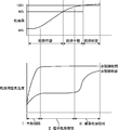
- the drying rate and drying air temperature during the drying process are shown in FIG. It changes as shown. That is, during the I preheating period, moisture on the clothing surface evaporates to some extent. And there is almost no constant rate drying period of II after that, the clothes surface is dried to some extent, and the movement of moisture from the inside cannot catch up, that is, the reduced rate drying period of III suddenly in a short time from the start of the drying process become. During this reduced rate drying period, the temperature of the drying air after coming into contact with the clothing gradually rises, so it is possible to estimate the progress of drying, that is, the drying rate of the clothing, by the change in the temperature of the drying air. It is.
- the control unit 70 detects the detection result of the discharge temperature detection unit 72 (or the inflow temperature detection unit 71 and the discharge temperature detection unit 72. Based on the detection result), the beginning of drying, the middle of drying, and the end of drying in the drying process are determined, and the air path switching unit 12 is controlled to switch between the first air path 9 and the second air path 11 in a timely manner. More specifically, after the drying process is started, the control unit 70 until the detection temperature of the discharge temperature detection unit 72 becomes equal to or higher than the first predetermined temperature (or the detection temperature of the inflow temperature detection unit 71 and the discharge temperature detection unit 72). Until the difference between the detected temperature and the detected temperature is within the first predetermined temperature).
- control unit 70 thereafter determines that the difference between the detection temperature of the inflow temperature detection unit 71 and the detection temperature of the discharge temperature detection unit 72 is not higher than the detection temperature of the discharge temperature detection unit 72 becomes equal to or higher than the second predetermined temperature.
- the period until the temperature falls within the second predetermined temperature is determined as the middle drying stage.
- control part 70 judges that the period until a drying process is complete
- the temperature of the drying air heated by the heating unit 7 (that is, the temperature of the drying air flowing into the drum 1) is substantially constant, based on only the detected temperature of the discharge temperature detecting unit 72, the beginning of drying and the middle of drying It is also possible to determine the end of the drying season. However, it is better to judge the timing of the beginning of drying, the middle of drying, and the end of drying based on the difference between the detected temperature of the inflow temperature detecting unit 71 and the detected temperature of the discharge temperature detecting unit 72. It is possible to make a highly accurate determination that follows even a slight temperature change.
- the drum type washing and drying machine of the present embodiment can achieve a good dry finish with less generation of wrinkles of clothes while saving power.
- the discharge port 5 is disposed at a position close to the second air outlet 10 in front of the drum 1 and far from the first air outlet 8.
- the distance between the first air outlet 8 and the exhaust port 5 becomes long, and air is being blown from the first air outlet 8 behind the drum 1.
- the drying air blown out from the first air outlet 8 spreads widely in the drum 1. Accordingly, the clothes and the drying air are efficiently in contact with each other in the drum 1, and the clothes can be dried with a small amount of power consumption.
- the second air outlet 10 is used for drying at high pressure and high wind speed. Since the air is blown out, the drying air can reach from the front of the drum 1 to the rear. Thereby, the contact between the drying air and the clothes does not deteriorate, and the effect of stretching the wrinkles with the high-pressure and high-winding drying air can be maintained.
- FIG. 4 is a time chart showing an example of the airway switching timing. The operation of the drum type washer / dryer when the first air path switching timing shown in the figure is applied will be described below.
- the air passage cross-sectional area is large and the pressure loss is large in the initial drying period from the start of the drying operation until the temperature difference between the drying air before and after contact with the clothing reaches the first predetermined temperature difference.
- a small first air passage 9 is used, and a large amount of drying air is blown out from the first air outlet 8 at the rear of the drum 1 and applied to the clothes. That is, the control unit 70 controls the air path switching unit 12 to open the first air path 9 side, and starts the drying operation. And the control part 70 continues the open state of the 1st air path 9 until the detection temperature of the inflow temperature detection part 71 and the detection temperature of the discharge
- the air path switching unit 12 switches to the second air path 11.
- the rotational speed of the blower fan motor 4b is increased.
- the control unit 70 controls the air path switching unit 12 to control the second air path 11 when the detected temperature of the inflow temperature detecting unit 71 and the detected temperature of the discharge temperature detecting unit 72 become the first predetermined temperature difference.
- the ventilation part 4 While opening a side, the ventilation part 4 is controlled and the rotation speed of the motor 4b for ventilation fans is raised. Then, the control part 70 continues the open state of the 2nd air path 11 until the completion
- the total amount of power consumption is less than the case where the high-speed and high-speed drying air is always blown out and the two blower fan motors are always used to further increase the air volume. A good dry finish with less wrinkles can be realized.
- FIG. 5 is a time chart showing another example of the airway switching timing. The operation of the drum type washer / dryer when the second air path switching timing shown in the figure is applied will be described below.
- the second air path is used in the initial drying period and the intermediate drying period until the temperature difference between the drying air before and after contact with the clothing reaches the second predetermined temperature difference in the drying process.
- 11 is used to blow high-pressure and high-speed drying air obtained by rotating the blower fan motor 4b at a high rotational speed from the second blower outlet 10 having a small air passage cross-sectional area near the blower outlet, and hit the clothes.
- the control unit 70 controls the air path switching unit 12 to open the second air path 11 side, and starts the drying operation.
- the control part 70 continues the open state of the 2nd air path 11 until the detection temperature of the inflow temperature detection part 71 and the detection temperature of the discharge
- the air path switching unit 12 switches to the first air path 9 at the end of drying after the temperature difference between the drying air before and after contact with the clothing reaches the second predetermined temperature difference.
- the amount of moisture contained in the clothes is small, and it takes time for this little moisture to come into contact with the drying air and evaporate. In such a state, it is necessary to increase the chance that moisture and the drying air come into contact with each other by blowing a large amount of drying air into the drum 1, and a large amount of air can be obtained with low power consumption. preferable.
- the control unit 70 controls the air path switching unit 12 to control the first air path 9 when the detected temperature of the inflow temperature detecting unit 71 and the detected temperature of the discharge temperature detecting unit 72 become the second predetermined temperature difference. While opening a side, the ventilation part 4 is controlled and the rotation speed of the motor 4b for ventilation fans is reduced. Then, the control part 70 continues the open state of the 1st air path 9 until completion
- the total amount of power consumption is less than the case where the high-speed and high-speed drying air is always blown out and the two blower fan motors are always used to further increase the air volume. A good dry finish with less wrinkles can be realized.
- FIG. 6 is a time chart showing another example of the airway switching timing. The operation of the drum type washer / dryer when the third air path switching timing shown in FIG.
- the air passage cross-sectional area is large and the pressure loss is large in the initial drying period from the start of the drying operation until the temperature difference between the drying air before and after contact with the clothing reaches the first predetermined temperature difference.
- a small first air passage 9 is used, and a large amount of drying air is blown out from the first air outlet 8 at the rear of the drum 1 and applied to the clothes. That is, the control unit 70 controls the air path switching unit 12 to open the first air path 9 side, and starts the drying operation. And the control part 70 continues the open state of the 1st air path 9 until the detection temperature of the inflow temperature detection part 71 and the detection temperature of the discharge
- the air path switching unit 12 switches to the second air path 11 and Increase the rotational speed of the motor 4b.
- high-pressure and high-speed drying air obtained by rotating the blower fan motor 4b at a large number of revolutions from the second outlet 10 having a smaller air passage cross-sectional area than the first outlet 8 is obtained. Be blown. That is, the control unit 70 controls the air path switching unit 12 to control the second air path 9 when the detected temperature of the inflow temperature detecting unit 71 and the detected temperature of the discharge temperature detecting unit 72 become the first predetermined temperature difference.
- the control unit 70 continues the open state of the second air passage 11 until the detection temperature of the inflow temperature detection unit 71 and the detection temperature of the discharge temperature detection unit 72 become the second predetermined temperature difference. In this case, wrinkles are reduced because the clothes are always spread by the high-pressure and high-speed wind.
- the air path switching unit 12 switches to the first air path 9 at the end of drying after the temperature difference between the drying air before and after contacting the clothes reaches the second predetermined temperature difference.
- the amount of moisture contained in the clothing is small, and it takes time for this little moisture to come into contact with the drying air and evaporate. In such a state, it is necessary to increase the chance that moisture and the drying air come into contact with each other by blowing a large amount of drying air into the drum 1, and a large amount of air can be obtained with low power consumption. preferable.
- the control unit 70 controls the air path switching unit 12 to control the first air path 9 when the detected temperature of the inflow temperature detecting unit 71 and the detected temperature of the discharge temperature detecting unit 72 become the second predetermined temperature difference. While opening a side, the ventilation part 4 is controlled and the rotation speed of the motor 4b for ventilation fans is reduced. Then, the control part 70 continues the open state of the 1st air path 9 until completion
- the total amount of power consumption is less than the case where the high-speed and high-speed drying air is always blown out and the two blower fan motors are always used to further increase the air volume. A good dry finish with less wrinkles can be realized.
- FIG. 7 and 8 are time charts showing other examples of the airway switching timing. The operation of the drum type washer / dryer when the fourth air path switching timing shown in these drawings is applied will be described below.
- the control unit 70 performs the drying process based on the difference between the detection temperature of the inflow temperature detection unit 71 and the detection temperature of the discharge temperature detection unit 72 (the first predetermined temperature difference and the second predetermined temperature difference).
- the timing of each period of the beginning of drying, the middle of drying, and the end of drying is judged, but the first predetermined temperature difference and the second predetermined temperature difference differ depending on the amount of clothing to be dried. This is because the larger the amount of clothing to be dried, the larger the surface area of the clothing that comes into contact with the drying air, and the greater the amount of water evaporated from the clothing surface.
- the first predetermined temperature difference and the second predetermined temperature difference which are the temperature difference between the drying air before and after contact with clothing, increase as the amount of clothing to be dried increases. Therefore, in the present embodiment, the amount of clothing to be dried is detected by the cloth amount detector 15, and the first predetermined temperature difference and the second predetermined temperature difference, which are judgment criteria for each period, are determined according to the detection result. It has changed.
- the cloth amount detection unit 15 detects the amount (mass) of clothes put on the drum 1 before the start of washing. Specifically, the cloth amount detection unit 15 determines the position of the shaft of the damper 14 in a state where the water tank 2 is empty (no water is present in the water tank 2 and no clothes are put in the drum 1), Depending on the difference from the position of the shaft of the damper 14 in the state before the start and before the water is poured into the water tank 2 (the water is not present in the water tank 2 but the clothes are present in the drum 1), Detect the amount of clothing put in 1.
- FIG. FIG. 7 shows a case where the amount of clothes to be dried is smaller than that in FIG.
- the control unit 70 sets the first predetermined temperature difference to A1 and the second predetermined temperature difference to A2.
- the control unit 70 sets the first predetermined temperature difference to B1 and the second predetermined temperature difference to B2.
- the first predetermined temperature difference and the second predetermined temperature difference when the drying rate reaches 90% or 100% are larger than those in FIG.
- control unit 70 sets the first predetermined temperature difference and the second predetermined temperature difference so that A1 ⁇ B1 and A2 ⁇ B2. That is, the control unit 70 sets the first predetermined temperature difference and the second predetermined temperature difference to increase as the amount of clothes to be dried increases.
- the drying process by optimizing the first predetermined temperature difference and the second predetermined temperature difference, which are the criteria for determining the timing of the beginning of drying, the middle of drying, and the end of drying, according to the amount of clothing to be dried.
- the first air path 9 and the second air path 11 can be effectively switched.
- the total amount of power consumption is less than the case where the high-speed and high-speed drying air is always blown out and the two blower fan motors are always used to further increase the air volume. A good dry finish with less wrinkles can be realized.
- the structure which changes the 1st predetermined temperature difference and the 2nd predetermined temperature difference according to the detection result of the quantity of clothing is in any of the 1st thru
- the cloth amount detection unit 15 is exemplified by a method of detecting the amount of vertical displacement of the shaft of the damper 14, but is not limited to this.
- the amount of cloth is detected by detecting the amount of change in the rotational speed, drive current, torque, etc. of the drum drive motor 3 that rotates the drum 1 and detecting the amount of clothing in the drum 1 from the load change of the drum drive motor 3. Part may be applied.
- control unit 70 automatically changes the first predetermined temperature difference and the second predetermined temperature difference according to the detection result of the cloth amount detection unit 15 has been described. Even when the unit 15 does not exist, the user inputs the amount of clothing from the input setting unit 32, and the control unit 70 changes the first predetermined temperature difference and the second predetermined temperature difference according to the input of the user It can also be.
- the drum type washing / drying machine having both the washing function and the clothes drying function has been described.
- the present invention is not limited to this, and the clothes drying machine having no washing function is described. Is also applicable.
- the drum type laundry dryer shown in FIG. For example, as a clothes dryer that does not have a washing function, it is not necessary to connect a water supply pipe or a drain pipe 40 to the water tank 2 in FIG. 1, the water tank 2 is configured as a simple outer tank of the drum 1, and other basic configurations May be the same as the drum-type washing and drying machine of FIG.
- the present invention is not limited to the drum-type. That is, the clothes dryer and the washing dryer according to the present invention reduce the total power consumption of the blower fan motor and shorten the drying time to enable drying with low power consumption and less wrinkles. Therefore, it can also be applied to applications such as hanging-drying other than drum type and vertical washing drying of pulsator type.
- a clothes dryer includes a housing portion that houses clothes to be dried, a first air passage that has a first air outlet that opens in the housing portion, and the first opening that opens in the housing portion.
- a second air passage having a second air outlet having a smaller air passage cross-sectional area than the air outlet, an air passage switching unit that selectively switches between the first air passage and the second air passage, and the first air passage
- the second air path is selected, a larger amount of drying air is blown from the first air outlet into the housing portion than when the second air path is selected, while the second air path is selected.
- Exhaust temperature detection unit for detecting the temperature of the drying air discharged from the housing unit The controls the air path switching unit based on the discharge temperature detector of the detection result, and a selectively switching control unit and the said first air passage second air passage in the course of the drying process.
- the two air paths, the 1st air path and the 2nd air path are provided as an air path which introduces the air for drying into the storage part which stores clothes, and the two air paths are It can be switched by the air path switching unit.
- the first air outlet of the first air passage has a larger air passage cross-sectional area and less pressure loss than the second air outlet of the second air passage.
- the second air outlet of the second air passage has an air passage cross-sectional area smaller than that of the first air outlet. And when the 2nd air path is selected, the high-pressure high-speed drying air is blown out from the 2nd blower outlet in the accommodating part rather than the time when the 1st air path is selected. In this case, since the clothes are spread by the high-pressure and high-speed wind, the generation of wrinkles can be reduced.
- the drying process if the moisture on the surface of the garment is reduced and the surface is no longer covered with a water film, the moisture transfer from the garment to the surface cannot catch up with evaporation from the surface of the garment, and the drying rate gradually decreases. It becomes a drying period. In this decreasing rate drying period, the temperature of the drying air after coming into contact with the clothing gradually increases, so the drying progress, that is, the drying rate of the clothing can be estimated based on the temperature of the drying air. Is possible. Then, based on the temperature of the drying air discharged
- the first air path can be selected for the period of the drying rate where wrinkles are unlikely to occur in the clothes
- the second air path can be selected for the period of the drying rate where wrinkles are likely to occur.
- the first air outlet is opened to the rear of the accommodating portion, and the second air outlet is opened to the front of the accommodating portion.
- an inflow temperature detection unit that detects a temperature of the drying air flowing into the housing unit
- the control unit detects the detected temperature of the inflow temperature detection unit and the discharge from the start of the drying process.
- the first air path is selected during the initial drying period until the difference between the temperature detected by the temperature detection unit and the temperature falls within the first predetermined temperature, and after the middle of drying after the temperature falls within the first predetermined temperature, It is preferable to select the second air path.
- the first air path and the second air path are switched, it is possible to perform switching with high accuracy following a slight temperature change of the drying air flowing into the housing portion. Then, during the early drying period until the temperature difference falls within the first predetermined temperature, the first air passage having a large air passage cross-sectional area and a small pressure loss is used, and a large amount of drying air is applied to the clothing. .
- the pressure loss of the first air passage is small, a large amount of wind can be obtained even when the air blowing unit is driven with relatively low power consumption. Therefore, it is possible to shorten the drying time and reduce the power consumption by the large amount of air for drying. Then, after the mid-drying stage, the second air path is switched. After the middle stage of drying, there is a period in which wrinkles are likely to occur and stick, but the clothes are effectively pushed out by the high-pressure and high-speed drying air blown from the second air outlet, so that wrinkles are reduced. As a result, as in the conventional example, the high-speed and high-speed drying air is constantly blown out, and the total power consumption is smaller than in the case where two air blowing units are always used to increase the air volume. A small dry finish can be realized.
- control unit may be configured such that a difference between a detection temperature of the inflow temperature detection unit and a detection temperature of the discharge temperature detection unit is within a second predetermined temperature that is smaller than the first predetermined temperature. It is preferable to select the first air path again during the final drying period.
- the first air path is again entered. Switch.
- the amount of moisture contained in the clothing is reduced, and it takes time for the little moisture to come into contact with the drying air and evaporate.
- the drying time in the final drying period can be shortened and the power consumption during this period can be reduced, and the total power consumption can be further reduced.
- control unit during the drying early stage and the middle drying period until the difference between the detected temperature of the inflow temperature detecting unit and the detected temperature of the discharge temperature detecting unit is within a second predetermined temperature,
- the second air path is selected and the first air path is selected in the final drying period after the temperature falls within the second predetermined temperature.
- the second air path is used in the early and middle drying periods until the temperature difference between the detection temperature of the inflow temperature detection unit and the detection temperature of the discharge temperature detection unit is within the second predetermined temperature.
- the moisture content of the clothing after dehydration varies greatly depending on the type of fiber and how the fabric is woven.
- the water content after dehydration that is, the initial drying rate
- the drying early and middle drying periods include a period during which wrinkles are likely to occur and stick, but the garments are removed by the high-pressure and high-speed drying air blown from the second air outlet of the second air passage. Wrinkles are reduced because it is always spread.
- the first air passage is used. As described above, during the final drying period, the amount of moisture contained in the clothes is small, and it takes time for the little moisture to come into contact with the drying air and evaporate. Therefore, during the final stage of drying, a large amount of drying air is blown into the housing portion from the first outlet of the first air passage to increase the chance that the moisture and the drying air come into contact with each other. In this case, since the pressure loss of the first air passage is smaller than that of the second air passage, a large amount of wind can be obtained even if the air blowing unit is driven with less power consumption.
- the high-speed and high-speed drying air is constantly blown out, and the total power consumption is smaller than in the case where two air blowing units are always used to increase the air volume. A small dry finish can be realized.
- the apparatus further includes a cloth amount detection unit that detects the amount of clothes in the housing unit, and the control unit is configured to detect the first predetermined temperature or the amount of clothes according to the amount of clothes detected by the cloth amount detection unit. It is preferable to set the second predetermined temperature.
- the larger the amount of clothing in the container the larger the surface area of the clothing that comes into contact with the drying air, and the greater the amount of moisture evaporated from the clothing surface.
- the higher the amount of water evaporated the more heat is consumed by the drying air, and the lower the temperature of the drying air after contacting the clothing, the lower the amount of clothing to be dried.
- the first predetermined temperature or the second predetermined temperature which is a temperature difference between the drying air before and after contact with clothing, be increased as the amount of clothing to be dried increases. Therefore, a cloth amount detection unit that detects the amount of clothing in the housing portion is provided, and the first predetermined temperature or the second predetermined temperature is set according to the amount of clothing.
- the first air path and the second air path are effectively switched in the drying process. be able to.
- the housing portion is a cylindrical drum, the drum driving portion that rotationally drives the drum, the dehumidifying portion that dehumidifies the humid drying air discharged from the drum, and the dehumidifying portion.
- a heating unit that heats the drying air dehumidified by the unit, and the air blowing unit and the air path switching unit are disposed in the middle, and the drying air passes through the drum, the dehumidifying unit, and the heating unit, or the first outlet or the second It is preferable to further include a circulation air passage that circulates in order from the two air outlets to the drum again.
- drum-type clothes dryer in which the housing portion is configured as a drum can be provided.
- the drum-type clothes dryer dries clothes in a limited and narrow drum space. Therefore, it is difficult to achieve a good dry finish with less wrinkles while saving power. It is possible to realize a drum-type clothes dryer that can dry with less power consumption and less wrinkles.
- the dehumidifying unit and the heating unit are preferably configured as a heat pump device.
- the dehumidifying and heating drying air using a heat pump device it is overwhelming compared to the heater type in which air that has only been dehumidified by water cooling with tap water or air cooling by air is heated with a heater and used as drying air.
- a large amount of air for drying can be generated with a high dehumidifying effect.
- control unit may control the air path switching unit based on a detection result of the discharge temperature detection unit during a rate-decreasing drying period in which a drying rate of the clothes in the storage unit gradually decreases. preferable.
- the progress of drying (clothing drying rate) can be estimated based on the temperature of the drying air after coming into contact with the clothing. Can be effectively switched between the first air path and the second air path.
- a washing / drying machine includes any of the above-described clothes drying machines and a water tank that encloses the housing portion and stores washing water.
- the clothes dryer and the washing dryer according to the present invention can be suitably used for various clothes dryers and washing dryers such as a drum type, a hanging drying type, and a pulsator type.
Landscapes
- Engineering & Computer Science (AREA)
- Textile Engineering (AREA)
- Control Of Washing Machine And Dryer (AREA)
- Main Body Construction Of Washing Machines And Laundry Dryers (AREA)
- Detail Structures Of Washing Machines And Dryers (AREA)
Priority Applications (3)
| Application Number | Priority Date | Filing Date | Title |
|---|---|---|---|
| US13/392,818 US20120167636A1 (en) | 2009-10-16 | 2010-10-08 | Laundry dryer and washer dryer |
| CN201080038450.XA CN102482840B (zh) | 2009-10-16 | 2010-10-08 | 衣物烘干机及洗衣烘干机 |
| EP10823183.8A EP2489777B1 (en) | 2009-10-16 | 2010-10-08 | Clothing dryer and washer dryer |
Applications Claiming Priority (2)
| Application Number | Priority Date | Filing Date | Title |
|---|---|---|---|
| JP2009-238911 | 2009-10-16 | ||
| JP2009238911A JP5443120B2 (ja) | 2009-10-16 | 2009-10-16 | 衣類乾燥機および洗濯乾燥機 |
Publications (1)
| Publication Number | Publication Date |
|---|---|
| WO2011045915A1 true WO2011045915A1 (ja) | 2011-04-21 |
Family
ID=43875971
Family Applications (1)
| Application Number | Title | Priority Date | Filing Date |
|---|---|---|---|
| PCT/JP2010/006034 Ceased WO2011045915A1 (ja) | 2009-10-16 | 2010-10-08 | 衣類乾燥機および洗濯乾燥機 |
Country Status (6)
| Country | Link |
|---|---|
| US (1) | US20120167636A1 (enExample) |
| EP (1) | EP2489777B1 (enExample) |
| JP (1) | JP5443120B2 (enExample) |
| CN (1) | CN102482840B (enExample) |
| TW (1) | TW201124588A (enExample) |
| WO (1) | WO2011045915A1 (enExample) |
Cited By (1)
| Publication number | Priority date | Publication date | Assignee | Title |
|---|---|---|---|---|
| EP2610388A1 (en) * | 2011-12-27 | 2013-07-03 | Electrolux Home Products Corporation N.V. | Laundry drying machine and control method thereof |
Families Citing this family (19)
| Publication number | Priority date | Publication date | Assignee | Title |
|---|---|---|---|---|
| JP5824639B2 (ja) | 2011-09-02 | 2015-11-25 | パナソニックIpマネジメント株式会社 | 衣類乾燥機および洗濯乾燥機 |
| JP2014014529A (ja) * | 2012-07-10 | 2014-01-30 | Hitachi Appliances Inc | ドラム式乾燥機 |
| KR102127383B1 (ko) * | 2013-08-01 | 2020-06-26 | 엘지전자 주식회사 | 의류처리장치 |
| EP2960364B1 (en) * | 2014-06-27 | 2018-02-07 | Electrolux Appliances Aktiebolag | Laundry drying apparatus and method of controlling a drying cycle in a laundry drying apparatus |
| WO2016144794A2 (en) * | 2015-03-06 | 2016-09-15 | Hg LAUNDRY SYSTEMS, LLC | Dryer with air flow management |
| CN107190459A (zh) * | 2016-03-15 | 2017-09-22 | 杭州三花家电热管理系统有限公司 | 衣物处理装置及其控制方法 |
| CN107805927A (zh) * | 2016-09-09 | 2018-03-16 | 青岛海尔洗衣机有限公司 | 干衣机 |
| CN108118509A (zh) * | 2016-11-29 | 2018-06-05 | 青岛海尔滚筒洗衣机有限公司 | 一种衣物烘干除皱方法及干衣机 |
| KR20180070175A (ko) * | 2016-12-16 | 2018-06-26 | 엘지전자 주식회사 | 의류처리장치의 제어방법 |
| CN109402985B (zh) * | 2017-08-18 | 2022-05-27 | 青岛海尔滚筒洗衣机有限公司 | 衣物处理装置及衣物处理方法 |
| CN109402984B (zh) * | 2017-08-18 | 2022-04-19 | 青岛海尔滚筒洗衣机有限公司 | 衣物处理装置 |
| CN109402990B (zh) * | 2017-08-18 | 2022-04-22 | 青岛海尔滚筒洗衣机有限公司 | 衣物处理方法及衣物处理装置 |
| CN110924108A (zh) * | 2018-09-19 | 2020-03-27 | 无锡小天鹅电器有限公司 | 衣物处理装置的控制方法 |
| CN110042637A (zh) * | 2019-04-08 | 2019-07-23 | 青岛海尔滚筒洗衣机有限公司 | 一种衣物烘干装置的缠绕检测方法及衣物烘干装置 |
| CN114766384B (zh) * | 2019-05-03 | 2023-07-25 | 福库电子株式会社 | 宠物吹风机 |
| CN112095309B (zh) * | 2019-05-31 | 2024-06-25 | 上海海尔洗涤电器有限公司 | 一种干衣机烘干方法、装置、干衣机及存储介质 |
| US11365509B2 (en) | 2019-10-01 | 2022-06-21 | Whirlpool Corporation | Dual motor dryer drive contained within a common assembly |
| CN112941801B (zh) * | 2019-12-10 | 2023-11-17 | 博西华电器(江苏)有限公司 | 衣物处理设备及操作其的方法和装置 |
| CN115058869A (zh) * | 2022-06-24 | 2022-09-16 | 木卫智能科技(深圳)有限公司 | 衣物处理设备 |
Citations (4)
| Publication number | Priority date | Publication date | Assignee | Title |
|---|---|---|---|---|
| JP2006000354A (ja) * | 2004-06-17 | 2006-01-05 | Matsushita Electric Ind Co Ltd | 衣類乾燥装置 |
| JP2009072502A (ja) | 2007-09-25 | 2009-04-09 | Hitachi Appliances Inc | 乾燥機及び洗濯乾燥機 |
| JP2009072501A (ja) * | 2007-09-25 | 2009-04-09 | Hitachi Appliances Inc | 洗濯乾燥機 |
| JP2010172454A (ja) * | 2009-01-29 | 2010-08-12 | Hitachi Appliances Inc | 洗濯乾燥機 |
Family Cites Families (5)
| Publication number | Priority date | Publication date | Assignee | Title |
|---|---|---|---|---|
| DE4306217B4 (de) * | 1993-02-27 | 2004-04-22 | AEG Hausgeräte GmbH | Programmgesteuerter Wäschetrockner mit einem Wärmepumpenkreis |
| US20060254082A1 (en) * | 2002-11-22 | 2006-11-16 | Kim Su H | Fast clothes dryer and drying method |
| JP2006197963A (ja) * | 2005-01-18 | 2006-08-03 | Toshiba Corp | ドラム式洗濯乾燥機 |
| KR100697083B1 (ko) * | 2005-04-06 | 2007-03-20 | 엘지전자 주식회사 | 건조 겸용 세탁기 |
| JP2008067742A (ja) * | 2006-09-12 | 2008-03-27 | Matsushita Electric Ind Co Ltd | 衣類乾燥機 |
-
2009
- 2009-10-16 JP JP2009238911A patent/JP5443120B2/ja not_active Expired - Fee Related
-
2010
- 2010-10-08 CN CN201080038450.XA patent/CN102482840B/zh not_active Expired - Fee Related
- 2010-10-08 WO PCT/JP2010/006034 patent/WO2011045915A1/ja not_active Ceased
- 2010-10-08 US US13/392,818 patent/US20120167636A1/en not_active Abandoned
- 2010-10-08 EP EP10823183.8A patent/EP2489777B1/en not_active Not-in-force
- 2010-10-13 TW TW099134874A patent/TW201124588A/zh unknown
Patent Citations (4)
| Publication number | Priority date | Publication date | Assignee | Title |
|---|---|---|---|---|
| JP2006000354A (ja) * | 2004-06-17 | 2006-01-05 | Matsushita Electric Ind Co Ltd | 衣類乾燥装置 |
| JP2009072502A (ja) | 2007-09-25 | 2009-04-09 | Hitachi Appliances Inc | 乾燥機及び洗濯乾燥機 |
| JP2009072501A (ja) * | 2007-09-25 | 2009-04-09 | Hitachi Appliances Inc | 洗濯乾燥機 |
| JP2010172454A (ja) * | 2009-01-29 | 2010-08-12 | Hitachi Appliances Inc | 洗濯乾燥機 |
Non-Patent Citations (1)
| Title |
|---|
| See also references of EP2489777A4 * |
Cited By (1)
| Publication number | Priority date | Publication date | Assignee | Title |
|---|---|---|---|---|
| EP2610388A1 (en) * | 2011-12-27 | 2013-07-03 | Electrolux Home Products Corporation N.V. | Laundry drying machine and control method thereof |
Also Published As
| Publication number | Publication date |
|---|---|
| EP2489777A4 (en) | 2014-05-14 |
| EP2489777B1 (en) | 2015-04-15 |
| TW201124588A (en) | 2011-07-16 |
| CN102482840B (zh) | 2014-10-22 |
| US20120167636A1 (en) | 2012-07-05 |
| EP2489777A1 (en) | 2012-08-22 |
| JP5443120B2 (ja) | 2014-03-19 |
| CN102482840A (zh) | 2012-05-30 |
| JP2011083459A (ja) | 2011-04-28 |
Similar Documents
| Publication | Publication Date | Title |
|---|---|---|
| JP5443120B2 (ja) | 衣類乾燥機および洗濯乾燥機 | |
| JP5443119B2 (ja) | 衣類乾燥機および洗濯乾燥機 | |
| JP5824639B2 (ja) | 衣類乾燥機および洗濯乾燥機 | |
| JP5793652B2 (ja) | 衣類乾燥機および洗濯乾燥機 | |
| WO2011052154A1 (ja) | 衣類乾燥機および洗濯乾燥機 | |
| JP2013240497A (ja) | 衣類乾燥機 | |
| JP2011244979A (ja) | 衣類乾燥機 | |
| JP5891364B2 (ja) | 衣類乾燥機および洗濯乾燥機 | |
| JP5567978B2 (ja) | 衣類乾燥機および洗濯乾燥機 | |
| JP5397155B2 (ja) | 衣類乾燥機 | |
| JP5488397B2 (ja) | 洗濯乾燥機 | |
| JP2011101670A (ja) | 衣類乾燥機 | |
| JP2011092248A (ja) | 衣類乾燥機および洗濯乾燥機 | |
| JP2011206139A (ja) | 衣類乾燥機 | |
| JP2011092247A (ja) | 衣類乾燥機および洗濯乾燥機 | |
| JP2011083458A (ja) | 衣類乾燥機および洗濯乾燥機 | |
| JP2011101669A (ja) | 洗濯乾燥機 | |
| JP2011083456A (ja) | 衣類乾燥機および洗濯乾燥機 |
Legal Events
| Date | Code | Title | Description |
|---|---|---|---|
| WWE | Wipo information: entry into national phase |
Ref document number: 201080038450.X Country of ref document: CN |
|
| 121 | Ep: the epo has been informed by wipo that ep was designated in this application |
Ref document number: 10823183 Country of ref document: EP Kind code of ref document: A1 |
|
| WWE | Wipo information: entry into national phase |
Ref document number: 2010823183 Country of ref document: EP |
|
| WWE | Wipo information: entry into national phase |
Ref document number: 13392818 Country of ref document: US |
|
| NENP | Non-entry into the national phase |
Ref country code: DE |