WO2011043294A1 - 歩行姿勢判定装置 - Google Patents
歩行姿勢判定装置 Download PDFInfo
- Publication number
- WO2011043294A1 WO2011043294A1 PCT/JP2010/067365 JP2010067365W WO2011043294A1 WO 2011043294 A1 WO2011043294 A1 WO 2011043294A1 JP 2010067365 W JP2010067365 W JP 2010067365W WO 2011043294 A1 WO2011043294 A1 WO 2011043294A1
- Authority
- WO
- WIPO (PCT)
- Prior art keywords
- walking
- walking posture
- level
- acceleration
- posture
- Prior art date
- Legal status (The legal status is an assumption and is not a legal conclusion. Google has not performed a legal analysis and makes no representation as to the accuracy of the status listed.)
- Ceased
Links
Images


Classifications
-
- A—HUMAN NECESSITIES
- A61—MEDICAL OR VETERINARY SCIENCE; HYGIENE
- A61B—DIAGNOSIS; SURGERY; IDENTIFICATION
- A61B5/00—Measuring for diagnostic purposes; Identification of persons
- A61B5/103—Measuring devices for testing the shape, pattern, colour, size or movement of the body or parts thereof, for diagnostic purposes
- A61B5/11—Measuring movement of the entire body or parts thereof, e.g. head or hand tremor or mobility of a limb
- A61B5/112—Gait analysis
-
- A—HUMAN NECESSITIES
- A61—MEDICAL OR VETERINARY SCIENCE; HYGIENE
- A61B—DIAGNOSIS; SURGERY; IDENTIFICATION
- A61B5/00—Measuring for diagnostic purposes; Identification of persons
- A61B5/103—Measuring devices for testing the shape, pattern, colour, size or movement of the body or parts thereof, for diagnostic purposes
- A61B5/1036—Measuring load distribution, e.g. podologic studies
- A61B5/1038—Measuring plantar pressure during gait
-
- G—PHYSICS
- G01—MEASURING; TESTING
- G01C—MEASURING DISTANCES, LEVELS OR BEARINGS; SURVEYING; NAVIGATION; GYROSCOPIC INSTRUMENTS; PHOTOGRAMMETRY OR VIDEOGRAMMETRY
- G01C22/00—Measuring distance traversed on the ground by vehicles, persons, animals or other moving solid bodies, e.g. using odometers, using pedometers
- G01C22/006—Pedometers
Definitions
- the present invention relates to a determination device for determining a walking posture.
- Japanese Patent Application Laid-Open No. 2001-218754 discloses a technique for evaluating the beauty of movement and health by analyzing the foot pressure distribution during walking.
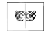
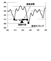
- Japanese Patent Application Laid-Open No. 2008-109966 discloses a technique for displaying an acceleration waveform as a Lissajous figure and displaying the acceleration distribution of the body center of gravity. For example, when the temporal change in acceleration in the front-rear direction or the left-right direction of the measurement subject is expressed, a walking posture in an ideal state with a uniform left-right balance is represented by a broken line diagram as shown in FIG. 23A.
- a walking posture with a large step length of the right foot is represented by a broken line diagram with a large acceleration in the front-rear direction in the cycle when walking with the right foot as shown in FIG. 23B.
- the walking posture with the right center of gravity is represented by a broken line diagram with a large acceleration change on the right side in the period of the right foot walking period as shown in FIG. 24A.
- the walking posture which is called the crotch, has a large step distance
- the left and right walking posture is as shown in FIG. 24B in the cycle of the walking period of one leg (right leg in the figure). It is represented by a broken line diagram with a small change in acceleration before and after.
- the present invention has been made in view of such problems, and an object of the present invention is to provide a walking posture determination device that can easily and in real time determine a walking posture.
- a walking posture determination device includes a main body portion, an acceleration sensor for detecting acceleration of the main body portion, an index value in the index representing the walking posture, and a walking posture.
- An index value in an index representing a walking posture is calculated using a storage unit for storing the correspondence with the level and the acceleration in the first direction detected by the acceleration sensor, and the walking posture level to which the calculated index value belongs
- an output unit for outputting the walking posture level determined by the calculating unit as the walking posture determination result.
- the index representing the walking posture is at least one of a stride, a center of gravity balance, and a step.
- the storage unit corresponds to each of the index values representing the plurality of walking postures and the walking posture level, and the combination of the index value or the walking posture level for the plurality of walking posture indicators and the type of the walking posture.
- the calculation unit determines the type of walking posture according to the calculated index value, and the output unit displays the type of walking posture determined by the calculation unit as the determination result of the walking posture. To do.
- the calculation unit determines the walking posture level for each of the indices representing the plurality of walking postures, and the output unit displays the walking posture level determined by the calculation unit as one graph with each index as an axis. Indicates the walking posture displayed on the screen.
- the output unit displays the walking posture level on a screen with a bubble chart at a position or size corresponding to the determined walking posture level as a result of determining the walking posture.
- the walking posture determination device further includes an input unit for receiving an input of a walking posture level as a target level.
- the calculation unit calculates a difference between the determined walking posture level and the input walking posture level, and the output unit further outputs the difference calculated by the calculation unit.
- the output unit performs at least one of output by a display screen, output by a vibration device, output by light, and output by sound.
- the index representing the walking posture is a stride
- the storage unit stores the level of the balance between the stride of the left foot walking section and the stride of the right foot walking section in association with the index value as the walking posture level for the stride.
- the computing unit uses the acceleration in the first direction to extract the acceleration of the right foot walking section and the acceleration of the left foot walking section out of the acceleration in the second direction of the main body, and the right foot walking section as an index value.
- the difference between the acceleration and the acceleration of the left leg walking section is calculated or a ratio is calculated, and the balance level between the step length of the left leg walking section and the step length of the right leg walking section to which the calculated index value belongs is determined, and an output unit Outputs the balance between the step length of the left foot walking section and the step length of the right foot walking section determined by the calculation unit as the determination result of the walking posture.
- the index representing the walking posture is the center of gravity balance
- the storage unit stores the level of balance between the right center of gravity and the left center of gravity in association with the index value as the walking posture level for the center of gravity balance
- the computing unit And calculating an average value of the acceleration in the first direction for a predetermined period as the index value to determine the level of balance between the right center of gravity and the left center of gravity to which the calculated index value belongs, As the determination result of the walking posture, the level of balance between the right center of gravity and the left center of gravity determined by the calculation unit is output.
- the index representing the walking posture is a step
- the storage unit stores the level of the step width in association with the index value as the walking posture level for the step
- the calculation unit sets the step as the index.
- the calculation of the amplitude of the acceleration change in the direction 1 is performed to determine the level of the step to which the calculated index value belongs, and the output unit is determined by the calculation unit as the determination result of the walking posture Output the level of step width.
- a walking posture can be determined easily and in real time without requiring a large-scale device. Further, by visually displaying the determination result, the determination result can be grasped without having specialized knowledge, and the walking posture can be easily improved and corrected.
- FIG. 5 is a flowchart showing a flow of step determination performed in S ⁇ b> 70 of FIG. 4.
- FIG. It is a figure which shows the specific example of the acceleration data of the left-right axis direction in a certain step level. It is a figure which shows the specific example of the acceleration data of the left-right axis direction in another step distance level. It is a figure which shows the specific example of the table for step determination. It is a figure which shows the specific example of a display of a step determination result.
- the determination device for determining the walking posture is realized by a pedometer.
- the device that realizes the walking posture determination device is not limited to a pedometer, and may be any device as long as it can detect a change in acceleration associated with walking of the person to be measured, which will be described later.
- a system including a detection device for detecting a change in acceleration and a processing device (such as a computer) connected to the device and processing a detection result of the detection device may be used. .
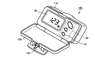
- a pedometer 100 has a small-sized main body casing that can be carried, and the main body casing is divided into a case main body 110, a cover body 120, and a clip body 130. ing.
- the case main body 110 has a display surface on which a display 20 capable of displaying various information such as the counted number of steps and calorie consumption and a button 30 for accepting an operation by the user.
- the button 30 includes a determination button 31 for instructing start of a walking posture determination operation described later.
- the lower end of the case main body 110 and the cover body 120 are rotatably connected around the joint portion, and the pedometer 100 is opened or closed by the rotation of the joint portion.
- a clip body 130 is provided on the surface of the cover body 120 opposite to the surface facing the display surface of the case body 110. The clip body 130 makes it possible to attach the pedometer 100 to the vicinity of the user's second sacrum, the left and right hips, etc. as shown in FIG. 1B.
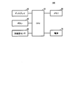
- pedometer 100 is executed by CPU (Central Processing Unit) 10 for controlling the whole, display 20 and button 30, acceleration sensor 40, and CPU 10 as an example of a hardware configuration.
- a memory 50 for storing a program to be executed and a power source 70 such as a battery.
- the acceleration sensor 40 includes two sensors provided at an angle at which acceleration in at least two directions to be described later can be measured out of three orthogonal axes in order to obtain acceleration data used in a determination process to be described later.
- the acceleration sensor 40 is a sensor that detects a change in acceleration in each axial direction in order to detect body movement, and is not limited to an acceleration sensor as long as it is a sensor that similarly detects body movement.
- a gyro or a magnetic sensor for detecting each acceleration may be mounted.
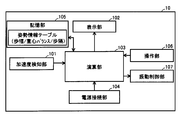
- pedometer 100 includes, as an example of a functional configuration, acceleration detection unit 101 for detecting acceleration based on an input from acceleration sensor 40 and a display unit for controlling display on display 20. 102, a calculation unit 103 for performing acceleration calculation and posture determination calculation described later, a power supply connection unit 104 for performing processing for supplying power to the entire apparatus by connecting to the power source 70, and a calculation unit 103 A storage unit 105 for storing a posture information table, determination results, and the like, which will be described later, and an operation unit 106 for receiving input of an operation signal from the button 30 and inputting a necessary signal to the calculation unit 103.
- These functions may be formed in the CPU 10 by the CPU 10 reading and executing a program stored in the memory 50, or at least a part thereof may be configured by hardware such as an electric circuit. .
- the calculation unit 103 determines that the measurement subject has performed a walking motion using the acceleration detected by the acceleration detection unit 101 and a threshold value stored in advance, and counts the number of steps. Further, the amount of exercise of the measured person is calculated using the height or stride of the measured person previously stored in the storage unit 105 or the like. The amount of exercise corresponds to the amount of movement (movement distance), calorie consumption, and the like. Moreover, the calculating part 103 can also calculate the exercise amount of each direction with respect to a to-be-measured person mentioned later as an exercise amount.
- the calculation unit 103 performs a calculation for determining the walking posture.
- the operation illustrated in FIG. 4 is started when the operation unit 106 receives an operation signal from the determination button 31 when the determination button 31 is pressed.
- the calculation unit 103 may automatically start when body movement is detected and the number of steps is measured.
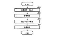
- calculation unit 103 of pedometer 100 receives an input of acceleration data from acceleration detection unit 101 (step (hereinafter abbreviated as S) 10), and uses the acceleration data to indicate a walking posture index.
- step (hereinafter abbreviated as S) 10) uses the acceleration data to indicate a walking posture index.
- the stride determination (S30), the center-of-gravity balance determination (S50), and the step determination (S70) are performed, and the values of the respective indexes are calculated.
- Each determination result may be displayed after each determination, or may be displayed comprehensively after all determinations.
- the walking posture determination operation shown in FIG. 4 is repeated. Then, the operation ends at a timing such as when the operation unit 106 receives an operation signal from the determination button 31 again, that is, at a timing when an operation for ending the determination operation is detected. Alternatively, it may be automatically terminated when body movement is no longer detected by the calculation unit 103.
- step length determination S30
- S50 center-of-gravity balance determination
- step distance determination S70
- the acceleration data input in S10 will be described with reference to FIG.
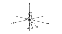
- the acceleration sensor 40 by measuring with the acceleration sensor 40, the acceleration in the x-axis direction as the acceleration in the left-right axis direction and the acceleration in the y-axis direction as the acceleration in the vertical axis direction shown in FIG. , Acceleration in at least two directions is input.
- the calculation unit 103 performs stride determination using acceleration data in the y-axis direction, performs gravity center balance determination using acceleration data in the x-axis direction, and uses acceleration data in the x-axis direction. Perform step distance determination.
- the calculation unit 103 performs calculation for determining the walking posture using acceleration data as an index representing body movement.
- the movement amount calculated from the acceleration, the calorie consumption, etc. may be performed using momentum. In this case, the same calculation as that described later can be performed.
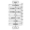
- step length determination in S30 calculation unit 103 determines acceleration in the right foot walking period and acceleration in the left foot walking period from acceleration data in the vertical axis direction (y direction) in S100.
- the walking period with one foot that is, the walking period for one step
- the walking period for one step is a period from the ground contact of the foot to the ground contact of the next foot.
- the right acceleration among the accelerations in the left-right axis direction (x direction) is maximized
- the left acceleration in the left-right axis directions (x direction) is maximized.
- the right acceleration is positive and the left acceleration is negative. Therefore, the upward acceleration change period indicates the right leg walking period, and the downward acceleration.
- the change period represents the left leg walking period.
- the acceleration in the vertical axis direction (y direction)
- the acceleration gradually increases from 0 to reach the maximum value, then gradually decreases and reaches 0 to the minimum value. Thereafter, the change gradually increases and returns to 0.
- the acceleration change represented by the dotted line in FIG. 7 the acceleration increasing side is positive and the deceleration side is negative, so that a pair of periods convex upward and convex downward is the walking period of one foot. (That is, the walking period for one step).
- the calculation unit 103 superimposes the acceleration data cycle in the left-right axis direction in synchronization with the cycle of the acceleration data in the vertical axis direction to synchronize the measurement time, thereby accelerating the acceleration in the vertical axis direction.
- the calculation unit 103 calculates the maximum amplitude YR of the acceleration in the vertical axis direction (y direction) determined in S100 (the difference between the maximum value and the minimum value of the acceleration change period, the same applies hereinafter) and the left foot
- the maximum amplitude YL of acceleration in the vertical axis direction (y direction) during the walking period is calculated (S101, S103).
- the calculation unit 103 calculates a difference YR ⁇ YL between the maximum amplitude YR and the maximum amplitude YL or a ratio YR / YL as the index value (S105).
- the storage unit 105 stores a stride determination table that defines the correspondence between the relationship between the left and right amplitudes during walking and the stride level as shown in FIG. The stride determination table of FIG.
- the stride level becomes larger as the stride of the right foot is larger than the stride of the left foot, and is 0 at the same time, and is represented by a value that becomes smaller as the stride of the left foot is larger than the stride of the right foot.
- the stride determination table of FIG. 9 is used when the calculation unit 103 performs calculation for stride determination using acceleration as an index representing body movement.
- the stride determination table has a difference between the movement amounts of the left and right feet from the reference movement amount, or a reference.
- the reference movement amount at this time includes a value (for example, height ⁇ 100 cm, etc.) calculated from the height of the measurement person stored in advance in the storage unit 105, a stride, a value stored in advance, and the like. Applicable.
- the calculation unit 103 refers to the stride determination table, and in S109, the stride level specified by the difference YR-YL or the ratio YR / YL, which is the index value calculated in S105, is set as the stride level of the person to be measured. judge.
- the stride level is determined to be ⁇ 1 representing normal in S109.
- the stride level is determined to be +5 indicating that the stride of the right foot is large in S109.
- the display unit 102 performs processing for displaying the determination result on the display 20.
- the display unit 102 stores the correspondence between the stride level and the display position in advance, determines the position according to the determination result in S109 as the display position, and other display positions. Have a different display. By displaying as shown in FIG. 10, even a user who has no specialized knowledge can intuitively understand how much the stride of which foot is larger (smaller) than the stride of the other foot. can do.
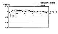
- the calculation unit 103 determines the center of gravity balance, which is an index, as the index value by using a predetermined time of acceleration in the left-right axis direction (x direction) ( For example, an average value X0 to 5 seconds (5 seconds) is calculated (S203).
- the average value X0 to 5 seconds of acceleration in the left and right axis direction (x direction) is almost 0 [G]. Yes, it can be said that the left and right acceleration changes during walking are almost equal.
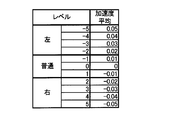
- the average value X0 to 5 seconds of acceleration in the left-right axis direction (x direction) is a negative value indicating that the right acceleration is larger. Therefore, as a posture information table in the storage unit 105, as shown in FIG.
- the center of gravity determination stipulating the correspondence between the average value X0 to 5 seconds of acceleration in the left-right axis direction (x direction) during walking and the center of gravity level.
- a table is stored.
- the center of gravity level is expressed as a value that increases as the center of gravity deviates to the left, 0 when the center of gravity is substantially equal to the left and right, and decreases as the center of gravity deviates to the right.
- the calculation unit 103 refers to the center-of-gravity determination table, and in S207, determines the center-of-gravity level specified by the average value X0 to 5 seconds, which is the index value calculated in S203, as the level of the center of gravity of the measurement subject.
- the center-of-gravity determination table shown in FIG. 13 is based on the assumption that the pedometer 100 is attached to the center of the person to be measured in the left-right axis direction (for example, the umbilical position).
- the level of the center of gravity is defined based on Therefore, when the pedometer 100 is mounted on the left side (for example, the left waist) or the right side (for example, the right waist) of the person to be measured, the storage unit 105 has a left-right bias considering the mounting position bias.
- a left and right center of gravity determination table that prescribes the level of the center of gravity is further stored, and the arithmetic unit 103 uses the center of gravity to be used by pressing a button (not shown) indicating the mounting position included in the button 30.
- a determination table may be selected.
- the operation unit 103 corrects the center-of-gravity determination table shown in FIG. 13 according to the mounting position by an operation such as pressing a button (not shown) that designates the mounting position included in the button 30, and balances the center of gravity. It may be used for determination.
- the display unit 102 performs processing for displaying the determination result on the display 20.
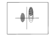
- a process for displaying the size of the foot shape on the side where the center of gravity is biased is performed.
- the display unit 102 stores the correspondence relationship between the barycentric level and the display size in advance, determines the size according to the determination result in S207 as the display size, and selects the corresponding foot pattern. Is displayed in the determined size.
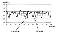
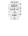
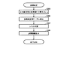
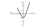
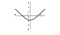
- the calculation unit 103 determines an acceleration change of acceleration in the left-right axis direction (x direction) as the index value when determining the step as an index.
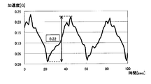
- a difference Xp ⁇ p between the maximum value and the minimum value in one cycle is calculated (S303).
- the difference Xp ⁇ p obtained from the acceleration data in the left-right axis direction (x direction) is 0.08 to 0.12 [G].
- the step is higher than the normal step, for example, the shoulder width, in one cycle of acceleration change corresponding to the walking period consisting of a pair of left foot walking period and right foot walking period Since the change in left and right acceleration is large, that is, because the left and right shake is large, the difference Xp ⁇ p obtained from the acceleration data in the horizontal axis direction (x direction) is larger than 0.14 [G]. Therefore, as the posture information table in the storage unit 105, as shown in FIG.
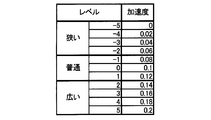
- step 17 the difference between the maximum value and the minimum value of acceleration in one cycle of acceleration change in the left-right axis direction (x direction) during walking.
- a step determination table that defines the correspondence between Xp-p and the step level is stored.
- the step level increases as the step increases, and is expressed as a value that becomes zero as the step is a normal width of the general shoulder width.
- step S305 the calculation unit 103 refers to the step determination table, and in step S307, determines the step level specified by the difference Xp-p, which is the index value calculated in step S303, as the step level of the measurement subject. .
- the step determination table shown in FIG. 17 is also based on the assumption that the pedometer 100 is attached to the center in the left-right axis direction such as the umbilical position of the measurement subject. Similar to the center of gravity determination table, each step determination table for use when worn on the left or right side of the measurement subject may be stored, or may be used after being corrected according to the mounting position. Good.
- the display unit 102 performs processing for displaying the determination result on the display 20.
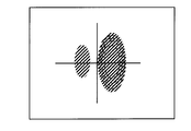
- processing is performed for displaying with a foot shape having an interval corresponding to the size of the step in the bubble chart simulating the foot shape shown in FIG.
- the display unit 102 stores a correspondence relationship between the step level and the display position (foot type interval) in advance, and determines the interval according to the determination result in S307 as the display interval.
- the left and right foot molds are displayed at the intervals.
- the determination result of the walking posture can be obtained without using a large-scale device.
- the determination operation is performed at the time of walking measurement in the pedometer 100, the determination result of the walking posture can be obtained in real time.
- the determination result is displayed in a bubble chart simulating a foot shape, so that even a user who does not have specialized knowledge can intuitively grasp the determination result.
- the walking posture can be easily evaluated. As a result, it is possible to facilitate guidance for improving the walking posture of the person to be measured and correction for bringing the walking posture closer to the ideal walking posture.
- the pedometer 100 displays each determination result after each determination. However, instead of or in addition to such a display, after the step determination in S30, the center-of-gravity balance determination in S50, and the step determination in S70, at least two of these determination results May be displayed centrally.
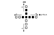
- the display unit 102 reads out the stride level determined in S109 and the barycentric level determined in S207 from the calculation unit 103, as shown in FIG. 19A, with the stride level as the vertical axis and the barycentric level as the horizontal axis. Bar graph display and level display as shown in FIG. 19B can be performed.
- the display unit 102 can display each determination result in a three-dimensional graph.
- the display unit 102 changes the display range based on the determination result. That is, preferably, the display unit 102 determines a display range in which the level determined by the calculation unit 103 is near the maximum value as a determination result, and generates display data.
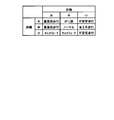
- the storage unit 105 further stores a correspondence relationship between at least two determination results of stride determination, center-of-gravity balance determination, and step determination and the type of walking posture as shown in FIG.
- the unit 103 may determine the type of walking posture based on the determination result after these determinations.
- FIG. 20 shows an example in which the correspondence relationship between the range to which the level belongs as a determination result (large, medium, small) and the type of walking posture is stored.
- the correspondence between the level and the type of walking posture may be stored as the determination result, or the correspondence between the index value and the type of walking posture may be stored as the determination result.
- the walking posture type can be determined and displayed in the same manner as in the following example.
- the result of the stride determination and the result of the step determination are the stride level associated with the large stride and the step level associated with the medium to large stride, respectively.
- the calculation unit 103 determines that the type of walking posture is “high load walking”.
- the stride level is associated with the stride and the stride level is associated with the large step
- the calculation unit 103 determines that the type of walking posture is “grotch”. If the step level is associated with a small step and the step level is associated with a large or small step, the calculation unit 103 determines that the type of walking posture is “unstable walking”. To do.
- the calculation unit 103 sets the type of walking posture as “catwalk (how to walk the model)”. Is determined. In addition, when the stride level is associated with the stride and the step level is associated with the step, the calculation unit 103 determines that the walking posture type is “normal”. When the walking posture is determined, the type of walking posture is displayed on the display 20 by the display unit 102 after each determination. The type of walking posture may be displayed together with the determination result of the walking posture.
- pedometer 100 refers to a stored posture information table and is defined in correspondence with the measurement value in the table.
- the level is assumed to be the judgment result.
- a target level may be set in advance as an ideal walking posture, and a difference from the level may be displayed.
- the operation unit 106 receives an input of a target level by operating the button 30 and inputs the target level to the calculation unit 103.
- options of how to walk as a target are displayed on the display 20, and the operation unit 106 accepts selection by the button 30, so You may set the target level corresponding to the way of walking selected with reference to the stored correspondence.
- the calculation unit 103 calculates the difference between the index value (acceleration in the horizontal axis direction, acceleration in the vertical axis direction, etc.) used for the determination as the difference between the level determined by the determination operation and the input target level. calculate.
- the display unit 102 displays the difference from the target level calculated by the calculation unit 103 as shown in FIG. 21A instead of or in addition to the bubble chart display as shown in FIG. Instead of the display as shown in FIG. 21A, a bubble chart simulating a foot shape may be displayed in the same manner as the determination result (level) described above.
- the user can intuitively recognize the difference between the target walking posture and the actual walking posture, making it easy to improve the walking posture and to correct the walking posture closer to the ideal walking posture. can do.
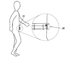
- the pedometer 100 may be connected to the vibration device, and the difference from the target level calculated by the calculation unit 103 may be notified by vibrations in the vibration device.
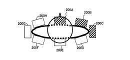
- the pedometer 100 is connected to a plurality of vibration devices 200A to 200H. As shown in FIG. 21B, it is assumed that these vibration devices are respectively mounted at prescribed positions along the circumference of a part where the person to be measured is easily aware of walking, such as around the waist of the measurement subject. Specifically, referring to FIG. 21B, it is assumed that vibration devices 200A to 200H are mounted in the order of vibration devices 200A to 200H at substantially equal intervals clockwise from the center of the measurement subject, for example, from the umbilicus position.
- the functional configuration of the pedometer 100 includes a vibration control unit 107 for controlling the vibrations of the vibration devices 200A to 200H, as shown in FIG.
- the vibration control unit 107 stores in advance a vibration device to be vibrated among the vibration devices 200A to 200H and a correspondence relationship between the difference between the vibration level and the target level.
- the difference from the target level for the stride determination is associated with the degree of vibration of the vibration device 200A attached to the center of the subject and the vibration device 200E attached to the center of the back.
- the vibration device 200A and the striking device 200E are vibrated if the stride of the left foot is larger than the target level, depending on the difference from the target level.
- the degree of vibration can be associated.
- the vibration of the vibration device 200 ⁇ / b> C mounted on the right side and the vibration device 200 ⁇ / b> G mounted on the left side of the measurement subject For example, when the center of gravity is biased to the right of the target level or when the step of the right foot is larger than the target level, the vibration device 200C is vibrated and the center of gravity is higher than the target level. When it is biased to the left or when the step of the left foot is larger than the target level, the vibration device 200G is vibrated, and the degree of vibration according to the difference from the target level can be associated.
- the vibration that is worn between the left and right sides of the measurement subject and the front back center can be associated with each other, and the vibration device at a location corresponding to each determination can be vibrated with the vibration level according to the difference from the target level.
- the measurement subject can feel the determination result without visually recognizing the display 20 during walking, and the walking posture can be an ideal walking. It can be corrected to approach the posture.
- the vibration control unit 107 preferably controls the vibration device to vibrate during a predetermined period within the walking period of one leg. Specifically, as shown in FIG. 22, the vibration control unit 107 performs the next grounding from a substantially intermediate point in the walking period of one foot, which is a period from the grounding of one foot to the next grounding. The vibration device is controlled to vibrate during the period up to.
- the substantially intermediate time point of the walking period of one leg is calculated from acceleration data in the vertical axis direction in the walking period before the walking period to be vibrated at least, and is stored in the vibration control unit 107, so that the vibration timing can be determined. Can be controlled.
- the difference from the target level is notified by the display screen on the display 20 or the vibration of the vibration device.
- the notification is made by an output device such as light or sound, or a combination thereof. May be.
- the determination result may be output in the same manner.
- the computer may be mounted on the pedometer 100 or connected to the pedometer 100 and receives data serving as an index representing body movement such as acceleration data from the pedometer 100 to perform a determination operation. It may be a computer.
- Such a program is stored on a computer-readable recording medium such as a flexible disk attached to the computer, a CD-ROM (Compact Disk-Read Only Memory), a ROM (Read Only Memory), a RAM (Random Access Memory), and a memory card. And can be provided as a program product. Alternatively, the program can be provided by being recorded on a recording medium such as a hard disk built in the computer. A program can also be provided by downloading via a network.
- a computer-readable recording medium such as a flexible disk attached to the computer, a CD-ROM (Compact Disk-Read Only Memory), a ROM (Read Only Memory), a RAM (Random Access Memory), and a memory card.
- the program can be provided by being recorded on a recording medium such as a hard disk built in the computer.
- a program can also be provided by downloading via a network.
- the program according to the present invention is a program module that is provided as a part of a computer operating system (OS) and calls necessary modules in a predetermined arrangement at a predetermined timing to execute processing. Also good. In that case, the program itself does not include the module, and the process is executed in cooperation with the OS. A program that does not include such a module can also be included in the program according to the present invention.
- OS computer operating system
- the program according to the present invention may be provided by being incorporated in a part of another program. Even in this case, the program itself does not include the module included in the other program, and the process is executed in cooperation with the other program. Such a program incorporated in another program can also be included in the program according to the present invention.
- the provided program product is installed in a program storage unit such as a hard disk and executed.
- the program product includes the program itself and a recording medium on which the program is recorded.
- vibration control unit 10 CPU, 20 display, 30 button, 31 determination button, 40 acceleration sensor, 50 memory, 70 power supply, 100 pedometer, 101 acceleration detection unit, 102 display unit, 103 calculation unit, 104 power connection unit, 105 storage unit, 106 Operation unit, 107 vibration control unit, 110 case body, 120 cover body, 130 clip body, 200, 200A to 200H vibration device.
Landscapes
- Health & Medical Sciences (AREA)
- Life Sciences & Earth Sciences (AREA)
- Engineering & Computer Science (AREA)
- Physics & Mathematics (AREA)
- Pathology (AREA)
- Medical Informatics (AREA)
- Dentistry (AREA)
- Oral & Maxillofacial Surgery (AREA)
- Veterinary Medicine (AREA)
- Biophysics (AREA)
- Public Health (AREA)
- Biomedical Technology (AREA)
- Heart & Thoracic Surgery (AREA)
- General Health & Medical Sciences (AREA)
- Molecular Biology (AREA)
- Surgery (AREA)
- Animal Behavior & Ethology (AREA)
- Remote Sensing (AREA)
- General Physics & Mathematics (AREA)
- Radar, Positioning & Navigation (AREA)
- Physiology (AREA)
- Measurement Of The Respiration, Hearing Ability, Form, And Blood Characteristics Of Living Organisms (AREA)
Priority Applications (3)
| Application Number | Priority Date | Filing Date | Title |
|---|---|---|---|
| CN201080034707.4A CN102469959B (zh) | 2009-10-06 | 2010-10-04 | 行走姿势判定装置 |
| DE112010003983T DE112010003983T5 (de) | 2009-10-06 | 2010-10-04 | Gehhaltungsbestimmungsvorrichtung |
| US13/338,821 US9149212B2 (en) | 2009-10-06 | 2011-12-28 | Walking posture determination apparatus |
Applications Claiming Priority (2)
| Application Number | Priority Date | Filing Date | Title |
|---|---|---|---|
| JP2009232673A JP5504810B2 (ja) | 2009-10-06 | 2009-10-06 | 歩行姿勢判定装置、制御プログラム、および制御方法 |
| JP2009-232673 | 2009-10-06 |
Related Child Applications (1)
| Application Number | Title | Priority Date | Filing Date |
|---|---|---|---|
| US13/338,821 Continuation US9149212B2 (en) | 2009-10-06 | 2011-12-28 | Walking posture determination apparatus |
Publications (1)
| Publication Number | Publication Date |
|---|---|
| WO2011043294A1 true WO2011043294A1 (ja) | 2011-04-14 |
Family
ID=43856749
Family Applications (1)
| Application Number | Title | Priority Date | Filing Date |
|---|---|---|---|
| PCT/JP2010/067365 Ceased WO2011043294A1 (ja) | 2009-10-06 | 2010-10-04 | 歩行姿勢判定装置 |
Country Status (5)
| Country | Link |
|---|---|
| US (1) | US9149212B2 (enExample) |
| JP (1) | JP5504810B2 (enExample) |
| CN (1) | CN102469959B (enExample) |
| DE (1) | DE112010003983T5 (enExample) |
| WO (1) | WO2011043294A1 (enExample) |
Families Citing this family (35)
| Publication number | Priority date | Publication date | Assignee | Title |
|---|---|---|---|---|
| JP5633472B2 (ja) * | 2011-05-25 | 2014-12-03 | 富士通株式会社 | 電子機器、及び傾きバランス算出プログラム |
| JP5811360B2 (ja) * | 2012-12-27 | 2015-11-11 | カシオ計算機株式会社 | 運動情報表示システムおよび運動情報表示方法、運動情報表示プログラム |
| JP2014217692A (ja) * | 2013-05-10 | 2014-11-20 | オムロンヘルスケア株式会社 | 歩行姿勢計およびプログラム |
| JP6111837B2 (ja) | 2013-05-10 | 2017-04-12 | オムロンヘルスケア株式会社 | 歩行姿勢計およびプログラム |
| JP2014217693A (ja) * | 2013-05-10 | 2014-11-20 | オムロンヘルスケア株式会社 | 歩行姿勢計およびプログラム |
| JP6075198B2 (ja) * | 2013-05-10 | 2017-02-08 | オムロンヘルスケア株式会社 | 歩行姿勢計およびプログラム |
| JP5888309B2 (ja) * | 2013-10-31 | 2016-03-22 | カシオ計算機株式会社 | トレーニング支援装置およびシステム、フォーム解析装置および方法、ならびにプログラム |
| US10285628B2 (en) | 2014-02-28 | 2019-05-14 | Microstone Corporation | Method for detecting ambulatory status and device for detecting ambulatory status |
| JP6134680B2 (ja) * | 2014-03-19 | 2017-05-24 | 日本電信電話株式会社 | 歩行支援装置、歩容計測装置、方法及びプログラム |
| US10001386B2 (en) | 2014-04-03 | 2018-06-19 | Apple Inc. | Automatic track selection for calibration of pedometer devices |
| CN104207783B (zh) * | 2014-09-02 | 2016-06-01 | 北京智谷技术服务有限公司 | 左右侧确定方法、装置及便携设备 |
| CN104224184B (zh) * | 2014-09-02 | 2016-08-17 | 北京智谷技术服务有限公司 | 左右侧确定方法、装置及便携设备 |
| US10448867B2 (en) * | 2014-09-05 | 2019-10-22 | Vision Service Plan | Wearable gait monitoring apparatus, systems, and related methods |
| US11918375B2 (en) | 2014-09-05 | 2024-03-05 | Beijing Zitiao Network Technology Co., Ltd. | Wearable environmental pollution monitor computer apparatus, systems, and related methods |
| JP6369811B2 (ja) * | 2014-11-27 | 2018-08-08 | パナソニックIpマネジメント株式会社 | 歩行解析システムおよび歩行解析プログラム |
| US10959649B2 (en) * | 2015-01-29 | 2021-03-30 | Beijing Shunyuan Kaihua Technology Limited | Systems and methods for stride length calibration |
| CN105147295A (zh) * | 2015-02-15 | 2015-12-16 | 南京蓝莓网络科技有限公司 | 一种基于加速度传感器的跑步姿势判断和矫正方法 |
| KR101702462B1 (ko) * | 2015-06-16 | 2017-02-03 | 전진홍 | 신체 상태 측정장치 및 측정방법 |
| CN104887372B (zh) * | 2015-06-25 | 2018-01-02 | 京东方科技集团股份有限公司 | 一种行走、站立姿势矫正装置、鞋子、鞋垫及矫正方法 |
| JP6660110B2 (ja) * | 2015-07-23 | 2020-03-04 | 原田電子工業株式会社 | 歩行解析方法および歩行解析システム |
| JP6578874B2 (ja) * | 2015-10-15 | 2019-09-25 | 花王株式会社 | 歩行周期の検出方法及び検出装置 |
| JP6697300B2 (ja) * | 2016-03-25 | 2020-05-20 | 株式会社ジンズホールディングス | 情報処理方法、プログラム及び情報処理装置 |
| JP2018014031A (ja) * | 2016-07-22 | 2018-01-25 | 株式会社Soken | 車載報知システム及びコンピュータプログラム |
| CN106217353A (zh) * | 2016-08-17 | 2016-12-14 | 尖叫智能科技(上海)有限公司 | 基于多轴加速度传感器的外骨骼机器人步态控制方法 |
| CN108089729A (zh) * | 2016-11-23 | 2018-05-29 | 中兴通讯股份有限公司 | 终端及其实现阅读姿势检测的方法 |
| JP6508174B2 (ja) * | 2016-11-29 | 2019-05-08 | カシオ計算機株式会社 | ランニング解析装置、ランニング解析方法及びランニング解析プログラム |
| JP6737505B2 (ja) * | 2017-03-03 | 2020-08-12 | 株式会社ノーニューフォークスタジオ | 歩行教示システム、歩行教示方法 |
| JP6853532B2 (ja) * | 2017-03-13 | 2021-03-31 | 国立大学法人横浜国立大学 | 指標値算出装置、指標値算出方法及びプログラム |
| FI3626169T3 (fi) * | 2017-05-15 | 2023-04-21 | Fujitsu Ltd | Tiedonkäsittelylaite, tiedonkäsittelyjärjestelmä ja tiedonkäsittelymenetelmä |
| CN107631736B (zh) * | 2017-09-13 | 2020-12-11 | 广东高驰运动科技有限公司 | 一种步幅估算方法和装置 |
| JP6307673B1 (ja) * | 2017-10-04 | 2018-04-04 | まさみ 仁頃 | 二肢の間隔計測器を用いた歩行および走行行動提示システム |
| JP7006128B2 (ja) * | 2017-10-24 | 2022-01-24 | 株式会社アイシン | 情報処理装置 |
| US10722128B2 (en) | 2018-08-01 | 2020-07-28 | Vision Service Plan | Heart rate detection system and method |
| US11059492B2 (en) | 2018-11-05 | 2021-07-13 | International Business Machines Corporation | Managing vehicle-access according to driver behavior |
| CN113359120B (zh) * | 2020-03-06 | 2024-04-26 | 华为技术有限公司 | 用户活动距离的测量方法、设备和电子设备 |
Citations (7)
| Publication number | Priority date | Publication date | Assignee | Title |
|---|---|---|---|---|
| JP2001218754A (ja) * | 2000-02-14 | 2001-08-14 | Nippon Telegr & Teleph Corp <Ntt> | ウォーキング判定装置 |
| JP2002336376A (ja) * | 2001-05-15 | 2002-11-26 | Mitsubishi Electric Corp | 健康増進システム |
| JP2005352686A (ja) * | 2004-06-09 | 2005-12-22 | Matsushita Electric Ind Co Ltd | リハビリテーション管理装置 |
| JP2008229266A (ja) * | 2007-03-23 | 2008-10-02 | Aisin Seiki Co Ltd | 歩行能力からの運動機能向上メニュー提案システム及び歩行能力からの運動機能向上メニュー提案方法 |
| JP2009000391A (ja) * | 2007-06-23 | 2009-01-08 | Tanita Corp | 歩行評価システム、歩行計、歩行評価プログラムおよび記録媒体 |
| JP2009106377A (ja) * | 2007-10-26 | 2009-05-21 | Panasonic Electric Works Co Ltd | 歩容情報表示システム |
| JP2009106387A (ja) * | 2007-10-26 | 2009-05-21 | Panasonic Electric Works Co Ltd | 歩容改善支援システム |
Family Cites Families (8)
| Publication number | Priority date | Publication date | Assignee | Title |
|---|---|---|---|---|
| US6301964B1 (en) * | 1997-10-14 | 2001-10-16 | Dyhastream Innovations Inc. | Motion analysis system |
| EP1366712A4 (en) * | 2001-03-06 | 2006-05-31 | Microstone Co Ltd | DETECTOR APPLICABLE TO THE MOVEMENT OF A BODY |
| JP2003204953A (ja) * | 2002-01-16 | 2003-07-22 | Nippon Telegr & Teleph Corp <Ntt> | 歩容パターン分類表示装置 |
| JP4178186B2 (ja) * | 2003-08-21 | 2008-11-12 | 国立大学法人 筑波大学 | 装着式動作補助装置、装着式動作補助装置の制御方法および制御用プログラム |
| US7805275B2 (en) * | 2005-03-28 | 2010-09-28 | Asahi Kasei Emd Corporation | Traveling direction measuring apparatus and traveling direction measuring method |
| JP4185108B2 (ja) * | 2006-04-06 | 2008-11-26 | 本田技研工業株式会社 | 運動管理システム |
| JP2008109966A (ja) | 2006-10-30 | 2008-05-15 | Bycen Inc | 動物動作を定量化する方法、動物動作定量化装置 |
| JP2009106374A (ja) * | 2007-10-26 | 2009-05-21 | Panasonic Electric Works Co Ltd | 歩容情報表示システム |
-
2009
- 2009-10-06 JP JP2009232673A patent/JP5504810B2/ja active Active
-
2010
- 2010-10-04 WO PCT/JP2010/067365 patent/WO2011043294A1/ja not_active Ceased
- 2010-10-04 DE DE112010003983T patent/DE112010003983T5/de active Pending
- 2010-10-04 CN CN201080034707.4A patent/CN102469959B/zh active Active
-
2011
- 2011-12-28 US US13/338,821 patent/US9149212B2/en active Active
Patent Citations (7)
| Publication number | Priority date | Publication date | Assignee | Title |
|---|---|---|---|---|
| JP2001218754A (ja) * | 2000-02-14 | 2001-08-14 | Nippon Telegr & Teleph Corp <Ntt> | ウォーキング判定装置 |
| JP2002336376A (ja) * | 2001-05-15 | 2002-11-26 | Mitsubishi Electric Corp | 健康増進システム |
| JP2005352686A (ja) * | 2004-06-09 | 2005-12-22 | Matsushita Electric Ind Co Ltd | リハビリテーション管理装置 |
| JP2008229266A (ja) * | 2007-03-23 | 2008-10-02 | Aisin Seiki Co Ltd | 歩行能力からの運動機能向上メニュー提案システム及び歩行能力からの運動機能向上メニュー提案方法 |
| JP2009000391A (ja) * | 2007-06-23 | 2009-01-08 | Tanita Corp | 歩行評価システム、歩行計、歩行評価プログラムおよび記録媒体 |
| JP2009106377A (ja) * | 2007-10-26 | 2009-05-21 | Panasonic Electric Works Co Ltd | 歩容情報表示システム |
| JP2009106387A (ja) * | 2007-10-26 | 2009-05-21 | Panasonic Electric Works Co Ltd | 歩容改善支援システム |
Also Published As
| Publication number | Publication date |
|---|---|
| US9149212B2 (en) | 2015-10-06 |
| JP2011078534A (ja) | 2011-04-21 |
| CN102469959B (zh) | 2015-05-06 |
| JP5504810B2 (ja) | 2014-05-28 |
| DE112010003983T5 (de) | 2013-01-03 |
| US20120101771A1 (en) | 2012-04-26 |
| CN102469959A (zh) | 2012-05-23 |
Similar Documents
| Publication | Publication Date | Title |
|---|---|---|
| JP5504810B2 (ja) | 歩行姿勢判定装置、制御プログラム、および制御方法 | |
| CN103025241B (zh) | 步行变化判断装置 | |
| US10684304B2 (en) | Foot exercise motion analysis device during moving exercise | |
| US10667726B2 (en) | Gait posture meter and program | |
| CN104436596B (zh) | 运动支持装置及运动支持方法 | |
| JP5896240B2 (ja) | 運動支援装置、運動支援方法及び運動支援プログラム | |
| JP5742423B2 (ja) | 下肢筋力の余裕度を求めるための方法、及びこれに用いる下肢筋力評価装置 | |
| CN102883654A (zh) | 体动检测装置以及体动检测装置的显示控制方法 | |
| JP2010119500A (ja) | 体動バランス検出装置、体動バランス検出プログラム、体動バランス検出方法、および体動バランス診断方法 | |
| JP2012024275A (ja) | 歩行姿勢判定装置 | |
| WO2014181606A1 (ja) | 歩行姿勢計およびプログラム | |
| US20140142466A1 (en) | Physical motion detecting device and control method for physical motion detecting device | |
| CN105435438B (zh) | 运动解析装置以及运动解析方法 | |
| JP6241488B2 (ja) | 運動支援装置、運動支援方法及び運動支援プログラム | |
| JP2009106374A (ja) | 歩容情報表示システム | |
| JP2014217695A (ja) | 歩行姿勢計およびプログラム | |
| JP2005172625A (ja) | 行動検知装置 | |
| JP6432665B2 (ja) | 運動装置、腕降り角度検出方法及びプログラム | |
| JP2006293861A (ja) | 歩数計 | |
| JP2013017614A (ja) | 疲労判定装置 | |
| JP2017070723A (ja) | 情報処理方法、情報処理装置及びプログラム | |
| JP2012045187A (ja) | 携帯型運動量計 | |
| JP6067148B1 (ja) | 情報処理方法、情報処理装置及びプログラム | |
| KR20100023388A (ko) | 복합 센서를 이용한 생활 패턴 측정 장치 및 방법 | |
| JP2008246164A (ja) | 活動量計 |
Legal Events
| Date | Code | Title | Description |
|---|---|---|---|
| WWE | Wipo information: entry into national phase |
Ref document number: 201080034707.4 Country of ref document: CN |
|
| 121 | Ep: the epo has been informed by wipo that ep was designated in this application |
Ref document number: 10821964 Country of ref document: EP Kind code of ref document: A1 |
|
| WWE | Wipo information: entry into national phase |
Ref document number: 112010003983 Country of ref document: DE Ref document number: 1120100039836 Country of ref document: DE |
|
| 122 | Ep: pct application non-entry in european phase |
Ref document number: 10821964 Country of ref document: EP Kind code of ref document: A1 |