WO2011027482A1 - 回転検出装置 - Google Patents
回転検出装置 Download PDFInfo
- Publication number
- WO2011027482A1 WO2011027482A1 PCT/JP2010/001212 JP2010001212W WO2011027482A1 WO 2011027482 A1 WO2011027482 A1 WO 2011027482A1 JP 2010001212 W JP2010001212 W JP 2010001212W WO 2011027482 A1 WO2011027482 A1 WO 2011027482A1
- Authority
- WO
- WIPO (PCT)
- Prior art keywords
- cored bar
- rotation detection
- insertion hole
- external conductor
- fixed
- Prior art date
- Legal status (The legal status is an assumption and is not a legal conclusion. Google has not performed a legal analysis and makes no representation as to the accuracy of the status listed.)
- Ceased
Links
Images






Classifications
-
- G—PHYSICS
- G01—MEASURING; TESTING
- G01P—MEASURING LINEAR OR ANGULAR SPEED, ACCELERATION, DECELERATION, OR SHOCK; INDICATING PRESENCE, ABSENCE, OR DIRECTION, OF MOVEMENT
- G01P3/00—Measuring linear or angular speed; Measuring differences of linear or angular speeds
- G01P3/42—Devices characterised by the use of electric or magnetic means
- G01P3/44—Devices characterised by the use of electric or magnetic means for measuring angular speed
- G01P3/443—Devices characterised by the use of electric or magnetic means for measuring angular speed mounted in bearings
-
- F—MECHANICAL ENGINEERING; LIGHTING; HEATING; WEAPONS; BLASTING
- F16—ENGINEERING ELEMENTS AND UNITS; GENERAL MEASURES FOR PRODUCING AND MAINTAINING EFFECTIVE FUNCTIONING OF MACHINES OR INSTALLATIONS; THERMAL INSULATION IN GENERAL
- F16C—SHAFTS; FLEXIBLE SHAFTS; ELEMENTS OR CRANKSHAFT MECHANISMS; ROTARY BODIES OTHER THAN GEARING ELEMENTS; BEARINGS
- F16C33/00—Parts of bearings; Special methods for making bearings or parts thereof
- F16C33/72—Sealings
- F16C33/723—Shaft end sealing means, e.g. cup-shaped caps or covers
-
- F—MECHANICAL ENGINEERING; LIGHTING; HEATING; WEAPONS; BLASTING
- F16—ENGINEERING ELEMENTS AND UNITS; GENERAL MEASURES FOR PRODUCING AND MAINTAINING EFFECTIVE FUNCTIONING OF MACHINES OR INSTALLATIONS; THERMAL INSULATION IN GENERAL
- F16C—SHAFTS; FLEXIBLE SHAFTS; ELEMENTS OR CRANKSHAFT MECHANISMS; ROTARY BODIES OTHER THAN GEARING ELEMENTS; BEARINGS
- F16C41/00—Other accessories, e.g. devices integrated in the bearing not relating to the bearing function as such
- F16C41/007—Encoders, e.g. parts with a plurality of alternating magnetic poles
-
- G—PHYSICS
- G01—MEASURING; TESTING
- G01D—MEASURING NOT SPECIALLY ADAPTED FOR A SPECIFIC VARIABLE; ARRANGEMENTS FOR MEASURING TWO OR MORE VARIABLES NOT COVERED IN A SINGLE OTHER SUBCLASS; TARIFF METERING APPARATUS; MEASURING OR TESTING NOT OTHERWISE PROVIDED FOR
- G01D5/00—Mechanical means for transferring the output of a sensing member; Means for converting the output of a sensing member to another variable where the form or nature of the sensing member does not constrain the means for converting; Transducers not specially adapted for a specific variable
- G01D5/02—Mechanical means for transferring the output of a sensing member; Means for converting the output of a sensing member to another variable where the form or nature of the sensing member does not constrain the means for converting; Transducers not specially adapted for a specific variable using mechanical means
- G01D5/06—Mechanical means for transferring the output of a sensing member; Means for converting the output of a sensing member to another variable where the form or nature of the sensing member does not constrain the means for converting; Transducers not specially adapted for a specific variable using mechanical means acting through a wall or enclosure, e.g. by bellows, by magnetic coupling
-
- G—PHYSICS
- G01—MEASURING; TESTING
- G01P—MEASURING LINEAR OR ANGULAR SPEED, ACCELERATION, DECELERATION, OR SHOCK; INDICATING PRESENCE, ABSENCE, OR DIRECTION, OF MOVEMENT
- G01P1/00—Details of instruments
- G01P1/02—Housings
- G01P1/026—Housings for speed measuring devices, e.g. pulse generator
-
- G—PHYSICS
- G01—MEASURING; TESTING
- G01P—MEASURING LINEAR OR ANGULAR SPEED, ACCELERATION, DECELERATION, OR SHOCK; INDICATING PRESENCE, ABSENCE, OR DIRECTION, OF MOVEMENT
- G01P3/00—Measuring linear or angular speed; Measuring differences of linear or angular speeds
- G01P3/42—Devices characterised by the use of electric or magnetic means
- G01P3/44—Devices characterised by the use of electric or magnetic means for measuring angular speed
- G01P3/48—Devices characterised by the use of electric or magnetic means for measuring angular speed by measuring frequency of generated current or voltage
- G01P3/481—Devices characterised by the use of electric or magnetic means for measuring angular speed by measuring frequency of generated current or voltage of pulse signals
- G01P3/487—Devices characterised by the use of electric or magnetic means for measuring angular speed by measuring frequency of generated current or voltage of pulse signals delivered by rotating magnets
-
- F—MECHANICAL ENGINEERING; LIGHTING; HEATING; WEAPONS; BLASTING
- F16—ENGINEERING ELEMENTS AND UNITS; GENERAL MEASURES FOR PRODUCING AND MAINTAINING EFFECTIVE FUNCTIONING OF MACHINES OR INSTALLATIONS; THERMAL INSULATION IN GENERAL
- F16C—SHAFTS; FLEXIBLE SHAFTS; ELEMENTS OR CRANKSHAFT MECHANISMS; ROTARY BODIES OTHER THAN GEARING ELEMENTS; BEARINGS
- F16C19/00—Bearings with rolling contact, for exclusively rotary movement
- F16C19/02—Bearings with rolling contact, for exclusively rotary movement with bearing balls essentially of the same size in one or more circular rows
- F16C19/14—Bearings with rolling contact, for exclusively rotary movement with bearing balls essentially of the same size in one or more circular rows for both radial and axial load
- F16C19/18—Bearings with rolling contact, for exclusively rotary movement with bearing balls essentially of the same size in one or more circular rows for both radial and axial load with two or more rows of balls
- F16C19/181—Bearings with rolling contact, for exclusively rotary movement with bearing balls essentially of the same size in one or more circular rows for both radial and axial load with two or more rows of balls with angular contact
- F16C19/183—Bearings with rolling contact, for exclusively rotary movement with bearing balls essentially of the same size in one or more circular rows for both radial and axial load with two or more rows of balls with angular contact with two rows at opposite angles
- F16C19/184—Bearings with rolling contact, for exclusively rotary movement with bearing balls essentially of the same size in one or more circular rows for both radial and axial load with two or more rows of balls with angular contact with two rows at opposite angles in O-arrangement
- F16C19/186—Bearings with rolling contact, for exclusively rotary movement with bearing balls essentially of the same size in one or more circular rows for both radial and axial load with two or more rows of balls with angular contact with two rows at opposite angles in O-arrangement with three raceways provided integrally on parts other than race rings, e.g. third generation hubs
-
- F—MECHANICAL ENGINEERING; LIGHTING; HEATING; WEAPONS; BLASTING
- F16—ENGINEERING ELEMENTS AND UNITS; GENERAL MEASURES FOR PRODUCING AND MAINTAINING EFFECTIVE FUNCTIONING OF MACHINES OR INSTALLATIONS; THERMAL INSULATION IN GENERAL
- F16C—SHAFTS; FLEXIBLE SHAFTS; ELEMENTS OR CRANKSHAFT MECHANISMS; ROTARY BODIES OTHER THAN GEARING ELEMENTS; BEARINGS
- F16C2326/00—Articles relating to transporting
- F16C2326/01—Parts of vehicles in general
- F16C2326/02—Wheel hubs or castors
Definitions
- the present invention relates to a rotation detection device provided in a bearing portion of a wheel of an automobile or the like.
- a rotation detection device is mounted on a bearing portion of an automobile wheel, and a wheel rotation speed used for control of an antilock brake system (ABS) or the like is detected by this rotation detection device.
- ABS antilock brake system
- the rotation detection sensor includes a detection unit and a holder unit made of a hard synthetic resin material that holds the detection unit.
- the connector fitting portion is integrally formed with the holder portion.
- the lead wire which protrudes in a connector fitting part, and an external conductor are connected by the connector attached to the terminal of an external conducting wire being fitted with respect to this connector fitting part.
- the present invention has been made in the background of the above-mentioned circumstances, and a solution to the problem is a novel structure that can achieve both improvement in waterproofness of the rotation detection sensor and downsizing of the entire apparatus.
- An object of the present invention is to provide a rotation detection device.
- a rotation detection sensor is attached to a cored bar fixed to an outer member constituting a wheel bearing device by rotatably supporting an inner member attached to a wheel.
- the rotation detecting device is configured so that the detection unit is opposed to a magnetized rotor provided on the inner member, and a magnetic field variation due to rotation of the magnetized rotor is detected by the detection unit.
- the rotation detection sensor is accommodated and supported in the inner space and supported by the cored bar, and a lead wire extending from the detection part of the rotation detection sensor is electrically connected to an external conductor, and the core
- the external conductor is led out from the internal space through an insertion hole formed in the gold, and a sealing member is fixed on the outer peripheral surface of the external conductor, and is formed in the core metal. Said sealing member is fitted and attached to the insertion hole, and wherein.
- the through hole of the metal core is blocked by the sealing member provided around the external conducting wire. Therefore, it is possible to solve the problem of the gap that occurs in the connector connection. Therefore, it is possible to ensure the waterproofness of the lead portion of the external conductor with sufficient reliability.
- the internal space composed of the cored bar and the outer member can be skillfully used to accommodate the connecting portion of the lead wire and the external conductor and the external conductor, and only the external conductor can be drawn from the cored bar and wired. It becomes possible. Therefore, the size of the entire apparatus can be reduced as compared with the conventional structure in which a large connector fitting portion needs to protrude from the core metal.
- a seal rubber for sealing between the insertion hole of the cored bar and the fitting portion of the sealing member is disposed. It is what I did.
- the cored bar is also used under a usage condition exposed to severe temperature changes. It becomes possible to ensure further waterproofness by flexibly following the strain due to the difference in thermal expansion coefficient between the insertion hole and the sealing member.
- a third aspect of the present invention is the one described in the first or second aspect, wherein the sealing member is integrally formed with a locking projection larger than the insertion hole of the cored bar, The locking protrusion is locked from the inner space side with respect to the cored bar.
- the third aspect even when a force for pulling outward is applied to the external conductor, it is possible to prevent the external conductor from being pulled out by catching the locking protrusion around the insertion hole. Further, it is possible to avoid a pulling force being applied to the connection portion between the lead wire and the external conductor or the rotation detection sensor through the external conductor.
- the cored bar has a cup shape, and an opening portion thereof is fixed to the outer member to cover the cover.
- the inner space is formed inside the cored bar, and an inner case member is fixedly attached to the cored bar, and the detection unit and the outer part are installed inside the inner case member.
- the conductor is assembled.
- the inner case member is further provided in the inner space of the core bar, so that a double case structure is formed, and the detection unit and the external conductor are assembled inside the inner case member. By doing so, their protection is more advanced.
- a press fitting is fitted into the cored bar from the outside of the inner case member and is press-fitted and fixed to the cored bar.
- the inner case member is fixed to the cored bar by a presser fitting.
- FIG. 2 is an end view of the rotation detection device shown in FIG. 1.
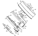
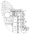
- the disassembled perspective view of the rotation detection apparatus shown in FIG. The principal part enlarged view of FIG.
- the perspective view of the bottom member which comprises the rotation detection apparatus shown in FIG.
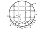
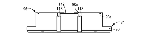
- the top view of the bottom member shown in FIG. The side view of the bottom member shown in FIG.
- the perspective view of the cover member which comprises the rotation detection apparatus shown in FIG.
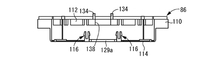
- the top view of the cover member shown in FIG. The side view of the cover member shown in FIG.
- the top view of the sealing member which comprises the rotation detection apparatus shown in FIG.
- FIG. 1 to 3 show a wheel speed sensor 10 according to an embodiment of the present invention relating to a rotation detection device.
- the wheel speed sensor 10 is attached to one end of the wheel bearing device 14 attached to the hub shaft 12 in the axial direction.
- one side of the wheel bearing device 14 in the axial direction (the right side in FIG. 1) is the inside of the vehicle, and the other side in the axial direction (the left side in FIG. 1) is the outside of the vehicle.
- the hub shaft 12 has a shape in which a flange portion 18 that protrudes outward in the direction perpendicular to the axis is provided at an axially intermediate portion of the shaft portion 16. It is fixed to the vehicle outer end portion of the shaft portion 16.
- An annular step surface 20 that extends in a direction perpendicular to the axis is formed on the inner side of the shaft portion 16 than the flange portion 18, and a small-diameter portion 22 having a smaller inner diameter than the outer side of the vehicle than the step surface 20.
- the wheel bearing device 14 attached to the hub shaft 12 includes an inner member 24, an outer member 26, and double-row rolling elements 28.
- the inner member 24 has an annular block shape with a thick and small diameter as a whole, and is externally fixed to the small diameter portion 22 of the hub shaft 12.
- the outer member 26 has a cylindrical shape with a large thickness and a large diameter as a whole.
- the outer member 26 is externally inserted into the shaft portion 16 of the hub shaft 12 to which the inner member 24 is fixed, and the shaft portion 16 and the inner member 24 have respective shafts. It is located outward in the right-angle direction.
- the outer member 26 is mounted on a mounting flange 36 that protrudes outward in a direction perpendicular to the axis in a state where the outer member 26 is fitted in a mounting hole 34 formed in a vehicle body-side support member 32 formed of a knuckle or the like.
- the bolt is fixed to the support member 32 on the vehicle body side.
- the outer member 26 is fixed to the vehicle body side support member 32 in a state in which the rotation is prevented.
- the double row rolling elements 28 include outer ring raceways 38, 38 formed on the inner peripheral surface of the outer member 26, and inner ring raceways 40 formed on the outer peripheral surfaces of the shaft portion 16 of the hub shaft 12 and the inner member 24, respectively. Between 40, it arrange
- a support fitting 42 is fitted to the vehicle inner end of the inner member 24 at the opening portion on the vehicle inner side of the gap formed between the opposite surfaces of the outer member 26 and the inner member 24 in the direction perpendicular to the axis. It is arranged.
- the support fitting 42 protrudes over the entire circumference outward in the direction perpendicular to the axis with respect to the vehicle inner end portion of the cylindrical portion 54 fitted to the inner member 24.
- the outer flange 56 is provided.
- a magnetized rotor 58 is fixed to the inner side of the outer flange 56 on the vehicle.
- the magnetized rotor 58 is formed of a rubber magnet, a plastic magnet, or the like in which N poles and S poles are alternately magnetized in the circumferential direction, and has an annular plate shape as a whole.
- the wheel speed sensor 10 attached to the vehicle inner end of the wheel bearing device 14 includes a cored bar 66.
- the cored bar 66 has a structure in which an opening on one end side in the axial direction of the cylindrical wall 68 is covered with a bottom wall 70 and has a cup shape as a whole.
- An insertion hole 72 that opens in a circular cross section is formed in the center of the bottom wall 70 of the cored bar 66, and a cylindrical portion 74 that protrudes outward in the axial direction is provided at the periphery of the opening. As a result, the insertion hole 72 extends straight in the axial direction in the cylindrical portion 74 with a substantially constant circular cross section.
- the opening portion of the cored bar 66 is fitted and fixed to the vehicle inner end portion of the outer member 26.
- a contact flange 76 that protrudes outward in the direction perpendicular to the axis at the opening edge of the cored bar 66 is formed so as to spread in the direction perpendicular to the axis on the outer peripheral surface of the vehicle inner end of the outer member 26. It is superimposed on the annular contact surface 78.
- the fitting amount (fitting depth) of the metal core 66 with respect to the outer member 26 is defined, and a predetermined gap is formed between the magnetized rotor 58 and a holding projection 120 described later.
- the opening portion of the cored bar 66 is covered and fixed to the vehicle inner end portion of the outer member 26 so that the opening part of the cored bar 66 is covered with the wheel bearing device 14. As a result, an internal space 80 is formed inside the cored bar 66.
- the inner case member 82 is disposed in the inner space 80.
- the inner case member 82 includes a bottom member 84 and a lid member 86.
- the bottom member 84 has a shallow dish shape in which a peripheral wall 90 projects from the outer peripheral edge of the disc-shaped bottom wall 88 over the entire circumference.
- a reinforcing rib 92 is projected on the bottom wall 88 in a lattice shape.
- a central hole 94 is formed in the central portion of the bottom wall 88.
- the central hole 94 is opened with a larger cross-sectional shape than the insertion hole 72 of the cored bar 66. Note that, as shown in FIG. 6, in the top view of the central hole 94, a cut-off portion 95 is provided in one of the square portions (lower left portion).
- a curved projection 96 that extends in an appropriate length in the circumferential direction and projects in the same direction as the circumferential wall 90 is provided on the outer peripheral portion of the bottom wall 88.
- the curved protrusion 96 has a structure in which a pair of curved walls 98a and 98b opposed to each other at a predetermined distance in the direction perpendicular to the axis are connected by a plurality of connecting walls 100 provided at appropriate intervals in the circumferential direction.
- the protruding height is larger than that of the peripheral wall 90 and the reinforcing rib 92.
- the outer curved walls 98 a and 98 b are provided integrally with the peripheral wall 90.
- a stepped surface 102 extending in the height direction while being curved in the circumferential direction is formed at the protruding end portion of the outer curved wall 98a, and the radially inner side from the outer side is sandwiched by the stepped surface 102. Is also low. As a result, a support surface 106 is formed at the protruding end of the outer curved wall 98a at the same height as the protruding end surface of the connecting wall 100 on the radially inner side of the stepped surface 102.
- the lid member 86 has a shallow dish shape in which a peripheral wall 110 projects from the outer peripheral edge of the disc-shaped bottom wall 108 over the entire circumference. Reinforcing ribs 112 project from the bottom wall 108 in a grid pattern.
- a deep bottom 114 having a planar shape corresponding to the curved protrusion 96 is formed on the outer peripheral portion of the bottom wall 108.
- the peripheral wall 110 is not provided on the outer peripheral edge of the deep bottom portion 114.
- the lid member 86 and the bottom member 84 are overlapped and assembled in the axial direction with the deep bottom portion 114 and the curved protrusion 96 aligned. Thereby, the hollow inner case member 82 is formed.
- the elastic locking piece 116 provided on the outer peripheral edge portion of the deep bottom portion 114 is a locking recess 118 formed on the outer peripheral surface of the outer curved wall 98a. Is locked in the extraction direction. Thereby, the assembled state of the lid member 86 and the bottom member 84 is maintained.
- a holding projection 120 formed by overlapping the deep bottom portion 114 on the protruding end of the curved projection 96.
- a rotation detection sensor 122 is assembled inside the protruding tip portion of the holding protrusion 120.
- the rotation detection sensor 122 includes a detection unit 124 and lead wires 126 and 126.
- the detecting unit 124 is configured by a Hall IC, and outputs a Hall voltage generated based on a change in magnetic flux density due to the rotation of the magnetizing rotor 58 to the outside.
- a detection unit 124 is disposed on the surface of the substrate 128 having a planar shape that is slightly smaller than the deep bottom portion 114.
- the rotation detection sensor 122 is held by the substrate 128 being housed and disposed in a gap formed between the protruding end surface of the connecting wall 100 and the support surface 106 provided on the outer curved wall 98a and the deep bottom portion 114.
- the protrusion 120 is assembled inside the protruding tip portion.
- the detection unit 124 is located between the two convex portions 129a and 129b protruding from the deep bottom portion 114.
- the lead wires 126 and 126 extend from the detection unit 124, and are connected to the input / output electric wires 132 and 132 of the external conductor 130 by solder through a conductive pattern (not shown) formed on the substrate 128. Thereby, the lead wires 126 and 126 and the external conductor 130 are electrically connected.
- the input / output electric wires 132, 132 of the external conducting wire 130 are configured by covering copper wires with a synthetic resin coating material such as polyethylene, and are bundled together and accommodated in a synthetic resin cover member. 84 is led out from the central hole 94 as an external conductor 130.
- the input / output electric wires 132, 132 protrude from the central portion of the bottom wall 108 of the lid member 86 and extend in parallel with each other, and the reinforcing ribs 92 of the bottom member 84 and the reinforcing ribs 112 of the lid member 86.
- the guides 140 formed in the inner case member 82 are cut out by the notches 136 and 138 provided in the inner case member 82 and extend from the central portion of the inner case member 82 to the outer peripheral portion where the holding projection 120 is provided. Yes.
- the input / output electric wires 132 and 132 are connected to the conductive pattern formed on the substrate 128 with solder in a state where the input / output electric wires 132 and 132 enter the holding protrusion 120 from the notch 142 formed in the inner curved wall 98b. ing.
- the inner case member 82 having the rotation detection sensor 122 and the external conductor 130 assembled therein is accommodated in the internal space 80 in a state where the bottom wall 108 of the bottom member 84 is overlapped with the bottom wall 70 of the cored bar 66. Be placed. At that time, the holding protrusion 120 extends in the circumferential direction along the cylindrical wall 68 of the cored bar 66 and protrudes toward the opening end side of the cored bar 66.
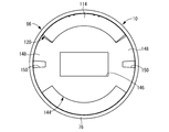
- a presser fitting 144 is disposed on the opening side of the cored bar 66 relative to the inner case member 82.
- the presser fitting 144 has a thin disk shape as a whole, and a through hole 146 having a rectangular cross section is formed at the center thereof.
- a pair of fixing pieces 148 and 148 protruding outward in the radial direction are provided on the presser fitting 144 at positions facing each other across the center of the presser fitting 144.
- Each fixed piece 148 has a notch 150 at the center in the circumferential direction. This facilitates bending deformation of the fixed piece 148 in the thickness direction, and facilitates the work of fitting the presser fitting 144 into the cylindrical wall 68 of the cored bar 66 as will be described later.
- the separation distance on one side in the circumferential direction and the separation distance on the other side in the circumferential direction of the pair of fixed pieces 148 and 148 are the same. This facilitates the positioning of the presser fitting 144 in the circumferential direction when the presser fitting 144 is fitted into the cylindrical wall 68 of the cored bar 66 as will be described later.
- Such a presser fitting 144 is a state in which the inner case member 82 is accommodated in the cored bar 66 and the holding protrusion 120 is positioned between the pair of fixing pieces 148 and 148 in the circumferential direction. It is inserted into 66 cylindrical walls 68. At this time, each of the pair of fixing pieces 148 and 148 is in sliding contact with the cylindrical wall 68 of the core metal 66, and the presser fitting 144 is press-fitted and fixed to the core metal 66 at the pair of fixing pieces 148 and 148.
- the inner case member 82 is sandwiched between the presser fitting 144 and the bottom wall 70 of the core metal 66 in a state where the holding projection 120 protrudes from the presser fitting 144 toward the opening side of the core metal 66, and the core metal 66.
- maintenance protrusion 120 has opposed the magnetized rotor 58 on both sides of the deep bottom part 114.
- the external conductor 130 extends to the outside from the insertion hole 72 of the cored bar 66.
- a sealing member 152 is fixed to the outer peripheral surface of the external conducting wire 130, and this sealing member 152 is fitted into the insertion hole 72 of the cored bar 66.
- the sealing member 152 is made of polyamide such as PA612, and is fixed to the outer peripheral surface of the external conductor 130 with good adhesion. As shown in FIGS. 11 and 12, the sealing member 152 has a thick cylindrical shape as a whole.
- An annular step surface 154 that extends in the direction perpendicular to the axis is formed in the middle portion of the sealing member 152 in the axial direction.
- One of the axial directions is a small diameter portion 156 across the step surface 154, and the other is The large diameter portion 158 is used.
- the outer diameter of the large diameter portion 158 is substantially the same as the inner diameter of the insertion hole 72 of the cored bar 66.
- a concave groove 160 is formed in the middle portion in the axial direction of the large-diameter portion 158 so as to open to the outer peripheral surface and extend over the entire circumference with a substantially constant cross-sectional shape.
- a locking projection 162 is integrally formed at the other axial end portion of the large diameter portion 158.
- the locking protrusion 162 has a rectangular block shape as a whole, and an alignment surface 163 is formed on the outer peripheral surface by cutting off one of the square portions when viewed from above.
- the locking projection 162 extends in the axial direction with a size and a cross-sectional shape corresponding to the central hole 94 of the bottom member 84.
- Such a sealing member 152 is fixed to the external conductor 130 in a state of being externally inserted into a portion of the external conductor 130 that extends outward from the inner case member 82.
- the sealing member 152 can be fixed to the external conductor 130 by being molded or separately formed, and then adhered by an adhesive or the like.
- the sealing member 152 fixed to the external conducting wire 130 is inserted into the insertion hole 72 of the core metal 66 by the large diameter portion 158 being fitted into the cylindrical portion 74 of the core metal 66 from the inside of the core metal 66. It is fitted and installed. At that time, a seal rubber 164 composed of an O-ring or the like is disposed in the concave groove 160 of the sealing member 152. Thereby, the space between the cylindrical portion 74 of the cored bar 66 and the large diameter portion 158 of the sealing member 152 is sealed.
- the outer peripheral edge of the locking protrusion 162 of the sealing member 152 is overlapped with the opening peripheral edge of the insertion hole 72 in the bottom wall 70 of the cored bar 66. Thereby, the locking projection 162 of the sealing member 152 is locked to the bottom wall 70 of the core metal 66 from the inside.
- the locking projection 162 of the sealing member 152 is fitted in the central hole 94 in a state where the sealing member 152 is fitted and mounted in the insertion hole 72 of the cored bar 66. Thereby, the rotation of the external conducting wire 130 around the central axis is prevented.
- the large-diameter portion 158 of the sealing member 152 fixed in close contact with the external conductor 130 is fitted into the cylindrical portion 74 of the core metal 66, and from there the external conductor 130 is pulled out of the core metal 66. Thereby, it is possible to sufficiently secure the waterproofness of the portion of the external conductor 130 that is led out to the outside of the cored bar 66.
- a seal rubber 164 accommodated in the concave groove 160 of the large diameter portion 158 seals between the large diameter portion 158 and the cylindrical portion 74.
- a reliable waterproof effect can be exhibited following the change in the gap between the insertion hole 72 of the metal core 66 and the sealing member 152, and the external conductor 130 can be exposed to the outside of the metal core 66.
- the waterproofness of the drawer portion can be further improved.
- the rotation detection sensor 122 and the external conductor 130 are accommodated in the inner case member 82. Thereby, the waterproofness of the rotation detection sensor 122 can be further improved.
- the connecting portion between the lead wires 126 and 126 and the external conductive wire 130 and the external conductive wire 130 are accommodated in the inner case member 82, only the external conductive wire 130 can be pulled out from the cored bar 66. As a result, there is no need to form a large connector fitting portion from the cored bar 66, and the overall size of the wheel speed sensor 10 can be made compact.
- the locking projection 162 is locked from the inside of the cored bar 66 to the opening peripheral edge of the insertion hole 72. Therefore, even if an external force is applied in the direction in which the external conductor 130 is pulled out from the core bar 66, the external conductor 130 can be prevented from being pulled out from the core bar 66. As a result, it is possible to prevent external force from being applied to the connection portion between the lead wires 126 and 126 and the external conductive wire 130 or the rotation detection sensor 122 through the external conductive wire 130.
- the inner case member 82 is clamped and held between the presser fitting 144 press-fitted and fixed to the cylindrical wall 68 of the core metal 66 and the bottom wall 70 of the core metal 66.
- maintenance protrusion 120 and the magnetized rotor 58 can be maintained by the expected magnitude
- a rotation detection sensor having a structure in which a conventionally known Hall IC is resin-molded may be employed, and the inner case member may be omitted by directly fixing to a cored bar.
Landscapes
- Physics & Mathematics (AREA)
- General Physics & Mathematics (AREA)
- Engineering & Computer Science (AREA)
- General Engineering & Computer Science (AREA)
- Mechanical Engineering (AREA)
- Transmission And Conversion Of Sensor Element Output (AREA)
Abstract
Description
Claims (5)
- 車輪に取り付けられる内側部材を回転可能に支持して車輪軸受装置を構成する外側部材に固着される芯金に対して回転検出センサを取り付ける一方、該回転検出センサの検出部を前記内側部材に設けた着磁ロータに対向させて、該着磁ロータの回転による磁界変動を前記検出部で検出するようになっている回転検出装置において、
前記芯金で覆われた内部空間に前記回転検出センサが収容配置されて前記芯金で支持されていると共に、前記回転検出センサの前記検出部から延び出すリード線が外部導線と電気的に接続されており、前記芯金に形成された挿通孔を通じて前記外部導線が前記内部空間から外部に引き出されている一方、前記外部導線の外周面上にシーリング部材が固着されており、前記芯金に形成された前記挿通孔に対して前記シーリング部材が嵌合装着されていることを特徴とする回転検出装置。 - 前記芯金の前記挿通孔と前記シーリング部材の嵌合部分にそれらの間を封止するシールゴムが配設されている請求項1に記載の回転検出装置。
- 前記シーリング部材には、前記芯金の前記挿通孔よりも大きな係止突部が一体形成されており、該係止突部が前記芯金に対して前記内部空間側から係止されている請求項1又は2に記載の回転検出装置。
- 前記芯金がカップ形状とされており、その開口部分が前記外側部材に固着されて覆蓋されることで前記芯金の内部に前記内部空間が形成されていると共に、前記芯金には内側ケース部材が固定的に取り付けられており、前記内側ケース部材の内部に前記検出部と前記外部導線が組み付けられている請求項1~3の何れか1項に記載の回転検出装置。
- 前記芯金には前記内側ケース部材の外側から押え金具が嵌め入れられて前記芯金に圧入固定されており、前記押え金具によって前記内側ケース部材が前記芯金に固定されている請求項4に記載の回転検出装置。
Priority Applications (3)
| Application Number | Priority Date | Filing Date | Title |
|---|---|---|---|
| US13/393,689 US8833166B2 (en) | 2009-09-01 | 2010-02-23 | Rotation detecting apparatus |
| CN201080038545.1A CN102549388B (zh) | 2009-09-01 | 2010-02-23 | 旋转检测装置 |
| DE112010003511.3T DE112010003511B4 (de) | 2009-09-01 | 2010-02-23 | Dreherkennungsvorrichtung |
Applications Claiming Priority (2)
| Application Number | Priority Date | Filing Date | Title |
|---|---|---|---|
| JP2009201546A JP2011053053A (ja) | 2009-09-01 | 2009-09-01 | 回転検出装置 |
| JP2009-201546 | 2009-09-01 |
Publications (1)
| Publication Number | Publication Date |
|---|---|
| WO2011027482A1 true WO2011027482A1 (ja) | 2011-03-10 |
Family
ID=43649043
Family Applications (1)
| Application Number | Title | Priority Date | Filing Date |
|---|---|---|---|
| PCT/JP2010/001212 Ceased WO2011027482A1 (ja) | 2009-09-01 | 2010-02-23 | 回転検出装置 |
Country Status (5)
| Country | Link |
|---|---|
| US (1) | US8833166B2 (ja) |
| JP (1) | JP2011053053A (ja) |
| CN (1) | CN102549388B (ja) |
| DE (1) | DE112010003511B4 (ja) |
| WO (1) | WO2011027482A1 (ja) |
Families Citing this family (7)
| Publication number | Priority date | Publication date | Assignee | Title |
|---|---|---|---|---|
| JP2017090288A (ja) * | 2015-11-12 | 2017-05-25 | 川崎重工業株式会社 | チェンジドラムの回転位置検出装置及び自動二輪車 |
| JP6669478B2 (ja) * | 2015-11-27 | 2020-03-18 | 川崎重工業株式会社 | 回転検出装置 |
| FR3057630B1 (fr) * | 2016-10-13 | 2020-11-20 | Safran Landing Systems | Procede de liaison entre l'arbre d'un tachymetre et une roue d'aeronef |
| DE102017218878A1 (de) * | 2016-11-07 | 2018-05-24 | Aktiebolaget Skf | Verkabeltes Lager |
| KR20180108238A (ko) * | 2017-03-24 | 2018-10-04 | 주식회사 일진글로벌 | 휠 속도 검출 장치 |
| JP7250535B2 (ja) * | 2019-01-25 | 2023-04-03 | 日本電産サンキョー株式会社 | エンコーダおよびエンコーダ付きモータ |
| CN113937961A (zh) * | 2021-10-22 | 2022-01-14 | 上海汽车变速器有限公司 | 一种电机的测温系统 |
Citations (3)
| Publication number | Priority date | Publication date | Assignee | Title |
|---|---|---|---|---|
| JP2007010480A (ja) * | 2005-06-30 | 2007-01-18 | Ntn Corp | 回転速度検出装置付き車輪用軸受装置 |
| JP2007333169A (ja) * | 2006-06-19 | 2007-12-27 | Nsk Ltd | センサ付軸受装置 |
| JP2008241627A (ja) * | 2007-03-28 | 2008-10-09 | Nsk Ltd | 回転センサ付きカバー及びその製造方法、並びに車輪支持用軸受ユニット |
Family Cites Families (26)
| Publication number | Priority date | Publication date | Assignee | Title |
|---|---|---|---|---|
| JP2551705Y2 (ja) * | 1991-12-26 | 1997-10-27 | エヌティエヌ株式会社 | 車輪用軸受の回転速度検出装置 |
| JP3315443B2 (ja) * | 1992-09-02 | 2002-08-19 | 住友電気工業株式会社 | 自動車用車輪速センサ装置 |
| FR2722343B1 (fr) * | 1994-07-08 | 1996-09-06 | Skf France | Dispositif de connexion pour capteur d'informations associe a un roulement et procede de montage d'un moyeu de roue equipe d'un tel dispositif de connexion |
| JP3312531B2 (ja) * | 1994-07-18 | 2002-08-12 | 日本精工株式会社 | 回転速度検出装置付ハブユニット |
| US6053046A (en) * | 1995-02-09 | 2000-04-25 | Denso Corporation | Rotational speed detector for vehicle wheel with sensor device and integrally formed axle cover |
| JP3079528B2 (ja) * | 1996-02-28 | 2000-08-21 | 日本精機株式会社 | 回転検出装置 |
| FR2751707B1 (fr) * | 1996-07-24 | 1998-09-11 | Skf France | Roulement a capteur d'informations |
| JP3423566B2 (ja) * | 1997-02-26 | 2003-07-07 | 三菱電機株式会社 | 磁気センサ |
| US5975761A (en) * | 1997-03-31 | 1999-11-02 | Nsk Ltd. | Rolling bearing unit with rotational speed sensor |
| US6205858B1 (en) * | 1999-11-24 | 2001-03-27 | Delphi Technologies, Inc. | Vehicle speed sensor |
| IT249389Y1 (it) * | 2000-05-30 | 2003-05-07 | Marchioro Spa Stampaggio Mater | Struttura di giunzione per elementi tubolari disposti a perpendicolo. |
| JP4578015B2 (ja) * | 2000-05-31 | 2010-11-10 | 株式会社ジェイテクト | 密封装置ならびに軸受装置 |
| JP4432231B2 (ja) * | 2000-07-31 | 2010-03-17 | 株式会社デンソー | 回転検出装置 |
| US6564635B2 (en) * | 2001-09-14 | 2003-05-20 | Pete D. Sherman | Bearing assembly with integral sensor for sensing rotation |
| EP1329727A1 (en) * | 2001-10-18 | 2003-07-23 | Nsk Ltd | Rotation-speed sensor device |
| CN1289911C (zh) * | 2002-03-08 | 2006-12-13 | Ntn株式会社 | 旋转检测器和采用它的防锁制动装置 |
| US7305765B2 (en) * | 2002-10-18 | 2007-12-11 | Nsk Ltd. | Bearing unit for wheel and method of manufacturing the bearing unit |
| DE60324086D1 (de) * | 2002-12-24 | 2008-11-27 | Jtekt Corp | Wälzlagervorrichtung mit Sensor |
| JP4179083B2 (ja) | 2003-07-08 | 2008-11-12 | 株式会社デンソー | 回転検出装置 |
| US7141966B2 (en) * | 2004-07-01 | 2006-11-28 | Denso Corporation | Rotation detecting apparatus |
| FR2885699B1 (fr) * | 2005-05-13 | 2007-08-24 | Messier Bugatti Sa | Dispositif d'accouplement en rotation d'une roue d'avion et d'un tachymetre. |
| JP2006335318A (ja) * | 2005-06-06 | 2006-12-14 | Alps Electric Co Ltd | 回転コネクタと舵角センサの連結構造 |
| US7401800B2 (en) * | 2005-09-14 | 2008-07-22 | Slam Corporation | Gas spring suspension system |
| US8253412B2 (en) * | 2005-09-30 | 2012-08-28 | Nippon Seiki Co., Ltd. | Rotation detector for a wheeled vehicle |
| JP2008116267A (ja) * | 2006-11-02 | 2008-05-22 | Jtekt Corp | 着磁パルサリング |
| JP2008180617A (ja) * | 2007-01-25 | 2008-08-07 | Ntn Corp | 回転速度検出装置付き車輪用軸受装置 |
-
2009
- 2009-09-01 JP JP2009201546A patent/JP2011053053A/ja not_active Abandoned
-
2010
- 2010-02-23 DE DE112010003511.3T patent/DE112010003511B4/de not_active Expired - Fee Related
- 2010-02-23 WO PCT/JP2010/001212 patent/WO2011027482A1/ja not_active Ceased
- 2010-02-23 CN CN201080038545.1A patent/CN102549388B/zh not_active Expired - Fee Related
- 2010-02-23 US US13/393,689 patent/US8833166B2/en not_active Expired - Fee Related
Patent Citations (3)
| Publication number | Priority date | Publication date | Assignee | Title |
|---|---|---|---|---|
| JP2007010480A (ja) * | 2005-06-30 | 2007-01-18 | Ntn Corp | 回転速度検出装置付き車輪用軸受装置 |
| JP2007333169A (ja) * | 2006-06-19 | 2007-12-27 | Nsk Ltd | センサ付軸受装置 |
| JP2008241627A (ja) * | 2007-03-28 | 2008-10-09 | Nsk Ltd | 回転センサ付きカバー及びその製造方法、並びに車輪支持用軸受ユニット |
Also Published As
| Publication number | Publication date |
|---|---|
| JP2011053053A (ja) | 2011-03-17 |
| CN102549388B (zh) | 2015-04-15 |
| DE112010003511T5 (de) | 2012-08-30 |
| DE112010003511B4 (de) | 2014-06-05 |
| US8833166B2 (en) | 2014-09-16 |
| CN102549388A (zh) | 2012-07-04 |
| US20120160026A1 (en) | 2012-06-28 |
Similar Documents
| Publication | Publication Date | Title |
|---|---|---|
| JP6578642B2 (ja) | モータ | |
| US7509883B2 (en) | Torque detecting apparatus and manufacturing method thereof | |
| EP2913679B1 (en) | Bearing apparatus with sensor and rolling bearing with sensor | |
| JP2011053053A (ja) | 回転検出装置 | |
| JP6520033B2 (ja) | モータ | |
| US10101412B2 (en) | Sensing device and method for manufacturing sensing device | |
| US20120013329A1 (en) | Rotation sensor device for wheel | |
| JP2009002723A (ja) | 回転検出センサ | |
| CN111556955A (zh) | 感测装置 | |
| WO2005078457A1 (ja) | センサ付軸受装置 | |
| JP2007085906A (ja) | 回転検出センサの取付構造 | |
| JP4916987B2 (ja) | 回転検出センサ | |
| JP2010142053A (ja) | ブラシレスモータ | |
| JP2009261149A (ja) | ブラシレスモータ | |
| JP2008241557A (ja) | 回転検出センサ | |
| JP4916986B2 (ja) | 回転検出センサ | |
| JP2010043889A (ja) | 回転検出センサ | |
| CN213279427U (zh) | 电动致动器 | |
| JP5063231B2 (ja) | 回転検出センサ・固定部材取付体 | |
| JP2017143684A (ja) | 回転電機 | |
| JP2008275490A (ja) | 回転検出センサ | |
| KR20180051150A (ko) | 센서 조립체 및 이를 포함하는 조향 장치 | |
| JP2009025063A (ja) | 回転検出センサ | |
| KR20180085494A (ko) | 로터 위치 감지장치 및 이를 포함하는 모터 | |
| JP2009025061A (ja) | 回転検出センサ |
Legal Events
| Date | Code | Title | Description |
|---|---|---|---|
| WWE | Wipo information: entry into national phase |
Ref document number: 201080038545.1 Country of ref document: CN |
|
| 121 | Ep: the epo has been informed by wipo that ep was designated in this application |
Ref document number: 10813438 Country of ref document: EP Kind code of ref document: A1 |
|
| WWE | Wipo information: entry into national phase |
Ref document number: 13393689 Country of ref document: US Ref document number: 112010003511 Country of ref document: DE Ref document number: 1120100035113 Country of ref document: DE |
|
| 122 | Ep: pct application non-entry in european phase |
Ref document number: 10813438 Country of ref document: EP Kind code of ref document: A1 |