WO2011021621A1 - 金属管の引抜装置および引抜方法 - Google Patents
金属管の引抜装置および引抜方法 Download PDFInfo
- Publication number
- WO2011021621A1 WO2011021621A1 PCT/JP2010/063854 JP2010063854W WO2011021621A1 WO 2011021621 A1 WO2011021621 A1 WO 2011021621A1 JP 2010063854 W JP2010063854 W JP 2010063854W WO 2011021621 A1 WO2011021621 A1 WO 2011021621A1
- Authority
- WO
- WIPO (PCT)
- Prior art keywords
- lubricating oil
- discharge port
- rod
- pipe
- drawing device
- Prior art date
- Legal status (The legal status is an assumption and is not a legal conclusion. Google has not performed a legal analysis and makes no representation as to the accuracy of the status listed.)
- Ceased
Links
Images


Classifications
-
- B—PERFORMING OPERATIONS; TRANSPORTING
- B21—MECHANICAL METAL-WORKING WITHOUT ESSENTIALLY REMOVING MATERIAL; PUNCHING METAL
- B21C—MANUFACTURE OF METAL SHEETS, WIRE, RODS, TUBES, PROFILES OR LIKE SEMI-MANUFACTURED PRODUCTS OTHERWISE THAN BY ROLLING; AUXILIARY OPERATIONS USED IN CONNECTION WITH METAL-WORKING WITHOUT ESSENTIALLY REMOVING MATERIAL
- B21C9/00—Cooling, heating or lubricating drawing material
-
- B—PERFORMING OPERATIONS; TRANSPORTING
- B21—MECHANICAL METAL-WORKING WITHOUT ESSENTIALLY REMOVING MATERIAL; PUNCHING METAL
- B21C—MANUFACTURE OF METAL SHEETS, WIRE, RODS, TUBES, PROFILES OR LIKE SEMI-MANUFACTURED PRODUCTS OTHERWISE THAN BY ROLLING; AUXILIARY OPERATIONS USED IN CONNECTION WITH METAL-WORKING WITHOUT ESSENTIALLY REMOVING MATERIAL
- B21C1/00—Manufacture of metal sheets, wire, rods, tubes or like semi-manufactured products by drawing
- B21C1/16—Metal drawing by machines or apparatus in which the drawing action is effected by means other than drums, e.g. by a longitudinally-moved carriage pulling or pushing the work or stock for making metal sheets, rods or tubes
- B21C1/22—Metal drawing by machines or apparatus in which the drawing action is effected by means other than drums, e.g. by a longitudinally-moved carriage pulling or pushing the work or stock for making metal sheets, rods or tubes specially adapted for making tubular articles
- B21C1/24—Metal drawing by machines or apparatus in which the drawing action is effected by means other than drums, e.g. by a longitudinally-moved carriage pulling or pushing the work or stock for making metal sheets, rods or tubes specially adapted for making tubular articles by means of mandrels
-
- B—PERFORMING OPERATIONS; TRANSPORTING
- B21—MECHANICAL METAL-WORKING WITHOUT ESSENTIALLY REMOVING MATERIAL; PUNCHING METAL
- B21C—MANUFACTURE OF METAL SHEETS, WIRE, RODS, TUBES, PROFILES OR LIKE SEMI-MANUFACTURED PRODUCTS OTHERWISE THAN BY ROLLING; AUXILIARY OPERATIONS USED IN CONNECTION WITH METAL-WORKING WITHOUT ESSENTIALLY REMOVING MATERIAL
- B21C3/00—Profiling tools for metal drawing; Combinations of dies and mandrels for metal drawing
- B21C3/16—Mandrels; Mounting or adjusting same
Definitions
- the present invention is a metal pipe drawing apparatus capable of manufacturing a metal pipe with excellent dimensional accuracy, which is suitably used as a substrate for an OPC photosensitive drum in an electrophotographic apparatus such as a copying machine, a laser beam printer, or a facsimile. And a drawing method using the drawing device. Further, in the description of the present specification, “rear” in the drawing device and the drawing method indicates the direction of the raw pipe side with respect to the drawn pipe, and “forward” indicates the direction of the drawn pipe side with respect to the raw pipe. ing.
- non-cutting tube suitable for mass production has come to be widely used as a substrate for an OPC photosensitive drum in an electrophotographic apparatus such as a copying machine, a laser beam printer, and a facsimile.
- One of the non-cutting pipes is an ED pipe obtained by drawing aluminum extruded raw pipe, which is suitable for mass production in that multiple product pipes can be produced at one drawing, and it responds to mass consumption accompanying market expansion. It is noted as a manufacturing method.
- an aluminum extruded raw pipe is obtained by extruding an aluminum billet, and after the extruded raw pipe is cut into a predetermined length, drawing is performed by one pass or two or more passes using a die and a plug. It is manufactured by obtaining an aluminum tube defined in a predetermined shape (outside diameter, inside diameter, thickness), cutting it, chamfering the end, cleaning it, and inspecting its size and appearance.
- the applicant has provided an opening in the peripheral wall of the hollow rod that supports the plug, and the lubricating oil supplied to the inside from the rear end of the rod is discharged from the opening, and We proposed a drawing device capable of supplying lubricating oil to the inner surface as needed.
- a core is attached to a rod in order to evenly spread the lubricating oil deposited on the inner surface of the pipe of the plug (Patent Documents 1 and 2).
- the supply of lubricating oil is stopped to take out the processed drawn pipe from the apparatus, and the next extruded raw pipe is removed.
- the lubricant supply is resumed when it is set in the device and starts to be withdrawn.
- the step of intermittently supplying the lubricating oil when the supply of the lubricating oil is stopped, the lubricating oil in the rod flows out from the opening.
- the present invention provides an intermittent lubricating oil supply in a metal pipe drawing device that discharges lubricating oil from an opening provided in a hollow rod supporting a plug and adheres to the inner surface of a base pipe. It is an object of the present invention to improve the responsiveness of lubricating oil discharge when performing.
- the metal tube drawing apparatus and drawing method of the present invention have the configurations described in the following [1] to [10].
- a discharge port for discharging lubricating oil is opened on the outer peripheral surface of the hollow rod supporting the plug, and the discharge port is provided only in a region above the center in the vertical direction of the rod Tube puller.
- a metal pipe characterized by repeating the steps (i) to (v) successively using a drawing apparatus according to any one of the preceding items 1 to 9 to draw a plurality of metal base pipes successively. How to pull out.
- Lubricating oil is supplied into the hollow rod supporting the plug and discharged from the discharge port, thereby drawing out the raw pipe while supplying the lubricating oil to the inner surface of the raw pipe, (Ii) stopping the supply of lubricating oil after the drawing of the raw pipe is completed; (Iii) Take out the drawn pipe from the drawing device and set the next raw pipe in the drawing device, (Iv) resume the supply of lubricating oil, (V) Return to (i).
- the discharge port of the lubricating oil is provided only in the upper region of the rod, the lubricating oil filled inside the rod is discharged from the discharge port even if the lubricating oil supply is stopped. It does not flow out, or only a small amount if it flows out, and the inside of the rod is filled with the lubricating oil or almost completely filled even while the supply of lubricating oil is stopped. Therefore, even if the supply of lubricating oil is stopped before the extraction pipe is removed from the device and the next element pipe is set in the device after the extraction of one raw pipe is completed, the inside of the rod is lubricated with lubricating oil.
- the lubricating oil can be discharged from the discharge port immediately or in a very short time. Therefore, in the continuous drawing process of a plurality of element pipes, when intermittent lubricating oil supply is performed to stop the lubricating oil supply at the time of element pipe replacement, the lubricating oil is reliably attached from the start of drawing of each element pipe Can prevent burn-in. In addition, since it is not necessary to wait for the recovery of the discharge amount after the lubricating oil supply is resumed, efficient processing can be performed.
- the discharge position of the lubricating oil approaches the base pipe when the nozzle protrudes from the outer peripheral surface of the rod, the inner diameter of the base pipe is larger than the rod diameter Also, even when the amount of discharge is small, it can be reliably attached to the desired position. Furthermore, since the nozzle is wrinkled when oil supply is stopped, it is possible to prevent the outflow from the discharge port provided at a position other than the top.
- the lubricating oil can be sprayed forward of the position of the discharge port, and the distance from the spraying position to the bearing portion of the plug becomes short. Therefore, the lubricating oil can be reliably adhered to the upper region of the hollow shell where the lubricating oil tends to run short in the bearing portion.
- the amount of lubricating oil flowing out from the discharge port at the time of lubricating oil supply stop is small, and the responsiveness at the time of resupplying is good.
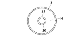
- FIG. 2 is a cross-sectional view of a raw pipe and a rod in the drawing device of FIG. 1; It is a cross-sectional view which shows the other aspect of the rod in the drawing-out apparatus of this invention. It is a cross-sectional view which shows the other aspect of the rod in the drawing-out apparatus of this invention. It is a cross-sectional view which shows the other aspect of the rod in the drawing-out apparatus of this invention. It is a longitudinal cross-sectional view which shows the other aspect of the rod in the drawing-out apparatus of this invention.
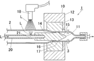
- FIG. 1 is an example of a drawing apparatus for carrying out the metal pipe drawing method of the present invention.
- the drawing device (1) includes a drawing tool and a lubricating oil supply unit for supplying a lubricating oil to the outer surface and the inner surface of the raw pipe (2).
- the drawing tool comprises a drawing die (10) and a plug (11).
- the drawing die (10) comprises a die body (13) fitted in a die case (12), the die body (13) following the approach portion (14) around a central die hole And a bearing portion (15).
- the plug (11) is attached to and supported by the tip of a hollow tube rod (20), and has an approach portion (16) and a bearing portion (17) following it.
- the base pipe (2) is drawn between the drawing die (10) and the plug (11), whereby the outer surface of the pipe is formed by the bearing portion (15) of the die main body (13). Are molded by the bearing portion (17) of the plug (11) to produce the drawn pipe (3).
- a nozzle (18) is disposed above the rear of the drawing die (10) as a lubricating oil supply unit for the outer surface.
- the lubricating oil (L) supplied from the tank outside the figure is discharged from the nozzle (18) toward the raw pipe (2), and the lubricating oil (L) adhering to the upper portion of the raw pipe (2) travels along the outer surface It is supplied all around, and excess lubricating oil (L) flows down. Then, the base pipe (2) is introduced into the drawing tool with the lubricating oil (L) attached to the outer surface.
- the rod (20) is provided with a lubricant oil discharge port (21) as a lubricant oil supply unit for the inner surface.
- the rod (20) is a hollow tube and is used as a supply passage for lubricating oil (L), and a discharge port (21) communicating with the supply passage is formed by drilling a peripheral wall.
- one discharge port (21) is formed at the top of the rod (20) (highest position in the vertical direction) so as to open upward.
- the lubricating oil (L) introduced into the interior from the rear of the rod (20) from the tank (not shown) is discharged from the discharge port (21) and sprayed to adhere to the upper surface of the base pipe (2). It spreads in the circumferential direction along the wall.
- the raw pipe (2) is introduced into the drawing tool in a state where the lubricating oil (L) adheres to the entire inner surface. If lubricating oil (L) is continuously discharged from the discharge port (21) during drawing, the required amount of lubricating oil (L) can be adhered regardless of the length of the raw pipe (2).
- step (v) is a waiting period for replenishing the outflow and waiting for the recovery of the discharge amount.
- the discharge port is provided only in the region above the center in the vertical direction of the rod, and not in the region below the center and the center.
- the discharge port is provided only in the region above the center in the vertical direction of the rod, the number and the position thereof are not limited.
- the present invention also includes the case where a plurality of discharge ports are provided along the circumferential direction or the drawing direction.
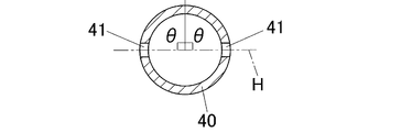
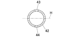
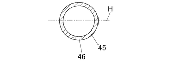
- (H) shows a horizontal plane passing through the centers of the rods (20) (22) (24) (25) (29).
- the area above the horizontal plane (H) is the area where the discharge ports can be installed, and the number and the position of the discharge ports can be arbitrarily provided within this area.
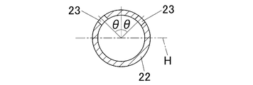
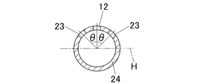
- the position of the discharge port in the circumferential direction is represented by an angle ( ⁇ ) from the top of the rod to the center of the rod.
- the condition of the angle ( ⁇ ) is ⁇ ⁇ 90 °, and within this range, it may be appropriately set according to the inner diameter of the raw pipe, the spray area from the discharge port, the discharge amount and the like.
- the rod (22) in FIG. 3 is an example in which two discharge ports (23) and (23) are provided at a position lowered from the top in the circumferential direction, that is, a position satisfying 0 ° ⁇ ⁇ 90 °.
- the discharge port (23) may be provided in the range where the angle ( ⁇ ) is 60 ° or less (including 60 °). In particular, it is preferable to set it in the range of 40 ° or less (including 40 °). This is because the position of the discharge port (23) decreases as the angle ( ⁇ ) increases, and the outflow amount at the time of stopping the supply of lubricating oil increases, so that the responsiveness at the time of resupply decreases.
- the discharge port is provided at a position close to the bearing portion of the plug in the drawing direction. Since the discharge port (21) is provided in the upper area of the rod (20), the lubricating oil (L) is sprayed and attached to the upper area of the raw pipe (2), but the raw pipe (2) The lubricating oil (L) also flows downward while moving from the position 21) to the position of the bearing portion (17) of the plug (11).
- the lubricating oil (L) is sequentially sent to the rear of the base pipe (2) and flows downward, except for the one which is pulled out with the drawing pipe (3), the lubricating oil shortage is caused by the raw pipe (2) Is likely to occur in the upper region of With respect to the flow of such lubricating oil (L), the position of the discharge port (21) is brought close to the bearing portion (17), and the distance from the spraying position of the lubricating oil (L) to the bearing portion (17) is shortened.
- the lubricating oil (L) can be reliably attached to the upper region where the lubricating oil (L) tends to run short in the bearing portion (17), and the lubricating oil (L) is efficiently applied to the inner surface of the base pipe (2) Can be attached.
- the discharge port (21) is preferably provided at a position of 20 cm or less (including 20 cm) from the bearing portion (17), and particularly preferably at a position of 10 cm or less (including 10 cm).
- the present invention also includes the case where the discharge port is provided in the overlapping portion of the two. .
- the spray position can be brought close to the bearing portion (17).
- the spray position can be further brought closer to the bearing portion.
- the rod (27) in FIG. 6 is formed by piercing the peripheral wall obliquely and opening the discharge port (28) forward.
- the rod (29) in FIG. 7 is one in which the nozzle (30) is attached to the discharge port (28) having a circumferential wall with the nozzle (30) directed forward.
- Lubricant oil can be supplied to the outer surface of the base pipe by a known method such as providing the above-mentioned lubricant oil discharge nozzle (18) behind the drawing tool. Further, the lubricating oil does not necessarily have to be supplied while being drawn, and the lubricating oil may be applied to the entire outer surface of the blank before drawing. Since the outer surface is not subject to positional limitations as in the inner surface, the lubricating oil can be supplied even during the drawing and before the drawing, and the drawing can be carried out without running out of the lubricating oil.
- the discharge port of the lubricating oil is provided only in the upper region of the rod, so even if the supply of lubricating oil is stopped The lubricating oil does not flow out of the discharge port or is a small amount even if it flows out. That is, even while the supply of lubricating oil is stopped, the inside of the rod is filled with lubricating oil or is almost filled with lubricating oil. For this reason, in the process of continuously pulling out a plurality of raw pipes, after the drawing of one raw pipe is completed, the drawing pipe is taken out of the apparatus before the next raw pipe is set in the apparatus.
- the present invention does not limit the length of the raw pipe, it is possible to ensure the lubricity of the inner surface by applying lubricating oil to the plug before drawing out as in the prior art for a short raw pipe. It has a remarkable effect when drawing out a pipe and is suitable for drawing out a long raw pipe. Specifically, a remarkable effect can be obtained for an element tube of 2 m or more, particularly 2.5 m or more.
- the metal tube drawing method of the present invention is not limited to the type of metal, and can be widely applied to aluminum, iron, copper, or alloys thereof. Since a remarkable effect is obtained when pulling out a long raw pipe, it is suitable for manufacturing an aluminum pipe for a photosensitive drum substrate. In the production of aluminum tubes for photosensitive drum substrates, there is a tendency to use long raw tubes in order to produce a large number of product tubes in a single drawing, and by applying the drawing method of the present invention, high quality with less distortion Aluminum tube can be manufactured efficiently. In addition, even when continuous drawing is performed in two or more passes in order to improve dimensional accuracy, it is not necessary to perform an inter-pass operation for lubricating oil supply, and therefore, rapid continuous drawing can be performed. Further, as a material of the aluminum tube for the photosensitive drum substrate, an Al-Mn based alloy, an Al-Mg based alloy, an Al-Mg-Si based alloy, and pure aluminum can be exemplified.
- the approach angle of the approach portion (14) of the die body (13) of the drawing die (10) is 15 °, and the bearing length of the bearing portion (15) is 15 mm. Further, the approach angle of the approach portion (16) of the plug (11) is 7 °, and the bearing length of the bearing portion (17) is 2 mm.
- a nozzle (18) as a common lubricating oil supply unit for the outer surface is disposed at the upper rear of the drawing die (10).
- lubricating oil (L) supplied from a tank (not shown) is discharged from the nozzle (18), supplied to the upper surface side of the raw pipe (2), and supplied to the entire circumference along the outer surface.
- Lubricant oil is supplied to the inner surface of the base pipe (2) through the discharge port formed in the rod, and the lubricating oil (L) introduced into the rod from behind is ejected from each discharge port to It was sprayed on the inner surface of 2).
- Strool ES150 (viscosity: 1.4 ⁇ 10 ⁇ 4 m 2 / s) manufactured by Kyoei Oil Co., Ltd. was used.
- the position and the number in the circumferential direction of the discharge port are as shown in Table 1.
- the position of the discharge port in the circumferential direction is indicated by the angle ( ⁇ ) from the top of the rod to the center of the rod.
- the position of the discharge port in the longitudinal direction of the rod is 10 cm rearward from the bearing portion (17) of the plug (11) and is common to each example.
- Example 5 As shown in FIG.
- aluminum alloy (Mn: 1.12 mass%, Si: 0.11 mass%, Fe: 0.39 mass%, Cu: 0.16 mass%, Zn: 0.01 mass%, Mg: A billet containing 0.02% by mass, the balance being aluminum and unavoidable impurities) is extruded at an extrusion temperature of 520 ° C. under a condition of an extrusion speed of 5 m / min, extruding a cylindrical tube having an outer diameter of 32 mm and a wall thickness of 1.5 mm The tube cut to 2 m was used as a test tube (2).
- the drawing process is performed at a drawing speed of 30 m / min, an outer diameter reduction rate of 16%, and a cross-sectional area reduction rate of 32% while supplying lubricating oil to the outer surface and the inner surface of the raw pipe (2) Was processed continuously.
- a drawing speed of 30 m / min, an outer diameter reduction rate of 16%, and a cross-sectional area reduction rate of 32%
- supply of lubricating oil to the inner and outer surfaces is stopped, the drawn pipe is taken out from the drawing device, and the next raw pipe is set in the drawing apparatus. And immediately started drawing and lubricating oil supply. That is, in a plurality of continuous drawing processes, the interruption time of the process is made to be shortest.
- the drawn tube (3) processed in each example was transferred from the drawing device (1) to the conveyer, allowed to cool to room temperature, and cut into a length of 260 mm.
- the inner surface was visually observed and evaluated according to the following criteria. The evaluation results are shown in Table 1.
- the present application relates to claim priority of Japanese Patent Application No. 2009-188827 filed on Aug. 18, 2009, and the disclosure content thereof constitutes a part of the present application as it is.
- the lubricating oil can be applied to the inner surface of the raw pipe reliably and efficiently in the continuous drawing of a plurality of raw pipes, it is suitable for mass production of aluminum pipes for photosensitive drum substrates There is.
Landscapes
- Engineering & Computer Science (AREA)
- Mechanical Engineering (AREA)
- Metal Extraction Processes (AREA)
Priority Applications (2)
| Application Number | Priority Date | Filing Date | Title |
|---|---|---|---|
| US13/389,600 US20120198901A1 (en) | 2009-08-18 | 2010-08-17 | Apparatus and method for drawing metal tube |
| CN201080036898.8A CN102470415B (zh) | 2009-08-18 | 2010-08-17 | 金属管的拉拔装置及拉拔方法 |
Applications Claiming Priority (2)
| Application Number | Priority Date | Filing Date | Title |
|---|---|---|---|
| JP2009188827A JP5280971B2 (ja) | 2009-08-18 | 2009-08-18 | 金属管の引抜装置および引抜方法 |
| JP2009-188827 | 2009-08-18 |
Publications (1)
| Publication Number | Publication Date |
|---|---|
| WO2011021621A1 true WO2011021621A1 (ja) | 2011-02-24 |
Family
ID=43607072
Family Applications (1)
| Application Number | Title | Priority Date | Filing Date |
|---|---|---|---|
| PCT/JP2010/063854 Ceased WO2011021621A1 (ja) | 2009-08-18 | 2010-08-17 | 金属管の引抜装置および引抜方法 |
Country Status (4)
| Country | Link |
|---|---|
| US (1) | US20120198901A1 (https=) |
| JP (1) | JP5280971B2 (https=) |
| CN (1) | CN102470415B (https=) |
| WO (1) | WO2011021621A1 (https=) |
Cited By (2)
| Publication number | Priority date | Publication date | Assignee | Title |
|---|---|---|---|---|
| US9339606B2 (en) | 2014-05-15 | 2016-05-17 | West Pharmaceutical Services, Inc. | Foldable finger flange for a syringe |
| US10064997B2 (en) | 2014-10-09 | 2018-09-04 | West Pharmaceutical Services, Inc. | Rotatable finger flange for a syringe |
Families Citing this family (8)
| Publication number | Priority date | Publication date | Assignee | Title |
|---|---|---|---|---|
| JP5749605B2 (ja) * | 2011-08-26 | 2015-07-15 | 昭和電工株式会社 | 金属管の引抜方法及び引抜装置 |
| JP5781399B2 (ja) * | 2011-08-30 | 2015-09-24 | 昭和電工株式会社 | 金属管の引抜装置及び引抜方法 |
| CN107504354B (zh) * | 2015-09-12 | 2019-06-04 | 太仓升达机械有限公司 | 一种管材拉拔内腔加油装置的工作方法 |
| CN105127223A (zh) * | 2015-10-10 | 2015-12-09 | 安陆火凤凰铝材有限责任公司 | 一种铝管拉拔油润滑装置 |
| DE102017202723B4 (de) * | 2016-07-22 | 2024-05-08 | Sms Group Gmbh | Vorrichtung zur Vorbereitung eines Rohrendes zum Gleitziehen |
| CN109433840B (zh) * | 2018-12-10 | 2023-09-12 | 江苏宏宝优特管业制造有限公司 | 拉拔机内外管壁润滑机构及润滑方法 |
| US11134760B2 (en) * | 2019-06-27 | 2021-10-05 | Titan Company Limited | System and method for manufacturing hollow tubular jewellery |
| CN113458166B (zh) * | 2021-06-30 | 2023-04-21 | 北京科技大学 | 一种带螺旋肋包壳管的冷拔成形装置及成形方法 |
Citations (3)
| Publication number | Priority date | Publication date | Assignee | Title |
|---|---|---|---|---|
| JPS508117A (https=) * | 1973-05-25 | 1975-01-28 | ||
| JPS5089950U (https=) * | 1973-12-22 | 1975-07-30 | ||
| JPH0716642A (ja) * | 1993-07-06 | 1995-01-20 | Nippon Steel Corp | ステンレス鋼管の経済的冷牽方法 |
Family Cites Families (4)
| Publication number | Priority date | Publication date | Assignee | Title |
|---|---|---|---|---|
| US1374369A (en) * | 1919-03-29 | 1921-04-12 | Luther D Earl | Tool for piercing billets |
| US2173099A (en) * | 1937-01-28 | 1939-09-19 | Vascoloy Ramet Corp | Means and method of tube drawing |
| CN1406681A (zh) * | 2001-08-30 | 2003-04-02 | 隆昌山川精密焊管有限责任公司 | 轿、微车磁电机外壳用电焊冷拔精密管 |
| CN100366355C (zh) * | 2006-01-23 | 2008-02-06 | 太原科技大学 | 液压柔性冷拔管的方法及其设备 |
-
2009
- 2009-08-18 JP JP2009188827A patent/JP5280971B2/ja not_active Expired - Fee Related
-
2010
- 2010-08-17 US US13/389,600 patent/US20120198901A1/en not_active Abandoned
- 2010-08-17 CN CN201080036898.8A patent/CN102470415B/zh not_active Expired - Fee Related
- 2010-08-17 WO PCT/JP2010/063854 patent/WO2011021621A1/ja not_active Ceased
Patent Citations (3)
| Publication number | Priority date | Publication date | Assignee | Title |
|---|---|---|---|---|
| JPS508117A (https=) * | 1973-05-25 | 1975-01-28 | ||
| JPS5089950U (https=) * | 1973-12-22 | 1975-07-30 | ||
| JPH0716642A (ja) * | 1993-07-06 | 1995-01-20 | Nippon Steel Corp | ステンレス鋼管の経済的冷牽方法 |
Cited By (2)
| Publication number | Priority date | Publication date | Assignee | Title |
|---|---|---|---|---|
| US9339606B2 (en) | 2014-05-15 | 2016-05-17 | West Pharmaceutical Services, Inc. | Foldable finger flange for a syringe |
| US10064997B2 (en) | 2014-10-09 | 2018-09-04 | West Pharmaceutical Services, Inc. | Rotatable finger flange for a syringe |
Also Published As
| Publication number | Publication date |
|---|---|
| JP5280971B2 (ja) | 2013-09-04 |
| JP2011036904A (ja) | 2011-02-24 |
| CN102470415B (zh) | 2014-12-10 |
| US20120198901A1 (en) | 2012-08-09 |
| CN102470415A (zh) | 2012-05-23 |
Similar Documents
| Publication | Publication Date | Title |
|---|---|---|
| WO2011021621A1 (ja) | 金属管の引抜装置および引抜方法 | |
| JP5426701B2 (ja) | 金属管の引抜装置および引抜方法 | |
| JP2009045663A (ja) | 金属管の引抜装置および引抜方法 | |
| JP5154851B2 (ja) | 金属管の引抜装置および引抜方法 | |
| JP2012055955A (ja) | 冷間圧延における圧延潤滑方法およびその装置 | |
| JP5781399B2 (ja) | 金属管の引抜装置及び引抜方法 | |
| JP5512341B2 (ja) | 金属管の引抜方法 | |
| JP5669739B2 (ja) | 金属めっき鋼管の製造方法及び製造システム | |
| JP5661494B2 (ja) | 金属管の引抜方法及び引抜装置 | |
| JP5819145B2 (ja) | 金属管の引抜方法及び引抜装置 | |
| JP5149545B2 (ja) | アルミニウム管の製造方法 | |
| JP5819146B2 (ja) | 金属管の引抜方法及び引抜装置 | |
| JP2005099774A (ja) | 表面品質に優れたアルミニウム管及びその製造方法と製造装置並びに感光ドラム基体 | |
| JP5749605B2 (ja) | 金属管の引抜方法及び引抜装置 | |
| JP2007268553A (ja) | マグネシウム合金パイプの製造方法 | |
| JP4967974B2 (ja) | 熱間押出用ガラス潤滑剤、並びにこれを用いる金属材料の熱間押出方法および金属管の製造方法 | |
| JP2765390B2 (ja) | マンドレルミルによる継目無鋼管の圧延方法 | |
| JP2012166241A (ja) | 金属管の引抜方法及び引抜装置 | |
| CN209094195U (zh) | 一种用于生产镀锌管的冷拔模具 | |
| JP2024167878A (ja) | 金属材の製造方法及びその製造方法に用いられる冷間塑性加工装置 | |
| CN204470305U (zh) | 铝护套在线水拉伸模具 | |
| RU2647393C1 (ru) | Способ винтовой прошивки и устройство для его осуществления | |
| JP2010052018A (ja) | 管状ワークの引抜加工方法 | |
| JPH10118710A (ja) | フラックス入りワイヤ伸線用ダイヤモンドダイス | |
| JPH0215819A (ja) | アルミ被覆鋼線の湿式強制潤滑伸線方法 |
Legal Events
| Date | Code | Title | Description |
|---|---|---|---|
| WWE | Wipo information: entry into national phase |
Ref document number: 201080036898.8 Country of ref document: CN |
|
| 121 | Ep: the epo has been informed by wipo that ep was designated in this application |
Ref document number: 10809962 Country of ref document: EP Kind code of ref document: A1 |
|
| NENP | Non-entry into the national phase |
Ref country code: DE |
|
| WWE | Wipo information: entry into national phase |
Ref document number: 13389600 Country of ref document: US |
|
| 122 | Ep: pct application non-entry in european phase |
Ref document number: 10809962 Country of ref document: EP Kind code of ref document: A1 |