WO2011021540A1 - 紙葉類搬送用ローラ - Google Patents
紙葉類搬送用ローラ Download PDFInfo
- Publication number
- WO2011021540A1 WO2011021540A1 PCT/JP2010/063545 JP2010063545W WO2011021540A1 WO 2011021540 A1 WO2011021540 A1 WO 2011021540A1 JP 2010063545 W JP2010063545 W JP 2010063545W WO 2011021540 A1 WO2011021540 A1 WO 2011021540A1
- Authority
- WO
- WIPO (PCT)
- Prior art keywords
- roller
- conductive
- paper sheet
- yarn
- roller body
- Prior art date
- Legal status (The legal status is an assumption and is not a legal conclusion. Google has not performed a legal analysis and makes no representation as to the accuracy of the status listed.)
- Ceased
Links
Images

Classifications
-
- B—PERFORMING OPERATIONS; TRANSPORTING
- B65—CONVEYING; PACKING; STORING; HANDLING THIN OR FILAMENTARY MATERIAL
- B65H—HANDLING THIN OR FILAMENTARY MATERIAL, e.g. SHEETS, WEBS, CABLES
- B65H27/00—Special constructions, e.g. surface features, of feed or guide rollers for webs
-
- B—PERFORMING OPERATIONS; TRANSPORTING
- B65—CONVEYING; PACKING; STORING; HANDLING THIN OR FILAMENTARY MATERIAL
- B65H—HANDLING THIN OR FILAMENTARY MATERIAL, e.g. SHEETS, WEBS, CABLES
- B65H2404/00—Parts for transporting or guiding the handled material
- B65H2404/10—Rollers
- B65H2404/13—Details of longitudinal profile
- B65H2404/135—Body
- B65H2404/1351—Pipe element
-
- B—PERFORMING OPERATIONS; TRANSPORTING
- B65—CONVEYING; PACKING; STORING; HANDLING THIN OR FILAMENTARY MATERIAL
- B65H—HANDLING THIN OR FILAMENTARY MATERIAL, e.g. SHEETS, WEBS, CABLES
- B65H2404/00—Parts for transporting or guiding the handled material
- B65H2404/10—Rollers
- B65H2404/18—Rollers composed of several layers
- B65H2404/186—Rollers composed of several layers with electro-conductive layer
Definitions
- the present invention relates to a paper sheet conveyance roller to which an antistatic function is added, which is used for paper feeding of, for example, a printer, a multifunction machine, a copier, and a fax machine.
- a solid roller configured by inserting a shaft through a roller body formed of rubber is known.
- the roller is used for paper feeding in a printer, a multi-function machine, a copier, a fax machine, and the like, and conveys paper sheets by applying a conveying force by the outer peripheral surface of the roller.
- Such a solid roller for transporting paper sheets needs to be prevented from being charged in order to prevent paper double feed due to static electricity.
- the paper is contaminated with, for example, black by the conductive powder, and further, the roller performance may be deteriorated.
- the coefficient of friction (that is, the conveying force) on the roller surface and the wear resistance are lowered, and the flexibility of the roller may be impaired.
- the flexibility of the roller is reduced, it becomes impossible to transport paper sheets with a low load, which increases the friction between paper sheets and reduces the effect of suppressing the generation of static electricity. Become.
- the conductive material is blended in both the inner and outer rubber layers. It is impossible to sufficiently suppress surface performance degradation and paper contamination. Furthermore, since the conductive material is blended in the rubber layer on the inner peripheral side in addition to the outer peripheral side, the hardness of the entire roller is increased, and the flexibility of the roller may be reduced.
- the present invention has been made in view of the above problems, and provides a paper sheet conveying roller capable of improving antistatic performance while maintaining good performance of the roller body.
- the purpose is to do.
- the roller for conveying paper sheets according to the present invention includes a roller body formed of an elastomer with a shaft inserted on the inner circumferential side, and is electrically conductive so as not to be exposed to the outer circumferential surface of the roller body.
- a conductive cloth having the following is embedded.
- the conductive cloth may contain a conductive yarn, or the conductive cloth may have conductivity by being impregnated with conductive rubber.
- the conductive cloth may include a thread formed by winding the conductive thread as a covering thread around the outer periphery of the core thread.
- the conductive yarn is, for example, a yarn in which a conductive material is coated on the outer periphery of the filament.
- the roller body should be formed from a light-colored elastomer.
- the conductive cloth may be a woven cloth, but is preferably a knitted cloth. One conductive cloth may be embedded in the roller body, or two or more conductive cloths may be embedded.
- a conductive cloth having conductivity is provided so as not to be exposed on the outer peripheral surface of the roller, so that the paper having excellent antistatic performance without causing deterioration of the performance of the outer peripheral surface of the roller and contamination of paper sheets.
- a leaf transport roller can be provided.
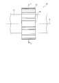
- FIG. 2 is a cross-sectional view taken along the line II-II in FIG.
- the paper sheet transporting roller 10 is a solid roller including a shaft 11 that is made of metal and forms the rotation axis X, and a roller body 13.
- the roller body 13 is formed in a substantially cylindrical shape, and is attached to the shaft 11 by inserting the shaft 11 through the hole 14 therein.
- the diameter of the hole 14 is the same as or smaller than the outer diameter of the shaft 11, the outer peripheral surface of the shaft 11 is in close contact with the inner peripheral surface of the roller body 13, and there is substantially no gap between them. .
- a plurality of teeth 16 arranged at equal intervals along the circumferential direction are formed on the outer circumferential surface of the roller body 13.
- the roller body 13 has an outer peripheral surface (particularly, teeth 16) that contacts the paper sheet and imparts a conveying force to the paper sheet.
- the roller main body 13 includes an inner layer 21 that forms the inner peripheral side of the roller main body 13, an outer layer 22 that forms the outer peripheral side of the roller main body 13, and a knitted fabric disposed between the inner layer 21 and the outer layer 22. (Knit) 20.
- the knitted fabric 20 is a knitted fabric having conductive yarns and is knitted seamlessly into a cylindrical shape, and constitutes a boundary surface between the inner layer 21 and the outer layer 22.
- the knitted fabric 20 is disposed concentrically with the roller body 13.
- the inner layer 21 and the outer layer 22 are made of a light-colored elastomer. That is, the roller body 13 is configured by embedding a conductive knitted fabric 20 in a light-colored elastomer so as not to be exposed on the outer peripheral surface of the roller body 13.
- the light-colored elastomer is not blended with a conductive material such as carbon black, which will be described later, or is blended only in a small amount, so that the lightness is 28 or more, preferably 38 or more, and its appearance is, for example, white or gray. If desired, pigments and the like are blended to make red, blue, yellow, green and the like. Further, the light color elastomer has a volume resistivity higher than that of the conductive knitted fabric 20, and may be substantially an insulator, for example. The lightness is measured, for example, using a color difference meter CR-200 (manufactured by Minolta).
- the elastomer component of the light-colored elastomer includes millable urethane, natural rubber (NR), styrene butadiene rubber (SBR), ethylene propylene diene rubber (EPDM), nitrile rubber (NBR), silicon rubber (VMQ), chloroprene rubber (CR), Chlorinated butyl rubber (Cl-IIR), chlorosulfonated polyethylene rubber (CSM), isoprene rubber (IR), butadiene rubber (BR), ethylene propylene rubber (EPM), butyl rubber (IIR), fluoro rubber (FKM), acrylic rubber A rubber such as (ACM) or a mixture thereof is used.
- the inner layer 21 and the outer layer 22 may be composed of elastomers having the same composition, but may have different compositions.
- the distance D1 between the knitted fabric 20 and the outer peripheral surface of the roller main body 13 is preferably shorter than the distance D2 between the knitted fabric 20 and the inner peripheral surface of the roller main body 13.
- the distance D1 is 4 mm or less, preferably 0.1 to 3 mm, in order to effectively prevent the outer peripheral surface of the roller body 13 from being charged.
- the knitted fabric 20 is composed of a plurality of loops juxtaposed in the axial direction and the circumferential direction of the roller body, for example, by knitting the yarn, and has high stretchability in any direction.
- the knitted fabric 20 is knitted by, for example, flat knitting, rubber knitting, loop knitting, or the like. At least a part of the yarn for knitting the knitted fabric 20 is preferably a yarn formed by winding a conductive yarn as a covering yarn around the outer periphery of the core yarn.
- the conductive yarn may be a composite of a resin fiber filament and carbon fiber, but a conductive yarn in which a conductive material such as carbon or copper sulfide is coated on the outer periphery of the resin fiber filament is preferable.
- the core yarn is a non-conductive yarn made of resin fiber or the like, but may be a conductive yarn as described above.
- a conductive yarn formed by coating a conductive material on the outer periphery of a filament is used, and the conductive material is wound around the outer periphery of the core yarn as a covering yarn, thereby exposing the conductive material to the surface of the knitted fabric 20. Therefore, the antistatic performance of the roller can be further improved.
- the knitted fabric 20 may be impregnated by dipping and drying in rubber paste formed by diluting rubber with a solvent.
- the knitted fabric 20 may be impregnated with a conductive rubber paste containing a conductive material.
- conductive materials include inorganic conductive powders such as carbon black, metals, and metal oxides, and inorganic conductive fibers such as carbon fibers, carbon nanotubes, and short metal oxide fibers such as lithium ions.
- An ionic conductive agent is used, and preferably carbon black is used.
- the conductivity of the knitted fabric 20 can be further improved.
- electroconductivity is provided to the knitted fabric 20 by rubber glue in this way, the knitted fabric 20 itself may have no conductive yarn and may be nonconductive.
- the rubber component of the rubber paste for example, chloroprene rubber is used.
- the roller body 13 in the present embodiment is vulcanized by, for example, press heating. Specifically, a first elastomer sheet for forming an inner layer around a mold core, a cylindrical knitted fabric impregnated if necessary, and a second elastomer sheet for forming an outer layer It winds in this order and press-molds from an outer peripheral side to radial direction. Note that a part of the elastomer of the first and second elastomer sheets (the inner layer 21 and the outer layer 22) may permeate into the inside of the knitted fabric (between the yarns knitting the knitted fabric) by press molding.
- the knitted fabric 20 is embedded in the roller main body, charging on the outer peripheral surface of the roller main body 13 can be sufficiently prevented, and multiple feeding and the like during paper feeding can be prevented. Moreover, since the knitted fabric 20 is not exposed to the outer peripheral surface of the roller main body 13, the physical property of a roller outer peripheral surface is not changed. Therefore, the roller body 13 can be provided with an antistatic function without reducing the wear resistance and friction coefficient of the roller outer peripheral surface.
- the elastomer constituting the roller body 13 does not contain a large amount of conductive material, and the roller body 13 is provided with the highly stretchable knitted fabric 20, the flexibility of the roller body 13 is enhanced, and the low load Since the conveyance is possible, it is possible to further improve the static electricity generation suppressing effect and the conveyance performance in the roller body 13.
- the roller body is made of a light-colored elastomer, it is possible to prevent color transfer from the outer peripheral surface of the roller to the paper sheet.
- the conductive cloth embedded in the roller body is a knitted cloth, but may be a woven cloth.
- the number of cloths embedded in the roller body may be two or more.
- Non-conductive core yarn made of polyethylene terephthalate fiber is wound around the outer circumference of a non-conductive core yarn covered with carbon (trade name “Metallian”, manufactured by Teijin) as a covering yarn.
- a knitted fabric was prepared. The knitted fabric was impregnated by dipping and drying in a rubber paste solution in which chloroprene rubber was dissolved in toluene. A first elastomer sheet, an impregnated knitted fabric, and a second elastomer were wound around the core in this order, and vulcanized by press heating from the outer peripheral side to obtain a roller body as shown in FIG. .
- the thickness D1 was 3 mm, D2 was 2.5 mm, and the thickness D3 of the entire roller body was 5.5 mm.
- natural rubber having a hardness after vulcanization of A30 was used as the first and second elastomer sheets.
- the hardness is a type A durometer hardness measured based on JIS K 6253.
- Example 2 Example except that the thicknesses of the first and second elastomer sheets were changed so that the thickness D1 was 4 mm, the thickness D2 was 1.5 mm, and the thickness D3 of the entire roller body was 5.5 mm. 1 was carried out.
- Example 1 A roller body having a thickness D3 of the entire roller body of 5.5 mm was molded without embedding a knitted fabric inside. The same rubber as in Example 1 was used as the rubber for the roller body.
- the roller main body obtained in each of the examples and comparative examples is inserted into a shaft and attached.
- the paper is fed by the roller main body, and the electrostatic potential after the paper feeding is measured by an electrostatic potential measuring device STATILON. -Measured by M2 (manufactured by Sisid Electric Co., Ltd.)
- the electrostatic potential measuring device was measured 2 mm away from the outer peripheral surface of the roller body radially outward.
- the paper feed was performed by A4 vertical feed with a load applied to the roller body during paper feed of 100 g, a paper feed number of 500 sheets, and a paper feed speed of 60 sheets / min. This test was conducted at an air temperature of 23 ° C. ⁇ 2 ° C. and a humidity of 50% ⁇ 10%.
- the electrostatic potential was measured twice, and the average value is shown in Table 1.
Landscapes
- Delivering By Means Of Belts And Rollers (AREA)
- Rolls And Other Rotary Bodies (AREA)
Abstract
紙葉類搬送用ローラ10は、内周側にシャフト11が挿通され、エラストマーから形成されるローラ本体13を備える。ローラ本体13の内部に、ローラ本体13の外周面に露出しないように、導電性を有する編布20が埋設される。編布20を編む糸の少なくとも一部は、樹脂繊維等から成る非導電糸を芯糸とし、その芯糸の外周に、導電糸をカバーリング糸として巻き回して形成された糸である。導電糸は、例えば導電材料がフィラメント外周に被覆されて成る糸である。
Description
本発明は、例えば、プリンター、複合機、コピー機、ファックス等の紙送りに使用され、帯電防止機能が付与された紙葉類搬送用ローラに関する。
従来、ゴムから形成されるローラ本体にシャフトを挿通させて構成されるソリッドローラが知られている。当該ローラは例えば、プリンター、複合機、コピー機、ファックス等において紙送り用途に使用され、ローラ外周面によって搬送力を与えて紙葉類を搬送する。このような紙葉類搬送用のソリッドローラは、静電気による紙の重送り等を防止するために、帯電防止を行う必要がある。
帯電防止の1つの方法としては、ローラ本体にカーボンブラック等の導電性粉体を配合してローラ本体自身に導電性を持たせることが考えられる。このとき、導電性粉体はローラ全体に均一に含有させられるのが一般的であるが、特許文献1のように、内周側のゴム層と外周側のゴム層に配合される導電性粉体の配合量を調整し、内周側の体積抵抗率を低くし、外周側の体積抵抗率を高くする場合がある。
特開平7-239600号公報
しかし、導電性粉体が配合されたローラは、その導電性粉体によって紙葉類が例えば黒色に汚染され、さらには、ローラの性能低下が引き起こされることがある。特に、ローラ表面の摩擦係数(すなわち、搬送力)や耐摩耗性の低下が引き起こされ、さらにはローラの柔軟性も損なわれることがある。ローラの柔軟性が低下すると、低荷重で紙葉類を搬送できなくなるため、紙葉類同士の擦れが大きくなり、静電気の発生を抑制する効果が低くなり、除電ブラシなどによる帯電防止が必要となる。また紙葉類を安定的に搬送させることが難しくなり、紙送り不良が生じやすくなる。
また、特許文献1に記載の導電性ローラでは、紙汚染やローラ表面の性能低下は軽減されるものの、内周側及び外周側のいずれのゴム層にも導電材料が配合されているため、ローラ表面の性能低下や紙汚染を十分に抑制できない。さらに、外周側に加えて内周側のゴム層に導電材料が配合されたことにより、ローラ全体としての硬度が高くなり、ローラの柔軟性が低下するおそれもある。
そこで、本発明は、以上の問題点に鑑みてなされたものであり、ローラ本体の性能を良好なものに維持しつつ、帯電防止性能を向上させることが可能な紙葉類搬送用ローラを提供することを目的とする。
本発明に係る紙葉類搬送用ローラは、内周側にシャフトが挿通され、エラストマーから形成されるローラ本体を備え、ローラ本体の内部に、ローラ本体の外周面に露出しないように、導電性を有する導電性布が埋設されることを特徴とする。
導電性布は、導電糸を含んでいても良いし、導電性布は、導電性を有するゴムに含浸されることにより導電性を有していても良い。また、導電性布は、芯糸の外周に導電糸をカバーリング糸として巻き回して形成された糸を含んでいても良い。導電糸は例えば、導電材料がフィラメント外周に被覆されて成る糸である。ローラ本体は、淡色エラストマーから形成されていたほうが良い。導電性布は、織布であっても良いが、編布であることが好ましい。また、導電性布は、ローラ本体内部に1枚埋設されていても良いが、2枚以上埋設されていても良い。
本発明においては、導電性を有する導電性布をローラ外周面に露出しないように設けたことにより、ローラ外周面の性能低下や紙葉類の汚染を引き起こすことなく、帯電防止性能に優れた紙葉類搬送用ローラを提供することができる。
10 紙葉類搬送用ローラ
11 シャフト
13 ローラ本体
16 歯
20 編布
21 内側層
22 外側層
11 シャフト
13 ローラ本体
16 歯
20 編布
21 内側層
22 外側層
以下、本発明の実施形態について図面を参照に説明する。図1、2は本発明の一実施形態に係る紙葉類搬送用ローラを示す。紙葉類搬送用ローラ10は、金属から形成され回転軸Xを構成するシャフト11と、ローラ本体13とを備えるソリッドローラである。ローラ本体13は、略円筒形状に形成されるものであって、その内部の孔14にシャフト11が挿通されてシャフト11に取り付けられるものである。孔14の径は、シャフト11の外径と同一であり又は外径より小さく、シャフト11の外周面はローラ本体13の内周面に密着し、これらの間には実質的に隙間が生じない。ローラ本体13の外周面には、周方向に沿って等間隔に並べられた複数の歯16が形成される。ローラ本体13は、その外周面(特に、歯16)が、紙葉類に接触し、紙葉類に対して搬送力を付与する。
ローラ本体13は、ローラ本体13の内周側を構成する内側層21と、ローラ本体13の外周側を構成する外側層22と、これら内側層21と外側層22の間に配置される編布(ニット)20とを備える。編布20は、導電糸を有する編布であって、シームレスに円筒形状に編まれたものであって、内側層21と、外側層22の境界面を構成する。編布20は、ローラ本体13と同心的に配置される。内側層21及び外側層22は、淡色エラストマーから構成される。すなわち、ローラ本体13は、淡色エラストマーの内部に、ローラ本体13の外周面に露出しないように、導電性を有する編布20が埋設されて構成される。
上記淡色エラストマーは、後述するカーボンブラック等の導電性材料が配合されないか、又は少量しか配合されないことにより、明度が28以上好ましくは38以上にされ、その外観が例えば白色、灰色にされ、また例えば所望により顔料等が配合されて赤色、青色、黄色、緑色等にされたものである。また、淡色エラストマーは、その体積抵抗率が、導電性を有する編布20よりも高く、例えば実質的に絶縁体であっても良い。なお、明度とは例えば、色彩色差計CR-200(ミノルタ社製)を用いて測定したものである。
淡色エラストマーのエラストマー成分としては、ミラブルウレタン、天然ゴム(NR)、スチレンブタジエンゴム(SBR)、エチレンプロピレンジエンゴム(EPDM)、ニトリルゴム(NBR)、シリコンゴム(VMQ)、クロロプレンゴム(CR)、塩素化ブチルゴム(Cl-IIR)、クロルスルフォン化ポリエチレンゴム(CSM)、イソプレンゴム(IR)、ブタジエンゴム(BR)、エチレンプロピレンゴム(EPM)、ブチルゴム(IIR)、フッ素ゴム(FKM)、アクリルゴム(ACM)、またはこれらの混合物等のゴムが使用される。内側層21、外側層22は、同一の組成を有するエラストマーから構成されても良いが、互いに異なる組成を有していても良い。
本実施形態では、編布20と、ローラ本体13の外周面(歯16の頂部)との距離D1は、編布20とローラ本体13の内周面との距離D2よりも短いほうが好ましい。これにより、編布20がローラ本体13の外周面近傍に配置されるため、ローラ本体13の外周面の帯電をより効果的に防止することができる。また、距離D1は、ローラ本体13の外周面の帯電を有効に防止するために、4mm以下、好ましくは0.1~3mmである。
編布20は、糸が編まれることにより、複数のループが、例えばローラ本体の軸方向及び周方向それぞれに複数並列されて成るものであり、いずれの方向にも高い伸縮性を有する。編布20は例えば平編み、ゴム編み、ループ編み等によって編まれたものである。編布20を編む糸の少なくとも一部は、芯糸の外周に、導電糸をカバーリング糸として巻き回して形成された糸であることが好ましい。その導電糸としては、樹脂繊維から成るフィラメントと炭素繊維とが複合されたものでも良いが、樹脂繊維から成るフィラメントの外周にカーボン、硫化銅等の導電材料が被覆された導電糸が好ましい。また、芯糸は、樹脂繊維等から成る非導電糸であるが、上記したような導電糸であっても良い。本実施形態では、導電材料がフィラメント外周に被覆されて成る導電糸を使用し、その導電糸を芯糸の外周にカバーリング糸として巻き回すことによって、編布20の表面に導電材料を露出させることができるので、ローラの帯電防止性能をより向上させることができる。編布20は、ゴムが溶剤に希釈されて形成されたゴム糊に浸漬・乾燥されることによって含浸処理が施されていても良い。
なお、編布20は、導電性材料が配合され、導電性を有するゴム糊によって含浸処理されても良い。導電性材料としては、例えば、カーボンブラック、金属、金属酸化物等の無機導電性粉体、カーボンファイバー、カーボンナノチューブ、金属酸化物短繊維等の無機導電性繊維、例えばリチウムイオンで導電性を付与するイオン導電剤が使用され、好ましくはカーボンブラックが使用される。ゴム糊に導電性材料が配合されることによって、編布20の導電性をより向上させることができる。なお、このように編布20がゴム糊によって導電性が付与される場合、編布20自身は導電糸を有しておらず非導電性であっても良い。ゴム糊のゴム成分としては、例えばクロロプレンゴムが使用される。
本実施形態におけるローラ本体13は、例えばプレス加熱によって加硫成型される。具体的には、金型の中芯の周りに内側層を構成するための第1エラストマーシート、所望により含浸処理をした円筒状の編布、及び外側層を構成するための第2エラストマーシートをこの順に巻き付けて、外周側から径方向にプレス成型する。なお、プレス成型により、第1及び第2エラストマーシート(内側層21、外側層22)のエラストマーの一部は、編布の内部(編布を編む糸同士の間)に浸透しても良い。
本実施形態では、編布20がローラ本体の内部に埋設されることにより、ローラ本体13の外周面における帯電を十分に防止でき、紙送り時の重送り等を防止することができる。また、編布20は、ローラ本体13の外周面に露出しないので、ローラ外周面の物性を変化させることがない。したがって、ローラ外周面の耐摩耗性や摩擦係数を低下させることなく、ローラ本体13に帯電防止機能を持たせることができる。さらに、ローラ本体13を構成するエラストマーに導電性材料が多量に含有されず、かつローラ本体13に伸縮性の高い編布20が設けられることにより、ローラ本体13の柔軟性が高められ、低荷重搬送が可能となるため、ローラ本体13における静電気発生の抑制効果や搬送性能をさらに向上させることも可能である。また、ローラ本体が淡色エラストマーから構成されるため、ローラ外周面から紙葉類への色写りを防止することが可能になる。
本実施形態では、ローラ本体の内部に埋設される導電性布は、編布であったが、織布であっても良い。ただし、ローラ本体の柔軟性を高めるためには、織布よりも編布を使用したほうが良い。また、ローラ本体の内部に埋設される布は、2枚以上であっても良い。
次に、本発明について実施例を用いてさらに詳細に説明するが、本発明は以下の実施例に限定されるものではない。
[実施例1]
ポリエチレンテレフタレート繊維から成る非導電性である芯糸の外周に、ナイロン繊維をカーボンで被覆した導電糸(商品名「メタリアン」、帝人製)をカバーリング糸として巻き回して形成した糸を平編みによって編んだ編布を用意した。編布には、クロロプレンゴムをトルエンに溶解させたゴム糊液に浸漬・乾燥させることによって含浸処理を施した。中芯の周りに第1のエラストマーシート、含浸処理を施した編布、第2のエラストマーをこの順に巻き付け、外周側からプレス加熱により加硫成型して図2に示すようなローラ本体を得た。ローラ本体において、厚さD1は、3mm、D2は2.5mm、ローラ本体全体の厚さD3が5.5mmであった。なお、第1及び第2のエラストマーシートとしては、加硫後の硬さがA30の天然ゴムを使用した。なお、硬さとは、JIS K 6253に基づいて測定されたタイプAデュロメータ硬さである。
ポリエチレンテレフタレート繊維から成る非導電性である芯糸の外周に、ナイロン繊維をカーボンで被覆した導電糸(商品名「メタリアン」、帝人製)をカバーリング糸として巻き回して形成した糸を平編みによって編んだ編布を用意した。編布には、クロロプレンゴムをトルエンに溶解させたゴム糊液に浸漬・乾燥させることによって含浸処理を施した。中芯の周りに第1のエラストマーシート、含浸処理を施した編布、第2のエラストマーをこの順に巻き付け、外周側からプレス加熱により加硫成型して図2に示すようなローラ本体を得た。ローラ本体において、厚さD1は、3mm、D2は2.5mm、ローラ本体全体の厚さD3が5.5mmであった。なお、第1及び第2のエラストマーシートとしては、加硫後の硬さがA30の天然ゴムを使用した。なお、硬さとは、JIS K 6253に基づいて測定されたタイプAデュロメータ硬さである。
[実施例2]
厚さD1が4mm、厚さD2が1.5mmとなり、ローラ本体全体の厚さD3が5.5mmとなるように、第1及び第2のエラストマーシートの厚さを変更した以外は、実施例1と同様に実施した。
厚さD1が4mm、厚さD2が1.5mmとなり、ローラ本体全体の厚さD3が5.5mmとなるように、第1及び第2のエラストマーシートの厚さを変更した以外は、実施例1と同様に実施した。
[比較例1]
内部に編布を埋設せずに、ローラ本体全体の厚さD3が5.5mmとなるローラ本体を成型した。ローラ本体のゴムは、実施例1と同様のゴムを使用した。
内部に編布を埋設せずに、ローラ本体全体の厚さD3が5.5mmとなるローラ本体を成型した。ローラ本体のゴムは、実施例1と同様のゴムを使用した。
各実施例、比較例で得られたローラ本体を、図1に示すようにシャフトに挿入して取り付け、ローラ本体で紙送りをして紙送り後の静電電位を、静電電位測定器スタチロン-M2(シシド静電気株式会社製)によって測定した。静電電位測定時には、静電電位測定器をローラ本体の外周面から径方向外側に2mm離して測定した。なお、紙送りは、紙送り時のローラ本体に作用される荷重を100g、給紙枚数500枚、紙送り速度60枚/分とし、A4タテ送りにより実施した。なお、当試験は気温23℃±2℃、湿度50%±10%で実施した。静電電位の測定は2回実施し、その平均値を表1に示す。

Claims (7)
- 内周側にシャフトが挿通され、エラストマーから形成されるローラ本体を備え、前記ローラ本体の内部に、ローラ本体の外周面に露出しないように、導電性を有する導電性布が埋設されることを特徴とする紙葉類搬送用ローラ。
- 前記導電性布は、導電糸を含むことを特徴とする請求項1に記載の紙葉類搬送用ローラ。
- 前記導電性布は、導電性を有するゴムに含浸されることにより導電性を有することを特徴とする請求項1に記載の紙葉類搬送用ローラ。
- 前記導電性布は、芯糸の外周に導電糸をカバーリング糸として巻き回して形成された糸を含むことを特徴とする請求項1に記載の紙葉類搬送用ローラ。
- 前記導電糸は、導電材料がフィラメント外周に被覆されたものであることを特徴とする請求項4に記載の紙葉類搬送用ローラ。
- 前記ローラ本体は、淡色エラストマーから形成されることを特徴とする請求項1ないし5のいずれか1項に記載の紙葉類搬送用ローラ。
- 前記導電性布は、編布又は織布であることを特徴とする請求項1ないし6のいずれか1項に記載の紙葉類搬送用ローラ。
Applications Claiming Priority (2)
| Application Number | Priority Date | Filing Date | Title |
|---|---|---|---|
| JP2009191016A JP2011042443A (ja) | 2009-08-20 | 2009-08-20 | 紙葉類搬送用ローラ |
| JP2009-191016 | 2009-08-20 |
Publications (1)
| Publication Number | Publication Date |
|---|---|
| WO2011021540A1 true WO2011021540A1 (ja) | 2011-02-24 |
Family
ID=43606995
Family Applications (1)
| Application Number | Title | Priority Date | Filing Date |
|---|---|---|---|
| PCT/JP2010/063545 Ceased WO2011021540A1 (ja) | 2009-08-20 | 2010-08-10 | 紙葉類搬送用ローラ |
Country Status (3)
| Country | Link |
|---|---|
| JP (1) | JP2011042443A (ja) |
| TW (1) | TW201111260A (ja) |
| WO (1) | WO2011021540A1 (ja) |
Families Citing this family (1)
| Publication number | Priority date | Publication date | Assignee | Title |
|---|---|---|---|---|
| JP7091750B2 (ja) | 2018-03-20 | 2022-06-28 | セイコーエプソン株式会社 | 媒体処理装置 |
Citations (6)
| Publication number | Priority date | Publication date | Assignee | Title |
|---|---|---|---|---|
| JPS53133056U (ja) * | 1977-03-30 | 1978-10-21 | ||
| JPS54552U (ja) * | 1977-06-04 | 1979-01-05 | ||
| JPS6112551A (ja) * | 1984-06-25 | 1986-01-20 | Nippon Seimitsu Kogyo Kk | 原稿搬送ベルト |
| JPH055750U (ja) * | 1991-07-05 | 1993-01-26 | 三ツ星ベルト株式会社 | 紙葉類搬送用平ゴムベルト |
| JPH10110787A (ja) * | 1996-10-08 | 1998-04-28 | Nitta Ind Corp | ベルト及びそのベルトの製造方法 |
| JP2008013874A (ja) * | 2006-07-05 | 2008-01-24 | Nippon Ester Co Ltd | 導電性複合糸及び導電性布帛 |
Family Cites Families (1)
| Publication number | Priority date | Publication date | Assignee | Title |
|---|---|---|---|---|
| JP2000025974A (ja) * | 1998-07-14 | 2000-01-25 | Bando Chem Ind Ltd | 原稿自動搬送装置用コンベヤベルト |
-
2009
- 2009-08-20 JP JP2009191016A patent/JP2011042443A/ja active Pending
-
2010
- 2010-08-10 WO PCT/JP2010/063545 patent/WO2011021540A1/ja not_active Ceased
- 2010-08-18 TW TW99127545A patent/TW201111260A/zh unknown
Patent Citations (6)
| Publication number | Priority date | Publication date | Assignee | Title |
|---|---|---|---|---|
| JPS53133056U (ja) * | 1977-03-30 | 1978-10-21 | ||
| JPS54552U (ja) * | 1977-06-04 | 1979-01-05 | ||
| JPS6112551A (ja) * | 1984-06-25 | 1986-01-20 | Nippon Seimitsu Kogyo Kk | 原稿搬送ベルト |
| JPH055750U (ja) * | 1991-07-05 | 1993-01-26 | 三ツ星ベルト株式会社 | 紙葉類搬送用平ゴムベルト |
| JPH10110787A (ja) * | 1996-10-08 | 1998-04-28 | Nitta Ind Corp | ベルト及びそのベルトの製造方法 |
| JP2008013874A (ja) * | 2006-07-05 | 2008-01-24 | Nippon Ester Co Ltd | 導電性複合糸及び導電性布帛 |
Also Published As
| Publication number | Publication date |
|---|---|
| JP2011042443A (ja) | 2011-03-03 |
| TW201111260A (en) | 2011-04-01 |
Similar Documents
| Publication | Publication Date | Title |
|---|---|---|
| KR101533751B1 (ko) | 화상 형성 장치용 청소 부재, 대전 장치, 화상 형성 장치용 유닛, 프로세스 카트리지, 및 화상 형성 장치 | |
| US20110250439A1 (en) | Intermediate trasnfer member comprising a toughened fluoroplastic composite surface layer | |
| WO2011021540A1 (ja) | 紙葉類搬送用ローラ | |
| US20200055683A1 (en) | Paper feed roller | |
| JP2020101639A (ja) | 中間転写ベルト及び画像形成装置 | |
| JP5137223B2 (ja) | 紙葉類搬送用ローラ | |
| WO2011021542A1 (ja) | 紙葉類搬送用ローラ | |
| CN105683069B (zh) | 送纸辊 | |
| US11474444B2 (en) | Intermediate transfer belt and image forming apparatus | |
| US8971781B2 (en) | Roller for image-forming apparatus and process for producing the same | |
| JP2016038010A (ja) | 無端ベルト | |
| JP4923525B2 (ja) | 半導電性ベルトおよび画像形成装置 | |
| JP3820764B2 (ja) | 転写ベルト部材 | |
| JP3759115B2 (ja) | 導電性中間転写ゴムベルト | |
| US8401451B2 (en) | Heating fixing roller and process for producing the heating fixing roller | |
| EP2297614B1 (en) | Endless belt for use in digital imaging systems | |
| JP3821600B2 (ja) | シームレスベルト | |
| JP2011095480A (ja) | 導電性シームレスベルト | |
| JP4451677B2 (ja) | 表面保護層付きシームレスベルト及びその製造方法 | |
| JP3409280B2 (ja) | 導電性ベルト | |
| JP4813858B2 (ja) | 転写ローラ、その製造方法および画像形成装置 | |
| JPH09114197A (ja) | 導電性ロール | |
| JP7175742B2 (ja) | 中間転写ベルト及び画像形成装置 | |
| JP2012088677A (ja) | 電子写真機器用帯電ロール | |
| JP3970002B2 (ja) | フッ素系シームレス機能ベルト |
Legal Events
| Date | Code | Title | Description |
|---|---|---|---|
| 121 | Ep: the epo has been informed by wipo that ep was designated in this application |
Ref document number: 10809885 Country of ref document: EP Kind code of ref document: A1 |
|
| NENP | Non-entry into the national phase |
Ref country code: DE |
|
| 122 | Ep: pct application non-entry in european phase |
Ref document number: 10809885 Country of ref document: EP Kind code of ref document: A1 |