WO2011016294A1 - マグネット錠 - Google Patents
マグネット錠 Download PDFInfo
- Publication number
- WO2011016294A1 WO2011016294A1 PCT/JP2010/060518 JP2010060518W WO2011016294A1 WO 2011016294 A1 WO2011016294 A1 WO 2011016294A1 JP 2010060518 W JP2010060518 W JP 2010060518W WO 2011016294 A1 WO2011016294 A1 WO 2011016294A1
- Authority
- WO
- WIPO (PCT)
- Prior art keywords
- magnet
- rotor
- key
- support protrusion
- lock
- Prior art date
Links
Images


Classifications
-
- E—FIXED CONSTRUCTIONS
- E05—LOCKS; KEYS; WINDOW OR DOOR FITTINGS; SAFES
- E05B—LOCKS; ACCESSORIES THEREFOR; HANDCUFFS
- E05B17/00—Accessories in connection with locks
- E05B17/14—Closures or guards for keyholes
- E05B17/142—Closures or guards for keyholes with key-operated locks, e.g. padlocks
-
- E—FIXED CONSTRUCTIONS
- E05—LOCKS; KEYS; WINDOW OR DOOR FITTINGS; SAFES
- E05B—LOCKS; ACCESSORIES THEREFOR; HANDCUFFS
- E05B47/00—Operating or controlling locks or other fastening devices by electric or magnetic means
- E05B47/0038—Operating or controlling locks or other fastening devices by electric or magnetic means using permanent magnets
- E05B47/0045—Operating or controlling locks or other fastening devices by electric or magnetic means using permanent magnets keys with permanent magnets
Definitions
- a fixed casing is provided with a rotor formed of a nonmagnetic material having a fitting recess into which a magnetic key can be removably fitted and a wall portion serving as a closed end of the fitting recess.
- a plurality of support protrusions rotatably supported so that the wall portion faces the tip of the support protrusion, and are provided at the tip of the support protrusion and open to the wall portion side.
- a rod-shaped first permanent magnet that can be engaged with the wall portion is inserted into a specific sliding recess selected from among the sliding recesses, and protrudes from the tip of the support protrusion to spring on the side that engages with the wall portion.
- a plurality of the magnet keys are slidably fitted while being energized, and the wall is interposed between the magnet key and the first permanent magnet when the magnet key is fitted into the fitting recess.
- the present invention relates to a magnetic lock in which a single bar-shaped second permanent magnet is accommodated and fixed.
- a plurality of permanent magnets having a circular cross-sectional shape that are magnetized so that the direction of magnetic force is in the direction along the axis of the rotor are formed on the support protrusions of the casing.
- a specific sliding recess selected from among the plurality of sliding recesses provided is slidably fitted to enable engagement with the rotor, and individually corresponds to the plurality of first permanent magnets.
- the magnet lock is unlocked when the magnetic pole on the rotor side of the plurality of second permanent magnets arranged on the magnet key side is the same as the magnetic pole on the magnet key side of the corresponding first permanent magnet. ing.
- the N pole of the first permanent magnet is disposed on the magnet key side and the S pole of the first permanent magnet is disposed on the magnet key side with respect to one sliding recess.
- Only two types can change the type of magnet key, and in order to increase the type of magnet key, it is necessary to increase the number of sliding recesses and the number of first permanent magnets fitted in the sliding recesses. This leads to an increase in size and cost.
- the present invention has been made in view of such circumstances, and an object thereof is to provide a magnetic lock capable of increasing the types of magnetic keys while avoiding an increase in size and cost.
- the present invention is formed of a nonmagnetic material having a fitting recess into which a magnet key can be removably fitted and a wall portion serving as a closed end of the fitting recess.
- a rotor is rotatably supported on a support projection provided on a fixed casing so that the wall portion faces the tip of the support projection, and the rotor is provided on the tip of the support projection.
- a rod-shaped first permanent magnet that can be engaged with the wall portion protrudes from the tip of the support protrusion into a specific sliding recess selected from among a plurality of sliding recesses that open to the side of the wall.
- the wall is interposed between the magnet key and the first permanent magnet when the magnet key is fitted into the fitting recess.
- a plurality of rod-shaped second permanent magnets are accommodated and fixed so as to interpose the part.
- the first and second permanent magnets formed so as to have a square cross-sectional shape are magnetized so that the direction of the magnetic force is in a direction along a plane perpendicular to the rotation axis of the rotor. Is the first feature.
- the support protrusion is provided in the casing fixedly arranged so as to cover a front end portion of a cylinder body included in the cylinder lock, and the key hole of the cylinder lock is provided in the keyhole.
- a second feature is that a shutter plate that opens and closes in conjunction with rotation of the rotor is housed in the casing.
- the first and second permanent magnets having a square cross-sectional shape are magnetized so that the direction of the magnetic force is in a direction along a plane perpendicular to the rotation axis of the rotor. Therefore, by changing the assembly direction of the first permanent magnet to the sliding recess provided on the support protrusion by 90 degrees, four types of magnet keys can be changed for one sliding recess. Compared to the conventional one that can only be changed, the number of types of magnet keys can be increased without increasing the number of sliding recesses and first permanent magnets, thereby avoiding an increase in size and cost. However, the types of magnet keys can be increased.
- the second feature of the present invention it is possible to increase the types of magnet keys used in the protection device in which the key hole of the cylinder lock is closed with the shutter plate.
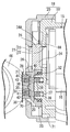
- FIG. 1 is a longitudinal side view of the cylinder lock protection device in a state before the shutter key is in the closed position and the magnet key is fitted, and is a cross-sectional view taken along line 1-1 of FIG.
- FIG. 2 is a longitudinal side view of the cylinder lock protection device in a state where the shutter plate is in the closed position and the magnet key is fitted.
- FIG. 3 is a view taken along line 3-3 in FIG.
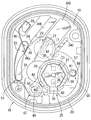
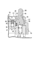
- First embodiment 4 is a cross-sectional view taken along line 4-4 of FIG.
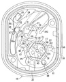
- First embodiment 5 is a cross-sectional view taken along line 5-5 of FIG.
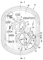
- FIG. 6 is a cross-sectional view corresponding to FIG. 4 with the shutter plate rotated to the open position.
- FIG. 1 is a longitudinal side view of the cylinder lock protection device in a state before the shutter key is in the closed position and the magnet key is fitted, and is a cross-sectional view taken along line 1-1 of FIG.
- FIG. 2 is a longitudinal side view of the cylinder lock protection device in
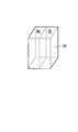
- FIG. 7 is a perspective view of the first permanent magnet.
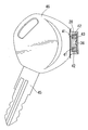
- FIG. 8 is a partially cutaway side view for showing a magnet key attached to the mechanical key.
- (First embodiment) 9 is a cross-sectional view taken along line 9-9 of FIG. (First embodiment)
- a cylinder body 16 of a cylinder lock 15 for a vehicle such as a motorcycle is provided on a head pipe (not shown) of a vehicle body frame. It is covered with a casing 18 fixed to the side.
- the casing 18 includes a case member 19 made of a nonmagnetic material attached to the front end of the cylinder body 16 and a cover member 20 made of a nonmagnetic material attached to the case member 19.
- the casing 18 is provided with an insertion hole 21 corresponding to the key hole 17 disposed at the center of the front end of the cylinder lock 15.
- the insertion hole 21 is composed of through holes 22 and 23 provided coaxially in the case member 19 and the cover member 20, respectively.
- the outer end portion of the through hole 23 is inserted with a mechanical key 45 (see FIG. 8). In order to facilitate, it is formed in a tapered shape.
- the casing 18 has a closed position (position shown in FIGS. 4 and 5) for closing the key hole 17 and the insertion hole 21, and the key hole 17 and the A shutter plate 24 that can be slid between the open position for opening the insertion hole 21 (the position shown in FIG. 6) is housed.
- the sliding operation of the shutter plate 24 is allowed by fitting a magnet key 28 as shown in FIG. 2 into a fitting recess 27 provided in the magnet lock 25 disposed in the casing 18.
- the lock 25 includes a rotor 26 that is rotatably supported by the casing 18, and the fitting recess 27 is provided in the rotor 26.
- the case member 19 of the casing 18 is integrally provided with a support protrusion 29 having a circular cross section projecting toward the cover member 20, and the cover member 20 has a circular shape corresponding to the support protrusion 29.
- An opening 30 is provided.
- the rotor 26 has a wall portion 31 serving as a closed end portion of the fitting concave portion 27 at an intermediate portion in the axial direction, and is formed in a substantially cylindrical shape by a nonmagnetic material.
- the O-ring 32 is interposed between the base of the support protrusion 29 and the rotor 26, and the outer end of the rotor 26 faces the opening 30.
- the shutter plate 24 is sandwiched between the case member 19 and the cover member 20 of the casing 18 so as to be slidable between the closed position shown in FIGS. 4 and 5 and the open position shown in FIG.
- a plurality of, for example, three protrusions 34 A, 34 B, and 34 C are provided on the shutter plate 24 in order to avoid an increase in frictional resistance caused by the entire surface of the shutter plate 24 being in sliding contact with the case member 19. It protrudes so as to be in sliding contact.
- the fitting recess 27 of the rotor 26 is formed to have, for example, an irregular octagonal cross-sectional shape, and a protrusion 35 is provided in a projecting manner at a substantially central portion of the fitting recess 27.
- the magnet key 28 having a cross-sectional shape corresponding to the cross-sectional shape of the fitting recess 27 and having the recess 36 into which the protrusion 35 is fitted can be fitted into the fitting recess 27.
- the lower portion of the rotor 26 is cut out so as to form a discharge groove 70 for discharging water that has entered the fitting recess 27, and a discharge passage 71 that leads to the discharge groove 70 serves as a case member 19 and a cover member 20.
- the lower end of the discharge passage 71 is opened to the outside at the lower portion of the casing 18.
- a plurality of, for example, four sliding recesses 37 corresponding to square corners, for example, are provided at the tip of the support protrusion 29 so as to open to the rotor 26 side. 37.
- the selected sliding recesses 37 of the rods 37 are slidably fitted with rod-shaped first permanent magnets 38, respectively, between the bottoms of the sliding recesses 37 and the first permanent magnets 38.
- the first permanent magnet 38 is formed in a rod shape having a square cross-sectional shape, and is magnetized so that the magnetic force direction is along a plane perpendicular to the rotation axis of the rotor 26. That is, the first permanent magnet 38 is magnetized so that one half of the cross-sectional shape is an N pole and the remaining half is an S pole.
- the sliding recesses 37 are also formed to have a square cross-sectional shape so that the first permanent magnets 38 can be slidably fitted. For example, a pair of parallel two sides extends in the radial direction of the rotor 26. The sliding recesses 37 are provided in the rotor 26 along the same direction. Thus, the first permanent magnets 38... Are selected from the sliding recesses 37 so that the magnetic pole arrangement in the plane perpendicular to the rotation axis of the rotor 26 is an appropriate combination. It is slidably fitted to....
- the first permanent magnet 38 has a state in which the N pole is on the radially inner side of the rotor 26 and the S pole is on the radially outer side of the rotor 26, and the N pole is on the radially outer side of the rotor 26.
- the S pole is on the radially inner side of the rotor 26 and the N pole is on one circumferential side of the rotor 26 and the S pole is on the other circumferential side of the rotor 26.
- the selected sliding recess 37 It is slidably fitted.
- engagement recesses 40 for engaging a part of the first permanent magnets 38 are provided in a square cross section corresponding to the sliding recesses 37.
- the magnet key 28 is attached to the knob 46 of the mechanical key 45 for the cylinder lock 15 and has an outer peripheral shape corresponding to the inner peripheral shape of the fitting recess 27 in the rotor 26. It is formed.
- the magnet key 28 has a plurality of, for example, four receiving recesses 41 arranged at positions corresponding to the arrangement of the first permanent magnets 38 arranged on the support protrusion 29.
- the second permanent magnets 42 are housed in the housing recesses 41 selected from among the housing recesses 41. Moreover, the open end of each accommodation recessed part 41 ... is closed with the obstruction
- the key 28 is housed and fixed.
- the second permanent magnets 42 are formed in a bar shape having a square cross section, like the first permanent magnets 38, so that the direction of the magnetic force is along a plane perpendicular to the rotational axis of the rotor 26. Is magnetized.
- the magnetic pole arrangement in the plane of the second permanent magnets 42 arranged on the magnet key 28 is the same as the magnetic pole arrangement in the plane of the first permanent magnets 38 on the support protrusion 29 side.
- the shutter plate 24 housed in the casing 18 opens and closes the key hole 17 in conjunction with the rotation of the rotor 26.
- the rotor 26 is connected via a link mechanism 47.
- the link mechanism 47 has a connecting arm 48 integrally provided on the outer periphery of the rotor 26 so as to extend to one end side of the shutter plate 24, and a connecting arm having an axis parallel to the rotation axis of the rotor 26.
- the shutter plate 24 is in a closed position for closing the insertion hole 21 of the casing 18 to protect the cylinder lock 15 (the state shown in FIGS. 1 to 5), and as shown in FIG.
- the open position where the cylinder lock 15 is open and allows the key to be inserted into the key hole 17 of the cylinder lock 15.
- each first permanent of the support protrusion 29 is allowed to slide.
- the magnets 38 can be engaged with the engagement recesses 40 of the rotor 26, and the first permanent magnets 38 of the support projection 29 are engaged with the engagement recesses 40 of the rotor 26 in the open position.
- the rotation range of the rotor 26 is determined so as to correspond to the slide operation range between the closed position and the open position of the shutter plate 24 so that they cannot be combined.
- guide means 51 for guiding the sliding operation of the shutter plate 24 between the closed position and the open position is provided.
- the guide means 51 is provided on the case member 19.
- the guide pin 52 is provided and a guide hole 53 provided in the shutter plate 24 so that the guide pin 52 is slidably fitted.
- the shutter plate 24 slides so as to be guided by the guide pin 52 fitted in the guide hole 53.
- a click mechanism 56 is provided between the case member 19 of the casing 18 and the rotor 26 to determine the rotation limit of the rotor 26 corresponding to the closed position and the open position of the shutter plate 24.
- the click mechanism 56 has a bottomed storage hole 58 provided in the case member 19 so as to open opposite to the flange 57 provided at one end on the outer periphery of the rotor 26 on the side opposite to the connection arm 48.
- An engagement groove 61 provided in the flange portion 57 so as to engage the ball 59 when the plate 24 is in the closed position, and the ball 59 is engaged when the shutter plate 24 is in the open position.
- a engaging groove 62 provided in the flange portion 57 in the so that.
- An open position holding mechanism 64 is provided between the case member 19 of the casing 18 and the shutter plate 24 to elastically hold the shutter plate 24 in the open position.
- One end is attached to the protrusion 65 projecting from the case member 19 and the leaf spring 66 provided with an arcuate engagement portion 66a at the other end is engaged with the engagement portion 66a in the open position. And is configured to be engaged with the engaging portion 67 when the shutter plate 24 is in the open position, as shown in FIG.
- the portion 66a can be elastically engaged to hold the shutter plate 24 in the open position.
- the elastic force of the engaging portion 66a to the locking portion 67 is applied.
- the leaf spring 66 can be bent so as to release the firing engagement, whereby the shutter plate 24 can be rotated to the closed position side.
- the flange portion 57 of the rotor 26 is provided with a pin-shaped operation knob 68 protruding to the opposite side of the case member 19, and a through hole 69 through which the operation knob 68 passes is connected to, for example, the opening 30.
- the cover member 20 of the casing 18 is provided.
- the through hole 69 is formed so as to allow the operation knob 68 to move with the slide operation between the closed position and the open position of the shutter plate 24.
- Specific sliding recesses 37 selected from among a plurality of sliding recesses 37 provided at the tip of a fixed support projection 29 provided in the casing 18.
- a rod-shaped first permanent magnet 38 Provided on the rotor 26 rotatably supported by the support protrusion 29 and engageable with a wall 31 facing the tip of the support protrusion 29 is formed on the wall.
- Each of the first permanent magnets is slidably fitted while being urged by a spring on the side engaging with the portion 31, and the magnet key 28 is fitted to the fitting recess 27 of the rotor 26.
- a plurality of rod-shaped second permanent magnets 42 are accommodated and fixed so that the wall portion 31 is interposed between the first and second permanent magnets 38. , Formed so that the cross-sectional shape is square And it is magnetized so as to face the magnetic force in the direction along a plane perpendicular to the rotation axis of the rotor 26.
- the type of the magnet key 28 is changed with respect to one sliding recess 37.
- the number of types of magnet keys 28 can be increased without increasing the number of sliding recesses 37...
- the number of types of magnet keys 28 can be increased while avoiding an increase in size and cost.
- the support protrusion 29 is provided in the casing 18 that covers the front end of the cylinder body 16 provided in the cylinder lock 15 and is fixed to the vehicle body frame.
- the key hole 17 of the cylinder lock 15 is interlocked with the rotation of the rotor 26. Since the shutter plate 24 that opens and closes is housed in the casing 18, the number of types of magnet keys 28 used in the protection device in which the key hole 17 of the cylinder lock 15 is closed by the shutter plate 24 may be increased. it can.
- the shutter plate 24 is connected to the rotor 26 via the link mechanism 47, but the rotor and the shutter plate may be integrally formed.
Landscapes
- Lock And Its Accessories (AREA)
Abstract
Description
16・・・シリンダボディ
17・・・キー孔
18・・・ケーシング
24・・・シャッター板
26・・・ロータ
27・・・嵌合凹部
28・・・マグネットキー
29・・・支持突部
31・・・壁部
37・・・摺動凹部
38・・・第1永久磁石
42・・・第2永久磁石
Claims (2)
- マグネットキー(28)を挿脱可能に嵌合し得る嵌合凹部(27)ならびに該嵌合凹部(27)の閉塞端部となる壁部(31)を有して非磁性材料で形成されるロータ(26)が、固定のケーシング(18)に設けられた支持突部(29)に、該支持突部(29)の先端に前記壁部(31)を対向させるようにして回動可能に支承され、前記支持突部(29)の先端に設けられて前記壁部(31)側に開口する複数個の摺動凹部(37)のうち選択された特定の摺動凹部(37)に、前記壁部(31)に係合可能な棒状の第1永久磁石(38)が、前記支持突部(29)の先端から突出して前記壁部(31)に係合する側にばね付勢されつつそれぞれ摺動可能に嵌合され、前記マグネットキー(28)に、前記嵌合凹部(27)への該マグネットキー(28)の嵌合時に前記第1永久磁石(38)との間に前記壁部(31)を介在させるようにして複数個の棒状の第2永久磁石(42)が収容、固定されるマグネット錠において、横断面形状が正方形となるように形成される第1および第2永久磁石(38,42)が、前記ロータ(26)の回動軸線に直交する平面に沿う方向に磁力方向が向くように着磁されることを特徴とするマグネット錠。
- シリンダ錠(15)が備えるシリンダボディ(16)の前端部を覆って固定配置される前記ケーシング(18)に前記支持突部(29)が設けられ、前記シリンダ錠(15)のキー孔(17)を前記ロータ(26)の回動に連動して開閉するシャッター板(24)が、前記ケーシング(18)内に収納されることを特徴とする請求項1記載のマグネット錠。
Priority Applications (2)
| Application Number | Priority Date | Filing Date | Title |
|---|---|---|---|
| CN201080034610.3A CN102472054B (zh) | 2009-08-05 | 2010-06-22 | 磁性锁 |
| BR112012002438A BR112012002438A2 (pt) | 2009-08-05 | 2010-06-22 | trava magnética |
Applications Claiming Priority (2)
| Application Number | Priority Date | Filing Date | Title |
|---|---|---|---|
| JP2009-182443 | 2009-08-05 | ||
| JP2009182443A JP5162537B2 (ja) | 2009-08-05 | 2009-08-05 | マグネット錠 |
Publications (1)
| Publication Number | Publication Date |
|---|---|
| WO2011016294A1 true WO2011016294A1 (ja) | 2011-02-10 |
Family
ID=43544196
Family Applications (1)
| Application Number | Title | Priority Date | Filing Date |
|---|---|---|---|
| PCT/JP2010/060518 WO2011016294A1 (ja) | 2009-08-05 | 2010-06-22 | マグネット錠 |
Country Status (5)
| Country | Link |
|---|---|
| JP (1) | JP5162537B2 (ja) |
| CN (1) | CN102472054B (ja) |
| BR (1) | BR112012002438A2 (ja) |
| TW (1) | TWI448611B (ja) |
| WO (1) | WO2011016294A1 (ja) |
Cited By (1)
| Publication number | Priority date | Publication date | Assignee | Title |
|---|---|---|---|---|
| CN106593102A (zh) * | 2017-01-25 | 2017-04-26 | 栗新 | 一种磁编码电子钥匙解闭锁装置的磁控结构及工作方法 |
Families Citing this family (1)
| Publication number | Priority date | Publication date | Assignee | Title |
|---|---|---|---|---|
| JP6061093B2 (ja) * | 2013-09-11 | 2017-01-18 | 株式会社ホンダロック | シリンダ錠の保護装置 |
Citations (2)
| Publication number | Priority date | Publication date | Assignee | Title |
|---|---|---|---|---|
| JP2006144288A (ja) * | 2004-11-17 | 2006-06-08 | Honda Motor Co Ltd | 車両用シリンダ錠の保護装置 |
| JP2009127406A (ja) * | 2007-11-28 | 2009-06-11 | Honda Lock Mfg Co Ltd | マグネット錠 |
Family Cites Families (7)
| Publication number | Priority date | Publication date | Assignee | Title |
|---|---|---|---|---|
| JP3821427B2 (ja) * | 2001-04-26 | 2006-09-13 | 朝日電装株式会社 | シリンダ錠の保護装置 |
| JP3914043B2 (ja) * | 2001-09-14 | 2007-05-16 | 株式会社ホンダロック | 車両用シリンダ錠の保護装置 |
| JP3770319B2 (ja) * | 2002-05-07 | 2006-04-26 | 朝日電装株式会社 | 車両用シリンダ錠の保護装置 |
| JP4333983B2 (ja) * | 2003-08-28 | 2009-09-16 | 朝日電装株式会社 | シリンダ錠の保護装置 |
| TWM247647U (en) * | 2003-12-10 | 2004-10-21 | Yung-Ru Huang | Escutcheon used in motorcycle cylinder lock |
| TWI232823B (en) * | 2003-12-10 | 2005-05-21 | Yung-Ru Huang | Lock cover for motorcycle |
| ES1063479Y (es) * | 2006-07-03 | 2007-05-16 | Accesorios Y Resortes S L | Picaporte perfeccionado para puertas |
-
2009
- 2009-08-05 JP JP2009182443A patent/JP5162537B2/ja not_active Expired - Fee Related
-
2010
- 2010-06-22 CN CN201080034610.3A patent/CN102472054B/zh not_active Expired - Fee Related
- 2010-06-22 WO PCT/JP2010/060518 patent/WO2011016294A1/ja active Application Filing
- 2010-06-22 BR BR112012002438A patent/BR112012002438A2/pt not_active IP Right Cessation
- 2010-06-25 TW TW99120797A patent/TWI448611B/zh not_active IP Right Cessation
Patent Citations (2)
| Publication number | Priority date | Publication date | Assignee | Title |
|---|---|---|---|---|
| JP2006144288A (ja) * | 2004-11-17 | 2006-06-08 | Honda Motor Co Ltd | 車両用シリンダ錠の保護装置 |
| JP2009127406A (ja) * | 2007-11-28 | 2009-06-11 | Honda Lock Mfg Co Ltd | マグネット錠 |
Cited By (1)
| Publication number | Priority date | Publication date | Assignee | Title |
|---|---|---|---|---|
| CN106593102A (zh) * | 2017-01-25 | 2017-04-26 | 栗新 | 一种磁编码电子钥匙解闭锁装置的磁控结构及工作方法 |
Also Published As
| Publication number | Publication date |
|---|---|
| BR112012002438A2 (pt) | 2016-03-01 |
| TW201116693A (en) | 2011-05-16 |
| TWI448611B (zh) | 2014-08-11 |
| JP2011032816A (ja) | 2011-02-17 |
| CN102472054A (zh) | 2012-05-23 |
| CN102472054B (zh) | 2014-06-25 |
| JP5162537B2 (ja) | 2013-03-13 |
Similar Documents
| Publication | Publication Date | Title |
|---|---|---|
| JP3914043B2 (ja) | 車両用シリンダ錠の保護装置 | |
| TWI384109B (zh) | 圓筒鎖保護裝置(三) | |
| JP5189346B2 (ja) | マグネット錠 | |
| TWI398572B (zh) | 用於車輛鎖住裝置之保護裝置以及具有該保護裝置之車輛鎖住機構與鞍形車輛 | |
| JP4958810B2 (ja) | 車両用シリンダ錠装置 | |
| WO2011016294A1 (ja) | マグネット錠 | |
| JP4856434B2 (ja) | シリンダ錠の保護装置 | |
| JP4530589B2 (ja) | 車両用シリンダ錠の保護装置 | |
| EP3988747B1 (en) | Case for electronic padlock with knob | |
| JP4954168B2 (ja) | シリンダ錠の保護装置 | |
| JP6061093B2 (ja) | シリンダ錠の保護装置 | |
| JP6187908B2 (ja) | シリンダ錠の保護装置 | |
| JP4554338B2 (ja) | 車両用シリンダ錠の保護装置 | |
| JP6348824B2 (ja) | シリンダ錠用保護装置 | |
| JP4939378B2 (ja) | シリンダ錠の保護装置 | |
| WO2016072267A1 (ja) | 開閉装置用開き作動規制装置 | |
| JP5112254B2 (ja) | シリンダ錠の保護装置 | |
| JP2009138465A (ja) | マグネット錠 | |
| JP4478828B2 (ja) | ワイヤー錠 | |
| JP6284416B2 (ja) | シリンダ錠の保護装置 | |
| JP6150342B2 (ja) | シリンダ錠の保護装置 | |
| JP5924777B2 (ja) | シリンダ錠の保護装置 | |
| JP2016089336A5 (ja) | ||
| JP2016089336A (ja) | キーユニット |
Legal Events
| Date | Code | Title | Description |
|---|---|---|---|
| WWE | Wipo information: entry into national phase |
Ref document number: 201080034610.3 Country of ref document: CN |
|
| 121 | Ep: the epo has been informed by wipo that ep was designated in this application |
Ref document number: 10806294 Country of ref document: EP Kind code of ref document: A1 |
|
| WWE | Wipo information: entry into national phase |
Ref document number: 1201000395 Country of ref document: TH |
|
| NENP | Non-entry into the national phase |
Ref country code: DE |
|
| 122 | Ep: pct application non-entry in european phase |
Ref document number: 10806294 Country of ref document: EP Kind code of ref document: A1 |
|
| REG | Reference to national code |
Ref country code: BR Ref legal event code: B01A Ref document number: 112012002438 Country of ref document: BR |
|
| ENP | Entry into the national phase |
Ref document number: 112012002438 Country of ref document: BR Kind code of ref document: A2 Effective date: 20120202 |