WO2011001472A1 - 移載装置 - Google Patents
移載装置 Download PDFInfo
- Publication number
- WO2011001472A1 WO2011001472A1 PCT/JP2009/003071 JP2009003071W WO2011001472A1 WO 2011001472 A1 WO2011001472 A1 WO 2011001472A1 JP 2009003071 W JP2009003071 W JP 2009003071W WO 2011001472 A1 WO2011001472 A1 WO 2011001472A1
- Authority
- WO
- WIPO (PCT)
- Prior art keywords
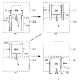
- load
- arm
- contact
- contact body
- luggage
- Prior art date
- Legal status (The legal status is an assumption and is not a legal conclusion. Google has not performed a legal analysis and makes no representation as to the accuracy of the status listed.)
- Ceased
Links
Images


Classifications
-
- B—PERFORMING OPERATIONS; TRANSPORTING
- B65—CONVEYING; PACKING; STORING; HANDLING THIN OR FILAMENTARY MATERIAL
- B65G—TRANSPORT OR STORAGE DEVICES, e.g. CONVEYORS FOR LOADING OR TIPPING, SHOP CONVEYOR SYSTEMS OR PNEUMATIC TUBE CONVEYORS
- B65G1/00—Storing articles, individually or in orderly arrangement, in warehouses or magazines
- B65G1/02—Storage devices
- B65G1/04—Storage devices mechanical
- B65G1/0407—Storage devices mechanical using stacker cranes
- B65G1/0435—Storage devices mechanical using stacker cranes with pulling or pushing means on either stacking crane or stacking area
-
- B—PERFORMING OPERATIONS; TRANSPORTING
- B66—HOISTING; LIFTING; HAULING
- B66F—HOISTING, LIFTING, HAULING OR PUSHING, NOT OTHERWISE PROVIDED FOR, e.g. DEVICES WHICH APPLY A LIFTING OR PUSHING FORCE DIRECTLY TO THE SURFACE OF A LOAD
- B66F9/00—Devices for lifting or lowering bulky or heavy goods for loading or unloading purposes
- B66F9/06—Devices for lifting or lowering bulky or heavy goods for loading or unloading purposes movable, with their loads, on wheels or the like, e.g. fork-lift trucks
- B66F9/07—Floor-to-roof stacking devices, e.g. "stacker cranes", "retrievers"
-
- B—PERFORMING OPERATIONS; TRANSPORTING
- B65—CONVEYING; PACKING; STORING; HANDLING THIN OR FILAMENTARY MATERIAL
- B65G—TRANSPORT OR STORAGE DEVICES, e.g. CONVEYORS FOR LOADING OR TIPPING, SHOP CONVEYOR SYSTEMS OR PNEUMATIC TUBE CONVEYORS
- B65G1/00—Storing articles, individually or in orderly arrangement, in warehouses or magazines
- B65G1/02—Storage devices
- B65G1/04—Storage devices mechanical
Definitions
- the present invention relates to a transfer device that slides and transfers a load from a first placement location to a second placement location, such as a stacker crane or a station of an unmanned conveyance system.
- the stacker crane In order to transfer a load between a rack that holds the load and a stacker crane that loads and removes the load with respect to the rack, the stacker crane is provided with a load transfer device. Also, a load transfer device is provided in a station for loading and unloading a load with a transport vehicle that automatically transfers the load.
- a method for transferring such a load between the first placement location and the second placement location a comb-tooth method for picking up and transferring the load with a comb-type fork, or a load by suction.
- Suction method to hold and transfer pick-up belt method to transfer and move the load with the pickup belt, scraping to move the nail to the back of the load and scrape the load with the nail Examples of the method can be given.
- This clamping method has the advantage that the transfer can be completed in a short time when the shape of the load that can be transferred is fixed.
- the level of the transfer destination is often set slightly lower than the load transfer source in order to transfer the load smoothly.
- the force for supporting the load from below cannot be obtained from the mounting surface.
- a frictional force is generated between the load and the portion that contacts the load may be worn or damaged.
- an elastic body such as rubber is disposed in a portion that comes into contact with the load, there arises a problem that the elastic body must be frequently replaced.
- the present invention has been made in view of the above problems, and an object of the present invention is to provide a transfer device capable of avoiding as much as possible the generation of dynamic frictional force in a portion in contact with the load without imposing a large burden on the load. .
- the transfer device provides a transfer device that slides and transfers a sandwiched load between a first placement location and a second placement location that are arranged close to each other.
- a mounting device a contact body that comes into contact with a load, an arm that generates a force in a holding direction that is horizontal to the load via the contact body, and a direction in which the contact body is held with respect to the arm
- a connecting tool that connects the arm and the abutment body so as to be movable in the vertical direction without moving in the vertical direction.
- the connector includes an elastic body that supports the contact body in an upward biased state with respect to the arm.
- the contact body even if the contact body follows the load and falls, if the holding state of the load is released, the contact body returns to a predetermined position with respect to the arm by the biasing force of the elastic body. Even when the package is transferred continuously, it can be transferred efficiently.
- the connector further includes a second elastic body that urges the contact body downward with respect to the arm.
- FIG. 1 is a perspective view showing a part of an automatic warehouse in which a stacker crane including a transfer device is provided.
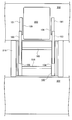
- FIG. 2 is a side view schematically showing the automatic warehouse.
- FIG. 3 is a top view showing the transfer device attached to the lifting platform.
- FIGS. 4A and 4B are views showing the attachment state of the contact body, where FIG. 4A is a side view, and
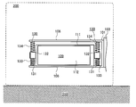
- FIG. 5 is a diagram schematically illustrating a state in which a load is being transferred from the first placement location to the second placement location.
- FIG. 6 is a diagram schematically illustrating a state in which the load is transferred to the second placement place.
- FIG. 7 is a diagram schematically illustrating an operation when the elastic body and the second elastic body are not provided.
- FIG. 8 is a diagram illustrating the concept of the transfer method of the sandwiching method.
- FIG. 1 is a perspective view showing a part of an automatic warehouse in which a stacker crane equipped with a transfer device is provided.
- an automatic warehouse 300 is a warehouse in which a loader 200 is automatically loaded and loaded on a rack 302 by a stacker crane 301 and is automatically unloaded. And a station 302 on which a luggage is placed at the time of loading and unloading.
- FIG. 2 is a side view schematically showing the automatic warehouse.
- the stacker crane 301 includes a casing formed by connecting a lower carriage 311 and an upper carriage 312 with a mast 313, and a configuration in which a lifting platform 316 is moved up and down along the mast 313 is adopted.
- the transfer device 100 is attached to the lifting platform 316.
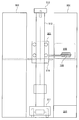
- FIG. 3 is a top view showing the transfer device attached to the lifting platform.
- the transfer device 100 is a device for transferring a load 200 between a rack 302 as a first placement location and a lifting platform 316 as a second placement location in a sandwiching manner.
- the arm 101, the contact body 109, the intermediate rail 103, the fixed rail 104, and the width changing rail 105 are provided.
- the arm 101 is a member that generates a force in the clamping direction (left-right direction in the figure) with respect to the luggage 200 via the contact body 109, and a space that exists on the side of the luggage 200 is used as an axis of the luggage transfer direction. It is a rod-shaped member that moves along.
- the fixed rail 104 is a member fixed to the lifting platform 316, and the intermediate rail 103 slides along the fixed rail 104.
- the intermediate rail 103 is a member that slidably holds the arm 101 and is slidably attached to the fixed rail 104, and has a function of projecting the arm 101 far away while maintaining a predetermined structural strength.
- the fixed rail 104, the intermediate rail 103, and the arm 101 constitute a telescopic structure, and the intermediate rail 103 is attached to the fixed rail 104 by a driving device (not shown).
- a driving device not shown
- the arm 101 slides so as to project with respect to the intermediate rail 103 in conjunction with the operation.
- the width changing rail 105 is a rail for moving the fixed rail 104 in the clamping direction (left and right in the figure) in order to adjust the interval of the arms 101 to clamp the luggage 200.
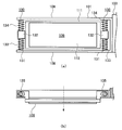
- FIG. 4A and 4B are diagrams showing the attachment state of the contact body, where FIG. 4A is a side view and FIG. 4B is a top view with a part of the arm cut away.
- the arm 101 has a contact body 109 attached thereto via a connector 130.
- the contact body 109 is a plate-like member that contacts the luggage 200.
- the contact body 109 includes a substrate 111 and a close contact portion 112.
- the board 111 is a highly rigid plate-like member that gives a clamping force to the luggage 200 in a planar shape, and is attached to the arm 101 via the connection tool 130 so as to protrude from the arm 101 to the luggage 200 side. Yes.
- the contact portion 112 is a portion that is in close contact with the luggage 200 and applies a force in the transfer direction to the luggage by friction.
- the close contact portion 112 is a thin plate-like rubber (elastomer), and is attached in a state of spreading over the entire surface of the substrate 111.
- connection tool 130 is in contact with the arm 101 so as to be movable in the vertical direction (vertical direction in FIG. 10A) without moving in the clamping direction axis (the arrow in FIG. 10B) with respect to the arm 101.
- connection tool 130 includes a guide bar 131, a sliding body 132, an elastic body 133, and a second elastic body 134.
- the guide rod 131 is a rod-like member that is attached to the two frames 108 that are attached in a protruding manner with a predetermined distance from the tip of the arm 101.
- the guide bar 131 has a cylindrical shape.
- the sliding body 132 is a member that is regulated by the guide rod 131 and slides along the guide rod 131.
- the sliding body 132 is provided so that a guide hole 135 through which the guide bar 131 is inserted penetrates in the vertical direction, and one end thereof is fixed to the contact body 109.
- the elastic body 133 is a member that supports the contact body 109 in an upward biased state with respect to the arm 101.
- the elastic body 133 is a chord spring that supports the contact body 109 via a sliding body 132 fixed to the contact body 109.
- the elastic body 133 is disposed so as to wrap around the outer periphery of the guide rod 131, and one end is in contact with the lower frame body 108 and the other end is in contact with the lower surface of the sliding body 132.
- the second elastic body 134 is a member that urges the contact body 109 downward with respect to the arm 101.
- the second elastic body 134 is a coiled spring that urges the contact body 109 downward via a sliding body 132 fixed to the contact body 109.
- the second elastic body 134 is disposed so as to wrap around the outer periphery of the guide bar 131, and has one end in contact with the upper frame body 108 and the other end in contact with the upper surface of the sliding body 132. In this state, even if vibration or the like occurs in the arm 101, it is possible to suppress fluttering of the contact body 109.
- the guide bar 131, the sliding body 132, the elastic body 133, and the second elastic body 134 form a pair, and are provided at one end and the other end of the contact body 109, respectively.
- the guide hole 135 provided in the sliding body 132 is a long hole extending in a direction perpendicular to the pinching direction axis in the vertical plane. As described above, the contact body 109 can tilt with respect to the guide bar 131 in the vertical plane.
- the lifting platform 316 is arranged at a position where the package 200 to be transferred is stored.
- the surface on which the luggage 200 is placed and the surface on which the luggage 200 is placed on the lifting platform 316 are adjusted to the same level and are close to each other.
- the intermediate rail 103 is protruded toward the rack 302 with respect to the fixed rail 104.
- the distance between the two arms 101 is adjusted to be slightly wider than the width of the load 200 to be transferred.
- the arm 101 protrudes toward the rack 302 with respect to the intermediate rail 103 until a predetermined arrangement is obtained.
- the fixed rail 104 is moved along the width changing rail 105, and the luggage 200 is sandwiched via the contact body 109.
- the contact body 109 is attached so as not to move in the clamping direction with respect to the arm 101, so that a sufficient clamping force can be generated between the contact body 109 and the luggage 200.
- the intermediate rail 103 is retracted relative to the fixed rail 104 and the arm 101 is retracted while being held.
- a static frictional force is generated in a direction perpendicular to the clamping force between the luggage 200 and the contact portion 112, and the luggage 200 is transferred to the stacker crane 301 side by the static frictional force.
- FIG. 5 is a diagram schematically showing a state in which a load is being transferred from the first placement location to the second placement location.
- the lifting platform 316 as the second mounting location is controlled to be slightly lower than the rack 302 as the first mounting location. Therefore, when the luggage 200 straddles the rack 302 and the lifting platform 316, the luggage 200 is slightly inclined. Even in this case, the contact body 109 is inclined with respect to the arm 101 due to the relationship between the guide rod 131 of the connector 130 and the guide hole 135 which is a long hole, and follows the inclination of the luggage 200. Therefore, it is possible to continue transfer between the luggage 200 and the close contact portion 112 without generating an excessive force such as a dynamic friction force.
- FIG. 6 is a diagram schematically showing a state in which the parcel is transferred to the second placement place.
- the abutment body 109 is in a state of falling with respect to the arm 101 following the luggage 200 placed on the lifting platform 316 disposed at a position lower than the rack 302. Accordingly, the luggage 200 and the contact portion 112 of the contact body 109 can be transferred from the rack 302 having a different level to the lifting platform 316 without rubbing, and the life of the contact portion 112 can be extended.
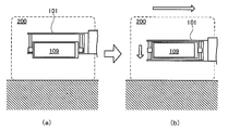
- the elastic body 133 and the 2nd elastic body 134 were used was demonstrated in the said embodiment, this invention is not limited to this. Even when the elastic body 133 and the second elastic body 134 are not used, the problem can be solved by raising and lowering the arm 101 as shown in FIG. Specifically, as shown in FIG. 7A, since the contact body 109 is not biased with respect to the arm 101, the contact body 109 is positioned at the lowermost position with respect to the arm 101. In this state, the arm 101 is brought closer to the luggage 200 and the contact body 109 is brought into contact with the luggage 200. Next, even if the arm 101 is moved downward as shown in FIG. 7B, the vertical position of the contact body 109 that is in contact with the luggage 200 does not change.
- the luggage 200 can be transferred, and there is a level difference between the first placement location and the second placement location. Even if it exists, it is possible to make the contact body 109 follow the behavior of the luggage 200.
- the present invention can be used in an automatic warehouse or a factory that transports luggage from a predetermined place to another place by an automatic transport vehicle.
Landscapes
- Engineering & Computer Science (AREA)
- Mechanical Engineering (AREA)
- Transportation (AREA)
- Structural Engineering (AREA)
- Civil Engineering (AREA)
- Life Sciences & Earth Sciences (AREA)
- Geology (AREA)
- Warehouses Or Storage Devices (AREA)
Abstract
Description
101 アーム
103 中間レール
104 固定レール
105 幅変更レール
108 枠体
109 当接体
111 基板
112 密着部
130 接続具
131 ガイド棒
132 摺動体
133 弾性体
134 第二弾性体
135 ガイド孔
200 荷物
300 自動倉庫
301 スタッカクレーン
302 ラック
303 ステーション
311 下部台車
312 上部台車
313 マスト
316 昇降台
Claims (3)
- 近接して配置される第一載置場所と第二載置場所との間を、挟持した荷物を滑らせて移載する移載装置であって、
荷物に当接する当接体と、
前記当接体を介して荷物に対し水平方向である挟持方向に力を発生させるアームと、
前記アームに対し前記当接体を挟持方向に移動することなく上下方向に移動可能に前記アームと前記当接体とを接続する接続具と
を備える移載装置。 - 前記接続具は、
前記アームに対し前記当接体を上方向の付勢状態で支持する弾性体を備える請求項1に記載の移載装置。 - 前記接続具はさらに、
前記アームに対し前記当接体を下方向に付勢する第二弾性体を備える請求項2に記載の移載装置。
Priority Applications (5)
| Application Number | Priority Date | Filing Date | Title |
|---|---|---|---|
| CN200980159744.5A CN102470984B (zh) | 2009-07-02 | 2009-07-02 | 移载装置 |
| US13/380,537 US9260242B2 (en) | 2009-07-02 | 2009-07-02 | Transfer apparatus |
| KR1020117029385A KR101348659B1 (ko) | 2009-07-02 | 2009-07-02 | 이송 장치 |
| PCT/JP2009/003071 WO2011001472A1 (ja) | 2009-07-02 | 2009-07-02 | 移載装置 |
| JP2011520672A JP5267668B2 (ja) | 2009-07-02 | 2009-07-02 | 移載装置 |
Applications Claiming Priority (1)
| Application Number | Priority Date | Filing Date | Title |
|---|---|---|---|
| PCT/JP2009/003071 WO2011001472A1 (ja) | 2009-07-02 | 2009-07-02 | 移載装置 |
Publications (1)
| Publication Number | Publication Date |
|---|---|
| WO2011001472A1 true WO2011001472A1 (ja) | 2011-01-06 |
Family
ID=43410574
Family Applications (1)
| Application Number | Title | Priority Date | Filing Date |
|---|---|---|---|
| PCT/JP2009/003071 Ceased WO2011001472A1 (ja) | 2009-07-02 | 2009-07-02 | 移載装置 |
Country Status (5)
| Country | Link |
|---|---|
| US (1) | US9260242B2 (ja) |
| JP (1) | JP5267668B2 (ja) |
| KR (1) | KR101348659B1 (ja) |
| CN (1) | CN102470984B (ja) |
| WO (1) | WO2011001472A1 (ja) |
Cited By (1)
| Publication number | Priority date | Publication date | Assignee | Title |
|---|---|---|---|---|
| CN115116908A (zh) * | 2022-08-22 | 2022-09-27 | 四川洪芯微科技有限公司 | 一种晶圆片沟槽腐蚀装置 |
Families Citing this family (6)
| Publication number | Priority date | Publication date | Assignee | Title |
|---|---|---|---|---|
| JP5928596B2 (ja) * | 2012-09-06 | 2016-06-01 | 村田機械株式会社 | 移載装置 |
| KR101479934B1 (ko) * | 2012-12-31 | 2015-01-12 | 주식회사 에스에프에이 | 승하강벨트장치 및 이를 구비한 자동반송시스템 |
| JP6930522B2 (ja) * | 2016-02-18 | 2021-09-01 | 株式会社ダイフク | 物品搬送装置 |
| IT201800004637A1 (it) * | 2018-04-18 | 2019-10-18 | Sistema di stoccaggio per stoccare articoli | |
| DE102020006668A1 (de) * | 2020-10-30 | 2022-05-05 | Smark Gmbh | Vorrichtung und Verfahren zum Bewegen von Ware in einem automatischen Warenlager |
| JP7655269B2 (ja) * | 2022-05-02 | 2025-04-02 | トヨタ自動車株式会社 | 車載荷役システム、スタッカ、および、荷物の受け渡し方法 |
Citations (3)
| Publication number | Priority date | Publication date | Assignee | Title |
|---|---|---|---|---|
| JPH07309408A (ja) * | 1994-05-17 | 1995-11-28 | Murata Mach Ltd | 物品移載装置 |
| JP2005138949A (ja) * | 2003-11-06 | 2005-06-02 | Murata Mach Ltd | 移載装置 |
| JP2008024493A (ja) * | 2006-07-25 | 2008-02-07 | Ihi Corp | 物品移載装置 |
Family Cites Families (8)
| Publication number | Priority date | Publication date | Assignee | Title |
|---|---|---|---|---|
| US2647650A (en) * | 1950-03-01 | 1953-08-04 | Clark Equipment Co | Combination clamp and rotating mechanism |
| US4852928A (en) * | 1984-02-16 | 1989-08-01 | Multivisions Corporation | Robotic end effectors |
| GB8924222D0 (en) * | 1989-10-27 | 1989-12-13 | Squires Michael | Load handling apparatus |
| JP3246642B2 (ja) * | 1994-05-16 | 2002-01-15 | 特種製紙株式会社 | 段積みしたシート状包装体の自動ピッキング方法及び装置 |
| US6039375A (en) * | 1998-01-28 | 2000-03-21 | Abb Flexible Automation, Inc. | Gripper assembly with integrated heat shield |
| JPH11268898A (ja) | 1998-03-20 | 1999-10-05 | Shin Meiwa Ind Co Ltd | 高所作業車の安全装置 |
| JP3701006B2 (ja) | 2000-05-31 | 2005-09-28 | 日本輸送機株式会社 | 保管設備 |
| JP2002167008A (ja) | 2000-11-30 | 2002-06-11 | Murata Mach Ltd | 物品移載装置 |
-
2009
- 2009-07-02 WO PCT/JP2009/003071 patent/WO2011001472A1/ja not_active Ceased
- 2009-07-02 KR KR1020117029385A patent/KR101348659B1/ko active Active
- 2009-07-02 CN CN200980159744.5A patent/CN102470984B/zh not_active Expired - Fee Related
- 2009-07-02 JP JP2011520672A patent/JP5267668B2/ja active Active
- 2009-07-02 US US13/380,537 patent/US9260242B2/en active Active
Patent Citations (3)
| Publication number | Priority date | Publication date | Assignee | Title |
|---|---|---|---|---|
| JPH07309408A (ja) * | 1994-05-17 | 1995-11-28 | Murata Mach Ltd | 物品移載装置 |
| JP2005138949A (ja) * | 2003-11-06 | 2005-06-02 | Murata Mach Ltd | 移載装置 |
| JP2008024493A (ja) * | 2006-07-25 | 2008-02-07 | Ihi Corp | 物品移載装置 |
Cited By (2)
| Publication number | Priority date | Publication date | Assignee | Title |
|---|---|---|---|---|
| CN115116908A (zh) * | 2022-08-22 | 2022-09-27 | 四川洪芯微科技有限公司 | 一种晶圆片沟槽腐蚀装置 |
| CN115116908B (zh) * | 2022-08-22 | 2023-01-10 | 四川洪芯微科技有限公司 | 一种晶圆片沟槽腐蚀装置 |
Also Published As
| Publication number | Publication date |
|---|---|
| JP5267668B2 (ja) | 2013-08-21 |
| CN102470984B (zh) | 2014-05-28 |
| US9260242B2 (en) | 2016-02-16 |
| CN102470984A (zh) | 2012-05-23 |
| US20120099952A1 (en) | 2012-04-26 |
| KR101348659B1 (ko) | 2014-01-08 |
| JPWO2011001472A1 (ja) | 2012-12-10 |
| KR20120019476A (ko) | 2012-03-06 |
Similar Documents
| Publication | Publication Date | Title |
|---|---|---|
| JP5267668B2 (ja) | 移載装置 | |
| KR102463265B1 (ko) | 물품 반송 설비 | |
| JP6559413B2 (ja) | 移載装置及び荷物取出方法 | |
| CN107804641B (zh) | 物品输送装置 | |
| JP6102759B2 (ja) | 物品搬送台車 | |
| TW200824996A (en) | Stacker crane | |
| US8459435B2 (en) | Operation platform for loading and unloading workpieces | |
| KR20130126692A (ko) | 천정 반송차 | |
| CN112010049B (zh) | 移载装置 | |
| JP2011020794A (ja) | 移載装置 | |
| JP2011246223A (ja) | 自動倉庫 | |
| JP2016020260A (ja) | 搬送車 | |
| JP5003621B2 (ja) | センタリング装置 | |
| CN108423398A (zh) | 运料机构 | |
| JP2021160857A (ja) | 把持装置、荷役装置、荷役制御装置、荷役制御方法及びコンピュータプログラム | |
| CN210122472U (zh) | 叉式升降搬运车 | |
| JP6913318B2 (ja) | 重量物横移動用のリフト | |
| US20210395025A1 (en) | Article Transport Facility | |
| JP6812675B2 (ja) | 走行式移載装置 | |
| JP2011020818A (ja) | カセットの位置決めクランプ装置 | |
| CN116462133A (zh) | 一种货叉用限位装置及货叉 | |
| JP3202445U (ja) | 搬送治具 | |
| JP2007050964A (ja) | 物品の荷姿監視システム | |
| JP6527810B2 (ja) | フロアリフト | |
| JP2013086917A (ja) | 自動倉庫 |
Legal Events
| Date | Code | Title | Description |
|---|---|---|---|
| WWE | Wipo information: entry into national phase |
Ref document number: 200980159744.5 Country of ref document: CN |
|
| 121 | Ep: the epo has been informed by wipo that ep was designated in this application |
Ref document number: 09846767 Country of ref document: EP Kind code of ref document: A1 |
|
| WWE | Wipo information: entry into national phase |
Ref document number: 2011520672 Country of ref document: JP |
|
| ENP | Entry into the national phase |
Ref document number: 20117029385 Country of ref document: KR Kind code of ref document: A |
|
| WWE | Wipo information: entry into national phase |
Ref document number: 13380537 Country of ref document: US |
|
| NENP | Non-entry into the national phase |
Ref country code: DE |
|
| 122 | Ep: pct application non-entry in european phase |
Ref document number: 09846767 Country of ref document: EP Kind code of ref document: A1 |