WO2010143357A1 - ポリオルガノシロキサン組成物およびその硬化体 - Google Patents
ポリオルガノシロキサン組成物およびその硬化体 Download PDFInfo
- Publication number
- WO2010143357A1 WO2010143357A1 PCT/JP2010/003242 JP2010003242W WO2010143357A1 WO 2010143357 A1 WO2010143357 A1 WO 2010143357A1 JP 2010003242 W JP2010003242 W JP 2010003242W WO 2010143357 A1 WO2010143357 A1 WO 2010143357A1
- Authority
- WO
- WIPO (PCT)
- Prior art keywords
- tte
- polyorganosiloxane
- tmos
- cured product
- pdms
- Prior art date
- Legal status (The legal status is an assumption and is not a legal conclusion. Google has not performed a legal analysis and makes no representation as to the accuracy of the status listed.)
- Ceased
Links
Images









Classifications
-
- C—CHEMISTRY; METALLURGY
- C08—ORGANIC MACROMOLECULAR COMPOUNDS; THEIR PREPARATION OR CHEMICAL WORKING-UP; COMPOSITIONS BASED THEREON
- C08G—MACROMOLECULAR COMPOUNDS OBTAINED OTHERWISE THAN BY REACTIONS ONLY INVOLVING UNSATURATED CARBON-TO-CARBON BONDS
- C08G79/00—Macromolecular compounds obtained by reactions forming a linkage containing atoms other than silicon, sulfur, nitrogen, oxygen, and carbon with or without the latter elements in the main chain of the macromolecule
-
- C—CHEMISTRY; METALLURGY
- C08—ORGANIC MACROMOLECULAR COMPOUNDS; THEIR PREPARATION OR CHEMICAL WORKING-UP; COMPOSITIONS BASED THEREON
- C08G—MACROMOLECULAR COMPOUNDS OBTAINED OTHERWISE THAN BY REACTIONS ONLY INVOLVING UNSATURATED CARBON-TO-CARBON BONDS
- C08G77/00—Macromolecular compounds obtained by reactions forming a linkage containing silicon with or without sulfur, nitrogen, oxygen or carbon in the main chain of the macromolecule
- C08G77/04—Polysiloxanes
- C08G77/14—Polysiloxanes containing silicon bound to oxygen-containing groups
- C08G77/16—Polysiloxanes containing silicon bound to oxygen-containing groups to hydroxy groups
-
- C—CHEMISTRY; METALLURGY
- C08—ORGANIC MACROMOLECULAR COMPOUNDS; THEIR PREPARATION OR CHEMICAL WORKING-UP; COMPOSITIONS BASED THEREON
- C08G—MACROMOLECULAR COMPOUNDS OBTAINED OTHERWISE THAN BY REACTIONS ONLY INVOLVING UNSATURATED CARBON-TO-CARBON BONDS
- C08G77/00—Macromolecular compounds obtained by reactions forming a linkage containing silicon with or without sulfur, nitrogen, oxygen or carbon in the main chain of the macromolecule
- C08G77/48—Macromolecular compounds obtained by reactions forming a linkage containing silicon with or without sulfur, nitrogen, oxygen or carbon in the main chain of the macromolecule in which at least two but not all the silicon atoms are connected by linkages other than oxygen atoms
- C08G77/58—Metal-containing linkages
-
- C—CHEMISTRY; METALLURGY
- C08—ORGANIC MACROMOLECULAR COMPOUNDS; THEIR PREPARATION OR CHEMICAL WORKING-UP; COMPOSITIONS BASED THEREON
- C08K—Use of inorganic or non-macromolecular organic substances as compounding ingredients
- C08K5/00—Use of organic ingredients
- C08K5/04—Oxygen-containing compounds
- C08K5/05—Alcohols; Metal alcoholates
- C08K5/057—Metal alcoholates
-
- C—CHEMISTRY; METALLURGY
- C08—ORGANIC MACROMOLECULAR COMPOUNDS; THEIR PREPARATION OR CHEMICAL WORKING-UP; COMPOSITIONS BASED THEREON
- C08K—Use of inorganic or non-macromolecular organic substances as compounding ingredients
- C08K5/00—Use of organic ingredients
- C08K5/54—Silicon-containing compounds
- C08K5/541—Silicon-containing compounds containing oxygen
- C08K5/5415—Silicon-containing compounds containing oxygen containing at least one Si—O bond
-
- C—CHEMISTRY; METALLURGY
- C09—DYES; PAINTS; POLISHES; NATURAL RESINS; ADHESIVES; COMPOSITIONS NOT OTHERWISE PROVIDED FOR; APPLICATIONS OF MATERIALS NOT OTHERWISE PROVIDED FOR
- C09J—ADHESIVES; NON-MECHANICAL ASPECTS OF ADHESIVE PROCESSES IN GENERAL; ADHESIVE PROCESSES NOT PROVIDED FOR ELSEWHERE; USE OF MATERIALS AS ADHESIVES
- C09J183/00—Adhesives based on macromolecular compounds obtained by reactions forming in the main chain of the macromolecule a linkage containing silicon, with or without sulfur, nitrogen, oxygen, or carbon only; Adhesives based on derivatives of such polymers
- C09J183/14—Adhesives based on macromolecular compounds obtained by reactions forming in the main chain of the macromolecule a linkage containing silicon, with or without sulfur, nitrogen, oxygen, or carbon only; Adhesives based on derivatives of such polymers in which at least two but not all the silicon atoms are connected by linkages other than oxygen atoms
Definitions
- the present invention relates to a polyorganosiloxane composition and a cured product thereof.
- polyorganosiloxane compositions have been used for adhesives and sealing materials because they exhibit excellent weather resistance and durability when cured.
- a cured product of a polyorganosiloxane composition tends to require higher strength.
- a polyorganosiloxane composition in which a filler made of an inorganic or organic compound is mixed is known (see Patent Document 1).
- the cured product of the conventional polyorganosiloxane composition has the following problems.
- the polyorganosiloxane composition disclosed in Patent Document 1 requires a step of mixing a filler during the production thereof.
- the filler must be surface treated to uniformly disperse the filler in the cured product, or fine particles with a narrower particle size distribution must be used in order to achieve high strength. It was difficult to obtain a cured product.
- the polyorganosiloxane composition disclosed in Patent Document 2 uses a compound having a bisphenol A skeleton known as a kind of environmental hormone, there is a high possibility that it will lead to environmental pollution.
- the present invention has been made in view of such a problem, and an object of the present invention is to provide a polyorganosiloxane composition that can obtain a cured product having high strength and has a small influence on the environment, and the cured product thereof. To do.
- the present inventors have mixed silicon alkoxide, titanium alkoxide, and hydroxycarboxylic acid ester with polyorganosiloxane, thereby improving the strength of the cured product.
- the present inventors have succeeded in producing a polyorganosiloxane composition and a cured product thereof, which are increased and reduce substances that have a risk of adversely affecting the environment as much as possible.
- the present invention relates to (A) a polyorganosiloxane in which at least one terminal in one molecule is silanol-modified, (B) 0.5 to 30 mol of silicon alkoxide with respect to 1 mol of polyorganosiloxane, and (C Polyorganosiloxane composition comprising 0.01) to 2 moles of titanium alkoxide per mole of polyorganosiloxane, and (D) 0.01 to 2 moles of hydroxycarboxylic acid ester per mole of polyorganosiloxane. It is a thing.
- Another aspect of the present invention is a polyorganosiloxane composition further comprising an inorganic filler occupying 2 to 30% by weight with respect to the total weight of the polyorganosiloxane composition.
- Another invention of the present invention is a polyorganosiloxane composition containing 5 to 20 mol of silicon alkoxide (B) with respect to 1 mol of polyorganosiloxane (A).
- Another aspect of the present invention is a polyorganosiloxane composition in which the hydroxycarboxylic acid ester (D) is a malic acid dialkyl ester.
- Another aspect of the present invention relates to a polyorganosiloxane comprising, in particular, 0.3 to 0.5 mol of titanium alkoxide (C) and hydroxycarboxylic acid ester (D), respectively, per mol of polyorganosiloxane (A). It is a composition.
- Another aspect of the present invention is a cured polyorganosiloxane composition obtained by curing any of the above polyorganosiloxane compositions.
- Another aspect of the present invention is: (A) a polyorganosiloxane in which at least one terminal in one molecule is silanol-modified, and (B) 0.5 to 4 mol of silicon alkoxide with respect to 1 mol of the polyorganosiloxane. (C) 0.01 to 0.5 moles of titanium alkoxide with respect to 1 mole of the polyorganosiloxane, and (D) 0.01 to 0.5 moles of hydroxycarboxylic acid with respect to 1 mole of the polyorganosiloxane.
- Another aspect of the present invention is a polyorganosiloxane composition in which the hydroxycarboxylic acid ester is a malic acid dialkyl ester.
- a polyorgano containing 0.02 to 0.1 mol of the titanium alkoxide (C) and the hydroxycarboxylic acid ester (D) with respect to 1 mol of the polyorganosiloxane (A). It is a siloxane composition.
- Another aspect of the present invention is a cured polyorganosiloxane composition obtained by curing any of the above polyorganosiloxane compositions.
- a cured product having high strength can be obtained, and a polyorganosiloxane composition having a small influence on the environment and a cured product thereof can be obtained.
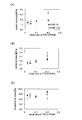
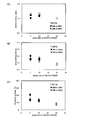
- FIG. 1 shows a TEOS-TTE-MA 0.025 system solution, a TEOS-TTE-MA 0.05 system solution, and a TEOS-TTE-MA0.1 system solution at 25 ° C. and a humidity of 50% ⁇ 10% R.S. H. It is a graph which shows the tensile characteristic of each hardened
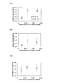
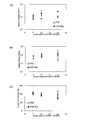
- FIG. 2 shows a TEOS-TTE 0.025 system solution, a TEOS-TTE 0.05 system solution, a TEOS-TTE 0.1 system solution, and a TEOS-TTE 0.2 system solution at 25 ° C.
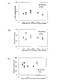
- FIG. 3 shows that a TMOS-TTE-MA0.01 system solution, a TMOS-TTE-MA0.025 system solution, and a TMOS-TTE-MA0.05 system solution are each 25 ° C., humidity 50% ⁇ 10% R.D. H. It is a graph which shows the tensile characteristic of each hardened
- FIG. 3 shows that a TMOS-TTE-MA0.01 system solution, a TMOS-TTE-MA0.025 system solution, and a TMOS-TTE-MA0.05 system solution are each 25 ° C., humidity 50% ⁇ 10% R.D. H. It is a graph which shows the tensile characteristic of each hardened
- FIG. 4 shows a TMOS-TTE 0.025 system solution and a TMOS-TTE 0.08 system solution at 25 ° C. and a humidity of 50% ⁇ 10% R.E. H. It is a graph which shows the tensile characteristic of each hardened
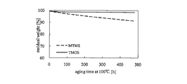
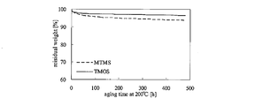
- FIG. 5 is a graph showing the relationship between the elapsed time after the various test pieces are placed in a thermostatic bath maintained at 100 ° C. and 200 ° C. and the residual weight ratio.
- FIG. 5 is a graph showing the relationship between the elapsed time after the various test pieces are placed in a thermostatic bath maintained at 100 ° C. and 200 ° C. and the residual weight ratio.
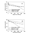
- FIG. 6 shows three types of test pieces, a TMOS-TTE-MA 0.025 cured product, a TMOS-TTE 0.025 cured product, and a TMOS-TTE 0.08 cured product, which are kept at 150 ° C. and 200 ° C. It is a graph which shows the relationship between the elapsed time after putting in a tank, and a residual weight rate.
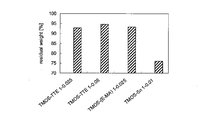
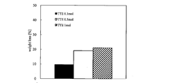
- FIG. 7 is a graph showing the residual weight ratios of test pieces of various TMOS-based cured products evaluated under conditions of holding at 120 ° C. for 120 hours.
- FIG. 8 shows tensile properties of the PDMS-MTMS-TTE-MA-R972 cured body (7) and the PDMS-TMOS-TTE-MA-R972 cured body (7) when the molar ratio of silicon alkoxide is changed. It is a graph which shows.
- FIG. 9 shows a PDMS-MTMS-TTE-MA-R972-based cured product (7), PDMS-MTMS-TTE-MA-R972-based cured product 100 ° C. (20) and PDMS- when the molar ratio of MTMS is changed.
- 3 is a graph showing tensile properties of a cured MTMS-TTE-MA-R972 system at 200 ° C. (20).
- FIG. 10 shows PDMS-TMOS-TTE-MA-R972-based cured product (7), PDMS-TMOS-TTE-MA-R972-based cured product 100 ° C. (20) and PDMS- when the molar ratio of TMOS is changed.
- 6 is a graph showing tensile properties of a TMOS-TTE-MA-R972 cured body at 200 ° C. (20).
- FIG. 11 is a graph showing tensile properties of the PDMS-MTMS-TTE-MA-R972 cured product (7) and the PDMS-MTMS-TTE-R972 cured product (7) when the MTMS molar ratio is changed. It is.
- FIG. 12 shows a PDMS-MTMS-TTE-MA-R972-based cured product (7) and a PDMS-TMOS-TTE-MA-R972-based cured product (7) and MTMS or TMOS prepared by changing the molar ratio in the range of 5 to 20 molar ratio ( It is a graph which shows the relationship between the elapsed time after putting 7) in the thermostat kept at 100 degreeC, and a residual weight percentage.
- FIG. 13 shows a PDMS-MTMS-TTE-MA-R972-based cured body (7) and a PDMS-TMOS-TTE-MA-R972-based cured body (7) and MTMS or TMOS prepared by changing MTMS or TMOS in the range of 5 to 20 molar ratio. It is a graph which shows the relationship between the elapsed time after putting 7) in the thermostat kept at 200 degreeC, and a residual weight percentage.
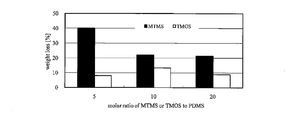
- FIG. 14 shows a PDMS-MTMS-TTE-MA-R972-based cured body (7) and a PDMS-TMOS-TTE-MA-R972-based cured body (7) and MTMS or TMOS prepared by changing MTMS or TMOS in a range of 5 to 20 molar ratio ( It is a figure which compares and shows each weight decreasing rate when 7) is hold
- FIG. 15 shows the tensile properties of the PDMS-MTMS-TTE-MA-R972 cured body (7) and PDMS-MTMS-TTE-R972 cured body (7) prepared by changing the molar ratio of TTE and MA. It is a graph to show.
- FIG. 16 shows a PDMS-MTMS-TTE-MA-R972-based cured product (7) and a PDMS-TMOS-TTE-MA-R972-based cured product (7) when both TTE and MA are in a 0.3 molar ratio. It is a graph which shows the relationship between the elapsed time after putting in the thermostat kept at 100 degreeC, and a residual weight percentage.
- FIG. 17 shows a PDMS-MTMS-TTE-MA-R972-based cured product (7) and a PDMS-TMOS-TTE-MA-R972-based cured product (7) when both TTE and MA are in a 0.3 molar ratio.
- FIG. 18 shows a constant temperature bath in which a PDMS-MTMS-TTE-MA-R972-based cured product (7) prepared by changing both TTE and MA in a range of 0.2 to 0.5 molar ratio is maintained at 100 ° C. It is a figure which shows the relationship between the elapsed time after putting in and residual weight ratio.
- FIG. 19 shows a constant temperature bath in which a PDMS-MTMS-TTE-MA-R972-based cured product (7) prepared by changing both TTE and MA in a range of 0.2 to 0.5 molar ratio is maintained at 200 ° C.
- FIG. 20 shows a PDMS-MTMS-TTE-R972-based cured product (7) produced by changing TTE within a range of 0.3 to 1.0 molar ratio after being placed in a thermostatic bath maintained at 100 ° C. It is a figure which shows the relationship between elapsed time and residual weight percentage.
- FIG. 21 shows a PDMS-MTMS-TTE-R972-based cured product (7) produced by changing TTE within a range of 0.3 to 1.0 molar ratio after being placed in a thermostatic bath maintained at 200 ° C. It is a figure which shows the relationship between elapsed time and residual weight percentage.
- FIG. 20 shows a PDMS-MTMS-TTE-R972-based cured product (7) produced by changing TTE within a range of 0.3 to 1.0 molar ratio after being placed in a thermostatic bath maintained at 200 ° C. It is a figure which shows the relationship between elapsed time and residual weight percentage.
- FIG. 20 shows a PD
- FIG. 22 shows a PDMS-MTMS-TTE-MA-R972 cured body (7) and a PDMS-TMOS-TTE-MA-R972 cured body (7) when both TTE and MA are in a 0.3 molar ratio. It is a figure which compares and shows each weight reduction rate when it hold
- FIG. 23 shows a PDMS-MTMS-TTE-MA-R972-based cured product (7) prepared by changing both TTE and MA in the range of 0.2 to 0.5 molar ratio, and kept at 120 ° C. for 120 hours. It is a figure which compares and shows each weight reduction
- the polyorganosiloxane composition according to this embodiment is (A) a polyorganosiloxane in which at least one terminal in one molecule is silanol-modified, (B) 0.5 to 4 moles of silicon alkoxide per mole of the polyorganosiloxane; (C) 0.01 to 0.5 mole of titanium alkoxide with respect to 1 mole of the polyorganosiloxane; (D) A sol or gel composition containing 0.01 to 0.5 mol of hydroxycarboxylic acid ester per mol of the polyorganosiloxane.
- a sol or gel composition containing 0.01 to 0.5 mol of hydroxycarboxylic acid ester per mol of the polyorganosiloxane.
- Terminal silanol-modified polyorganosiloxane The terminal silanol-modified polyorganosiloxane that can be used in this embodiment is represented by the following general formula (1).
- R 1 and R 2 are each independently a linear or branched alkyl group having 1 to 20 carbon atoms, a cycloalkyl group having 4 to 10 carbon atoms, or an aryl or aryl-substituted carbon atom having 6 to 10 carbon atoms. It is a hydrogen group.
- Examples of the linear or branched alkyl group having 1 to 20 carbon atoms include methyl, ethyl, n-propyl, i-propyl, n-butyl, i-butyl, s-butyl, t-butyl, pentyl, neopentyl, and hexyl.
- Heptyl, octyl, nonyl, decyl, undecyl, dodecyl, and the like can be given as preferred examples.
- suitable cycloalkyl groups having 4 to 10 carbon atoms include functional groups such as cyclopentyl and cyclohexyl.
- aryl group or aryl-substituted hydrocarbon group having 6 to 10 carbon atoms include phenyl, toluyl, xylyl, ethylphenyl, benzyl, phenethyl and the like.
- a particularly preferred terminal silanol-modified polyorganosiloxane is a both-end silanol-modified polydimethylsiloxane.
- the viscosity of the terminal silanol-modified polyorganosiloxane at 30 ° C. is 1 to 500 mPa ⁇ s, preferably 5 to 100 mPa ⁇ s, more preferably 10 to 50 mPa ⁇ s.
- the mass average molecular weight (Mw) of the terminal silanol-modified polyorganosiloxane is preferably 500 to 3000, more preferably 700 to 2000, and still more preferably 900 to 1200.
- Silicon alkoxide As the silicon alkoxide, one or a mixture of two or more tri- or tetraalkoxysilanes having a lower alkyl group having 1 to 4 carbon atoms may be mentioned. Specific examples thereof include trimethoxysilane, tetramethoxysilane, triethoxysilane, tetraethoxysilane, tetrapropoxysilane, and tetrabutoxysilane. Moreover, these oligomers can also be used. A particularly preferred example of silicon alkoxide is tetramethoxysilane or tetraethoxysilane.
- Silicon alkoxide is preferably contained in the composition in an amount of 0.5 to 4 mol, more preferably 0.7 to 2 mol, relative to 1 mol of polyorganosiloxane. Silicon alkoxide functions as a cross-linking agent that cross-links the polyorganosiloxane molecules. For this reason, if the amount of silicon alkoxide is too small, crosslinking of the polyorganosiloxane becomes insufficient. If the amount is too large, there is an excess of polyorganosiloxane modified at both ends by alkoxide at the initial stage of curing, and the curing reaction tends to be slow. There is. More preferably, the silicon alkoxide is present in the same mole as 1 mole of polyorganosiloxane.
- Titanium alkoxide As the titanium alkoxide, one or a mixture of two or more of titanium tetraethoxide, titanium tetrapropoxide, titanium tetraisopropoxide, titanium tetrabutoxide, titanium tetraisobutoxide, titanium tetraisopropenyl oxide, etc. Is mentioned. Moreover, these oligomers can also be used. Preferable examples of the titanium alkoxide are titanium tetraethoxide, titanium tetraisopropoxide, or titanium tetrabutoxide, and among these, titanium tetraethoxide is preferable.
- the titanium alkoxide is preferably contained in the composition in an amount of 0.01 to 0.5 mol, preferably 0.02 to 0.1 mol, relative to 1 mol of polyorganosiloxane.
- the titanium alkoxide When there is too little titanium alkoxide, it will become difficult to harden
- the hydroxycarboxylic acid ester is one or a mixture of two or more products obtained by ester reaction of a hydroxycarboxylic acid having 3 to 6 carbon atoms with an alcohol having 1 to 20 carbon atoms.
- Examples of the hydroxycarboxylic acid include monocarboxylic acids such as lactic acid and glyceric acid, dicarboxylic acids such as malic acid and tartaric acid, and tricarboxylic acids such as citric acid.
- Examples of the alcohol include methyl alcohol, ethyl alcohol, n-propyl alcohol, i-propyl alcohol, n-butyl alcohol, i-butyl alcohol, ter-butyl alcohol, pentyl alcohol, hexyl alcohol, heptyl alcohol, octyl alcohol, nonyl alcohol, Examples thereof include aliphatic saturated alcohols such as decyl alcohol, lauryl alcohol, myristyl alcohol, palmityl alcohol, and stearyl alcohol.
- hydroxycarboxylic acid ester produced by the ester reaction between the hydroxycarboxylic acid and the alcohol examples include, for example, malic acid ester, citric acid ester, lactic acid ester, tartaric acid ester, glycol monoester, glycerin monoester, glycerin diester, There may be mentioned ricinoleic acid esters.
- malic acid ester, citric acid ester, lactic acid ester, and tartaric acid ester are preferable, and among them, malic acid ester is preferable.
- a malic acid dialkyl ester is particularly preferable.
- malic acid dialkyl ester examples include malic acid dimethyl ester, malic acid diethyl ester, malic acid dipropyl ester, malic acid dibutyl ester, malic acid dihexyl ester, acetyl malic acid dioctyl ester, malic acid monoethyl monooctyl ester and the like. Can be mentioned. Among these, malic acid diethyl ester and malic acid dibutyl ester are particularly preferable.
- the hydroxycarboxylic acid ester is preferably contained in the composition in the range of 0.01 to 0.5 mol, particularly in the range of 0.02 to 0.1 mol, relative to 1 mol of polyorganosiloxane. It is preferably contained in the inside. Furthermore, the hydroxycarboxylic acid ester is contained in the composition in an equimolar amount with the titanium alkoxide, preferably in the range of 0.01 to 0.5 mol, more preferably in the range of 0.02 to 0.1 mol. .
- the atmosphere of stirring either a sealed atmosphere or an open atmosphere can be selected.
- mixed liquid 1 in which polyorganosiloxane and silicon alkoxide are mixed, and mixing in which titanium alkoxide and hydroxycarboxylic acid ester are separately mixed It is preferable to mix the liquid 2.
- the reaction would be more uniform if mixed liquid 1 and mixed liquid 2 were mixed separately. It is.
- the mixed solution 1 is prepared by stirring at a temperature of 25 to 60 ° C., preferably 30 to 50 ° C., more preferably 35 to 45 ° C.
- the stirring environment is preferably an inert gas atmosphere.
- the mixed solution 2 is prepared by stirring in a temperature range of 15 to 40 ° C., preferably 20 to 35 ° C., more preferably 25 to 30 ° C.
- the stirring environment is preferably an inert gas atmosphere.
- Method for producing a cured product of polyorganosiloxane composition For example, the polyorganosiloxane composition according to the embodiment obtained by the above-described method is subjected to humidity at a temperature of 15 to 45 ° C, preferably 20 to 30 ° C. 50% ⁇ 20% R.D. H.
- the cured product of the polyorganosiloxane composition can be obtained by leaving it in an environment preferably maintained in an atmosphere of 50% ⁇ 10%.
- the polyorganosiloxane composition according to the embodiment has an advantage of being cured even at a so-called room temperature.
- the standing time until curing is preferably 0.1 hour or longer, particularly 100 hours or longer, more preferably 150 hours or longer, and further preferably 200 hours or longer.
- the polyorganosiloxane composition according to this embodiment is (A) a polyorganosiloxane in which at least one terminal in one molecule is silanol-modified, (B) 0.5 to 30 moles of silicon alkoxide per mole of the polyorganosiloxane; (C) 0.01 to 2.0 moles of titanium alkoxide with respect to 1 mole of the polyorganosiloxane; (D) A sol or gel composition containing at least 0.01 to 2.0 mol of hydroxycarboxylic acid ester per mol of the polyorganosiloxane.
- the polyorganosiloxane composition according to this embodiment includes (E) an inorganic filler occupying 2 to 30% by weight with respect to the total weight of the polyorganosiloxane composition. It is more preferable to contain.
- an inorganic filler occupying 2 to 30% by weight with respect to the total weight of the polyorganosiloxane composition. It is more preferable to contain.
- the weight average molecular weight (Mw) of the terminal silanol-modified polyorganosiloxane is preferably 500 to 100,000, more preferably 700 to 50,000, and still more preferably 900 to 40,000. Others are the same as those in the first embodiment, and thus description thereof is omitted.
- Silicon alkoxide examples include tri- or tetraalkoxysilane having a lower alkyl group having 1 to 4 carbon atoms, as in the first embodiment. Specific examples thereof include methyltrimethoxysilane, trimethoxysilane, tetramethoxysilane, triethoxysilane, tetraethoxysilane, tetrapropoxysilane, and tetrabutoxysilane. Moreover, these oligomers can also be used. Particularly preferred examples of the silicon alkoxide are methyltrimethoxysilane, tetramethoxysilane or tetraethoxysilane.
- Silicon alkoxide has a composition in the range of 0.5 to 30 moles per mole of polyorganosiloxane, and in the range of 1 to 25 moles when Mw of the terminal silanol-modified polyorganosiloxane is 10,000 or more. It is preferably contained in the product.
- methyltrimethoxysilane is used for the silicon alkoxide and the polyorganosiloxane composition contains an inorganic filler, it is more preferable to include 5 mol or more of methyltrimethoxysilane with respect to 1 mol of polyorganosiloxane. preferable.
- tetramethoxysilane when used for the silicon alkoxide and an inorganic filler is contained in the polyorganosiloxane composition, it is preferable to contain 20 mol or less of tetramethoxysilane with respect to 1 mol of polyorganosiloxane.
- Titanium alkoxide The titanium alkoxide is preferably contained in the composition in an amount of 0.01 to 2 mol, preferably 0.02 to 1 mol, relative to 1 mol of polyorganosiloxane. Specific alkoxides and preferred alkoxides belonging to the titanium alkoxide are the same as those described in the first embodiment.
- (D) Hydroxycarboxylic acid ester The hydroxycarboxylic acid ester is preferably contained in the composition in an amount of 0.01 to 2 mol, preferably 0.02 to 1 mol, relative to 1 mol of polyorganosiloxane. . In particular, it is more preferable to use the same mole as the titanium alkoxide. Specific esters and preferred esters belonging to the hydroxycarboxylic acid ester are the same as those described in the first embodiment.
- inorganic filler examples include particulate, plate-like, or fibrous fillers of inorganic oxides such as silica, titanium oxide, alumina, and zirconia.
- silica having a small particle size and good compatibility with the polyorganosiloxane composition is preferable.
- the content of the inorganic filler is 2 to 30% by weight, more preferably 5 to 20% by weight, still more preferably 7 to 15% by weight, based on the total weight of the polyorganosiloxane composition including the inorganic filler.
- Process for producing polyorganosiloxane composition Polyorganosiloxane having at least one terminal in a molecule modified with silanol, 0.5 to 30 mol of silicon alkoxide per mol of the polyorganosiloxane, and polyorganosiloxane 1 0.01 to 2 moles of titanium alkoxide per mole, 0.01 to 2 moles of hydroxycarboxylic acid ester per mole of the above polyorganosiloxane, and 2 to 2 weight based on the total weight of the polyorganosiloxane composition.
- An inorganic filler occupying 30% by weight is put into a container and stirred at a temperature of 20 to 120 ° C., preferably 25 to 80 ° C., more preferably 30 to 50 ° C.
- the atmosphere of stirring either a sealed atmosphere or an open atmosphere can be selected.
- nitrogen gas or argon gas is preferably flowed.
- the absorption peak at 920 cm ⁇ 1 due to the Si—O—Ti bond by FT-IR measurement and the peak due to silicon alkoxide by GPC measurement were confirmed, and it was confirmed that these peaks disappeared. It is preferable to end the stirring. This is to confirm that the silanol group of PDMS and the alkoxy group of silicon alkoxide have reacted.
- mixed liquid 1 in which polyorganosiloxane and silicon alkoxide are mixed, and mixing in which titanium alkoxide and hydroxycarboxylic acid ester are separately mixed It is preferable to prepare the liquid 2 and mix them.
- adding an inorganic filler it is preferable to add the said inorganic filler to either the liquid mixture 1, the liquid mixture 2, or both.
- the preparation of a plurality of mixed liquids in this way is that the mixed liquid 1 and the mixed liquid 2 are separated from the polyorganosiloxane and silicon alkoxide solution, rather than the hydroxycarboxylic acid ester is coordinated to the titanium alkoxide. This is because the reaction is considered to be more uniform when mixed together.
- the mixed solution 1 is prepared by stirring at a temperature of 25 to 60 ° C., preferably 30 to 50 ° C., more preferably 35 to 45 ° C.
- the stirring environment is preferably an inert gas atmosphere.
- the mixed solution 2 is prepared by stirring in a temperature range of 15 to 40 ° C., preferably 20 to 35 ° C., more preferably 25 to 30 ° C.
- the stirring environment is preferably an inert gas atmosphere.
- Method for producing cured product of polyorganosiloxane composition For example, the polyorganosiloxane composition according to the second embodiment obtained by the above-described method is heated to a temperature of 15 to 45 ° C, preferably 20 to 30 ° C. Humidity 50% ⁇ 20% R.B. H.
- the cured product of the polyorganosiloxane composition can be obtained by leaving it in an environment preferably maintained in an atmosphere of 50% ⁇ 10%.
- the polyorganosiloxane composition according to the second embodiment has an advantage that it is cured at a so-called room temperature.
- the standing time until curing is preferably 0.1 hour or longer, particularly 100 hours or longer, more preferably 150 hours or longer, and further preferably 200 hours or longer.
- the polyorganosiloxane composition according to the second embodiment can be allowed to cure by allowing it to stand at room temperature or higher, for example, at 50 to 300 ° C. for 0.1 hour or longer.
- the curing temperature is particularly preferably in the range of 80 to 250 ° C.
- the standing time until curing is preferably 0.1 hour or longer, particularly 100 hours or longer, more preferably 150 hours or longer, and further preferably 200 hours or longer.
- TTE-MA-based solution was stirred under a sealed atmosphere by flowing a dry nitrogen gas through a glass container, inserting a stirring rod with a propeller, and immersing it in an oil bath maintained at 40 ° C.
- TTE-based cured product a cured product obtained by curing a solution in which PDMS, TEOS, and TTE are mixed (hereinafter referred to as “TTE-based solution”), and ethyl acetoacetate (EAcAc) on PDMA, TEOS, and TTE are used.
- TTE-EAcAc-based cured body A cured body obtained by curing a solution in which the coordinated materials were mixed (hereinafter referred to as “TTE-EAcAc-based solution”) was also produced.
- PDMS 50 g, TEOS 10.417 g, and TTE 0.570 g were put in this order in a glass container with a lid (capacity: 200 ml) in a nitrogen-substituted glove box, and the lid of the glass container was closed.
- PDMS: TEOS: TTE 1: 1: 0.05 in molar ratio).
- TTE-EAcAc-based cured body 50 g of PDMS, 10.417 g of TEOS, 0.570 g of TTE, and 0.325 g of EAcAc were put in this order in a glass container with a lid (capacity: 200 ml), and the lid of the glass container was closed (mol).
- PDMS: TEOS: TTE: EAcAc 1: 1: 0.05: 0.05).
- each glass container with the lid closed outside the glove box was taken out.
- TTE-based solution and the TTE-EAcAc-based solution were treated in the same manner as the above-mentioned TTE-MA-based solution, and the peaks due to Si—O—Ti bonds and TEOS disappeared.
- the TTE-EAcAc solution was confirmed after 96 hours. Thereafter, each solution was developed in a petri dish, and the temperature was 25 ° C. and the humidity was 50% ⁇ 10% R.D. H. This was left for 168 hours in a box kept under the atmosphere of TTE to obtain a TTE cured product and a TTE-EAcAc cured product.
- Table 1 shows the evaluation results of the tensile properties of the TTE-MA based cured body, the TTE based cured body, and the TTE-EAcAc based cured body.
- the elongation at break (%) is indicated by the ratio of the elongation to the original length.
- TTE-MA-based cured body was superior in elastic modulus and breaking strength compared to the TTE-based cured body and the TTE-EAcAc-based cured body. This suggests that the degree of cross-linking of the TTE-MA-based cured body is superior to other cured bodies.
- the glass container with the lid closed outside the glove box was taken out. Thereafter, the TTE-MADb-based solution was treated in the same manner as the TTE-MA-based solution, and it was confirmed after 96 hours that the peaks due to the Si—O—Ti bond and TEOS disappeared. Thereafter, the TTE-MADb-based solution was developed in a petri dish, and the temperature was 25 ° C
- TTE-MADb-based cured bodies Each of the cured bodies (TTE-MADb-based cured bodies) was allowed to stand in a box kept in the atmosphere of 168 hours (hereinafter referred to as “7 days”) and 336 hours (hereinafter referred to as “14 days”). )
- Table 2 shows a TTE-MA-based cured product, a TTE-MADb-based cured product, a TTE-CAtB-based cured product, a TTE-CAtE-based cured product, and a TTE-EL-based cured product obtained by curing each solution for 7 days.
- the evaluation result of each tensile characteristic of a body and a TTE-TAdE type hardening body is shown.
- the numbers in parentheses following the cured bodies in the table indicate the number of days left for curing. The same applies to the following tables.
- Table 3 shows a TTE-MADb-based cured product, a TTE-CAtB-based cured product, a TTE-CAtE-based cured product, a TTE-EL-based cured product, and a TTE-TAdE-based cured product obtained by curing each solution for 14 days. The evaluation result of each tensile property of a body is shown.
- the cured product prepared by leaving each solution for 14 days has a strength at break and an elastic modulus equal to or higher than those left for 7 days. It was. This indicates that the tensile properties of the cured body can be improved by taking a longer time during the production of the cured body.
- TEOS-TTE-MA0.1 system solution This content was designated as “TEOS-TTE-MA0.1 system solution”.
- each glass container with the lid closed outside the glove box was taken out.
- the above three TEOS-TTE-MA-based solutions were immersed in an oil bath maintained at 40 ° C. while stirring with a propeller while flowing dry nitrogen gas through a glass container in a sealed atmosphere. Started. Then, stirring was performed while confirming the absorption peak at 920 cm ⁇ 1 due to the Si—O—Ti bond by FT-IR measurement and the peak due to TEOS by the GPC measurement, resulting from the Si—O—Ti bond and TEOS.
- the disappearance of the peak was confirmed after 216 hours with the TEOS-TTE-MA 0.025 solution, 96 hours with the TEOS-TTE-MA 0.05 solution, and 24 hours with the TEOS-TTE-MA 0.1 solution. did. Then, it was developed in a petri dish, and the temperature was 25 ° C. and the humidity was 50% ⁇ 10% R.D. H. And left in a box kept under the atmosphere for 7 days and 14 days to obtain cured bodies (TEOS-TTE-MA0.025 series cured body, TEOS-TTE-MA0.05 series cured body). , TEOS-TTE-MA0.1 cured product).
- TTE-based cured bodies cured without adding MA were also produced.
- TTE 0.570 g, TTE 1.140 g, and TTE 2.280 g was also produced by changing the amount of TTE only by the same production method as described above. These contents were designated as “TEOS-TTE 0.05 system solution”, “TEOS-TTE 0.1 system solution”, and “TEOS-TTE 0.2 system solution”, respectively.
- TEOS-TTE 0.05 system solution TEOS-TTE 0.1 system solution
- TEOS-TTE 0.2 system solution TEOS-TTE 0.2 system solution
- FIG. 1 shows a TEOS-TTE-MA 0.025 system solution, a TEOS-TTE-MA0.05 system solution, and a TEOS-TTE-MA0.1 system solution at 25 ° C. and a humidity of 50% ⁇ 10% R.O. H. It is a graph which shows the tensile characteristic of each hardened
- (A), (B) and (C) take the molar ratio of MA to PDMS (TTE is the same) on the horizontal axis, and show the elastic modulus (MPa), strength at break (MPa) and elongation at break (%), respectively. It is the graph which took the vertical axis
- black indicates the characteristics of a cured product prepared under a condition of standing for 7 days
- white indicates the characteristics of a cured product prepared under a condition of leaving for 14 days.
- the black and white plots are the same in the subsequent drawings in this embodiment.
- Table 4 is a table showing the characteristics of each cured body shown in FIG.
- FIG. 2 shows a TEOS-TTE 0.025 system solution, a TEOS-TTE 0.05 system solution, a TEOS-TTE 0.1 system solution, and a TEOS-TTE 0.2 system solution at 25 ° C. and a humidity of 50% ⁇ 10% R.P. H. It is a graph which shows the tensile characteristic of each hardened
- the horizontal axis represents the molar ratio of TTE to PDMS
- the vertical axis represents the elastic modulus (MPa), strength at break (MPa) and elongation at break (%). It is a graph.
- Table 5 is a table
- the cured product prepared by adding DL-malic acid diethyl ester had a higher strength at break than the cured product prepared without adding DL-malic acid diethyl ester. And having an elastic modulus. Furthermore, it was confirmed that a cured product prepared by leaving each solution for 14 days had a larger strength at break and elastic modulus than those obtained by leaving for 7 days.
- TMOS-TTE-MA0.01 system solution This content was designated as “TMOS-TTE-MA0.01 system solution”.
- TMOS-TTE-MA 0.025 system solution In the same procedure, TTE and MA were put in the same amount in a screw tube bottle, and 1.045 g of the mixture stirred at 25 ° C. for 30 minutes was put, and the lid of the glass container was closed (in molar ratio).
- TMOS-TTE-MA 0.05 system solution 1: 1: 0.05: 0.05. This content was designated as “TMOS-TTE-MA 0.05 system solution”.
- each glass container with the lid closed outside the glove box was taken out.
- the above three types of TMOS-TTE-MA-based solutions were stirred in a sealed atmosphere while flowing dry nitrogen gas through a glass container and a stirring rod with a propeller inserted and immersed in an oil bath maintained at 40 ° C. Started. Then, stirring was performed while confirming the absorption peak at 920 cm ⁇ 1 due to the Si—O—Ti bond by FT-IR measurement and the peak due to TMOS by the GPC measurement, resulting from the Si—O—Ti bond and TMOS.
- TMOS-TTE cured bodies cured without adding MA were also produced.
- This content was designated as “TMOS-TTE 0.025 system solution”.
- a solution containing 0.95 g of TTE was produced by changing only the amount of TTE by the same production method as described above.
- TMOS-TTE 0.08 system solution This content was designated as “TMOS-TTE 0.08 system solution”.
- each glass container with the lid closed outside the glove box was taken out. Thereafter, the above two types of TMOS-TTE-based solutions were treated in the same manner as the above-mentioned various TMOS-TTE-MA-based solutions, and the peaks due to Si—O—Ti bonds and TMOS disappeared.
- the TTE 0.025 solution and the TMOS-TTE 0.08 solution were confirmed after 24 hours. Thereafter, various TMOS-TTE solutions were developed in each petri dish, and the temperature was 25 ° C. and the humidity was 50% ⁇ 10% R.P. H.
- Each of the cured bodies (TMOS-TTE 0.025 series cured body, TMOS-TTE 0.08 series cured body) was obtained by leaving it in a box kept under the atmosphere of 7 days and 14 days.
- FIG. 3 shows a TMOS-TTE-MA0.01 system solution, a TMOS-TTE-MA0.025 system solution, and a TMOS-TTE-MA0.05 system solution at 25 ° C. and a humidity of 50% ⁇ 10% R.O. H. It is a graph which shows the tensile characteristic of each hardened
- (A), (B) and (C) take the molar ratio of MA to TMOS (same for TTE) as the horizontal axis, and show the elastic modulus (MPa), strength at break (MPa) and elongation at break (%), respectively. It is the graph which took the vertical axis
- Table 6 is a table showing the characteristics of each cured body shown in FIG.
- FIG. 4 shows that each of the TMOS-TTE 0.025 system solution and the TMOS-TTE 0.08 system solution is 25 ° C. and the humidity is 50% ⁇ 10% R.D. H. It is a graph which shows the tensile characteristic of each hardened
- the horizontal axis represents the molar ratio of TTE to TMOS
- the vertical axis represents elastic modulus (MPa), strength at break (MPa), and elongation at break (%). It is a graph.
- Table 7 is a table showing the characteristics of each cured body shown in FIG.
- the cured product prepared by adding DL-malic acid diethyl ester contains DL-malic acid diethyl ester. It was confirmed that the cured product produced without addition had a strength at break and an elastic modulus greater than those of the cured product.
- the TMOS system it was found that when DL-malic acid diethyl ester was added in an amount of 0.025 mol or more per 1 mol of TMOS, the strength at break and the elastic modulus tended to be remarkably increased.
- the cured product prepared by leaving each solution for 14 days had greater strength at break and elastic modulus than those obtained by leaving for 7 days. .
- Each test piece was placed in a thermostatic bath (ETTAS OFW-300, manufactured by AS ONE Co., Ltd.) maintained at a specific temperature in the range of 100 to 200 ° C. After that, after a predetermined time in the range of 0 to 480 hours, four test pieces for each type were taken out from the thermostat and the change in weight after 1 minute was measured. The change in weight was the total of four test pieces each.
- ETAS OFW-300 manufactured by AS ONE Co., Ltd.
- FIG. 5 is a graph showing the relationship between the elapsed time after the various test pieces were placed in a thermostat kept at 100 ° C. and 200 ° C. and the residual weight ratio (vertical axis: residual weight ratio (%), Horizontal axis: retention time (hours)).
- (A), (C), and (E) show the change in the residual weight ratio at 100 ° C. holding.
- (B), (D) and (F) show the change in the remaining weight ratio at 200 ° C. holding.
- the solid line, the short broken line, and the dotted line indicate the TMOS-TTE-MA0.01 series cured body, the TMOS-TTE-MA0.025 series cured body, and the TMOS-TTE-MA0.05 series, respectively.
- the change of each residual weight rate of a hardening body is shown.
- the solid line, the dotted chain line, and the short dashed line indicate the TEOS-TTE-MA0.025 series cured body, the TEOS-TTE-MA0.05 series cured body, and the TEOS-TTE-MA0.
- the change of each residual weight ratio of 1 type hardening body is shown.
- a solid line, a long broken line, a short broken line, and a dotted line indicate a TMOS-TTE 0.08 series cured body (or TEOS-TTE 0.05 series cured body) and TMOS-TTE 0.025, respectively.
- the change of each residual weight rate of a system hardening body, a TEOS-TTE-EAcAc0.05 type hardening body, and a TEOS-TTE0.1 type hardening body is shown.
- Tables 8, 9 and 10 are tables showing the weight loss ratios after holding for 480 hours of the TMOS-TTE-MA based cured body, the TEOS-TTE-MA based cured body and the cured body not containing MA, respectively. It is.
- the TMOS-TTE-MA based cured body and the TEOS-TTE-MA based cured body are inferior in heat resistance when the added amount of TTE and MA increases.
- the TMOS-TTE cured product, the TEOS-TTE cured product, and the TEOS-TTE-EAcAc cured product also have poor heat resistance when the amount of TTE added is increased.
- the TEOS-TTE-MA based cured body and the TMOS-TTE-MA based cured body are TMOS-TTE-MA0.01 even if the addition amount of TTE and MA is reduced.
- FIG. 6 shows three types of test pieces, a TMOS-TTE-MA 0.025 cured product, a TMOS-TTE 0.025 cured product, and a TMOS-TTE 0.08 cured product, which are kept at 150 ° C. and 200 ° C.
- It is a graph which shows the relationship between the elapsed time after putting into a tank, and a residual weight ratio (vertical axis: residual weight ratio (%), horizontal axis: holding time (hour)).
- (A) shows the change in the residual weight percentage at 150 ° C.
- (B) shows the change in the residual weight percentage at 200 ° C., respectively.
- the solid line, the dotted line, and the broken line indicate changes in the respective remaining weight ratios of the TMOS-TTE-MA 0.025 cured product, the TMOS-TTE 0.025 cured product, and the TMOS-TTE 0.08 cured product, respectively. .
- Table 11 is a table showing the weight loss ratio after holding for 480 hours of the TMOS-TTE-MA based cured body and the cured body not containing MA.
- the cured product obtained by adding 0.025 mol of TTE and MA to 1 mol of TMOS is heat resistant to the cured product of only TTE in each temperature region of 150 ° C. and 200 ° C. It was confirmed that is not inferior.
- TMOS-TTE-MA 0.025-based cured product
- TMOS-TTE 0.025-based cured product TMOS-TTE 0.08-based cured product
- Body a TMOS-Sn0.01-based cured body was also evaluated under the same conditions. All three types of TMOS-based cured bodies were prepared under the condition of leaving for 14 days.
- a TMOS-Sn0.01-based cured body as a comparative material was produced under the following conditions.
- PDMS 50 g, tetramethoxysilane (Tetramethoxysilane: TMOS, manufactured by Shin-Etsu Chemical Co., Ltd., product number: KBM-04) 7 in a glass container with a lid (capacity: 200 ml) in a glove box in a dry nitrogen gas flow .612 g and dibutyltin dilaurate (manufactured by Tokyo Chemical Industry Co., Ltd., C 32 H 64 O 4 Sn) 0.316 g were put in order, and the lid of the glass container was closed (in molar ratio, PDMS: TMOS: Sn 1: 1: 0.01). This content was designated as “TMOS-Sn0.01 series solution”.
- each glass container with the lid closed outside the glove box was taken out.
- the TMOS-Sn0.01 series solution was immersed in an oil bath maintained at 40 ° C. under a hermetically sealed atmosphere, while a dry nitrogen gas was allowed to flow through the glass container, and was then stirred in an oil bath. After stirring for 24 hours at 40 ° C., it was developed in a petri dish, and the temperature was 25 ° C. and the humidity was 50% ⁇ 10% H. In a box kept under the atmosphere of, left for 14 days to obtain a cured product.
- Degradation evaluation in high temperature and high humidity was performed by the following method.
- Each test piece is weighed in advance and sealed in a PTFE container (inner diameter 53 mm, outer diameter 70 mm, height 90 mm, capacity 100 ml, manufactured by AS ONE Co., Ltd.) together with 30 g of water.
- the temperature was kept at 120 ° C. for 120 hours in the same constant temperature bath.
- each test piece was taken out of the thermostat, placed in another thermostat previously held at 80 ° C. (same type as the above thermostat) and held for 1 hour, After taking out from the thermostat and the container, the weight was measured after 1 minute, and the residual weight ratio was calculated from the weight change before and after the test to evaluate the degree of deterioration.
- FIG. 7 and Table 12 show the remaining weight ratio and weight loss ratio obtained by evaluating test pieces of various TMOS-based cured bodies under the conditions of holding at 120 ° C. for 120 hours.
- TMOS-TTE1-0.025 represents a TMOS-TTE 0.025 cured product
- TMOS-TTE1-0.08 represents a TMOS-TTE 0.08 cured product
- TMOS- (E- “MA) 1-0.025 represents a TMOS-TTE-MA 0.025-based cured product
- TMOS-Sn1-0.01 represents a TMOS-Sn0.01-based cured product.
- (1) (2) represents that two pieces were measured for each test piece.
- the TMOS-TTE-MA 0.025 cured product shows no significant difference in the degree of deterioration compared to the TMOS-TTE 0.025 and TMOS-TTE 0.08 cured products. It was. On the other hand, the TMOS-Sn0.01-based cured product was the most deteriorated among all the cured products. From this result, it can be seen that the TMOS-TTE-MA cured product is superior to the TMOS-Sn cured product in terms of heat resistance under high humidity and high temperature.
- TMOS-TTE -MA0.025 solution 1: 1: 0.025: 0.025 (molar ratio) polyorganosiloxane composition
- PDMS: TMOS: TTE: EAcAc 1: 1: 0.025: 0.05 (molar ratio) polyorganosiloxane composition
- Table 13 shows the evaluation results of the tensile properties of the TTE-MA type cured product and the TTE-EAcAc cured product obtained by curing each cured product for 7 days. However, since the TTE-Sn cured material gelled in one day, the tensile properties were not evaluated.
- PDMS-TMOS-TTE-MA-R972 system solution a “PDMS-TMOS-TTE-MA-R972 system solution”.
- each glass container with the lid closed was taken out of the glove box.
- a stirring bar with a propeller is inserted while flowing dry nitrogen gas through a glass container in a sealed atmosphere. Then, it was immersed in an oil bath maintained at 40 ° C., and stirring was started. After that, stirring was performed while confirming the absorption peak at 920 cm ⁇ 1 due to the Si—O—Ti bond by FT-IR measurement and the peak due to MTMS by the GPC measurement, resulting from the Si—O—Ti bond and MTMS. It was confirmed that the peak disappeared.
- a system solution without addition of MA (PDMS-MTMS-TTE-R972 system solution) was also prepared and allowed to stand for 7 days in the same manner as above to obtain each cured product (PDMS-MTMS- TTE-R972 cured body (7)).
- PDMS-MTMS-TTE-MA-R972 system solution and the PDMS-TMOS-TTE-MA-R972 system solution were stirred in the same manner as described above, and then developed in a petri dish, at a temperature of 25 ° C. and a humidity of 50% ⁇ 10% R.D. H.
- Each cured product was obtained by allowing it to stand for 168 hours (7 days) in a box kept under the atmosphere of A dumbbell sample was punched out from each of the obtained cured products and left in a dryer at a temperature of 100 ° C. for 20 days (PDMS-MTMS-TTE-MA-R972 series cured product 100 ° C.
- FIG. 8 shows tensile properties of the PDMS-MTMS-TTE-MA-R972 cured body (7) and the PDMS-TMOS-TTE-MA-R972 cured body (7) when the molar ratio of silicon alkoxide is changed. It is a graph which shows.
- the black triangle plots in FIG. 8 show a system using MTMS for silicon alkoxide, and the white square plots show a system using TMOS for silicon alkoxide.
- FIG. 9 shows a PDMS-MTMS-TTE-MA-R972-based cured product (7), PDMS-MTMS-TTE-MA-R972-based cured product 100 ° C. (20) and PDMS- when the molar ratio of MTMS is changed.
- 3 is a graph showing tensile properties of a cured MTMS-TTE-MA-R972 system at 200 ° C. (20).
- the white triangle plot shows the condition of standing at room temperature for 7 days
- the black triangle plot shows the condition of standing at 100 ° C. for 20 days
- the black circle plot shows the cured bodies prepared under conditions of leaving at 200 ° C. for 20 days. Show.
- FIG. 10 shows PDMS-TMOS-TTE-MA-R972-based cured product (7), PDMS-TMOS-TTE-MA-R972-based cured product 100 ° C. (20) and PDMS- when the molar ratio of TMOS is changed.
- 6 is a graph showing tensile properties of a TMOS-TTE-MA-R972 cured body at 200 ° C. (20).
- the white square plots in FIG. 10 are the conditions of standing at room temperature for 7 days, the black square plots are the conditions of standing at 100 ° C. for 20 days, and the black circles are plots of each cured body prepared at 200 ° C. for 20 days. Show.
- FIG. 11 is a graph showing tensile properties of the PDMS-MTMS-TTE-MA-R972 cured product (7) and the PDMS-MTMS-TTE-R972 cured product (7) when the MTMS molar ratio is changed. It is.
- the white rhombus plots indicate systems that do not use MA
- the black rhombus plots indicate cured bodies that are manufactured using a system using MA.
- FIG. 12 shows a PDMS-MTMS-TTE-MA-R972-based cured product (7) and a PDMS-TMOS-TTE-MA-R972-based cured product (7) and MTMS or TMOS prepared by changing the molar ratio in the range of 5 to 20 molar ratio
- ( 7) is a graph showing the relationship between the elapsed time after putting in a thermostat kept at 100 ° C. and the remaining weight percentage (vertical axis: residual weight percentage (%), horizontal axis: holding time (hour)) ).
- FIG. 13 is a graph showing the relationship between the elapsed time and the remaining weight percentage when the same evaluation is performed on these cured bodies using a thermostatic bath maintained at 200 ° C. (vertical axis) : Residual weight ratio (%), horizontal axis: retention time (hours)).
- Table 14 is a table showing a comparison of the weight reduction rate after 480 hours of the cured bodies in FIGS. 12 and 13.
- FIG. 14 and Table 15 show the PDMS-MTMS-TTE-MA-R972-based cured product (7) and PDMS-TMOS-TTE-MA- produced by changing MTMS or TMOS in the range of 5 to 20 molar ratio, respectively. It is a figure and table
- FIG. 15 shows the tensile properties of the PDMS-MTMS-TTE-MA-R972 cured body (7) and PDMS-MTMS-TTE-R972 cured body (7) prepared by changing the molar ratio of TTE and MA. It is a graph to show.
- the white rhombus plots in FIG. 15 are systems that do not use MA, and the black rhombus plots show the cured bodies that are manufactured using a system that uses MA.
- FIG. 16 shows a PDMS-MTMS-TTE-MA-R972-based cured product (7) and a PDMS-TMOS-TTE-MA-R972-based cured product (7) when both TTE and MA are in a 0.3 molar ratio.
- 3 is a graph showing the relationship between the elapsed time after being placed in a thermostat kept at 100 ° C. and the remaining weight ratio (vertical axis: residual weight ratio (%), horizontal axis: holding time (hour)).
- FIG. 17 is a graph showing the relationship between the elapsed time and the residual weight percentage when the same evaluation was performed using a thermostat kept at 200 ° C. (vertical axis: residual weight percentage (%), Horizontal axis: retention time (hours)).
- FIG. 18 and FIG. 19 show a PDMS-MTMS-TTE-MA-R972-based cured product (7) produced by changing both TTE and MA in the range of 0.2 to 0.5 molar ratio at 100 ° C. and FIG. It is a figure which shows the relationship between the elapsed time after putting into the thermostat each hold
- Table 16 is a table
- 20 and 21 show the PDMS-MTMS-TTE-R972-based cured product (7) produced by changing TTE in the range of 0.3 to 1.0 molar ratio to 100 ° C. and 200 ° C., respectively.
- Table 17 is a table
- FIG. 22 shows a PDMS-MTMS-TTE-MA-R972 cured body (7) and a PDMS-TMOS-TTE-MA-R972 cured body (7) when both TTE and MA are in a 0.3 molar ratio. It is a figure which compares and shows each weight reduction rate when it hold
- FIG. 23 shows a PDMS-MTMS-TTE-MA-R972-based cured product (7) prepared by changing both TTE and MA in the range of 0.2 to 0.5 molar ratio, and kept at 120 ° C. for 120 hours. It is a figure which compares and shows each weight reduction
- FIG. 24 shows a PDMS-MTMS-TTE-R972 cured body (7) produced by changing TTE in the range of 0.3 to 1.0 molar ratio when held at 120 ° C. for 120 hours. It is a figure which compares and shows each weight decreasing rate.
- the present invention can be used for, for example, an adhesive and a sealing material.
Landscapes
- Chemical & Material Sciences (AREA)
- Chemical Kinetics & Catalysis (AREA)
- Organic Chemistry (AREA)
- Health & Medical Sciences (AREA)
- Medicinal Chemistry (AREA)
- Polymers & Plastics (AREA)
- Compositions Of Macromolecular Compounds (AREA)
- Silicon Polymers (AREA)
- Polymers With Sulfur, Phosphorus Or Metals In The Main Chain (AREA)
Abstract
【課題】 強度が高い硬化体を得ることができ、かつ環境に与える影響の小さなポリオルガノシロキサン組成物およびその硬化体を提供する 【解決手段】 本発明は、(A)1分子中の少なくとも一方の末端がシラノール変性したポリオルガノシロキサンと、(B)上記ポリオルガノシロキサン1モルに対して0.5~4モルのシリコンアルコキシドと、(C)上記ポリオルガノシロキサン1モルに対して0.01~0.5モルのチタニウムアルコキシドと、(D)上記ポリオルガノシロキサン1モルに対して0.01~0.5モルのヒドロキシカルボン酸エステルとを含むポリオルガノシロキサン組成物およびその硬化体である。
Description
本発明は、ポリオルガノシロキサン組成物およびその硬化体に関する。
従来から、ポリオルガノシロキサン組成物は、硬化した際に優れた耐候性および耐久性を発揮するので、接着剤やシーリング材に用いられている。近年では、ポリオルガノシロキサン組成物の硬化物は、より高い強度を要求される傾向にある。この要求に応えるべく、例えば、ポリオルガノシロキサン組成物中に無機あるいは有機化合物から成る充填材を混合させたものが知られている(特許文献1を参照)。
また、接着の対象となる材料も広がる傾向にあり、従来から接着が難しいポリブチレンテレフタレート、ハイインパクトポリスチロール、アクリル樹脂等に対しても良好に接着可能なポリオルガノシロキサン組成物として、ポリオルガノシロキサン、Si原子に結合した加水分解基を2個以上有するシラン化合物、およびビニル基含有ビスフェノールAとオルガノオキシ基を有するSi化合物との付加反応生成物とから成る組成物も知られている(特許文献2を参照)。
しかし、上記従来のポリオルガノシロキサン組成物の硬化物には、次のような問題がある。特許文献1に開示されたポリオルガノシロキサン組成物は、その製造の際に充填材を混合する工程を必要とする。また、充填材を硬化物中において均一に分散させるために充填材の表面処理を施し、あるいは、高い強度を実現するためにより微細でかつ粒度分布の狭い微粒子を用いなければならず、高強度の硬化物を得るのが困難であった。また、特許文献2に開示されたポリオルガノシロキサン組成物は、環境ホルモンの一種として知られるビスフェノールA骨格を有する化合物を用いているため、環境汚染につながる可能性が高い。
本発明は、かかる問題に鑑みてなされたものであって、強度が高い硬化体を得ることができ、かつ環境に与える影響の小さなポリオルガノシロキサン組成物およびその硬化体を提供することを目的とする。
上記目的を達成するために、本発明者らは、鋭意研究を重ねた結果、ポリオルガノシロキサンに、シリコンアルコキシドと、チタニウムアルコキシドと、ヒドロキシカルボン酸エステルとを混合することにより、硬化物の強度を高め、かつ環境に悪影響を与える危険性のある物質をできるだけ低減させたポリオルガノシロキサン組成物およびその硬化体を製造することに成功した。
すなわち、本発明は、(A)1分子中の少なくとも一方の末端がシラノール変性したポリオルガノシロキサンと、(B)ポリオルガノシロキサン1モルに対して0.5~30モルのシリコンアルコキシドと、(C)ポリオルガノシロキサン1モルに対して0.01~2モルのチタニウムアルコキシドと、(D)ポリオルガノシロキサン1モルに対して0.01~2モルのヒドロキシカルボン酸エステルと、を含むポリオルガノシロキサン組成物である。
また、別の本発明は、ポリオルガノシロキサン組成物の全重量に対して2~30重量%を占める無機フィラーを、さらに含むポリオルガノシロキサン組成物である。
また、別の本発明は、特に、シリコンアルコキシド(B)を、ポリオルガノシロキサン(A)1モルに対して5~20モル含むポリオルガノシロキサン組成物である。
また、別の本発明は、特に、ヒドロキシカルボン酸エステル(D)を、リンゴ酸ジアルキルエステルとするポリオルガノシロキサン組成物である。
また、別の本発明は、特に、チタニウムアルコキシド(C)およびヒドロキシカルボン酸エステル(D)を、それぞれ、ポリオルガノシロキサン(A)1モルに対して0.3~0.5モル含むポリオルガノシロキサン組成物である。
また、別の本発明は、上記ポリオルガノシロキサン組成物のいずれかを硬化したポリオルガノシロキサン組成物硬化体である。
また、別の本発明は、(A)1分子中の少なくとも一方の末端がシラノール変性したポリオルガノシロキサンと、(B)上記ポリオルガノシロキサン1モルに対して0.5~4モルのシリコンアルコキシドと、(C)上記ポリオルガノシロキサン1モルに対して0.01~0.5モルのチタニウムアルコキシドと、(D)上記ポリオルガノシロキサン1モルに対して0.01~0.5モルのヒドロキシカルボン酸エステルとを含むポリオルガノシロキサン組成物である。
また、別の本発明は、上記ヒドロキシカルボン酸エステルをリンゴ酸ジアルキルエステルとするポリオルガノシロキサン組成物である。
また、別の本発明は、上記チタニウムアルコキシド(C)および上記ヒドロキシカルボン酸エステル(D)を、それぞれ、上記ポリオルガノシロキサン(A)1モルに対して0.02~0.1モル含むポリオルガノシロキサン組成物である。
また、別の本発明は、上記ポリオルガノシロキサン組成物のいずれかを硬化したポリオルガノシロキサン組成物硬化体である。
本発明によれば、強度が高い硬化体を得ることができ、かつ環境に与える影響の小さなポリオルガノシロキサン組成物およびその硬化体を得ることができる。
次に、本発明のポリオルガノシロキサン組成物およびその硬化体の好適な実施の形態について説明する。
<第一の実施の形態>
この実施の形態に係るポリオルガノシロキサン組成物は、
(A)1分子中の少なくとも一方の末端がシラノール変性したポリオルガノシロキサンと、
(B)上記ポリオルガノシロキサン1モルに対して0.5~4モルのシリコンアルコキシドと、
(C)上記ポリオルガノシロキサン1モルに対して0.01~0.5モルのチタニウムアルコキシドと、
(D)上記ポリオルガノシロキサン1モルに対して0.01~0.5モルのヒドロキシカルボン酸エステルを含むゾル若しくはゲル状の組成物である。以下、当該組成物に含まれる上記(A)、(B)、(C)および(D)について説明する。
この実施の形態に係るポリオルガノシロキサン組成物は、
(A)1分子中の少なくとも一方の末端がシラノール変性したポリオルガノシロキサンと、
(B)上記ポリオルガノシロキサン1モルに対して0.5~4モルのシリコンアルコキシドと、
(C)上記ポリオルガノシロキサン1モルに対して0.01~0.5モルのチタニウムアルコキシドと、
(D)上記ポリオルガノシロキサン1モルに対して0.01~0.5モルのヒドロキシカルボン酸エステルを含むゾル若しくはゲル状の組成物である。以下、当該組成物に含まれる上記(A)、(B)、(C)および(D)について説明する。
(A)末端シラノール変性ポリオルガノシロキサン
この実施の形態で使用可能な末端シラノール変性ポリオルガノシロキサンは、次の一般式(1)で表わされる。この式中、R1およびR2は、それぞれ独立に炭素数1~20の直鎖若しくは分岐鎖のアルキル基、炭素数4~10のシクロアルキル基または炭素数6~10のアリール若しくはアリール置換炭化水素基である。上記炭素数1~20の直鎖若しくは分岐鎖アルキル基としては、メチル、エチル、n-プロピル、i-プロピル、n-ブチル、i-ブチル、s-ブチル、t-ブチル、ペンチル、ネオペンチル、ヘキシル、ヘプチル、オクチル、ノニル、デシル、ウンデシル、ドデシルなどの各官能基を好適な例としてあげることができる。また、炭素数4~10のシクロアルキル基としては、シクロペンチル、シクロヘキシルなどの各官能基を好適な例としてあげることができる。さらに、炭素数6~10のアリール基若しくはアリール置換炭化水素基としては、フェニル、トルイル、キシリル、エチルフェニル、ベンジル、フェネチルなどの各官能基を好適な例としてあげることができる。特に好ましい末端シラノール変性ポリオルガノシロキサンは、両末端シラノール変性ポリジメチルシロキサンである。
この実施の形態で使用可能な末端シラノール変性ポリオルガノシロキサンは、次の一般式(1)で表わされる。この式中、R1およびR2は、それぞれ独立に炭素数1~20の直鎖若しくは分岐鎖のアルキル基、炭素数4~10のシクロアルキル基または炭素数6~10のアリール若しくはアリール置換炭化水素基である。上記炭素数1~20の直鎖若しくは分岐鎖アルキル基としては、メチル、エチル、n-プロピル、i-プロピル、n-ブチル、i-ブチル、s-ブチル、t-ブチル、ペンチル、ネオペンチル、ヘキシル、ヘプチル、オクチル、ノニル、デシル、ウンデシル、ドデシルなどの各官能基を好適な例としてあげることができる。また、炭素数4~10のシクロアルキル基としては、シクロペンチル、シクロヘキシルなどの各官能基を好適な例としてあげることができる。さらに、炭素数6~10のアリール基若しくはアリール置換炭化水素基としては、フェニル、トルイル、キシリル、エチルフェニル、ベンジル、フェネチルなどの各官能基を好適な例としてあげることができる。特に好ましい末端シラノール変性ポリオルガノシロキサンは、両末端シラノール変性ポリジメチルシロキサンである。
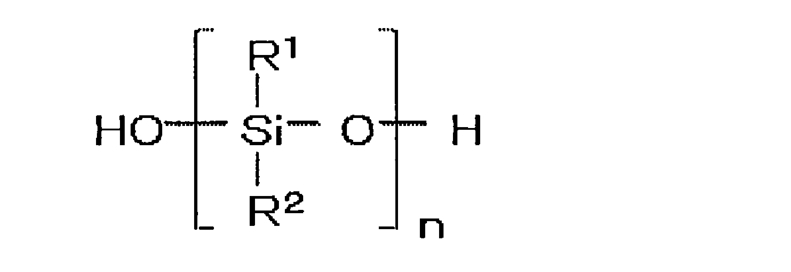
末端シラノール変性ポリオルガノシロキサンの30℃における粘度は、1~500mPa・s、好ましくは5~100mPa・s、さらに好ましくは10~50mPa・sである。また、末端シラノール変性ポリオルガノシロキサンの質量平均分子量(Mw)は、好適には、500~3000、より好ましくは700~2000、さらに好ましくは900~1200である。
(B)シリコンアルコキシド
シリコンアルコキシドとしては、炭素数1~4の低級アルキル基を有するトリまたはテトラアルコキシシランの1種あるいは2種以上の混合物が挙げられる。これらの具体例としては、トリメトキシシラン、テトラメトキシシラン、トリエトキシシラン、テトラエトキシシラン、テトラプロポキシシラン、テトラブトキシシラン等が挙げられる。また、これらのオリゴマーも使用することが出来る。シリコンアルコキシドの特に好ましい例は、テトラメトキシシランあるいはテトラエトキシシランである。
シリコンアルコキシドとしては、炭素数1~4の低級アルキル基を有するトリまたはテトラアルコキシシランの1種あるいは2種以上の混合物が挙げられる。これらの具体例としては、トリメトキシシラン、テトラメトキシシラン、トリエトキシシラン、テトラエトキシシラン、テトラプロポキシシラン、テトラブトキシシラン等が挙げられる。また、これらのオリゴマーも使用することが出来る。シリコンアルコキシドの特に好ましい例は、テトラメトキシシランあるいはテトラエトキシシランである。
シリコンアルコキシドは、1モルのポリオルガノシロキサンに対して、0.5~4モル、さらには0.7~2モルの範囲で組成物中に含まれるのが好ましい。シリコンアルコキシドは、ポリオルガノシロキサンの分子を架橋する架橋剤として機能する。このため、シリコンアルコキシドが少なすぎるとポリオルガノシロキサンの架橋が不十分となり、多すぎると、硬化の初期に、両末端がアルコキシドによって変性したポリオルガノシロキサンが余剰に存在し、硬化反応が遅くなる傾向がある。シリコンアルコキシドは、1モルのポリオルガノシロキサンと同モル存在するのが、より好ましい。
(C)チタニウムアルコキシド
チタニウムアルコキシドとしては、チタニウムテトラエトキシド、チタニウムテトラプロポキシド、チタニウムテトライソプロポキシド、チタニウムテトラブトキシド、チタニウムテトライソブトキシド、チタニウムテトライソプロペニルオキシドなどの1種あるいは2種以上の混合物が挙げられる。また、これらのオリゴマーも使用することが出来る。チタニウムアルコキシドの好ましい例は、チタニウムテトラエトキシド、チタニウムテトライソプロポキシド、またはチタニウムテトラブトキシドであり、その中でもチタニウムテトラエトキシドが好ましい。
チタニウムアルコキシドとしては、チタニウムテトラエトキシド、チタニウムテトラプロポキシド、チタニウムテトライソプロポキシド、チタニウムテトラブトキシド、チタニウムテトライソブトキシド、チタニウムテトライソプロペニルオキシドなどの1種あるいは2種以上の混合物が挙げられる。また、これらのオリゴマーも使用することが出来る。チタニウムアルコキシドの好ましい例は、チタニウムテトラエトキシド、チタニウムテトライソプロポキシド、またはチタニウムテトラブトキシドであり、その中でもチタニウムテトラエトキシドが好ましい。
チタニウムアルコキシドは、1モルのポリオルガノシロキサンに対して、0.01~0.5モル、好ましくは0.02~0.1モルの範囲で組成物中に含まれるのが好ましい。チタニウムアルコキシドが少なすぎると、硬化しにくくなり、多すぎると、硬くなり、弾性を失いやすい。
(D)ヒドロキシカルボン酸エステル
ヒドロキシカルボン酸エステルは、炭素数3~6のヒドロキシカルボン酸と炭素数1~20のアルコールとのエステル反応による生成物の1種あるいは2種以上の混合物である。ヒロキシカルボン酸としては、乳酸、グリセリン酸等のモノカルボン酸、リンゴ酸、酒石酸等のジカルボン酸、クエン酸等のトリカルボン酸を例示できる。アルコールとしては、メチルアルコール、エチルアルコール、n-プロピルアルコール、i-プロピルアルコール、n-ブチルアルコール、i-ブチルアルコール、ter-ブチルアルコール、ペンチルアルコール、ヘキシルアルコール、ヘプチルアルコール、オクチルアルコール、ノニルアルコール、デシルアルコール、ラウリルアルコール、ミリスチルアルコール、パルミチルアルコール、ステアリルアルコール等の脂肪族飽和アルコールを例示できる。
ヒドロキシカルボン酸エステルは、炭素数3~6のヒドロキシカルボン酸と炭素数1~20のアルコールとのエステル反応による生成物の1種あるいは2種以上の混合物である。ヒロキシカルボン酸としては、乳酸、グリセリン酸等のモノカルボン酸、リンゴ酸、酒石酸等のジカルボン酸、クエン酸等のトリカルボン酸を例示できる。アルコールとしては、メチルアルコール、エチルアルコール、n-プロピルアルコール、i-プロピルアルコール、n-ブチルアルコール、i-ブチルアルコール、ter-ブチルアルコール、ペンチルアルコール、ヘキシルアルコール、ヘプチルアルコール、オクチルアルコール、ノニルアルコール、デシルアルコール、ラウリルアルコール、ミリスチルアルコール、パルミチルアルコール、ステアリルアルコール等の脂肪族飽和アルコールを例示できる。
上記のヒドロキシカルボン酸と上記アルコールとのエステル反応により生成されるヒドロキシカルボン酸エステルとしては、例えば、リンゴ酸エステル、クエン酸エステル、乳酸エステル、酒石酸エステル、グリコールモノエステル、グリセリンモノエステル、グリセリンジエステル、リシノール酸エステルを挙げることができる。特に、リンゴ酸エステル、クエン酸エステル、乳酸エステル、酒石酸エステルが好ましく、その中でもさらに、リンゴ酸エステルが好ましい。リンゴ酸エステルとしては、特に、リンゴ酸ジアルキルエステルが好ましい。リンゴ酸ジアルキルエステルとしては、例えば、リンゴ酸ジメチルエステル、リンゴ酸ジエチルエステル、リンゴ酸ジプロピルエステル、リンゴ酸ジブチルエステル、リンゴ酸ジヘキシルエステル、アセチルリンゴ酸ジオクチルエステル、リンゴ酸モノエチルモノオクチルエステルなどが挙げられる。その中でも、特に、リンゴ酸ジエチルエステルおよびリンゴ酸ジブチルエステルが好ましい。
ヒドロキシカルボン酸エステルは、1モルのポリオルガノシロキサンに対して0.01~0.5モルの範囲で組成物中に含まれるのが好ましく、特に0.02~0.1モルの範囲で組成物中に含まれるのが好ましい。さらには、ヒドロキシカルボン酸エステルは、チタニウムアルコキシドと等モルで、好ましくは0.01~0.5モルの範囲、より好ましくは0.02~0.1モルの範囲で、組成物中に含まれる。
次に、実施の形態に係るポリオルガノシロキサン組成物およびその硬化体の製造方法について説明する。
1.ポリオルガノシロキサン組成物の製造方法
1分子中の少なくとも一方の末端がシラノール変性したポリオルガノシロキサンと、そのポリオルガノシロキサン1モルに対して0.5~4モルのシリコンアルコキシドと、上記ポリオルガノシロキサン1モルに対して0.01~0.5モルのチタニウムアルコキシドと、上記ポリオルガノシロキサン1モルに対して0.01~0.5モルのヒドロキシカルボン酸エステルとを容器内に投入し、20~120℃、好ましくは25~80℃、より好ましくは30~50℃の温度にて攪拌する。攪拌の雰囲気は、密閉雰囲気あるいは開放雰囲気のいずれかを選択することができる。また、開放雰囲気にて攪拌を行う場合には、窒素ガスあるいはアルゴンガス等を流して行うのが好ましい。攪拌中、FT-IRの測定により、Si-O-Ti結合に起因する920cm-1の吸収ピークとGPC測定でシリコンアルコキシドに起因するピークを確認し、これらのピークが消滅したことを確認し、攪拌を終了するのが好ましい。PDMSのシラノール基とシリコンアルコキシドのアルコキシ基が反応したのを確認するためである。
1分子中の少なくとも一方の末端がシラノール変性したポリオルガノシロキサンと、そのポリオルガノシロキサン1モルに対して0.5~4モルのシリコンアルコキシドと、上記ポリオルガノシロキサン1モルに対して0.01~0.5モルのチタニウムアルコキシドと、上記ポリオルガノシロキサン1モルに対して0.01~0.5モルのヒドロキシカルボン酸エステルとを容器内に投入し、20~120℃、好ましくは25~80℃、より好ましくは30~50℃の温度にて攪拌する。攪拌の雰囲気は、密閉雰囲気あるいは開放雰囲気のいずれかを選択することができる。また、開放雰囲気にて攪拌を行う場合には、窒素ガスあるいはアルゴンガス等を流して行うのが好ましい。攪拌中、FT-IRの測定により、Si-O-Ti結合に起因する920cm-1の吸収ピークとGPC測定でシリコンアルコキシドに起因するピークを確認し、これらのピークが消滅したことを確認し、攪拌を終了するのが好ましい。PDMSのシラノール基とシリコンアルコキシドのアルコキシ基が反応したのを確認するためである。
ポリオルガノシロキサンと、シリコンアルコキシドと、チタニウムアルコキシドと、ヒドロキシカルボン酸エステルとを混合する際、ポリオルガノシロキサンとシリコンアルコキシドを混合した混合液1と、チタニウムアルコキシドとヒドロキシカルボン酸エステルとを別に混合した混合液2とを混合するのが好ましい。ポリオルガノシロキサンとシリコンアルコキシドの溶液の中で、チタンアルコキシドにヒドロキシカルボン酸エステルを配位させるよりも、混合液1と混合液2とをそれぞれ分けて混合した方が、反応が均一になると考えたからである。その場合、混合液1は、25~60℃、好ましくは30~50℃、より好ましくは35~45℃の温度で攪拌して作製する。攪拌する環境は、不活性ガス雰囲気下であるのが好ましい。一方、混合液2は、15~40℃、好ましくは20~35℃、より好ましくは25~30℃の温度範囲で攪拌して作製する。攪拌する環境は、不活性ガス雰囲気下であるのが好ましい。
2.ポリオルガノシロキサン組成物の硬化体の製造方法
例えば、上記の方法にて得られた実施の形態に係るポリオルガノシロキサン組成物を、15~45℃、好ましくは20~30℃の温度にて、湿度50%±20%R.H.、好ましくは50%±10%の雰囲気下に保たれた環境下で静置することにより、ポリオルガノシロキサン組成物の硬化体が得られる。実施の形態に係るポリオルガノシロキサン組成物は、いわゆる室温でも硬化するという利点を有する。硬化までの静置時間は、0.1時間以上、特に100時間以上、さらには150時間以上、さらには200時間以上が好ましい。
例えば、上記の方法にて得られた実施の形態に係るポリオルガノシロキサン組成物を、15~45℃、好ましくは20~30℃の温度にて、湿度50%±20%R.H.、好ましくは50%±10%の雰囲気下に保たれた環境下で静置することにより、ポリオルガノシロキサン組成物の硬化体が得られる。実施の形態に係るポリオルガノシロキサン組成物は、いわゆる室温でも硬化するという利点を有する。硬化までの静置時間は、0.1時間以上、特に100時間以上、さらには150時間以上、さらには200時間以上が好ましい。
<第二の実施の形態>
次に、本発明のポリオルガノシロキサン組成物およびその硬化体の第二の実施の形態について説明する。第一の実施の形態と共通する内容については、適宜、その説明を省略する。
次に、本発明のポリオルガノシロキサン組成物およびその硬化体の第二の実施の形態について説明する。第一の実施の形態と共通する内容については、適宜、その説明を省略する。
この実施の形態に係るポリオルガノシロキサン組成物は、
(A)1分子中の少なくとも一方の末端がシラノール変性したポリオルガノシロキサンと、
(B)上記ポリオルガノシロキサン1モルに対して0.5~30モルのシリコンアルコキシドと、
(C)上記ポリオルガノシロキサン1モルに対して0.01~2.0モルのチタニウムアルコキシドと、
(D)上記ポリオルガノシロキサン1モルに対して0.01~2.0モルのヒドロキシカルボン酸エステルと、を少なくとも含むゾル若しくはゲル状の組成物である。
また、この実施の形態に係るポリオルガノシロキサン組成物は、上記(A)~(D)に加えて、(E)ポリオルガノシロキサン組成物の全重量に対して2~30重量%を占める無機フィラーを含有するのがより好ましい。以下、当該組成物に含有され得る上記(A)、(B)、(C)、(D)および(E)について説明する。
(A)1分子中の少なくとも一方の末端がシラノール変性したポリオルガノシロキサンと、
(B)上記ポリオルガノシロキサン1モルに対して0.5~30モルのシリコンアルコキシドと、
(C)上記ポリオルガノシロキサン1モルに対して0.01~2.0モルのチタニウムアルコキシドと、
(D)上記ポリオルガノシロキサン1モルに対して0.01~2.0モルのヒドロキシカルボン酸エステルと、を少なくとも含むゾル若しくはゲル状の組成物である。
また、この実施の形態に係るポリオルガノシロキサン組成物は、上記(A)~(D)に加えて、(E)ポリオルガノシロキサン組成物の全重量に対して2~30重量%を占める無機フィラーを含有するのがより好ましい。以下、当該組成物に含有され得る上記(A)、(B)、(C)、(D)および(E)について説明する。
(A)末端シラノール変性ポリオルガノシロキサン
末端シラノール変性ポリオルガノシロキサンの質量平均分子量(Mw)は、好適には、500~100000、より好ましくは700~50000、さらに好ましくは900~40000である。その他については、第一の実施の形態と共通するので、説明を省略する。
末端シラノール変性ポリオルガノシロキサンの質量平均分子量(Mw)は、好適には、500~100000、より好ましくは700~50000、さらに好ましくは900~40000である。その他については、第一の実施の形態と共通するので、説明を省略する。
(B)シリコンアルコキシド
シリコンアルコキシドとしては、第一の実施の形態と同様、炭素数1~4の低級アルキル基を有するトリまたはテトラアルコキシシランが挙げられる。これらの具体例としては、メチルトリメトキシシラン、トリメトキシシラン、テトラメトキシシラン、トリエトキシシラン、テトラエトキシシラン、テトラプロポキシシラン、テトラブトキシシラン等が挙げられる。また、これらのオリゴマーも使用することが出来る。シリコンアルコキシドの特に好ましい例は、メチルトリメトキシシラン、テトラメトキシシランあるいはテトラエトキシシランである。
シリコンアルコキシドとしては、第一の実施の形態と同様、炭素数1~4の低級アルキル基を有するトリまたはテトラアルコキシシランが挙げられる。これらの具体例としては、メチルトリメトキシシラン、トリメトキシシラン、テトラメトキシシラン、トリエトキシシラン、テトラエトキシシラン、テトラプロポキシシラン、テトラブトキシシラン等が挙げられる。また、これらのオリゴマーも使用することが出来る。シリコンアルコキシドの特に好ましい例は、メチルトリメトキシシラン、テトラメトキシシランあるいはテトラエトキシシランである。
シリコンアルコキシドは、1モルのポリオルガノシロキサンに対して、0.5~30モルの範囲、さらには、末端シラノール変性ポリオルガノシロキサンのMwが10000以上である場合には1~25モルの範囲で組成物中に含まれるのが好ましい。特に、シリコンアルコキシドにメチルトリメトキシシランを用い、かつポリオルガノシロキサン組成物中に無機フィラーを含有する場合には、メチルトリメトキシシランは、1モルのポリオルガノシロキサンに対して5モル以上含める方が好ましい。一方、シリコンアルコキシドにテトラメトキシシランを用い、かつポリオルガノシロキサン組成物中に無機フィラーを含有する場合には、テトラメトキシシランは、1モルのポリオルガノシロキサンに対して20モル以下含める方が好ましい。
(C)チタニウムアルコキシド
チタニウムアルコキシドは、1モルのポリオルガノシロキサンに対して、0.01~2モル、好ましくは0.02~1モルの範囲で組成物中に含まれるのが好ましい。チタニウムアルコキシドに属する具体的なアルコキシドおよび好ましいアルコキシドは、第一の実施の形態にて説明したものと同様である。
チタニウムアルコキシドは、1モルのポリオルガノシロキサンに対して、0.01~2モル、好ましくは0.02~1モルの範囲で組成物中に含まれるのが好ましい。チタニウムアルコキシドに属する具体的なアルコキシドおよび好ましいアルコキシドは、第一の実施の形態にて説明したものと同様である。
(D)ヒドロキシカルボン酸エステル
ヒドロキシカルボン酸エステルは、1モルのポリオルガノシロキサンに対して、0.01~2モル、好ましくは0.02~1モルの範囲で組成物中に含まれるのが好ましい。特に、チタニウムアルコキシドと同モルにすると、より好ましい。ヒドロキシカルボン酸エステルに属する具体的なエステルおよび好ましいエステルは、第一の実施の形態にて説明したものと同様である。
ヒドロキシカルボン酸エステルは、1モルのポリオルガノシロキサンに対して、0.01~2モル、好ましくは0.02~1モルの範囲で組成物中に含まれるのが好ましい。特に、チタニウムアルコキシドと同モルにすると、より好ましい。ヒドロキシカルボン酸エステルに属する具体的なエステルおよび好ましいエステルは、第一の実施の形態にて説明したものと同様である。
(E)無機フィラー
無機フィラーとしては、シリカ、酸化チタン、アルミナ、ジルコニア等の無機酸化物の粒子状、板状あるいは繊維状のフィラーを例示することができる。特に、粒子径が小さく、かつポリオルガノシロキサン組成物との相性の良いシリカが好ましい。無機フィラーの含有量は、無機フィラーも含めたポリオルガノシロキサン組成物の全重量に対して2~30重量%、より好ましくは5~20重量%、さらに好ましくは7~15重量%である。
無機フィラーとしては、シリカ、酸化チタン、アルミナ、ジルコニア等の無機酸化物の粒子状、板状あるいは繊維状のフィラーを例示することができる。特に、粒子径が小さく、かつポリオルガノシロキサン組成物との相性の良いシリカが好ましい。無機フィラーの含有量は、無機フィラーも含めたポリオルガノシロキサン組成物の全重量に対して2~30重量%、より好ましくは5~20重量%、さらに好ましくは7~15重量%である。
次に、第二の実施の形態に係るポリオルガノシロキサン組成物およびその硬化体の製造方法について説明する。
1.ポリオルガノシロキサン組成物の製造方法
1分子中の少なくとも一方の末端がシラノール変性したポリオルガノシロキサンと、そのポリオルガノシロキサン1モルに対して0.5~30モルのシリコンアルコキシドと、上記ポリオルガノシロキサン1モルに対して0.01~2モルのチタニウムアルコキシドと、上記ポリオルガノシロキサン1モルに対して0.01~2モルのヒドロキシカルボン酸エステルと、ポリオルガノシロキサン組成物の全重量に対して2~30重量%を占める無機フィラーとを容器内に投入し、20~120℃、好ましくは25~80℃、より好ましくは30~50℃の温度にて攪拌する。攪拌の雰囲気は、密閉雰囲気あるいは開放雰囲気のいずれかを選択することができる。また、開放雰囲気にて攪拌を行う場合には、窒素ガスあるいはアルゴンガス等を流して行うのが好ましい。攪拌中、FT-IRの測定により、Si-O-Ti結合に起因する920cm-1の吸収ピークとGPC測定でシリコンアルコキシドに起因するピークを確認し、これらのピークが消滅したことを確認し、攪拌を終了するのが好ましい。PDMSのシラノール基とシリコンアルコキシドのアルコキシ基が反応したのを確認するためである。
1分子中の少なくとも一方の末端がシラノール変性したポリオルガノシロキサンと、そのポリオルガノシロキサン1モルに対して0.5~30モルのシリコンアルコキシドと、上記ポリオルガノシロキサン1モルに対して0.01~2モルのチタニウムアルコキシドと、上記ポリオルガノシロキサン1モルに対して0.01~2モルのヒドロキシカルボン酸エステルと、ポリオルガノシロキサン組成物の全重量に対して2~30重量%を占める無機フィラーとを容器内に投入し、20~120℃、好ましくは25~80℃、より好ましくは30~50℃の温度にて攪拌する。攪拌の雰囲気は、密閉雰囲気あるいは開放雰囲気のいずれかを選択することができる。また、開放雰囲気にて攪拌を行う場合には、窒素ガスあるいはアルゴンガス等を流して行うのが好ましい。攪拌中、FT-IRの測定により、Si-O-Ti結合に起因する920cm-1の吸収ピークとGPC測定でシリコンアルコキシドに起因するピークを確認し、これらのピークが消滅したことを確認し、攪拌を終了するのが好ましい。PDMSのシラノール基とシリコンアルコキシドのアルコキシ基が反応したのを確認するためである。
ポリオルガノシロキサンと、シリコンアルコキシドと、チタニウムアルコキシドと、ヒドロキシカルボン酸エステルとを混合する際、ポリオルガノシロキサンとシリコンアルコキシドを混合した混合液1と、チタニウムアルコキシドとヒドロキシカルボン酸エステルとを別に混合した混合液2とを用意して、両者を混合するのが好ましい。無機フィラーを加える場合には、混合液1、混合液2のいずれか、あるいは両方に当該無機フィラーを添加しておくのが好ましい。このように複数の混合液を用意するのは、ポリオルガノシロキサンとシリコンアルコキシドの溶液の中で、チタンアルコキシドにヒドロキシカルボン酸エステルを配位させるよりも、混合液1と混合液2とをそれぞれ分けて混合した方が、反応が均一になると考えられるからである。その場合、混合液1は、25~60℃、好ましくは30~50℃、より好ましくは35~45℃の温度で攪拌して作製する。攪拌する環境は、不活性ガス雰囲気下であるのが好ましい。一方、混合液2は、15~40℃、好ましくは20~35℃、より好ましくは25~30℃の温度範囲で攪拌して作製する。攪拌する環境は、不活性ガス雰囲気下であるのが好ましい。
2.ポリオルガノシロキサン組成物の硬化体の製造方法
例えば、上記の方法にて得られた第二の実施の形態に係るポリオルガノシロキサン組成物を、15~45℃、好ましくは20~30℃の温度にて、湿度50%±20%R.H.、好ましくは50%±10%の雰囲気下に保たれた環境下で静置することにより、ポリオルガノシロキサン組成物の硬化体が得られる。第二の実施の形態に係るポリオルガノシロキサン組成物は、いわゆる室温でも硬化するという利点を有する。硬化までの静置時間は、0.1時間以上、特に100時間以上、さらには150時間以上、さらには200時間以上が好ましい。
例えば、上記の方法にて得られた第二の実施の形態に係るポリオルガノシロキサン組成物を、15~45℃、好ましくは20~30℃の温度にて、湿度50%±20%R.H.、好ましくは50%±10%の雰囲気下に保たれた環境下で静置することにより、ポリオルガノシロキサン組成物の硬化体が得られる。第二の実施の形態に係るポリオルガノシロキサン組成物は、いわゆる室温でも硬化するという利点を有する。硬化までの静置時間は、0.1時間以上、特に100時間以上、さらには150時間以上、さらには200時間以上が好ましい。
また、第二の実施の形態に係るポリオルガノシロキサン組成物を、室温以上、例えば、50~300℃で0.1時間以上静置して硬化させることもできる。硬化温度は、80~250℃の範囲が特に好ましい。また、硬化までの静置時間は、0.1時間以上、特に100時間以上、さらには150時間以上、さらには200時間以上が好ましい。
以下、本発明の実施例について説明する。
I.ポリオルガノシロキサン-シリコンアルコキシド-チタニウムアルコキシド-ヒドロキシカルボン酸エステル系
<実施例1>
1.DL-リンゴ酸ジエチルエステルを用いた硬化体の特性評価
(1)硬化体の作製方法
乾燥窒素ガスを流して空気を乾燥窒素ガスで置換した状態のグローブボックス内にて、蓋付きガラス容器(容量:200mlのセパラブルフラスコ)中に、30℃における粘度が34mPa・sの両末端シラノール変性ポリジメチルシロキサン(Polydimethylsiloxane: PDMS、信越化学工業株式会社製、X-21-5841、Mw=1000、以後、単に、PDMSという)50g、テトラエトキシシラン(Tetraethoxysilane: TEOS)10.417gを順に入れた。次に、グローブボックス内でチタニウムテトラエトキシド(Tetraethoxytitanium: TTE、メルク社製)、DL-リンゴ酸ジエチルエステル(DL-malicacid diethyl ester: MA、東京化成工業株式会社製)を同モルでスクリュー管瓶の中に入れ、25℃で30分間撹拌したものを1.045g入れ、該ガラス容器の蓋を閉めた(モル比にて、PDMS:TEOS:TTE:MA=1:1:0.05:0.05)。この内容物を「TTE-MA系溶液」とした。次に、グローブボックス外に蓋を閉めた状態のガラス容器を取り出した。TTE-MA系溶液は、密封雰囲気下において、ガラス容器に乾燥窒素ガスを流しながら、プロペラ付きの攪拌棒を挿入し、40℃に保持されたオイルバスに浸し、撹拌を開始した。その後、FT-IR測定でSi-O-Ti結合に起因する920cm-1の吸収ピークとGPC測定でTEOSに起因するピークを確認しながら撹拌を行い、Si-O-Ti結合とTEOSに起因するピークが消滅したことを96時間後に確認した。その後シャーレに展開し、温度25℃、湿度50%±10%R.H.の雰囲気下に保たれたボックス内で168時間放置し、硬化体を得た。この硬化体を「TTE-MA系硬化体」とした。
<実施例1>
1.DL-リンゴ酸ジエチルエステルを用いた硬化体の特性評価
(1)硬化体の作製方法
乾燥窒素ガスを流して空気を乾燥窒素ガスで置換した状態のグローブボックス内にて、蓋付きガラス容器(容量:200mlのセパラブルフラスコ)中に、30℃における粘度が34mPa・sの両末端シラノール変性ポリジメチルシロキサン(Polydimethylsiloxane: PDMS、信越化学工業株式会社製、X-21-5841、Mw=1000、以後、単に、PDMSという)50g、テトラエトキシシラン(Tetraethoxysilane: TEOS)10.417gを順に入れた。次に、グローブボックス内でチタニウムテトラエトキシド(Tetraethoxytitanium: TTE、メルク社製)、DL-リンゴ酸ジエチルエステル(DL-malicacid diethyl ester: MA、東京化成工業株式会社製)を同モルでスクリュー管瓶の中に入れ、25℃で30分間撹拌したものを1.045g入れ、該ガラス容器の蓋を閉めた(モル比にて、PDMS:TEOS:TTE:MA=1:1:0.05:0.05)。この内容物を「TTE-MA系溶液」とした。次に、グローブボックス外に蓋を閉めた状態のガラス容器を取り出した。TTE-MA系溶液は、密封雰囲気下において、ガラス容器に乾燥窒素ガスを流しながら、プロペラ付きの攪拌棒を挿入し、40℃に保持されたオイルバスに浸し、撹拌を開始した。その後、FT-IR測定でSi-O-Ti結合に起因する920cm-1の吸収ピークとGPC測定でTEOSに起因するピークを確認しながら撹拌を行い、Si-O-Ti結合とTEOSに起因するピークが消滅したことを96時間後に確認した。その後シャーレに展開し、温度25℃、湿度50%±10%R.H.の雰囲気下に保たれたボックス内で168時間放置し、硬化体を得た。この硬化体を「TTE-MA系硬化体」とした。
比較のため、PDMS、TEOSおよびTTEを混合した溶液(以後、「TTE系溶液」という)を硬化させた硬化体(TTE系硬化体)と、PDMA、TEOSおよびTTEにアセト酢酸エチル(EAcAc)を配位させたものを混合した溶液(以後、「TTE-EAcAc系溶液」という)を硬化させた硬化体(TTE-EAcAc系硬化体)も作製した。TTE系硬化体を作製するため、窒素置換されたグローブボックス内で、蓋付きガラス容器(容量:200ml)に、PDMS50g、TEOS10.417g、TTE0.570gを順に入れ、該ガラス容器の蓋を閉めた(モル比にて、PDMS:TEOS:TTE=1:1:0.05)。TTE-EAcAc系硬化体の作製も同様に、蓋付きガラス容器(容量:200ml)に、PDMS50g、TEOS10.417g、TTE0.570g、EAcAc0.325gを順に入れ、該ガラス容器の蓋を閉めた(モル比にて、PDMS:TEOS:TTE:EAcAc=1:1:0.05:0.05)。次に、グローブボックス外に蓋を閉めた状態の各ガラス容器を取り出した。その後、TTE系溶液およびTTE-EAcAc系溶液は、前述のTTE-MA系溶液と同様の処理を行い、Si-O-Ti結合とTEOSに起因するピークが消滅したことを、TTE系溶液では120時間後に、TTE-EAcAc系溶液では96時間後にそれぞれ確認した。その後、各溶液をそれぞれシャーレに展開し、温度25℃、湿度50%±10%R.H.の雰囲気下に保たれたボックス内で168時間放置し、TTE系硬化体およびTTE-EAcAc系硬化体を得た。
(2)引張特性評価
上記の方法で得られた各種シート状硬化体をダンベルで打ち抜き、引張試験用の試験片を作製し、オートグラフ(AGS-J:SHIMADZU)を用いてJISK6251に従って引張試験を行った。引張速度は500mm/minとした。以後、引張特性評価時の引張速度は、全て同一速度とした。
上記の方法で得られた各種シート状硬化体をダンベルで打ち抜き、引張試験用の試験片を作製し、オートグラフ(AGS-J:SHIMADZU)を用いてJISK6251に従って引張試験を行った。引張速度は500mm/minとした。以後、引張特性評価時の引張速度は、全て同一速度とした。
表1に、TTE-MA系硬化体、TTE系硬化体およびTTE-EAcAc系硬化体の各引張特性の評価結果を示す。なお、以後、実施例1から実施例4において、破断点伸び(%)は、元の長さに対する伸びた分の比率で示す。

表1に示すように、TTE-MA系硬化体は、TTE系硬化体およびTTE-EAcAc系硬化体に比べて、弾性率および破断点強度が優れていることがわかった。これは、TTE-MA系硬化体が他の硬化体に比べて、架橋の程度が優れていることを示唆している。
2.各種ヒドロキシカルボン酸エステルを用いた硬化体の特性評価
(1)各硬化体の作製方法
(1-1)DL-リンゴ酸ジブチルエステル系
乾燥窒素ガスを流した状態のグローブボックス内にて、蓋付きガラス容器(容量:200ml)中に、PDMS50g、TEOS10.417gを順に入れた。次に、グローブボックス内でTTEとDL-リンゴ酸ジブチルエステル(DL-malicacid dibutyl ester: MADb、東京化成工業株式会社製)を同モルでスクリュー管瓶の中に入れ、25℃で30分間撹拌したものを1.186g入れ、該ガラス容器の蓋を閉めた(モル比にて、PDMS:TEOS:TTE:MADb=1:1:0.05:0.05)。この内容物を「TTE-MADb系溶液」とした。次に、グローブボックス外に蓋を閉めた状態のガラス容器を取り出した。その後、TTE-MADb系溶液は、前述のTTE-MA系溶液と同様の処理を行い、Si-O-Ti結合とTEOSに起因するピークが消滅したことを96時間後に確認した。その後、TTE-MADb系溶液をシャーレに展開し、温度25℃、湿度50%±10%R.H.の雰囲気下に保たれたボックス内で168時間(以後、「7日間」という)および336時間(以後、「14日間」という)の2通りで放置し、各硬化体(TTE-MADb系硬化体)を得た。
(1)各硬化体の作製方法
(1-1)DL-リンゴ酸ジブチルエステル系
乾燥窒素ガスを流した状態のグローブボックス内にて、蓋付きガラス容器(容量:200ml)中に、PDMS50g、TEOS10.417gを順に入れた。次に、グローブボックス内でTTEとDL-リンゴ酸ジブチルエステル(DL-malicacid dibutyl ester: MADb、東京化成工業株式会社製)を同モルでスクリュー管瓶の中に入れ、25℃で30分間撹拌したものを1.186g入れ、該ガラス容器の蓋を閉めた(モル比にて、PDMS:TEOS:TTE:MADb=1:1:0.05:0.05)。この内容物を「TTE-MADb系溶液」とした。次に、グローブボックス外に蓋を閉めた状態のガラス容器を取り出した。その後、TTE-MADb系溶液は、前述のTTE-MA系溶液と同様の処理を行い、Si-O-Ti結合とTEOSに起因するピークが消滅したことを96時間後に確認した。その後、TTE-MADb系溶液をシャーレに展開し、温度25℃、湿度50%±10%R.H.の雰囲気下に保たれたボックス内で168時間(以後、「7日間」という)および336時間(以後、「14日間」という)の2通りで放置し、各硬化体(TTE-MADb系硬化体)を得た。
(1-2)クエン酸トリブチル系
DL-リンゴ酸ジブチルエステル系と同様の方法にて、TTEとクエン酸トリブチル(Tributyl citrate: CAtB、東京化成工業株式会社製)を同モルでスクリュー管瓶の中に入れ、25℃で30分間撹拌したものを1.472g入れ、該ガラス容器の蓋を閉めた(モル比にて、PDMS:TEOS:TTE:CAtB=1:1:0.05:0.05)。この内容物を「TTE-CAtB系溶液」とした。その後の処理も、DL-リンゴ酸ジブチルエステル系と同様とし、各硬化体(TTE-CAtB系硬化体)を得た。
DL-リンゴ酸ジブチルエステル系と同様の方法にて、TTEとクエン酸トリブチル(Tributyl citrate: CAtB、東京化成工業株式会社製)を同モルでスクリュー管瓶の中に入れ、25℃で30分間撹拌したものを1.472g入れ、該ガラス容器の蓋を閉めた(モル比にて、PDMS:TEOS:TTE:CAtB=1:1:0.05:0.05)。この内容物を「TTE-CAtB系溶液」とした。その後の処理も、DL-リンゴ酸ジブチルエステル系と同様とし、各硬化体(TTE-CAtB系硬化体)を得た。
(1-3)クエン酸トリエチル系
DL-リンゴ酸ジブチルエステル系と同様の方法にて、TTEとクエン酸トリエチル(Triethyl citrate: CAtE、東京化成工業株式会社製)を同モルでスクリュー管瓶の中に入れ、25℃で30分間撹拌したものを1.261g入れ、該ガラス容器の蓋を閉めた(モル比にて、PDMS:TEOS:TTE:CAtE=1:1:0.05:0.05)。この内容物を「TTE-CAtE系溶液」とした。その後の処理も、DL-リンゴ酸ジブチルエステル系と同様とし、各硬化体(TTE-CAtE系硬化体)を得た。
DL-リンゴ酸ジブチルエステル系と同様の方法にて、TTEとクエン酸トリエチル(Triethyl citrate: CAtE、東京化成工業株式会社製)を同モルでスクリュー管瓶の中に入れ、25℃で30分間撹拌したものを1.261g入れ、該ガラス容器の蓋を閉めた(モル比にて、PDMS:TEOS:TTE:CAtE=1:1:0.05:0.05)。この内容物を「TTE-CAtE系溶液」とした。その後の処理も、DL-リンゴ酸ジブチルエステル系と同様とし、各硬化体(TTE-CAtE系硬化体)を得た。
(1-4)乳酸エチル系
DL-リンゴ酸ジブチルエステル系と同様の方法にて、TTEと乳酸エチル(Ethyl lactate: EL、東京化成工業株式会社製)を同モルでスクリュー管瓶の中に入れ、25℃で30分間撹拌したものを0.868g入れ、該ガラス容器の蓋を閉めた(モル比にて、PDMS:TEOS:TTE:EL=1:1:0.05:0.05)。この内容物を「TTE-EL系溶液」とした。その後の処理も、DL-リンゴ酸ジブチルエステル系と同様とし、各硬化体(TTE-EL系硬化体)を得た。
DL-リンゴ酸ジブチルエステル系と同様の方法にて、TTEと乳酸エチル(Ethyl lactate: EL、東京化成工業株式会社製)を同モルでスクリュー管瓶の中に入れ、25℃で30分間撹拌したものを0.868g入れ、該ガラス容器の蓋を閉めた(モル比にて、PDMS:TEOS:TTE:EL=1:1:0.05:0.05)。この内容物を「TTE-EL系溶液」とした。その後の処理も、DL-リンゴ酸ジブチルエステル系と同様とし、各硬化体(TTE-EL系硬化体)を得た。
(1-5)酒石酸エチル系
DL-リンゴ酸ジブチルエステル系と同様の方法にて、TTEと酒石酸エチル(L-(+)-diethyl tartarate: TAdEL、東京化成工業株式会社製)を同モルでスクリュー管瓶の中に入れ、25℃で30分間撹拌したものを1.086g入れ、該ガラス容器の蓋を閉めた(モル比にて、PDMS:TEOS:TTE:TAdE=1:1:0.05:0.05)。この内容物を「TTE-TAdE系溶液」とした。その後の処理も、DL-リンゴ酸ジブチルエステル系と同様とし、各硬化体(TTE-TAdE系硬化体)を得た。
DL-リンゴ酸ジブチルエステル系と同様の方法にて、TTEと酒石酸エチル(L-(+)-diethyl tartarate: TAdEL、東京化成工業株式会社製)を同モルでスクリュー管瓶の中に入れ、25℃で30分間撹拌したものを1.086g入れ、該ガラス容器の蓋を閉めた(モル比にて、PDMS:TEOS:TTE:TAdE=1:1:0.05:0.05)。この内容物を「TTE-TAdE系溶液」とした。その後の処理も、DL-リンゴ酸ジブチルエステル系と同様とし、各硬化体(TTE-TAdE系硬化体)を得た。
(2)引張特性評価
試験片の作製および引張特性評価は、前述と同様の方法にて行った。
試験片の作製および引張特性評価は、前述と同様の方法にて行った。
表2に、各溶液を7日間放置する条件にて硬化させたTTE-MA系硬化体、TTE-MADb系硬化体、TTE-CAtB系硬化体、TTE-CAtE系硬化体、TTE-EL系硬化体およびTTE-TAdE系硬化体の各引張特性の評価結果を示す。表中の硬化体に続くカッコ内の数字は、硬化時の放置日数を示す。以後の表でも同様とする。
表3に、各溶液を14日間放置する条件にて硬化させたTTE-MADb系硬化体、TTE-CAtB系硬化体、TTE-CAtE系硬化体、TTE-EL系硬化体およびTTE-TAdE系硬化体の各引張特性の評価結果を示す。

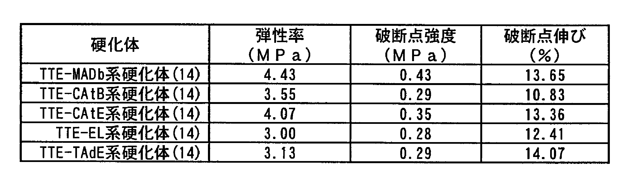
表1と表2を比較すると明らかなように、ヒドロキシカルボン酸エステルを加えて作製した硬化体は、全て、ヒドロキシカルボン酸エステルを加えずに作製した硬化体よりも大きな破断点強度および弾性率を有していた。また、表2に示すように、ヒドロキシカルボン酸エステルとしてDL-リンゴ酸ジエチルエステルあるいはDL-リンゴ酸ジブチルエステルを用いて作製した硬化体(TTE-MA系硬化体(7)およびTTE-MADb系硬化体(7))は、他種のヒドロキシカルボン酸エステルを用いて作製した硬化体よりも大きな破断点強度および弾性率を有していた。また、表2と表3を比較すると明らかなように、各溶液を14日放置して作製した硬化体は、7日放置したものと比べて同等以上の破断点強度および弾性率を有していた。このことは、硬化体作製時に長時間をかける方が硬化体の引張特性を向上できることを示している。
<実施例2>
1.TTEとMAの添加量を変化させた各硬化体の特性評価
(1)TEOS系
(1-1)硬化体の作製方法
乾燥窒素ガスを流した状態のグローブボックス内にて、蓋付きガラス容器(容量:200ml)中に、PDMS50g、TEOS10.417gを順に入れた。次に、グローブボックス内でTTEとMAを同モルでスクリュー管瓶の中に入れ、25℃で30分間撹拌したものを0.523g入れ、該ガラス容器の蓋を閉めた(モル比にて、PDMS:TEOS:TTE:MA=1:1:0.025:0.025)。この内容物を「TEOS-TTE-MA0.025系溶液」とした。同様の手順にて、TTEとMAを同モルでスクリュー管瓶の中に入れ、25℃で30分間撹拌したものを1.045g入れ、該ガラス容器の蓋を閉めた(モル比にて、PDMS:TEOS:TTE:MA=1:1:0.05:0.05)。この内容物を「TEOS-TTE-MA0.05系溶液」とした。また、同様の手順にて、TTEとMAを同モルでスクリュー管瓶の中に入れ、25℃で30分間撹拌したものを2.091g入れ、該ガラス容器の蓋を閉めた(モル比にて、PDMS:TEOS:TTE:MA=1:1:0.1:0.1)。この内容物を「TEOS-TTE-MA0.1系溶液」とした。次に、グローブボックス外に蓋を閉めた状態の各ガラス容器を取り出した。上記3種のTEOS-TTE-MA系溶液は、密封雰囲気下において、ガラス容器に乾燥窒素ガスを流しながら、プロペラ付きの攪拌棒を挿入し、40℃に保持されたオイルバスに浸し、撹拌を開始した。その後、FT-IR測定でSi-O-Ti結合に起因する920cm-1の吸収ピークとGPC測定でTEOSに起因するピークを確認しながら撹拌を行い、Si-O-Ti結合とTEOSに起因するピークが消滅したことをTEOS-TTE-MA0.025系溶液では216時間後に、TEOS-TTE-MA0.05系溶液では96時間後に、TEOS-TTE-MA0.1系溶液では24時間後に、それぞれ確認した。その後シャーレに展開し、温度25℃、湿度50%±10%R.H.の雰囲気下に保たれたボックス内で7日間および14日間の2通りで放置し、各硬化体を得た(TEOS-TTE-MA0.025系硬化体、TEOS-TTE-MA0.05系硬化体、TEOS-TTE-MA0.1系硬化体)。
1.TTEとMAの添加量を変化させた各硬化体の特性評価
(1)TEOS系
(1-1)硬化体の作製方法
乾燥窒素ガスを流した状態のグローブボックス内にて、蓋付きガラス容器(容量:200ml)中に、PDMS50g、TEOS10.417gを順に入れた。次に、グローブボックス内でTTEとMAを同モルでスクリュー管瓶の中に入れ、25℃で30分間撹拌したものを0.523g入れ、該ガラス容器の蓋を閉めた(モル比にて、PDMS:TEOS:TTE:MA=1:1:0.025:0.025)。この内容物を「TEOS-TTE-MA0.025系溶液」とした。同様の手順にて、TTEとMAを同モルでスクリュー管瓶の中に入れ、25℃で30分間撹拌したものを1.045g入れ、該ガラス容器の蓋を閉めた(モル比にて、PDMS:TEOS:TTE:MA=1:1:0.05:0.05)。この内容物を「TEOS-TTE-MA0.05系溶液」とした。また、同様の手順にて、TTEとMAを同モルでスクリュー管瓶の中に入れ、25℃で30分間撹拌したものを2.091g入れ、該ガラス容器の蓋を閉めた(モル比にて、PDMS:TEOS:TTE:MA=1:1:0.1:0.1)。この内容物を「TEOS-TTE-MA0.1系溶液」とした。次に、グローブボックス外に蓋を閉めた状態の各ガラス容器を取り出した。上記3種のTEOS-TTE-MA系溶液は、密封雰囲気下において、ガラス容器に乾燥窒素ガスを流しながら、プロペラ付きの攪拌棒を挿入し、40℃に保持されたオイルバスに浸し、撹拌を開始した。その後、FT-IR測定でSi-O-Ti結合に起因する920cm-1の吸収ピークとGPC測定でTEOSに起因するピークを確認しながら撹拌を行い、Si-O-Ti結合とTEOSに起因するピークが消滅したことをTEOS-TTE-MA0.025系溶液では216時間後に、TEOS-TTE-MA0.05系溶液では96時間後に、TEOS-TTE-MA0.1系溶液では24時間後に、それぞれ確認した。その後シャーレに展開し、温度25℃、湿度50%±10%R.H.の雰囲気下に保たれたボックス内で7日間および14日間の2通りで放置し、各硬化体を得た(TEOS-TTE-MA0.025系硬化体、TEOS-TTE-MA0.05系硬化体、TEOS-TTE-MA0.1系硬化体)。
上記の各種TEOS-TTE-MA系硬化体との比較のため、MAを加えずに硬化させたTTE系硬化体も作製した。窒素置換されたグローブボックス内で、蓋付きガラス容器(容量:200ml)に、PDMS50g、TEOS10.417g、TTE0.285gを順に入れ、該ガラス容器の蓋を閉めた(モル比にて、PDMS:TEOS:TTE=1:1:0.025)。この内容物を「TEOS-TTE0.025系溶液」とした。上記と同様の作製方法で、TTEの量のみを変化させ、TTE0.570g、TTE1.140g、TTE2.280gを入れた溶液も作製した。これらの内容物を、それぞれ「TEOS-TTE0.05系溶液」、「TEOS-TTE0.1系溶液」、「TEOS-TTE0.2系溶液」とした。次に、グローブボックス外に蓋を閉めた状態の各ガラス容器を取り出した。その後、上記4種のTEOS-TTE系溶液は、前述の各種TEOS-TTE-MA系溶液と同様の処理を行い、Si-O-Ti結合とTEOSに起因するピークが消滅したことを、TEOS-TTE0.025系溶液では216時間後に、TEOS-TTE0.05系溶液では96時間後に、TEOS-TTE0.1系溶液では48時間後に、TEOS-TTE0.2系溶液では24時間後に、それぞれ確認した。その後、各種TEOS-TTE系溶液を各シャーレに展開し、温度25℃、湿度50%±10%R.H.の雰囲気下に保たれたボックス内で7日間および14日間の2通りで放置し、各硬化体(TEOS-TTE0.025系硬化体、TEOS-TTE0.05系硬化体、TEOS-TTE0.1系硬化体、TEOS-TTE0.2系硬化体)を得た。
(1-2)引張特性評価
試験片の作製および引張特性評価は、前述と同様の方法にて行った。
試験片の作製および引張特性評価は、前述と同様の方法にて行った。
図1は、TEOS-TTE-MA0.025系溶液、TEOS-TTE-MA0.05系溶液、TEOS-TTE-MA0.1系溶液を、それぞれ25℃、湿度50%±10%R.H.の雰囲気下に保たれたボックス内で、7日間および14日間放置して硬化させた各硬化体の引張特性を示すグラフである。(A)、(B)および(C)は、PDMSに対するMAのモル比(TTEも同じ)を横軸にとり、弾性率(MPa)、破断点強度(MPa)および破断点伸び(%)をそれぞれ縦軸にとったグラフである。各グラフ中、黒塗りは7日間放置の条件で作製した硬化体の特性を、白抜きは14日放置の条件で作製した硬化体の特性を示す。黒塗りおよび白抜きの各プロットは、この実施例における以後の図でも同様とする。
表4は、図1に示す各硬化体の特性を示す表である。
図2は、TEOS-TTE0.025系溶液、TEOS-TTE0.05系溶液、TEOS-TTE0.1系溶液、TEOS-TTE0.2系溶液をそれぞれ25℃、湿度50%±10%R.H.の雰囲気下に保たれたボックス内で、7日間および14日間放置して硬化させた各硬化体の引張特性を示すグラフである。(A)、(B)および(C)は、PDMSに対するTTEのモル比を横軸にとり、弾性率(MPa)、破断点強度(MPa)および破断点伸び(%)をそれぞれ縦軸にとったグラフである。
表5は、図2に示す各硬化体の特性を示す表である。
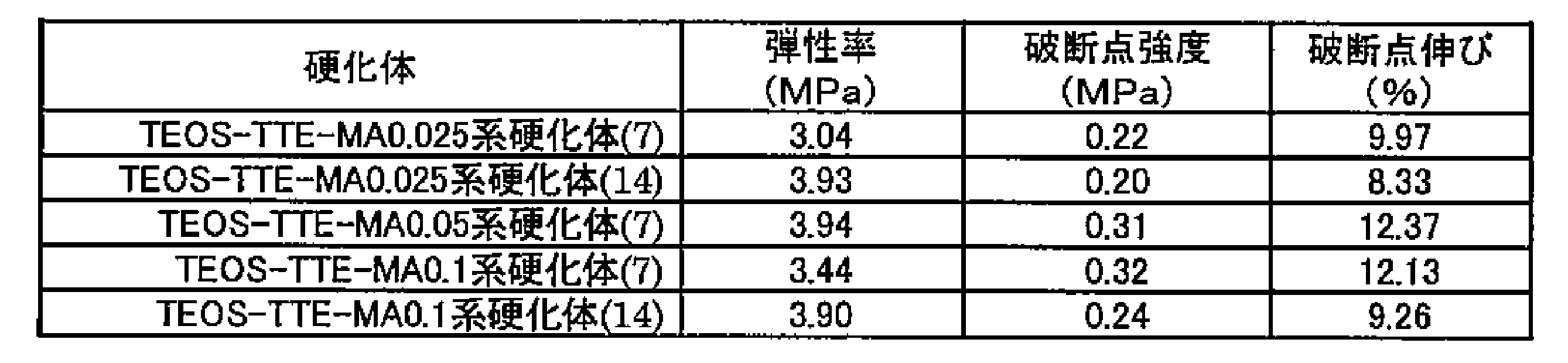
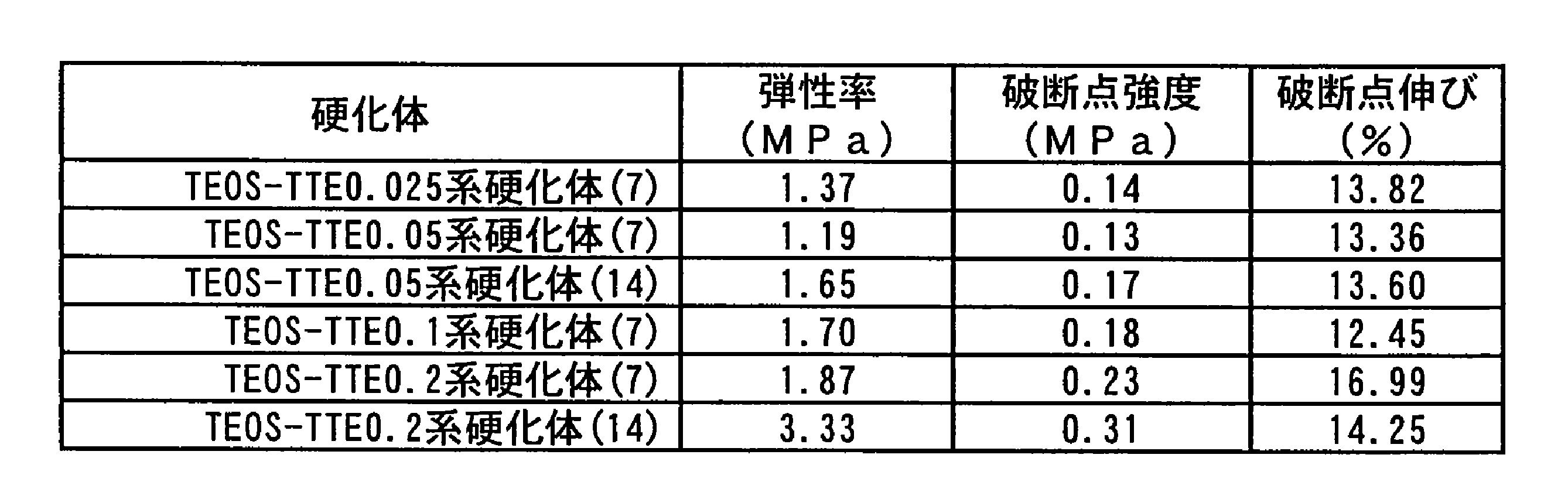
図1、図2、表4および表5に示すように、DL-リンゴ酸ジエチルエステルを加えて作製した硬化体はDL-リンゴ酸ジエチルエステルを加えずに作製した硬化体よりも大きな破断点強度および弾性率を有していることが確認できた。さらに、各溶液を14日放置して作製した硬化体は、7日放置したものと比べて大きな破断点強度および弾性率を有していることを確認できた。
(2)TMOS系
(2-1)硬化体の作製方法
乾燥窒素ガスを流した状態のグローブボックス内にて、蓋付きガラス容器(容量:200ml)中に、PDMS50g、テトラメトキシシラン(Tetramethoxysilane: TMOS、信越化学工業株式会社製、品番:KBM-04)7.612gを順に入れた。次に、グローブボックス内でTTEとMAを同モルでスクリュー管瓶の中に入れ、25℃で30分間撹拌したものを0.209g入れ、該ガラス容器の蓋を閉めた(モル比にて、PDMS:TMOS:TTE:MA=1:1:0.01:0.01)。この内容物を「TMOS-TTE-MA0.01系溶液」とした。同様の手順にて、TTEとMAを同モルでスクリュー管瓶の中に入れ、25℃で30分間撹拌したものを0.523g入れ、該ガラス容器の蓋を閉めた(モル比にて、PDMS:TMOS:TTE:MA=1:1:0.025:0.025)。この内容物を「TMOS-TTE-MA0.025系溶液」とした。また、同様の手順にて、TTEとMAを同モルでスクリュー管瓶の中に入れ、25℃で30分間撹拌したものを1.045g入れ、該ガラス容器の蓋を閉めた(モル比にて、PDMS:TMOS:TTE:MA=1:1:0.05:0.05)。この内容物を「TMOS-TTE-MA0.05系溶液」とした。次に、グローブボックス外に蓋を閉めた状態の各ガラス容器を取り出した。上記3種のTMOS-TTE-MA系溶液は、密封雰囲気下において、ガラス容器に乾燥窒素ガスを流しながら、プロペラ付きの攪拌棒を挿入し、40℃に保持されたオイルバスに浸し、撹拌を開始した。その後、FT-IR測定でSi-O-Ti結合に起因する920cm-1の吸収ピークとGPC測定でTMOSに起因するピークを確認しながら撹拌を行い、Si-O-Ti結合とTMOSに起因するピークが消滅したことをTMOS-TTE-MA0.01系溶液では96時間後に、TMOS-TTE-MA0.025系溶液およびTMOS-TTE-MA0.05系溶液では24時間後に、それぞれ確認した。その後、各種溶液を各シャーレに展開し、温度25℃、湿度50%±10%R.H.の雰囲気下に保たれたボックス内で、7日間および14日間の2通りで放置し、各硬化体を得た(TMOS-TTE-MA0.01系硬化体、TMOS-TTE-MA0.025系硬化体、TMOS-TTE-MA0.05系硬化体)。
(2-1)硬化体の作製方法
乾燥窒素ガスを流した状態のグローブボックス内にて、蓋付きガラス容器(容量:200ml)中に、PDMS50g、テトラメトキシシラン(Tetramethoxysilane: TMOS、信越化学工業株式会社製、品番:KBM-04)7.612gを順に入れた。次に、グローブボックス内でTTEとMAを同モルでスクリュー管瓶の中に入れ、25℃で30分間撹拌したものを0.209g入れ、該ガラス容器の蓋を閉めた(モル比にて、PDMS:TMOS:TTE:MA=1:1:0.01:0.01)。この内容物を「TMOS-TTE-MA0.01系溶液」とした。同様の手順にて、TTEとMAを同モルでスクリュー管瓶の中に入れ、25℃で30分間撹拌したものを0.523g入れ、該ガラス容器の蓋を閉めた(モル比にて、PDMS:TMOS:TTE:MA=1:1:0.025:0.025)。この内容物を「TMOS-TTE-MA0.025系溶液」とした。また、同様の手順にて、TTEとMAを同モルでスクリュー管瓶の中に入れ、25℃で30分間撹拌したものを1.045g入れ、該ガラス容器の蓋を閉めた(モル比にて、PDMS:TMOS:TTE:MA=1:1:0.05:0.05)。この内容物を「TMOS-TTE-MA0.05系溶液」とした。次に、グローブボックス外に蓋を閉めた状態の各ガラス容器を取り出した。上記3種のTMOS-TTE-MA系溶液は、密封雰囲気下において、ガラス容器に乾燥窒素ガスを流しながら、プロペラ付きの攪拌棒を挿入し、40℃に保持されたオイルバスに浸し、撹拌を開始した。その後、FT-IR測定でSi-O-Ti結合に起因する920cm-1の吸収ピークとGPC測定でTMOSに起因するピークを確認しながら撹拌を行い、Si-O-Ti結合とTMOSに起因するピークが消滅したことをTMOS-TTE-MA0.01系溶液では96時間後に、TMOS-TTE-MA0.025系溶液およびTMOS-TTE-MA0.05系溶液では24時間後に、それぞれ確認した。その後、各種溶液を各シャーレに展開し、温度25℃、湿度50%±10%R.H.の雰囲気下に保たれたボックス内で、7日間および14日間の2通りで放置し、各硬化体を得た(TMOS-TTE-MA0.01系硬化体、TMOS-TTE-MA0.025系硬化体、TMOS-TTE-MA0.05系硬化体)。
上記の各種TMOS-TTE-MA系硬化体との比較のため、MAを加えずに硬化させたTMOS-TTE系硬化体も作製した。窒素置換されたグローブボックス内で、蓋付きガラス容器(容量:200ml)に、PDMS50g、TMOS7.612g、TTE0.285gを順に入れ、該ガラス容器の蓋を閉めた(モル比にて、PDMS:TMOS:TTE=1:1:0.025)。この内容物を「TMOS-TTE0.025系溶液」とした。上記と同様の作製方法で、TTEの量のみを変化させ、TTE0.95gを入れた溶液も作製した。この内容物を、「TMOS-TTE0.08系溶液」とした。次に、グローブボックス外に蓋を閉めた状態の各ガラス容器を取り出した。その後、上記2種のTMOS-TTE系溶液は、前述の各種TMOS-TTE-MA系溶液と同様の処理を行い、Si-O-Ti結合とTMOSに起因するピークが消滅したことを、TMOS-TTE0.025系溶液およびTMOS-TTE0.08系溶液では24時間後に確認した。その後、各種TMOS-TTE系溶液を各シャーレに展開し、温度25℃、湿度50%±10%R.H.の雰囲気下に保たれたボックス内で7日間および14日間の2通りで放置し、各硬化体(TMOS-TTE0.025系硬化体、TMOS-TTE0.08系硬化体)を得た。
(2-2)引張特性評価
試験片の作製および引張特性評価は、前述と同様の方法にて行った。
試験片の作製および引張特性評価は、前述と同様の方法にて行った。
図3は、TMOS-TTE-MA0.01系溶液、TMOS-TTE-MA0.025系溶液およびTMOS-TTE-MA0.05系溶液をそれぞれ25℃、湿度50%±10%R.H.の雰囲気下に保たれたボックス内で7日間および14日間の2通りで放置し硬化させた各硬化体の引張特性を示すグラフである。(A)、(B)および(C)は、TMOSに対するMAのモル比(TTEも同じ)を横軸にとり、弾性率(MPa)、破断点強度(MPa)および破断点伸び(%)をそれぞれ縦軸にとったグラフである。
表6は、図3に示す各硬化体の特性を示す表である。
図4は、TMOS-TTE0.025系溶液およびTMOS-TTE0.08系溶液をそれぞれ25℃、湿度50%±10%R.H.の雰囲気下に保たれたボックス内で、7日間および14日間放置して硬化させた各硬化体の引張特性を示すグラフである。(A)、(B)および(C)は、TMOSに対するTTEのモル比を横軸にとり、弾性率(MPa)、破断点強度(MPa)および破断点伸び(%)をそれぞれ縦軸にとったグラフである。
表7は、図4に示す各硬化体の特性を示す表である。


図3、図4、表6および表7に示すように、シリコンアルコキシドをTEOSからTMOSに変えた場合においても、DL-リンゴ酸ジエチルエステルを加えて作製した硬化体はDL-リンゴ酸ジエチルエステルを加えずに作製した硬化体よりも大きな破断点強度および弾性率を有していることが確認できた。また、TMOS系では、DL-リンゴ酸ジエチルエステルをTMOS1モルに対して0.025モル以上加えると、破断点強度および弾性率が著しく大きくなる傾向があることがわかった。さらに、TMOS系でも、TEOS系と同様、各溶液を14日放置して作製した硬化体は、7日放置したものと比べて大きな破断点強度および弾性率を有していることを確認できた。
2.TEOS系とTMOS系の各種硬化体の耐熱性評価(一定温度保持による熱重量減少の評価)
TEOS系の6種の硬化体(TEOS-TTE-MA0.025系硬化体、TEOS-TTE-MA0.05系硬化体、TEOS-TTE-MA0.1系硬化体、TEOS-TTE0.05系硬化体(比較材)、TEOS-TTE0.1系硬化体(比較材)、TEOS-TTE-EAcAc0.05系硬化体(比較材))およびTMOS系の5種の硬化体(TMOS-TTE-MA0.01系硬化体、TMOS-TTE-MA0.025系硬化体、TMOS-TTE-MA0.05系硬化体、TMOS-TTE0.025系硬化体(比較材)、TMOS-TTE0.08系硬化体(比較材))から、それぞれ、角形(10mm×10mm×1.5mm)に切り出し、角板状の試験片を作製した。耐熱性評価に供した試料は、すべて14日放置した条件のものとした。
TEOS系の6種の硬化体(TEOS-TTE-MA0.025系硬化体、TEOS-TTE-MA0.05系硬化体、TEOS-TTE-MA0.1系硬化体、TEOS-TTE0.05系硬化体(比較材)、TEOS-TTE0.1系硬化体(比較材)、TEOS-TTE-EAcAc0.05系硬化体(比較材))およびTMOS系の5種の硬化体(TMOS-TTE-MA0.01系硬化体、TMOS-TTE-MA0.025系硬化体、TMOS-TTE-MA0.05系硬化体、TMOS-TTE0.025系硬化体(比較材)、TMOS-TTE0.08系硬化体(比較材))から、それぞれ、角形(10mm×10mm×1.5mm)に切り出し、角板状の試験片を作製した。耐熱性評価に供した試料は、すべて14日放置した条件のものとした。
各試験片は、100~200℃の範囲の特定温度に保持した恒温槽(ETTAS OFW-300、AS ONE 株式会社製)に入れられた。その後、0~480時間までの範囲内の所定時間経過後に各種当たり4個の試験片を上記恒温槽から取り出し、1分経過後の重量変化を測定した。重量変化は、各4個の試験片合計の値とした。
図5は、各種試験片を、100℃および200℃に保持された恒温槽に入れてからの経過時間と残存重量率との関係を示すグラフである(縦軸:残存重量率(%)、横軸:保持時間(時間))。(A)、(C)および(E)は、100℃保持における残存重量率の変化を示す。また、(B)、(D)および(F)は、200℃保持における残存重量率の変化を示す。(A),(B)において、実線、短破線および点鎖線は、それぞれ、TMOS-TTE-MA0.01系硬化体、TMOS-TTE-MA0.025系硬化体およびTMOS-TTE-MA0.05系硬化体の各残存重量率の変化を示す。また、(C),(D)において、実線、点鎖線および短破線は、それぞれ、TEOS-TTE-MA0.025系硬化体、TEOS-TTE-MA0.05系硬化体およびTEOS-TTE-MA0.1系硬化体の各残存重量率の変化を示す。さらに、(E),(F)において、実線、長破線、短破線および点鎖線は、それぞれ、TMOS-TTE0.08系硬化体(若しくはTEOS-TTE0.05系硬化体)、TMOS-TTE0.025系硬化体、TEOS-TTE-EAcAc0.05系硬化体およびTEOS-TTE0.1系硬化体の各残存重量率の変化を示す。
また、表8、表9および表10は、それぞれ、TMOS-TTE-MA系硬化体、TEOS-TTE-MA系硬化体およびMAを含まない硬化体の480時間保持後の重量減少割合を示す表である。
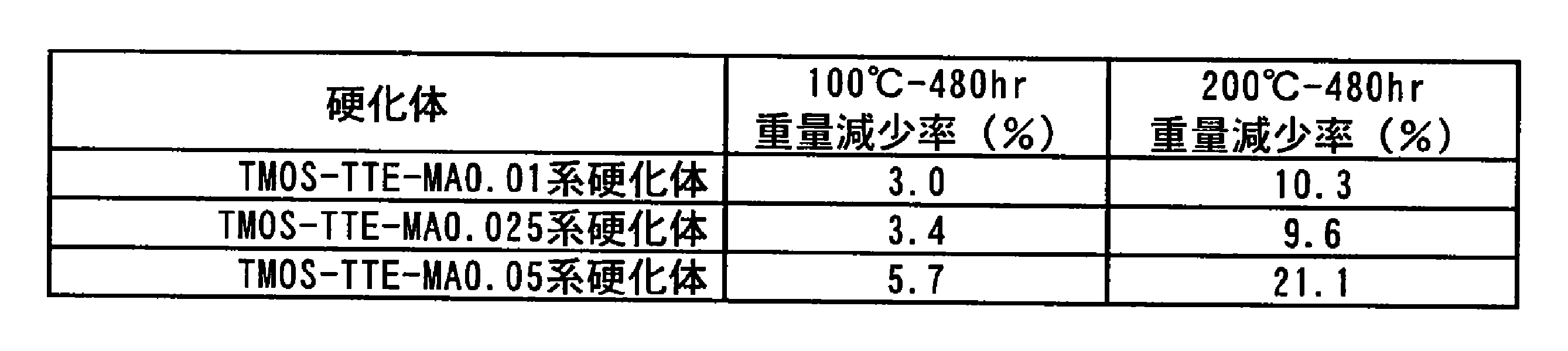
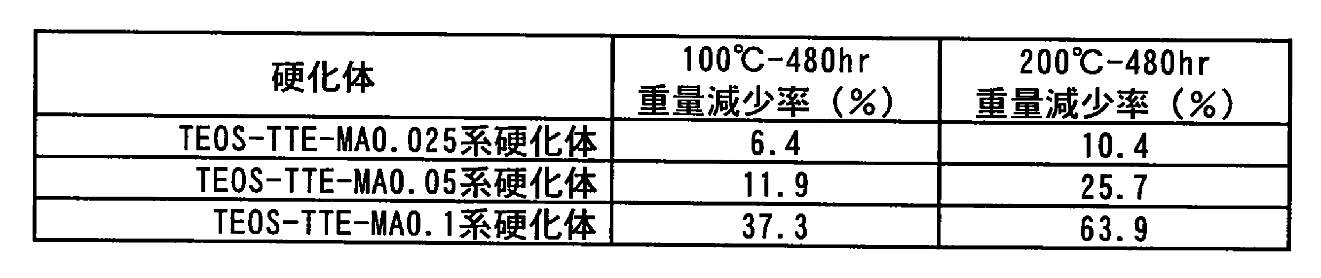
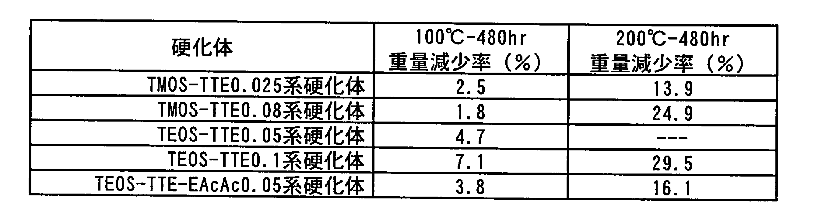
表8および表9に示すように、TMOS-TTE-MA系硬化体およびTEOS-TTE-MA系硬化体は、TTEとMAの添加量が多くなると、耐熱性に劣る。同様に、表10に示すように、TMOS-TTE系硬化体、TEOS-TTE系硬化体およびTEOS-TTE-EAcAc系硬化体においても、TTEの添加量が多くなると耐熱性に劣る。しかし、表4および表6に示すように、TEOS-TTE-MA系硬化体およびTMOS-TTE-MA系硬化体は、TTEとMAの添加量を少なくしても、TMOS-TTE-MA0.01系硬化体を除き、機械的特性に著しい差が見られず、TTE系硬化体やTTE-EAcAc系硬化体より機械的特性に優れている。よって、TTEとMAを適量添加すると、耐熱性を損なうことなく、優れた架橋を得ることができると考えられる。
図6は、TMOS-TTE-MA0.025系硬化体、TMOS-TTE0.025系硬化体およびTMOS-TTE0.08系硬化体の3種試験片を、150℃および200℃に保持された各恒温槽に入れてからの経過時間と残存重量率との関係を示すグラフである(縦軸:残存重量率(%)、横軸:保持時間(時間))。(A)は、150℃保持における残存重量率の変化を、(B)は、200℃保持における残存重量率の変化を、それぞれ示す。図中、実線、点鎖線および破線は、それぞれ、TMOS-TTE-MA0.025系硬化体、TMOS-TTE0.025系硬化体およびTMOS-TTE0.08系硬化体の各残存重量率の変化を示す。
また、表11はTMOS-TTE-MA系硬化体およびMAを含まない硬化体の480時間保持後の重量減少割合を示す表である。

図6および表11に示すように、TTEとMAをTMOS1モルに対して0.025モル添加した硬化体は、150℃および200℃のそれぞれの温度領域でTTEのみの硬化体に対して耐熱性が劣らないことが確認できた。
3.TMOS系の各種硬化体の高温高湿中の劣化評価
TMOS系の3種の硬化体(TMOS-TTE-MA0.025系硬化体、TMOS-TTE0.025系硬化体、TMOS-TTE0.08系硬化体)から、それぞれ、角形(10mm×10mm×1.5mm)に切り出し、角板状の試験片を作製した。また、比較材として、TMOS-Sn0.01系硬化体も同様の条件にて評価した。TMOS系の3種の硬化体は、すべて14日間放置する条件で作製した。また、比較材であるTMOS-Sn0.01系硬化体は、次の条件で作製した。
TMOS系の3種の硬化体(TMOS-TTE-MA0.025系硬化体、TMOS-TTE0.025系硬化体、TMOS-TTE0.08系硬化体)から、それぞれ、角形(10mm×10mm×1.5mm)に切り出し、角板状の試験片を作製した。また、比較材として、TMOS-Sn0.01系硬化体も同様の条件にて評価した。TMOS系の3種の硬化体は、すべて14日間放置する条件で作製した。また、比較材であるTMOS-Sn0.01系硬化体は、次の条件で作製した。
乾燥窒素ガスを流した状態のグローブボックス内にて、蓋付きガラス容器(容量:200ml)中に、PDMS50g、テトラメトキシシラン(Tetramethoxysilane: TMOS、信越化学工業株式会社製、品番:KBM-04)7.612g、ジラウリン酸ジブチル錫(東京化成工業株式会社製、C32H64O4Sn)0.316gを順に入れ、該ガラス容器の蓋を閉めた(モル比にて、PDMS:TMOS:Sn=1:1:0.01)。この内容物を「TMOS-Sn0.01系溶液」とした。次に、グローブボックス外に蓋を閉めた状態の各ガラス容器を取り出した。TMOS-Sn0.01系溶液は、密封雰囲気下において、ガラス容器に乾燥窒素ガスを流しながら、プロペラ付きの攪拌棒を挿入し、40℃に保持されたオイルバスに浸し、撹拌を開始した。40℃にて24時間撹拌後にシャーレに展開し、温度25℃、湿度50%±10%R.H.の雰囲気下に保たれたボックス内で、14日間放置し、硬化体を得た。
高温高湿中の劣化評価は、次の方法で行った。各種試験片を、予め重量測定してから、30gの水と共にPTFE製の容器(内径53mm、外径70mm、高さ90mm、容量100ml、AS ONE株式会社製)中に入れて密閉し、上述と同じ恒温槽内において温度120℃で120時間保持した。120時間経過後に、各試験片を恒温槽から取り出し、予め80℃に保持しておいた別の恒温槽(上記恒温槽と同じ型のもの)に入れて1時間保持した後、各試験片を当該恒温槽および容器から取り出して、1分経過後に重量を測定し、試験前後の重量変化から残存重量率を計算して、劣化の程度を評価した。
図7および表12は、各種TMOS系硬化体の試験片を120℃-120時間保持の条件で評価した残存重量率および重量減少率を示す。
表12中、「TMOS-TTE1-0.025」はTMOS-TTE0.025系硬化体を、「TMOS-TTE1-0.08」はTMOS-TTE0.08系硬化体を、「TMOS-(E-MA)1-0.025」はTMOS-TTE-MA0.025系硬化体を、「TMOS-Sn1-0.01」はTMOS-Sn0.01系硬化体を、それぞれ示す。また(1) (2)はそれぞれの試験片で2個測定したことを表す。

図7および表12に示すように、TMOS-TTE-MA0.025系硬化体はTMOS-TTE0.025及びTMOS-TTE0.08系硬化体と比較して、劣化の程度に大きな差は見られなかった。一方、TMOS-Sn0.01系硬化体は、全硬化体の中で最も大きく劣化していた。この結果より、高湿高温下での耐熱性については、TMOS-TTE-MA系硬化体はTMOS-Sn系硬化体より優れているがわかる。したがって、ポリオルガノシロキサン、シリコンアルコキシド、チタニウムアルコキシド、ヒドロキシカルボン酸エステルを含むポリオルガノシロキサン組成物を硬化させると、ポリオルガノシロキサン、シリコンアルコキシド、Sn系触媒とを含む組成物を硬化させる場合に比べて、高温高湿下における重量減少率の低い硬化体を得ることができる。
<実施例3>
ポリオルガノシロキサン組成物の保存安定性の評価
(1)評価試料
PDMS:TMOS:TTE:MA=1:1:0.025:0.025(モル比)のポリオルガノシロキサン組成物(「TMOS-TTE-MA0.025系溶液」という)、PDMS:TMOS:TTE:EAcAc=1:1:0.025:0.05(モル比)のポリオルガノシロキサン組成物(「TMOS-TTE0.025-EAcAc0.05系溶液」という)およびPDMS:TMOS:Sn=1:1:0.01(モル比)のポリオルガノシロキサン組成物(「TMOS-Sn0.01系溶液」という)の3種の組成物を用いた。
ポリオルガノシロキサン組成物の保存安定性の評価
(1)評価試料
PDMS:TMOS:TTE:MA=1:1:0.025:0.025(モル比)のポリオルガノシロキサン組成物(「TMOS-TTE-MA0.025系溶液」という)、PDMS:TMOS:TTE:EAcAc=1:1:0.025:0.05(モル比)のポリオルガノシロキサン組成物(「TMOS-TTE0.025-EAcAc0.05系溶液」という)およびPDMS:TMOS:Sn=1:1:0.01(モル比)のポリオルガノシロキサン組成物(「TMOS-Sn0.01系溶液」という)の3種の組成物を用いた。
(2)評価方法
上記各試料を40℃の密閉雰囲気下で24時間攪拌した後、上述と同様の形態のスクリュー管瓶に移し、スクリュー管瓶内の溶液に対して6wt%のエタノール(ナカライテスク株式会社)を入れ、混練機(ARE-250T、THINKY CO.製)を用いて、2000rpmにて2分間、続いて1500rpmにて1分間の条件下で撹拌した。その後、40℃の水が入ったビーカに7日、14日、28日間漬けた後にシャーレに展開し、温度25℃、湿度50%±10%R.H.の雰囲気下に保たれたボックス内で7日間放置し、各硬化体を得た。得られた硬化体の引張試験特性を評価した。
上記各試料を40℃の密閉雰囲気下で24時間攪拌した後、上述と同様の形態のスクリュー管瓶に移し、スクリュー管瓶内の溶液に対して6wt%のエタノール(ナカライテスク株式会社)を入れ、混練機(ARE-250T、THINKY CO.製)を用いて、2000rpmにて2分間、続いて1500rpmにて1分間の条件下で撹拌した。その後、40℃の水が入ったビーカに7日、14日、28日間漬けた後にシャーレに展開し、温度25℃、湿度50%±10%R.H.の雰囲気下に保たれたボックス内で7日間放置し、各硬化体を得た。得られた硬化体の引張試験特性を評価した。
表13に、各硬化体を7日間放置する条件にて硬化させたTTE-MA系硬化体、TTE-EAcAc硬化体の各引張特性の評価結果を示す。ただし、TTE-Sn系硬化体は1日でゲル化したので、引張特性評価を行わなかった。
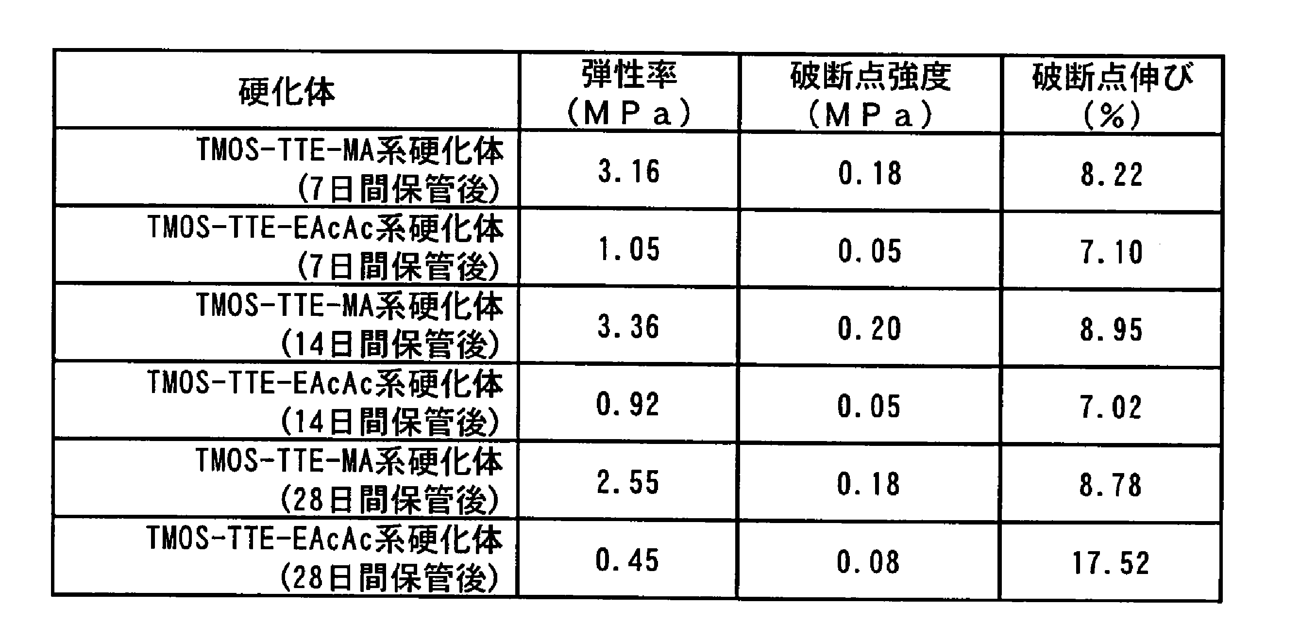
表13より、40℃保管後の引張特性評価においても、MAを添加した硬化体はTTE-EAcAc系硬化体より弾性率、破断点強度ともに優れており、長期保存による機械的特性の劣化は認められなかった。
II.ポリオルガノシロキサン-シリコンアルコキシド-チタニウムアルコキシド-ヒドロキシカルボン酸エステル-フィラー系
<実施例4>
1.PDMS-MTMS/TMOS-TTE-MA-フィラー系の各種硬化体の特性評価
<実施例4>
1.PDMS-MTMS/TMOS-TTE-MA-フィラー系の各種硬化体の特性評価
(1)硬化体の作製方法
乾燥窒素ガスを流した状態のグローブボックス内にて、Mw=30000のPDMS(Gelest製、品番: DMS-S31)50gと、平均粒子径16nmで比表面積130m2/gの疎水性シリカフィラー(日本アエロジル株式会社製、品番: R972)5.721gとを攪拌容器に入れ、混練機(ARE-250T、THINKY CO.製)を用いて混合した後(2000rpmにて5分間)、ミキサー(プロセスホモジナイザーPH91、株式会社エスエムテー製)を用いて高いせん断力を加え混合を行った(5000rpmにて10分間)。次に、乾燥窒素ガスを流した状態のグローブボックス内にて、蓋付きガラス容器中に、上記PDMSとフィラーの混合溶液と、メチルトリメトキシシラン(Methyltrimethoxysilane: MTMS、信越化学工業株式会社製、品番:KBM-13、以後、「MTMS」という。)1.135gとを入れた。次に、グローブボックス内でTTEとMAを同モルでスクリュー管瓶の中に入れ25℃で30分間撹拌したもの0.35gを上記ガラス容器に入れて蓋を閉めた(モル比にて、PDMS:MTMS:TTE:MA=1:5:0.5:0.5、R972はそれ自体も含めたガラス容器内の封入物総重量に対して10wt%)。さらに、MTMSの配合量を、PDMS1モルに対して上記の5モルから、10モルおよび20モルに変化させた2種類の組成物も用意した。この種の内容物を「PDMS-MTMS-TTE-MA-R972系溶液」と称する。
乾燥窒素ガスを流した状態のグローブボックス内にて、Mw=30000のPDMS(Gelest製、品番: DMS-S31)50gと、平均粒子径16nmで比表面積130m2/gの疎水性シリカフィラー(日本アエロジル株式会社製、品番: R972)5.721gとを攪拌容器に入れ、混練機(ARE-250T、THINKY CO.製)を用いて混合した後(2000rpmにて5分間)、ミキサー(プロセスホモジナイザーPH91、株式会社エスエムテー製)を用いて高いせん断力を加え混合を行った(5000rpmにて10分間)。次に、乾燥窒素ガスを流した状態のグローブボックス内にて、蓋付きガラス容器中に、上記PDMSとフィラーの混合溶液と、メチルトリメトキシシラン(Methyltrimethoxysilane: MTMS、信越化学工業株式会社製、品番:KBM-13、以後、「MTMS」という。)1.135gとを入れた。次に、グローブボックス内でTTEとMAを同モルでスクリュー管瓶の中に入れ25℃で30分間撹拌したもの0.35gを上記ガラス容器に入れて蓋を閉めた(モル比にて、PDMS:MTMS:TTE:MA=1:5:0.5:0.5、R972はそれ自体も含めたガラス容器内の封入物総重量に対して10wt%)。さらに、MTMSの配合量を、PDMS1モルに対して上記の5モルから、10モルおよび20モルに変化させた2種類の組成物も用意した。この種の内容物を「PDMS-MTMS-TTE-MA-R972系溶液」と称する。
また、上記のMTMSをTMOSに変え、モル比にて、PDMS:TMOS:TTE:MA=1:5~20:0.5:0.5、R972はガラス容器内の封入物総重量に対して10wt%)とする3種類の組成物を用意した。この種の内容物を「PDMS-TMOS-TTE-MA-R972系溶液」と称する。
次に、グローブボックス外に、蓋を閉めた状態の各ガラス容器を取り出した。上記のPDMS-MTMS-TTE-MA-R972系溶液およびPDMS-TMOS-TTE-MA-R972系溶液は、密封雰囲気下において、ガラス容器に乾燥窒素ガスを流しながら、プロペラ付きの攪拌棒を挿入し、40℃に保持されたオイルバスに浸し、撹拌を開始した。その後、FT-IR測定でSi-O-Ti結合に起因する920cm-1の吸収ピークとGPC測定でMTMSに起因するピークを確認しながら撹拌を行い、Si-O-Ti結合とMTMSに起因するピークが消滅したことを確認した。その後シャーレに展開し、温度25℃、湿度50%±10%R.H.の雰囲気下に保たれたボックス内で168時間(7日間)放置し、各硬化体を得た(PDMS-MTMS-TTE-MA-R972系硬化体(7))。同様の手法により、PDMS-TMOS-TTE-MA-R972系溶液を7日間放置して、各硬化体を得た(PDMS-TMOS-TTE-MA-R972系硬化体(7))。比較のため、MAを加えない系の溶液(PDMS-MTMS-TTE-R972系溶液)も用意し、上記と同様の方法にて7日間放置して、各硬化体を得た(PDMS-MTMS-TTE-R972系硬化体(7))。
また、上記のPDMS-MTMS-TTE-MA-R972系溶液およびPDMS-TMOS-TTE-MA-R972系溶液をそれぞれ上記と同様に攪拌した後、シャーレに展開し、温度25℃、湿度50%±10%R.H.の雰囲気下に保たれたボックス内で168時間(7日間)放置し、各硬化体を得た。得られた各硬化体からダンベル試料を打ち抜き、温度100℃の乾燥機内で20日放置した(PDMS-MTMS-TTE-MA-R972系硬化体100℃(20)、PDMS-TMOS-TTE-MA-R972系硬化体100℃(20)。また、乾燥機内の温度を200℃にする以外は同じ条件で放置した(PDMS-MTMS-TTE-MA-R972系硬化体200℃(20)、PDMS-TMOS-TTE-MA-R972系硬化体200℃(20))。
(2)引張特性評価
前述と同様の方法にて、上記各種硬化体の引張特性を評価した。
前述と同様の方法にて、上記各種硬化体の引張特性を評価した。
図8は、シリコンアルコキシドのモル比を変化させたときのPDMS-MTMS-TTE-MA-R972系硬化体(7)およびPDMS-TMOS-TTE-MA-R972系硬化体(7)の各引張特性を示すグラフである。図8中の黒三角のプロットはシリコンアルコキシドにMTMSを用いた系を、白四角のプロットはシリコンアルコキシドにTMOSを用いた系を、それぞれ示す。
図8に示す結果から、シリコンアルコキシドとしてMTMSを用いるとその含有率が高くなる程、破断点強度が大きくなる傾向がある一方、シリコンアルコキシドとしてTMOSを用いるとその含有率が高くなる程、破断点強度が小さくなる傾向があることがわかった。破断点強度の目標値を2MPaとした場合、シリコンアルコキシドとして10モル比以上のMTMSを用いた硬化体がその目標値に到達した。
図9は、MTMSのモル比を変化させたときのPDMS-MTMS-TTE-MA-R972系硬化体(7)、PDMS-MTMS-TTE-MA-R972系硬化体100℃(20)およびPDMS-MTMS-TTE-MA-R972系硬化体200℃(20)の各引張特性を示すグラフである。図9中の白三角のプロットは室温で7日放置の条件、黒三角のプロットは100℃で20日放置の条件、黒丸のプロットは200℃で20日放置の条件で作製した各硬化体を示す。
図10は、TMOSのモル比を変化させたときのPDMS-TMOS-TTE-MA-R972系硬化体(7)、PDMS-TMOS-TTE-MA-R972系硬化体100℃(20)およびPDMS-TMOS-TTE-MA-R972系硬化体200℃(20)の各引張特性を示すグラフである。図10中の白四角のプロットは室温で7日放置の条件、黒四角のプロットは100℃で20日放置の条件、黒丸のプロットは200℃で20日放置の条件で作製した各硬化体を示す。
図9および図10に示す結果から、100℃以上の温度下で硬化させた方が破断点強度および破断点伸びの向上が認められるものの、硬化条件の違いによる大きな特性の向上は認められなかった。
図11は、MTMSのモル比を変化させたときのPDMS-MTMS-TTE-MA-R972系硬化体(7)およびPDMS-MTMS-TTE-R972系硬化体(7)の各引張特性を示すグラフである。図11中の白菱形のプロットはMAを用いない系で、黒菱形のプロットはMAを用いた系で作製した各硬化体を示す。
図11に示す結果から、TTEにさらにMAを加えることにより、弾性率および破断点強度の向上が認められた。
(3)長期等温劣化特性評価
実施例2の「2.TEOS系とTMOS系の各種硬化体の耐熱性評価(一定温度保持による熱重量減少の評価)」と同様の方法にて、上記各種硬化体の長期等温劣化特性を評価した。
実施例2の「2.TEOS系とTMOS系の各種硬化体の耐熱性評価(一定温度保持による熱重量減少の評価)」と同様の方法にて、上記各種硬化体の長期等温劣化特性を評価した。
図12は、MTMSまたはTMOSを5~20モル比の範囲で変化させて作製したPDMS-MTMS-TTE-MA-R972系硬化体(7)およびPDMS-TMOS-TTE-MA-R972系硬化体(7)を、100℃に保持された恒温槽に入れてからの経過時間と残存重量率との関係を示すグラフである(縦軸:残存重量率(%)、横軸:保持時間(時間))。また、図13は、これら両硬化体に対して、200℃に保持された恒温槽を用いて同様の評価を行ったときの経過時間と残存重量率との関係を示すグラフである(縦軸:残存重量率(%)、横軸:保持時間(時間))。表14は、図12および図13における各硬化体の480時間後の重量減少率を比較して示す表である。

図12、図13および表14に示す結果から、シリコンアルコキシドにMTMSおよびTMOSをそれぞれ用いて作製した両種硬化体を比較すると、TMOSを用いたほうが、定温で長時間保持したときの重量減少が低く、優れていることがわかった。また、MTMSを用いた場合には、その含有量が多い程、重量減少が小さく、定温での耐熱性が高い傾向があることがわかった。
(4)密封高温多湿劣化特性評価
実施例2の「3.TMOS系の各種硬化体の高温高湿中の劣化評価」と同様の方法にて、上記各種硬化体の密封高温多湿劣化特性を評価した。
実施例2の「3.TMOS系の各種硬化体の高温高湿中の劣化評価」と同様の方法にて、上記各種硬化体の密封高温多湿劣化特性を評価した。
図14および表15は、それぞれ、MTMSまたはTMOSを5~20モル比の範囲で変化させて作製したPDMS-MTMS-TTE-MA-R972系硬化体(7)およびPDMS-TMOS-TTE-MA-R972系硬化体(7)を120℃にて120時間保持したときの各重量減少率を比較して示す図および表である。
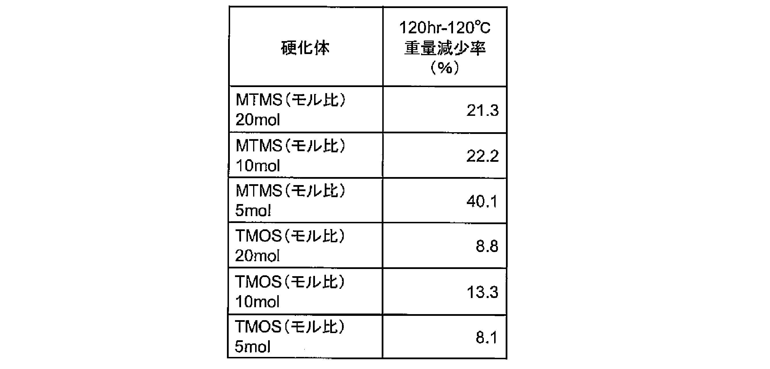
図14および表15に示す結果から、シリコンアルコキシドにMTMSおよびTMOSをそれぞれ用いて作製した両種硬化体を比較すると、TMOSを用いたほうが、密閉雰囲気下における高温多湿条件で劣化しにくいことがわかった。
2.チタニウムアルコキシドおよびヒドロキシカルボン酸エステルの各量を変化させたPDMS-MTMS/TMOS-TTE-MA-フィラー系の各種硬化体の特性評価
(1)硬化体の作製方法
TTEとMAを等モルとしつつ、TTEおよびMAを総量で0.14~0.70g(PDMS1モルに対してTTEおよびMAを、それぞれ0.2~1.0モル)に変えて、MTMS若しくはTMOSのPDMSに対するモル比を5とし、その他は実施例4の(1)と同じ条件にて各硬化体を作製した。
(1)硬化体の作製方法
TTEとMAを等モルとしつつ、TTEおよびMAを総量で0.14~0.70g(PDMS1モルに対してTTEおよびMAを、それぞれ0.2~1.0モル)に変えて、MTMS若しくはTMOSのPDMSに対するモル比を5とし、その他は実施例4の(1)と同じ条件にて各硬化体を作製した。
(2)引張特性評価
前述と同様の方法にて、上記各種硬化体の引張特性を評価した。
前述と同様の方法にて、上記各種硬化体の引張特性を評価した。
図15は、TTE、MAのモル比を変化させて作製したPDMS-MTMS-TTE-MA-R972系硬化体(7)およびPDMS-MTMS-TTE-R972系硬化体(7)の各引張特性を示すグラフである。図15中の白菱形のプロットはMAを用いない系で、黒菱形のプロットはMAを用いた系で作製した各硬化体を示す。
図15に示す結果から、TTEのみならず、MAを加えることにより、弾性率および破断点強度の向上、破断時の伸びが大きくなる傾向があることがわかった。また、TTEおよびMAのPDMSに対するモル比が0.3の条件で作製した硬化体が最も高い破断点強度を有していることがわかった。TTEおよびMAのPDMSに対するモル比が0.3~0.5の範囲のときに、破断点強度が1.8MPa以上の高強度が得られた。
(3)長期等温劣化特性評価
実施例2の「2.TEOS系とTMOS系の各種硬化体の耐熱性評価(一定温度保持による熱重量減少の評価)」と同様の方法にて、上記各種硬化体の長期等温劣化特性を評価した。
実施例2の「2.TEOS系とTMOS系の各種硬化体の耐熱性評価(一定温度保持による熱重量減少の評価)」と同様の方法にて、上記各種硬化体の長期等温劣化特性を評価した。
図16は、TTEおよびMAをともに0.3モル比としたときのPDMS-MTMS-TTE-MA-R972系硬化体(7)およびPDMS-TMOS-TTE-MA-R972系硬化体(7)を、100℃に保持された恒温槽に入れてからの経過時間と残存重量率との関係を示すグラフである(縦軸:残存重量率(%)、横軸:保持時間(時間))。また、図17は、200℃に保持された恒温槽を用いて同様の評価を行ったときの経過時間と残存重量率との関係を示すグラフである(縦軸:残存重量率(%)、横軸:保持時間(時間))。
図16および図17に示す結果から、シリコンアルコキシドにMTMSおよびTMOSをそれぞれ用いて作製した両種硬化体を比較すると、TMOSを用いたほうが、定温で長時間保持したときの重量減少が低く、優れていることがわかった。また、図12および図13に示す結果と比較すると明らかなように、TTEおよびMAの含有量を、0.5モル比から0.3モル比に減らすことにより、重量減少をより低くすることができることがわかった。
図18および図19は、それぞれ、TTEおよびMAをともに0.2~0.5モル比の範囲で変化させて作製したPDMS-MTMS-TTE-MA-R972系硬化体(7)を100℃および200℃にそれぞれ保持された恒温槽に入れてからの経過時間と残存重量率との関係を示す図である。表16は、図18および図19における各硬化体の480時間後の重量減少率を示す表である。また、図20および図21は、それぞれ、TTEを0.3~1.0モル比の範囲で変化させて作製したPDMS-MTMS-TTE-R972系硬化体(7)を100℃および200℃にそれぞれ保持された恒温槽に入れてからの経過時間と残存重量率との関係を示す図である。表17は、図20および図21における各硬化体の480時間後の重量減少率を示す表である。
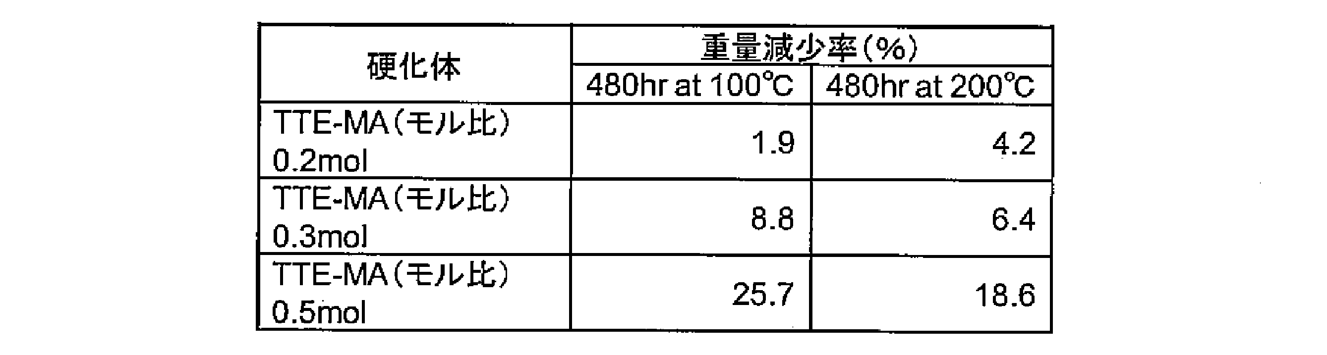

上記の結果から、TTEの含有量、あるいはTTEとMAの含有量が低い程、定温で長時間保持したときの重量減少が低く、優れていることがわかった。
(4)密封高温多湿劣化特性評価
実施例2の「3.TMOS系の各種硬化体の高温高湿中の劣化評価」と同様の方法にて、上記各種硬化体の密封高温多湿劣化特性を評価した。
実施例2の「3.TMOS系の各種硬化体の高温高湿中の劣化評価」と同様の方法にて、上記各種硬化体の密封高温多湿劣化特性を評価した。
図22は、TTEおよびMAをともに0.3モル比としたときのPDMS-MTMS-TTE-MA-R972系硬化体(7)およびPDMS-TMOS-TTE-MA-R972系硬化体(7)を、120℃にて120時間保持したときの各重量減少率を比較して示す図である。
図22に示す結果から、図14に示す結果と同様、シリコンアルコキシドにTMOSを用いたほうが、密閉雰囲気下における高温多湿条件で劣化しにくいことがわかった。
図23は、TTEおよびMAをともに0.2~0.5モル比の範囲で変化させて作製したPDMS-MTMS-TTE-MA-R972系硬化体(7)を、120℃にて120時間保持したときの各重量減少率を比較して示す図である。また、図24は、TTEを0.3~1.0モル比の範囲で変化させて作製したPDMS-MTMS-TTE-R972系硬化体(7)を、120℃にて120時間保持したときの各重量減少率を比較して示す図である。
図23および図24に示す結果から、TTEにMAを加えると、重量減少が大きくなる傾向にあるものの、TTEとMAとをそれぞれ0.2モル比とすることで、重量減少を大きく抑制できることがわかった。
本発明は、例えば、接着剤、シール材等に利用可能である。
Claims (10)
- (A)1分子中の少なくとも一方の末端がシラノール変性したポリオルガノシロキサンと、
(B)上記ポリオルガノシロキサン1モルに対して0.5~30モルのシリコンアルコキシドと、
(C)上記ポリオルガノシロキサン1モルに対して0.01~2モルのチタニウムアルコキシドと、
(D)上記ポリオルガノシロキサン1モルに対して0.01~2モルのヒドロキシカルボン酸エステルと、
を含むことを特徴とするポリオルガノシロキサン組成物。 - 前記ポリオルガノシロキサン組成物の全重量に対して2~30重量%を占める無機フィラーを、さらに含むことを特徴とする請求項1に記載のポリオルガノシロキサン組成物。
- 前記シリコンアルコキシド(B)を、前記ポリオルガノシロキサン(A)1モルに対して5~20モル含むことを特徴とする請求項1または請求項2に記載のポリオルガノシロキサン組成物。
- 前記ヒドロキシカルボン酸エステル(D)は、リンゴ酸ジアルキルエステルであることを特徴とする請求項1から請求項3のいずれか1項に記載のポリオルガノシロキサン組成物。
- 前記チタニウムアルコキシド(C)および前記ヒドロキシカルボン酸エステル(D)を、それぞれ、前記ポリオルガノシロキサン(A)1モルに対して0.3~0.5モル含むことを特徴とする請求項1から請求項4のいずれか1項に記載のポリオルガノシロキサン組成物。
- 請求項1から請求項5のいずれか1項に記載のポリオルガノシロキサン組成物を硬化したポリオルガノシロキサン組成物硬化体。
- (A)1分子中の少なくとも一方の末端がシラノール変性したポリオルガノシロキサンと、
(B)上記ポリオルガノシロキサン1モルに対して0.5~4モルのシリコンアルコキシドと、
(C)上記ポリオルガノシロキサン1モルに対して0.01~0.5モルのチタニウムアルコキシドと、
(D)上記ポリオルガノシロキサン1モルに対して0.01~0.5モルのヒドロキシカルボン酸エステルと、
を含むことを特徴とするポリオルガノシロキサン組成物。 - 前記ヒドロキシカルボン酸エステルは、リンゴ酸ジアルキルエステルであることを特徴とする請求項7に記載のポリオルガノシロキサン組成物。
- 前記チタニウムアルコキシド(C)および前記ヒドロキシカルボン酸エステル(D)を、それぞれ、前記ポリオルガノシロキサン(A)1モルに対して0.02~0.1モル含むことを特徴とする請求項7または請求項8に記載のポリオルガノシロキサン組成物。
- 請求項7から請求項9のいずれか1項に記載のポリオルガノシロキサン組成物を硬化したポリオルガノシロキサン組成物硬化体。
Priority Applications (1)
| Application Number | Priority Date | Filing Date | Title |
|---|---|---|---|
| JP2011518228A JP5597859B2 (ja) | 2009-06-10 | 2010-05-13 | ポリオルガノシロキサン組成物およびその硬化体 |
Applications Claiming Priority (2)
| Application Number | Priority Date | Filing Date | Title |
|---|---|---|---|
| JP2009-139256 | 2009-06-10 | ||
| JP2009139256 | 2009-06-10 |
Publications (1)
| Publication Number | Publication Date |
|---|---|
| WO2010143357A1 true WO2010143357A1 (ja) | 2010-12-16 |
Family
ID=43308620
Family Applications (1)
| Application Number | Title | Priority Date | Filing Date |
|---|---|---|---|
| PCT/JP2010/003242 Ceased WO2010143357A1 (ja) | 2009-06-10 | 2010-05-13 | ポリオルガノシロキサン組成物およびその硬化体 |
Country Status (2)
| Country | Link |
|---|---|
| JP (1) | JP5597859B2 (ja) |
| WO (1) | WO2010143357A1 (ja) |
Cited By (13)
| Publication number | Priority date | Publication date | Assignee | Title |
|---|---|---|---|---|
| JP2013173879A (ja) * | 2012-02-27 | 2013-09-05 | Shinshu Univ | シリコーンゴム組成物およびその製造方法ならびにシリコーンゴム |
| EP2343341A4 (en) * | 2008-10-23 | 2013-10-02 | Univ Mie | POLYORGANOSILOXANE COMPOSITION AND HARDENING PRODUCT THEREOF |
| JP2014058609A (ja) * | 2012-09-14 | 2014-04-03 | Mie Univ | シリコーン組成物 |
| CN107207860A (zh) * | 2015-01-28 | 2017-09-26 | 美国道康宁公司 | 弹性体组合物及其应用 |
| US20170292029A1 (en) * | 2014-09-19 | 2017-10-12 | Mie University | Electrophoretic deposition fluid, metal core substrate, and method for fabricating the metal core substrate |
| KR20190025723A (ko) * | 2016-08-03 | 2019-03-11 | 다우 실리콘즈 코포레이션 | 탄성중합체 조성물 및 그의 응용 |
| JP2019515100A (ja) * | 2016-05-06 | 2019-06-06 | ダウ シリコーンズ コーポレーション | シリコーン系材料を基材に接着させる方法 |
| JP2019526001A (ja) * | 2016-08-03 | 2019-09-12 | ダウ シリコーンズ コーポレーション | シリコーン材料を含む布地ケア組成物 |
| JP2020520394A (ja) * | 2017-05-09 | 2020-07-09 | ダウ シリコーンズ コーポレーション | 積層接着剤組成物及びその使用 |
| US10844177B2 (en) | 2016-08-03 | 2020-11-24 | Dow Silicones Corporation | Elastomeric compositions and their applications |
| US11090253B2 (en) | 2016-08-03 | 2021-08-17 | Dow Silicones Corporation | Cosmetic composition comprising silicone materials |
| US11479022B2 (en) | 2017-05-09 | 2022-10-25 | Dow Silicones Corporation | Lamination process |
| US12534576B2 (en) | 2015-01-28 | 2026-01-27 | Dow Silicones Corporation | Elastomeric compositions and their applications |
Citations (5)
| Publication number | Priority date | Publication date | Assignee | Title |
|---|---|---|---|---|
| DE4213875A1 (de) * | 1992-04-28 | 1993-11-04 | Bayer Ag | Polysiloxanmasse |
| DE4213873A1 (de) * | 1992-04-28 | 1993-11-04 | Bayer Ag | Polysiloxanmassen |
| JPH07304953A (ja) * | 1992-12-17 | 1995-11-21 | Bayer Ag | 新規なチタン(iv)キレート類及びそのポリシロキサン材料における使用法 |
| WO2010047109A1 (ja) * | 2008-10-23 | 2010-04-29 | 国立大学法人三重大学 | ポリオルガノシロキサン組成物およびその硬化体 |
| JP2010121111A (ja) * | 2008-10-23 | 2010-06-03 | Mie Univ | ポリオルガノシロキサン組成物およびその硬化体 |
-
2010
- 2010-05-13 JP JP2011518228A patent/JP5597859B2/ja not_active Expired - Fee Related
- 2010-05-13 WO PCT/JP2010/003242 patent/WO2010143357A1/ja not_active Ceased
Patent Citations (5)
| Publication number | Priority date | Publication date | Assignee | Title |
|---|---|---|---|---|
| DE4213875A1 (de) * | 1992-04-28 | 1993-11-04 | Bayer Ag | Polysiloxanmasse |
| DE4213873A1 (de) * | 1992-04-28 | 1993-11-04 | Bayer Ag | Polysiloxanmassen |
| JPH07304953A (ja) * | 1992-12-17 | 1995-11-21 | Bayer Ag | 新規なチタン(iv)キレート類及びそのポリシロキサン材料における使用法 |
| WO2010047109A1 (ja) * | 2008-10-23 | 2010-04-29 | 国立大学法人三重大学 | ポリオルガノシロキサン組成物およびその硬化体 |
| JP2010121111A (ja) * | 2008-10-23 | 2010-06-03 | Mie Univ | ポリオルガノシロキサン組成物およびその硬化体 |
Non-Patent Citations (2)
| Title |
|---|
| HIROAKI CHO ET AL.: "Development of a novel silicone compound with high thermal endurance", IEICE TECHNICAL REPORT, vol. 108, no. 387, 14 January 2009 (2009-01-14), pages 43 - 48 * |
| YASUNORI ASHIDA ET AL.: "A new low temperature vulcanized silicone compound", IEICE TECHNICAL REPORT, vol. 108, no. 387, 14 January 2009 (2009-01-14), pages 49 - 54 * |
Cited By (27)
| Publication number | Priority date | Publication date | Assignee | Title |
|---|---|---|---|---|
| EP2343341A4 (en) * | 2008-10-23 | 2013-10-02 | Univ Mie | POLYORGANOSILOXANE COMPOSITION AND HARDENING PRODUCT THEREOF |
| WO2013128497A1 (ja) * | 2012-02-27 | 2013-09-06 | 国立大学法人信州大学 | シリコーンゴム組成物およびその製造方法ならびにシリコーンゴム |
| JP2013173879A (ja) * | 2012-02-27 | 2013-09-05 | Shinshu Univ | シリコーンゴム組成物およびその製造方法ならびにシリコーンゴム |
| JP2014058609A (ja) * | 2012-09-14 | 2014-04-03 | Mie Univ | シリコーン組成物 |
| US20170292029A1 (en) * | 2014-09-19 | 2017-10-12 | Mie University | Electrophoretic deposition fluid, metal core substrate, and method for fabricating the metal core substrate |
| US10563015B2 (en) | 2015-01-28 | 2020-02-18 | Dow Silicones Corporation | Elastomeric compositions and their applications |
| US11332581B2 (en) | 2015-01-28 | 2022-05-17 | Dow Silicones Corporation | Elastomeric compositions and their applications |
| US12534576B2 (en) | 2015-01-28 | 2026-01-27 | Dow Silicones Corporation | Elastomeric compositions and their applications |
| JP7116034B2 (ja) | 2015-01-28 | 2022-08-09 | ダウ シリコーンズ コーポレーション | エラストマー組成物及びその使用 |
| JP2018503725A (ja) * | 2015-01-28 | 2018-02-08 | ダウ コーニング コーポレーションDow Corning Corporation | エラストマー組成物及びその使用 |
| CN107207860B (zh) * | 2015-01-28 | 2021-03-30 | 美国陶氏有机硅公司 | 弹性体组合物及其应用 |
| JP2020019965A (ja) * | 2015-01-28 | 2020-02-06 | ダウ シリコーンズ コーポレーション | エラストマー組成物及びその使用 |
| CN107207860A (zh) * | 2015-01-28 | 2017-09-26 | 美国道康宁公司 | 弹性体组合物及其应用 |
| US10774250B2 (en) | 2016-05-06 | 2020-09-15 | Dow Silicones Corporation | Adhesive compositions and their applications |
| JP2019515100A (ja) * | 2016-05-06 | 2019-06-06 | ダウ シリコーンズ コーポレーション | シリコーン系材料を基材に接着させる方法 |
| US10808154B2 (en) | 2016-08-03 | 2020-10-20 | Dow Silicones Corporation | Elastomeric compositions and their applications |
| KR102124300B1 (ko) * | 2016-08-03 | 2020-06-22 | 다우 실리콘즈 코포레이션 | 탄성중합체 조성물 및 그의 응용 |
| US10844177B2 (en) | 2016-08-03 | 2020-11-24 | Dow Silicones Corporation | Elastomeric compositions and their applications |
| JP2019527276A (ja) * | 2016-08-03 | 2019-09-26 | ダウ シリコーンズ コーポレーション | エラストマー組成物及びその用途 |
| US11090253B2 (en) | 2016-08-03 | 2021-08-17 | Dow Silicones Corporation | Cosmetic composition comprising silicone materials |
| JP2019526001A (ja) * | 2016-08-03 | 2019-09-12 | ダウ シリコーンズ コーポレーション | シリコーン材料を含む布地ケア組成物 |
| US11485936B2 (en) | 2016-08-03 | 2022-11-01 | Dow Silicones Corporation | Fabric care composition comprising silicone materials |
| KR20190025723A (ko) * | 2016-08-03 | 2019-03-11 | 다우 실리콘즈 코포레이션 | 탄성중합체 조성물 및 그의 응용 |
| US11254847B2 (en) | 2017-05-09 | 2022-02-22 | Dow Silicones Corporation | Lamination adhesive compositions and their applications |
| JP2020520394A (ja) * | 2017-05-09 | 2020-07-09 | ダウ シリコーンズ コーポレーション | 積層接着剤組成物及びその使用 |
| US11479022B2 (en) | 2017-05-09 | 2022-10-25 | Dow Silicones Corporation | Lamination process |
| JP7254030B2 (ja) | 2017-05-09 | 2023-04-07 | ダウ シリコーンズ コーポレーション | 積層接着剤組成物及びその使用 |
Also Published As
| Publication number | Publication date |
|---|---|
| JP5597859B2 (ja) | 2014-10-01 |
| JPWO2010143357A1 (ja) | 2012-11-22 |
Similar Documents
| Publication | Publication Date | Title |
|---|---|---|
| JP5597859B2 (ja) | ポリオルガノシロキサン組成物およびその硬化体 | |
| EP1167455B1 (en) | Room temperature rapid-curable silicone composition | |
| KR101527231B1 (ko) | 실온 경화성 오르가노폴리실록산 조성물 | |
| JP6092491B1 (ja) | 室温硬化性ポリオルガノシロキサン組成物およびその調製方法 | |
| CN105829449B (zh) | 多成分系室温固化性有机聚硅氧烷组合物和该组合物的固化物以及包括该固化物的成型物 | |
| JP5555956B2 (ja) | ポリオルガノシロキサン組成物およびその硬化体 | |
| JP2011506744A (ja) | エラストマーに室温加硫可能なオルガノポリシロキサン組成物及び新規なオルガノポリシロキサン重縮合触媒 | |
| JP7444857B2 (ja) | 室温硬化性オルガノポリシロキサン組成物および電気・電子部品の保護剤または接着剤組成物 | |
| WO2019116892A1 (ja) | 室温湿気硬化型シリコーンゲル組成物及びその硬化物並びに物品 | |
| TWI894137B (zh) | 二元型室溫縮合固化性有機聚矽氧烷組合物 | |
| JP5429968B2 (ja) | ポリオルガノシロキサン組成物およびその硬化体 | |
| JP5608909B2 (ja) | 室温硬化性ポリオルガノシロキサン組成物 | |
| CN101027342A (zh) | 含氮的有机聚硅氧烷及其在可交联组合物中的用途 | |
| JP6490367B2 (ja) | 室温硬化性ポリオルガノシロキサン組成物 | |
| JP3970484B2 (ja) | 自動車用室温硬化性シール材組成物 | |
| KR20220118392A (ko) | 수분 경화성 네트워크 실리콘 중합체 및 그의 용도 | |
| JP7140009B2 (ja) | 自動車オイルシール用室温硬化性オルガノポリシロキサン組成物及びその製造方法 | |
| JP2010100764A (ja) | 素焼き素材塗工液 | |
| JP7604931B2 (ja) | 室温硬化性オルガノポリシロキサン組成物の製造方法及び室温硬化性オルガノポリシロキサン組成物、接着剤、シーリング材並びに物品 | |
| JP2024102808A (ja) | 室温硬化性オルガノポリシロキサン組成物の製造方法及び室温硬化性オルガノポリシロキサン組成物 | |
| KR20260010345A (ko) | 실온 경화성 오르가노폴리실록산 조성물 및 그 제조 방법 | |
| JP2011140582A (ja) | 室温硬化性ポリオルガノシロキサン組成物 | |
| JP2012126808A (ja) | 室温硬化性オルガノポリシロキサン組成物 | |
| WO2025033098A1 (ja) | 液状シリコーンゴム組成物 | |
| JP2017095603A (ja) | 室温硬化性ポリオルガノシロキサン組成物 |
Legal Events
| Date | Code | Title | Description |
|---|---|---|---|
| 121 | Ep: the epo has been informed by wipo that ep was designated in this application |
Ref document number: 10785889 Country of ref document: EP Kind code of ref document: A1 |
|
| WWE | Wipo information: entry into national phase |
Ref document number: 2011518228 Country of ref document: JP |
|
| NENP | Non-entry into the national phase |
Ref country code: DE |
|
| 122 | Ep: pct application non-entry in european phase |
Ref document number: 10785889 Country of ref document: EP Kind code of ref document: A1 |