WO2010125914A1 - スロットルボディ半製品の成形用金型装置 - Google Patents
スロットルボディ半製品の成形用金型装置 Download PDFInfo
- Publication number
- WO2010125914A1 WO2010125914A1 PCT/JP2010/056659 JP2010056659W WO2010125914A1 WO 2010125914 A1 WO2010125914 A1 WO 2010125914A1 JP 2010056659 W JP2010056659 W JP 2010056659W WO 2010125914 A1 WO2010125914 A1 WO 2010125914A1
- Authority
- WO
- WIPO (PCT)
- Prior art keywords
- mold
- throttle body
- main
- boss
- hole
- Prior art date
- Legal status (The legal status is an assumption and is not a legal conclusion. Google has not performed a legal analysis and makes no representation as to the accuracy of the status listed.)
- Ceased
Links
Images






Classifications
-
- F—MECHANICAL ENGINEERING; LIGHTING; HEATING; WEAPONS; BLASTING
- F02—COMBUSTION ENGINES; HOT-GAS OR COMBUSTION-PRODUCT ENGINE PLANTS
- F02D—CONTROLLING COMBUSTION ENGINES
- F02D9/00—Controlling engines by throttling air or fuel-and-air induction conduits or exhaust conduits
- F02D9/08—Throttle valves specially adapted therefor; Arrangements of such valves in conduits
- F02D9/10—Throttle valves specially adapted therefor; Arrangements of such valves in conduits having pivotally-mounted flaps
- F02D9/107—Manufacturing or mounting details
-
- B—PERFORMING OPERATIONS; TRANSPORTING
- B22—CASTING; POWDER METALLURGY
- B22D—CASTING OF METALS; CASTING OF OTHER SUBSTANCES BY THE SAME PROCESSES OR DEVICES
- B22D17/00—Pressure die casting or injection die casting, i.e. casting in which the metal is forced into a mould under high pressure
-
- B—PERFORMING OPERATIONS; TRANSPORTING
- B22—CASTING; POWDER METALLURGY
- B22D—CASTING OF METALS; CASTING OF OTHER SUBSTANCES BY THE SAME PROCESSES OR DEVICES
- B22D17/00—Pressure die casting or injection die casting, i.e. casting in which the metal is forced into a mould under high pressure
- B22D17/20—Accessories: Details
- B22D17/22—Dies; Die plates; Die supports; Cooling equipment for dies; Accessories for loosening and ejecting castings from dies
-
- F—MECHANICAL ENGINEERING; LIGHTING; HEATING; WEAPONS; BLASTING
- F02—COMBUSTION ENGINES; HOT-GAS OR COMBUSTION-PRODUCT ENGINE PLANTS
- F02D—CONTROLLING COMBUSTION ENGINES
- F02D9/00—Controlling engines by throttling air or fuel-and-air induction conduits or exhaust conduits
- F02D9/08—Throttle valves specially adapted therefor; Arrangements of such valves in conduits
- F02D9/10—Throttle valves specially adapted therefor; Arrangements of such valves in conduits having pivotally-mounted flaps
- F02D9/1035—Details of the valve housing
- F02D9/1055—Details of the valve housing having a fluid by-pass
Definitions
- the present invention provides a first and second cylindrical body portions having an intake passage inside, and both end portions of a valve shaft of a throttle valve which is integrally formed on both side walls of the cylindrical portion and opens and closes the intake passage.
- the present invention relates to an improvement of a mold apparatus for molding a throttle body semi-finished product having a bearing boss.
- Patent Document 1 A mold device for molding a semifinished throttle body is already known as disclosed in Patent Document 1.
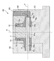
- a conventional mold device for molding a half-finished throttle body includes the first and second main molds that open and close each other along the axis of the intake passage, and the left and right side surfaces of the first and second main molds. It comprises a pair of left and right slide molds that are slidably supported by one of the first and second main molds so as to open and close in the direction along the axis of the valve shaft. A first core pin corresponding to one half and a second core pin corresponding to the other half of the valve shaft are connected to the other slide type, respectively. A cavity for forming the throttle body semi-finished product is formed between the first slide mold and the second slide mold so as to surround the first core pin and the second core pin.
- an expensive mold requires at least four of the first and second main molds and the first and second slide molds, which increases the cost of manufacturing the molds, which reduces the product cost. Will interfere.
- the present invention has been made in view of such circumstances, and includes a first and second main mold, a single slide mold, a fully closed stopper boss disposed on one side of the first bearing boss, It is an object of the present invention to provide a mold device for molding a throttle body semi-finished product that enables molding of a throttle body semi-finished product including a sensor support boss disposed on one side of a second bearing boss.
- the present invention provides a cylindrical body having an intake passage inside, and both end portions of a valve shaft of a throttle valve which is integrally formed on both side walls of the cylindrical portion and opens and closes the intake passage.
- the first and second bearing bosses for supporting the first and second bearing bosses are connected to the outer side of the cylindrical body, and the fully-closed stopper bosses arranged on one side of the first bearing boss are connected to the outer side of the cylindrical part,
- a sensor support boss disposed on one side of the two bearing bosses, and the first and second bearing bosses are provided with a first pilot hole for processing a shaft hole into which the valve shaft is rotatably fitted.
- the sensor support boss is provided with a second lower hole for screw hole processing for screwing the casing of the throttle opening sensor fitted to the second bearing boss in parallel with the axis of the valve shaft,
- the fully closed stopper boss is screwed with a fully closed stopper bolt that regulates the fully closed position of the throttle valve.
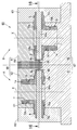
- One of the main molds is provided with a third core pin arranged corresponding to the third lower hole, and the first main mold, the second main mold, and the single slide mold are connected to each other.
- a first feature is that a cavity for molding the throttle body semi-finished product is formed so as to surround the third core pin.
- the throttle body semi-finished product includes an idle adjustment boss disposed on one side of the second bearing boss and connected to the cylinder portion.
- the fifth lower hole for screw hole machining for screwing the idle adjustment valve is provided in parallel with the axis of the valve shaft, and the fifth core pin corresponding to the fifth lower hole is connected to the slide type.
- a third feature is that a cavity for forming the throttle body semi-finished product is formed between the first main mold, the second main mold and the single slide mold so as to surround the fifth core pin. .
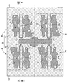
- the present invention provides a common runner between at least two sets of the first and second main molds and the slide mold, and sandwiches the runner.
- One set of the first and second main molds and the slide mold and the other set of the first and second main molds and the slide mold are arranged point-symmetrically, and one set of the first main mold and the other set
- the second main mold is integrally formed to form a first composite mold, and one set of the second main mold and the other set of the first main mold are formed integrally to form the second composite mold.
- the configuration is the fourth feature.
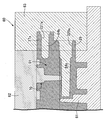
- the present invention is characterized in that the cavity is formed so as to cover the front end surface of the first core pin, and the first and second main molds are formed.
- a runner and a gate that communicates with the runner and a portion of the cavity that receives the tip surface of the first core pin are formed.
- the first and second bearing bosses with the first pilot holes, the second lower boss, and the first and second main molds and the single slide mold are few.
- a throttle body semi-finished product with a sensor support boss with a hole and a fully closed stopper boss with a third lower hole can be molded, which can reduce the manufacturing cost of the mold and, in turn, the cost of the product. .
- a throttle body semi-finished product that also includes a stay boss with a fourth pilot hole can be molded with a small number of molding dies including the first and second main molds and a single slide mold.
- At least two throttle body semi-finished products can be formed at a time by the first composite type and the second composite type and the pair of slide types.
- Throttle opening sensor 26 ... Casing 27 ... Sensor support boss 27a ... Screw hole 027a ... Second lower hole 29 ... Idle adjustment boss 029a ... Fifth lower hole 31 ⁇ ⁇ ⁇ ⁇ Idle adjustment valve 38 ⁇ ⁇ Screw hole 60 ... Die device 61 ... First main mold 62 ... Second main mold 63 ... Slide molds 64a to 64a ... First to fifth core pins 65 ... Runner 66 ⁇ Gate 67 ⁇ First composite type 68 ⁇ Second composite type 69 ⁇ Main runner 70 ⁇ Cavity A ⁇ One set B ⁇ ... Other set X ... Intake channel axis Y ... Valve axis
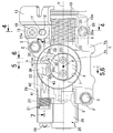
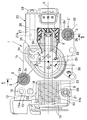
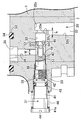
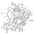
- the throttle body 1 is formed by processing a throttle body semi-finished product 01 (see FIGS. 10 and 11) molded by a mold apparatus of the present invention described later.
- the throttle body 1 is made of a light alloy and includes a cylindrical body 1a and a flange 1b that projects from one end of the cylindrical body 1a to the outer periphery.
- the flange portion 1b has a substantially square shape when viewed from the front (see FIG. 3), and a pair of upper and lower first and second fastening bosses 2 and 2 'are formed at one corner of the flange portion 1b.
- An inlet tube 6 connected to the air cleaner is fitted and connected to the outer periphery of the cylindrical portion 1a.
- the stay boss 15, the first bearing boss 9, the return spring 23, and the fully closed stopper boss 20 can be aligned on one side of the flange portion 1b, which can contribute to the compactness of the throttle body 1.
- the stay boss 15 from one side of the flange portion 1b is integrally provided on the outside of the first fastening boss 2 that is arranged so as to partially overlap the cylindrical portion 1a in plan view.
- the projection length of the fully-closed stopper boss 20 aligned with the stay boss 15 from the flange portion 1b can also be kept short, thereby further reducing the throttle body 1 in size. Can contribute.
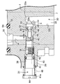
- the measuring hole 34 and the through holes 50, 50... are always arranged so as to be offset from each other along the axial direction of the adjusting valve shaft 43 at any adjustment position of the adjusting valve shaft 43.
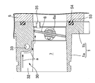
- valve hole 33 communicating with the concave groove 32 is disposed in a direction that is bent at a substantially right angle from the front of the dead end portion 32a of the concave groove 32, and the opening 33a of the valve hole 33 to the concave groove 32 is Since the opening 33a is disposed away from the peripheral edge of the step portion 33a, the inner surface 32b of the groove 32 is formed on the step portion 32c.
- the flowing water droplets flow around the step portion 32c as shown by the arrow a in FIG. 5 and the arrow b in FIG. 6 due to the inertia of the flow, thereby avoiding the opening 33a and preventing the water droplet from entering the valve hole 33. Can do.
- the notch 35 having a notch shape serving as the downstream end of the bypass 30 is formed obliquely above the intake passage 7 on the end face of the flange portion 1b facing the intake pipe 5.
- a water-drop shaped seal groove 53 that opens and surrounds the notch 35 and the intake passage 7 is formed on the end surface of the flange portion 1b.
- the seal groove 53 includes first and second fastening bosses 2 of the flange portion 1b. , 2 ′ are fastened to the intake pipe 5 by the fastening bolts 3, 3, an O-ring 54 that is in close contact with the end surface of the intake pipe 5 is attached.
- the third fully closed stopper boss 20 is provided with a third lower hole 020a for machining the screw hole 20a into which the fully closed stopper bolt 21 is screwed in parallel with the axis X of the intake passage 7.
- a fourth core pin 64d corresponding to the fourth lower hole 015a is connected to one of the first and second main molds 61 and 62 (see FIG. 13).
- a core pin (not shown) corresponding to the hole 2b for inserting the fastening bolts 3, 3 of the first and second fastening bosses 2, 2 ' is provided on one of the first and second main molds 61, 62. are connected.
Landscapes
- Engineering & Computer Science (AREA)
- Mechanical Engineering (AREA)
- Chemical & Material Sciences (AREA)
- Combustion & Propulsion (AREA)
- General Engineering & Computer Science (AREA)
- Manufacturing & Machinery (AREA)
- Control Of Throttle Valves Provided In The Intake System Or In The Exhaust System (AREA)
- Molds, Cores, And Manufacturing Methods Thereof (AREA)
Abstract
Description
1・・・・・スロットルボディ
1a・・・・円胴部
7・・・・・吸気道
8・・・・・スロットル弁
8a・・・・弁軸
9・・・・・第1軸受ボス
9′・・・・第2軸受ボス
09a・・・第1下孔
11・・・・スロットル操作ワイヤ
12・・・・ガイドチューブ
13・・・・ガイドチューブステー
15・・・・ステーボス
15a・・・ねじ孔
015a・・第4下孔
20・・・・全閉ストッパボス
20a・・・ねじ孔
020a・・第3下孔
21・・・・全閉ストッパボルト
25・・・・スロットル開度センサ
26・・・・ケーシング
27・・・・センサ支持ボス
27a・・・ねじ孔
027a・・第2下孔
29・・・・アイドル調整ボス
029a・・第5下孔
31・・・・アイドル調整弁
38・・・・ねじ孔
60・・・・金型装置
61・・・・第1主型
62・・・・第2主型
63・・・・スライド型
64a~64a・・・第1~第5中子ピン
65・・・・ランナ
66・・・・ゲート
67・・・・第1複合型
68・・・・第2複合型
69・・・・主ランナ
70・・・・キャビティ
A・・・・・一方の組
B・・・・・他方の組
X・・・・・吸気道の軸線
Y・・・・・弁軸の軸線
Claims (5)
- 内部を吸気道(7)とする円胴部(1a)と,この円胴部(1a)の両側壁に一体に形成されて,吸気道(7)を開閉するスロットル弁(8)の弁軸(8a)の両端部を支承する第1及び第2軸受ボス(9,9′)と,円胴部(1a)の外側に連結されて,第1軸受ボス(9)の一側方に配置される全閉ストッパボス(20)と,円胴部(1a)の外側に連結されて,第2軸受ボス(9′)の一側方に配置されるセンサ支持ボス(27)とを備え,前記第1及び第2軸受ボス(9,9′)には,前記弁軸(8a)が回転自在に嵌合する軸孔(9a)加工用の第1下孔(09a)が設けられ,前記センサ支持ボス(27)には,第2軸受ボス(9′)に嵌合されるスロットル開度センサ(25)のケーシング(26)をねじ止めするためのねじ孔(27a)加工用の第2下孔(027a)が弁軸(8a)の軸線(Y)と平行に設けられ,前記全閉ストッパボス(20)には,スロットル弁(8)の全閉位置を規制する全閉ストッパボルト(21)が螺合するねじ孔(20a)加工用の第3下孔(020a)が吸気道(7)の軸線(X)と平行に設けられるスロットルボディ半製品(01)を成形する金型装置であって,
前記吸気道(7)の軸線(X)に沿って互いに開閉する第1及び第2主型(61,62)と,これら第1及び第2主型(61,62)の一側面に対して,前記弁軸(8a)の軸線(Y)に沿う方向で開閉すべく第1及び第2主型(61,62)の何れか一方にスライド可能に支持される単一のスライド型(63)とよりなり,
そのスライド型(63)には,前記第1下孔(09a)及び前記第2下孔(027a)にそれぞれ対応する第1中子ピン(64a)及び第2中子ピン(64b)を連設し,
また第1及び第2主型(61,62)の一方には,前記第3下孔(020a)に対応して配置される第3中子ピン(64c)を連設し,
第1主型(61),第2主型(62)及び単一のスライド型(63)間に,前記第1~第3中子ピン(64a)~(64c)を囲んで前記スロットルボディ半製品(01)を成形するキャビティ(70)を形成したことを特徴とする,スロットルボディ半製品の成形用金型装置。 - 請求項1記載のスロットルボディ半製品の成形用金型装置において,
スロットルボディ半製品(01)は,第1軸受ボス(9)を挟んで前記全閉ストッパボス(20)と反対側で円胴部(1a)に連結されるステーボス(15)を備え,このステーボス(15)には,スロットル操作ワイヤ(11)のガイドチューブ(12)の端部を支持するガイドチューブステー(13)をねじ止めするためのねじ孔(15a)加工用の第4下孔(015a)が吸気道(7)の軸線(X)と平行に設けられており,
第1及び第2主型(61,62)の一方には,前記第4下孔(015a)に対応する第4中子ピン(64d)を連設し,
第1主型(61),第2主型(62)及び単一のスライド型(63)間に,前記第4中子ピン(64d)を囲んで前記スロットルボディ半製品(01)を成形するキャビティ(70)を形成したことを特徴とする,スロットルボディ半製品の成形用金型装置。 - 請求項1記載のスロットルボディ半製品の成形用金型装置において,
スロットルボディ半製品(01)は,第2軸受ボス(9′)の一側方に配置されて円胴部(1a)に連結されるアイドル調整ボス(29)を備え,このアイドル調整ボス(29)には,アイドル調整弁(31)を螺合するねじ孔(38)加工用の第5下孔(029a)が弁軸(8a)の軸線(Y)と平行に設けられており,
スライド型(63)に,前記第5下孔(029a)に対応する第5中子ピン(64e)を連設し,
第1主型(61),第2主型(62)及び単一のスライド型(63)間に,前記第5中子ピン(64e)を囲んで前記スロットルボディ半製品(01)を成形するキャビティ(70)を形成したことを特徴とする,スロットルボディ半製品の成形用金型装置。 - 請求項1~3の何れかに記載のスロットルボディ半製品の成形用金型装置において,
少なくとも2組(A,B)の第1,第2主型(61,62)及びスライド型(63)間に共通のランナ(65)を設けると共に,このランナ(65)を挟んで,一方の組の第1,第2主型(61,62)及びスライド型(63)と,他方の組の第1,第2主型(61,62)及びスライド型(63)とを点対称に配置し,
一方の組の第1主型(61)と他方の組の第2主型(62)とを一体に形成して第1複合型(67)を構成し,
また一方の組の第2主型(62)と他方の組の第1主型(61)とを一体に形成して第2複合型(68)を構成したことを特徴とする,スロットルボディ半製品の成形用金型装置。 - 請求項1~4の何れかに記載のスロットルボディ半製品の成形用金型装置において,
前記キャビティ(70)を,これが前記第1中子ピン(64a)の先端面を覆うように形成し,前記第1及び第2主型(61,62)には,ランナ(65)と,このランナ(65)を,前記キャビティ(70)の,前記第1中子ピン(64a)の先端面を受容する部分(70d)に連通するゲート(66)とを形成したことを特徴とする,スロットルボディ半製品の成形用金型装置。
Priority Applications (2)
| Application Number | Priority Date | Filing Date | Title |
|---|---|---|---|
| BRPI1009776A BRPI1009776B1 (pt) | 2009-04-27 | 2010-04-14 | dispositivo de molde para moldar produto semiacabado de corpo de acelerador |
| CN2010800185455A CN102413965B (zh) | 2009-04-27 | 2010-04-14 | 节气门体半成品的成形用模具装置 |
Applications Claiming Priority (2)
| Application Number | Priority Date | Filing Date | Title |
|---|---|---|---|
| JP2009108166A JP2010255572A (ja) | 2009-04-27 | 2009-04-27 | スロットルボディ半製品の成形用金型装置 |
| JP2009-108166 | 2009-04-27 |
Publications (1)
| Publication Number | Publication Date |
|---|---|
| WO2010125914A1 true WO2010125914A1 (ja) | 2010-11-04 |
Family
ID=43032067
Family Applications (1)
| Application Number | Title | Priority Date | Filing Date |
|---|---|---|---|
| PCT/JP2010/056659 Ceased WO2010125914A1 (ja) | 2009-04-27 | 2010-04-14 | スロットルボディ半製品の成形用金型装置 |
Country Status (4)
| Country | Link |
|---|---|
| JP (1) | JP2010255572A (ja) |
| CN (1) | CN102413965B (ja) |
| BR (1) | BRPI1009776B1 (ja) |
| WO (1) | WO2010125914A1 (ja) |
Cited By (4)
| Publication number | Priority date | Publication date | Assignee | Title |
|---|---|---|---|---|
| US10265891B2 (en) | 2014-12-03 | 2019-04-23 | Zimmer, Inc. | Antioxidant-infused ultra high molecular weight polyethylene |
| CN111992673A (zh) * | 2020-09-10 | 2020-11-27 | 山西卡耐夫管业股份有限公司 | 垂直造型机下滤网装置 |
| CN114378273A (zh) * | 2022-01-20 | 2022-04-22 | 厦门市佳嘉达机械有限公司 | 一种压铸模具、压铸装置及超高速压铸方法 |
| JP7539288B2 (ja) | 2020-10-07 | 2024-08-23 | 日立Astemo株式会社 | 吸気制御装置の製造方法 |
Families Citing this family (5)
| Publication number | Priority date | Publication date | Assignee | Title |
|---|---|---|---|---|
| KR102402078B1 (ko) | 2015-06-30 | 2022-05-26 | 엘지전자 주식회사 | 의류처리장치 |
| JP6434621B2 (ja) * | 2015-07-01 | 2018-12-05 | 本田技研工業株式会社 | 鋳造装置 |
| CN105382203B (zh) * | 2015-10-29 | 2017-10-31 | 共享铸钢有限公司 | 蒸汽轮机阀壳铸件的铸造方法 |
| JP6676804B1 (ja) * | 2019-03-29 | 2020-04-08 | 株式会社ケーヒン | 吸気制御装置 |
| KR102562915B1 (ko) * | 2021-06-28 | 2023-08-04 | 주식회사 신성하이텍 | 생산성을 향상시킨 다이캐스팅을 이용한 차량용 스로틀바디의 제조방법 및 그에 의해 제조된 스로틀바디 |
Citations (3)
| Publication number | Priority date | Publication date | Assignee | Title |
|---|---|---|---|---|
| JP2001074156A (ja) * | 1999-09-07 | 2001-03-23 | Nissan Motor Co Ltd | 空気流量制御装置の製造方法およびその成形金型 |
| JP2005113717A (ja) * | 2003-10-03 | 2005-04-28 | Keihin Corp | 燃料噴射弁付きスロットルボディ及びスロットルボディ成形用金型装置 |
| JP2007239560A (ja) * | 2006-03-07 | 2007-09-20 | Mikuni Corp | エンジン制御装置および二輪車 |
Family Cites Families (5)
| Publication number | Priority date | Publication date | Assignee | Title |
|---|---|---|---|---|
| DE69716143T2 (de) * | 1996-01-12 | 2003-07-10 | Topy Kogyo K.K., Tokio/Tokyo | Verfahren und Vorrichtung zum Giessen eines Leichtmetallrad |
| JP3857550B2 (ja) * | 2001-07-26 | 2006-12-13 | アスモ株式会社 | ギアハウジングの製造方法及びこれに用いられる金型 |
| DE10329484A1 (de) * | 2003-07-01 | 2005-01-27 | Robert Bosch Gmbh | Verfahren zur Herstellung einer Drosselklappeneinheit im Zweikomponentenspritz-Giessverfahren |
| JP4103721B2 (ja) * | 2003-08-01 | 2008-06-18 | 株式会社デンソー | 内燃機関用スロットル装置の成形方法 |
| JP4211574B2 (ja) * | 2003-11-07 | 2009-01-21 | 株式会社デンソー | 内燃機関用スロットル装置の成形方法 |
-
2009
- 2009-04-27 JP JP2009108166A patent/JP2010255572A/ja active Pending
-
2010
- 2010-04-14 CN CN2010800185455A patent/CN102413965B/zh active Active
- 2010-04-14 BR BRPI1009776A patent/BRPI1009776B1/pt active IP Right Grant
- 2010-04-14 WO PCT/JP2010/056659 patent/WO2010125914A1/ja not_active Ceased
Patent Citations (3)
| Publication number | Priority date | Publication date | Assignee | Title |
|---|---|---|---|---|
| JP2001074156A (ja) * | 1999-09-07 | 2001-03-23 | Nissan Motor Co Ltd | 空気流量制御装置の製造方法およびその成形金型 |
| JP2005113717A (ja) * | 2003-10-03 | 2005-04-28 | Keihin Corp | 燃料噴射弁付きスロットルボディ及びスロットルボディ成形用金型装置 |
| JP2007239560A (ja) * | 2006-03-07 | 2007-09-20 | Mikuni Corp | エンジン制御装置および二輪車 |
Cited By (4)
| Publication number | Priority date | Publication date | Assignee | Title |
|---|---|---|---|---|
| US10265891B2 (en) | 2014-12-03 | 2019-04-23 | Zimmer, Inc. | Antioxidant-infused ultra high molecular weight polyethylene |
| CN111992673A (zh) * | 2020-09-10 | 2020-11-27 | 山西卡耐夫管业股份有限公司 | 垂直造型机下滤网装置 |
| JP7539288B2 (ja) | 2020-10-07 | 2024-08-23 | 日立Astemo株式会社 | 吸気制御装置の製造方法 |
| CN114378273A (zh) * | 2022-01-20 | 2022-04-22 | 厦门市佳嘉达机械有限公司 | 一种压铸模具、压铸装置及超高速压铸方法 |
Also Published As
| Publication number | Publication date |
|---|---|
| CN102413965A (zh) | 2012-04-11 |
| CN102413965B (zh) | 2013-12-04 |
| BRPI1009776A2 (pt) | 2016-03-15 |
| BRPI1009776B1 (pt) | 2018-05-08 |
| JP2010255572A (ja) | 2010-11-11 |
Similar Documents
| Publication | Publication Date | Title |
|---|---|---|
| WO2010125914A1 (ja) | スロットルボディ半製品の成形用金型装置 | |
| JP5147768B2 (ja) | エンジンの吸気制御装置 | |
| US7694662B2 (en) | Bypass-intake-flow control apparatus | |
| CN104136734B (zh) | 废气分配器 | |
| JP2003176730A (ja) | 絞りフラップユニットの製造方法 | |
| WO2010110212A1 (ja) | エンジンの吸気制御装置 | |
| EP1508687B1 (en) | Intake passage of an internal combustion engine | |
| EP1304461A1 (en) | Intake manifold for internal combustion engine, and multiple and independent intake passages | |
| CN102812255B (zh) | 带有阀机构的涡轮增压器壳体及其制造方法 | |
| JP5342287B2 (ja) | エンジンのアイドル調整装置 | |
| ITRM20080399A1 (it) | Dispositivo di controllo di immissione per il motore termico di un veicolo. | |
| JP5342288B2 (ja) | エンジンの吸気制御装置 | |
| WO2005086635A2 (en) | Air management systems | |
| JP5527583B2 (ja) | 内燃機関用吸気装置 | |
| US6681804B2 (en) | Device for controlling the output of rotary compressors | |
| JP2006029300A (ja) | スロットル弁 | |
| CN117515203A (zh) | 球阀 | |
| JP3754564B2 (ja) | スロットル装置 | |
| CN101253325A (zh) | 发动机用进气装置 | |
| JP3695053B2 (ja) | エンジンのバルブボディ構造及びその製造方法 | |
| JP5858819B2 (ja) | Egrクーラバイパスバルブ | |
| JP2005226594A (ja) | 内燃機関の多連スロットル装置 | |
| JPH1137319A (ja) | 流路切替バルブ構造及び流路切替バルブ構造体の製造方法 | |
| JP2007332789A (ja) | 吸気絞り装置 | |
| JP2005233146A (ja) | 電子スロットル装置 |
Legal Events
| Date | Code | Title | Description |
|---|---|---|---|
| WWE | Wipo information: entry into national phase |
Ref document number: 201080018545.5 Country of ref document: CN |
|
| 121 | Ep: the epo has been informed by wipo that ep was designated in this application |
Ref document number: 10769613 Country of ref document: EP Kind code of ref document: A1 |
|
| WWE | Wipo information: entry into national phase |
Ref document number: 7843/CHENP/2011 Country of ref document: IN |
|
| NENP | Non-entry into the national phase |
Ref country code: DE |
|
| 122 | Ep: pct application non-entry in european phase |
Ref document number: 10769613 Country of ref document: EP Kind code of ref document: A1 |
|
| REG | Reference to national code |
Ref country code: BR Ref legal event code: B01A Ref document number: PI1009776 Country of ref document: BR |
|
| ENP | Entry into the national phase |
Ref document number: PI1009776 Country of ref document: BR Kind code of ref document: A2 Effective date: 20110914 |