WO2010109971A1 - 弁開閉時期制御装置 - Google Patents
弁開閉時期制御装置 Download PDFInfo
- Publication number
- WO2010109971A1 WO2010109971A1 PCT/JP2010/052076 JP2010052076W WO2010109971A1 WO 2010109971 A1 WO2010109971 A1 WO 2010109971A1 JP 2010052076 W JP2010052076 W JP 2010052076W WO 2010109971 A1 WO2010109971 A1 WO 2010109971A1
- Authority
- WO
- WIPO (PCT)
- Prior art keywords
- fluid
- pressure
- chamber
- phase
- receiving surface
- Prior art date
Links
Images


Classifications
-
- F—MECHANICAL ENGINEERING; LIGHTING; HEATING; WEAPONS; BLASTING
- F01—MACHINES OR ENGINES IN GENERAL; ENGINE PLANTS IN GENERAL; STEAM ENGINES
- F01L—CYCLICALLY OPERATING VALVES FOR MACHINES OR ENGINES
- F01L1/00—Valve-gear or valve arrangements, e.g. lift-valve gear
- F01L1/34—Valve-gear or valve arrangements, e.g. lift-valve gear characterised by the provision of means for changing the timing of the valves without changing the duration of opening and without affecting the magnitude of the valve lift
- F01L1/344—Valve-gear or valve arrangements, e.g. lift-valve gear characterised by the provision of means for changing the timing of the valves without changing the duration of opening and without affecting the magnitude of the valve lift changing the angular relationship between crankshaft and camshaft, e.g. using helicoidal gear
- F01L1/3442—Valve-gear or valve arrangements, e.g. lift-valve gear characterised by the provision of means for changing the timing of the valves without changing the duration of opening and without affecting the magnitude of the valve lift changing the angular relationship between crankshaft and camshaft, e.g. using helicoidal gear using hydraulic chambers with variable volume to transmit the rotating force
-
- F—MECHANICAL ENGINEERING; LIGHTING; HEATING; WEAPONS; BLASTING
- F01—MACHINES OR ENGINES IN GENERAL; ENGINE PLANTS IN GENERAL; STEAM ENGINES
- F01L—CYCLICALLY OPERATING VALVES FOR MACHINES OR ENGINES
- F01L1/00—Valve-gear or valve arrangements, e.g. lift-valve gear
- F01L1/02—Valve drive
- F01L1/022—Chain drive
-
- F—MECHANICAL ENGINEERING; LIGHTING; HEATING; WEAPONS; BLASTING
- F01—MACHINES OR ENGINES IN GENERAL; ENGINE PLANTS IN GENERAL; STEAM ENGINES
- F01L—CYCLICALLY OPERATING VALVES FOR MACHINES OR ENGINES
- F01L1/00—Valve-gear or valve arrangements, e.g. lift-valve gear
- F01L1/34—Valve-gear or valve arrangements, e.g. lift-valve gear characterised by the provision of means for changing the timing of the valves without changing the duration of opening and without affecting the magnitude of the valve lift
- F01L1/344—Valve-gear or valve arrangements, e.g. lift-valve gear characterised by the provision of means for changing the timing of the valves without changing the duration of opening and without affecting the magnitude of the valve lift changing the angular relationship between crankshaft and camshaft, e.g. using helicoidal gear
- F01L1/3442—Valve-gear or valve arrangements, e.g. lift-valve gear characterised by the provision of means for changing the timing of the valves without changing the duration of opening and without affecting the magnitude of the valve lift changing the angular relationship between crankshaft and camshaft, e.g. using helicoidal gear using hydraulic chambers with variable volume to transmit the rotating force
- F01L2001/3445—Details relating to the hydraulic means for changing the angular relationship
- F01L2001/34453—Locking means between driving and driven members
- F01L2001/34469—Lock movement parallel to camshaft axis
-
- F—MECHANICAL ENGINEERING; LIGHTING; HEATING; WEAPONS; BLASTING
- F01—MACHINES OR ENGINES IN GENERAL; ENGINE PLANTS IN GENERAL; STEAM ENGINES
- F01L—CYCLICALLY OPERATING VALVES FOR MACHINES OR ENGINES
- F01L1/00—Valve-gear or valve arrangements, e.g. lift-valve gear
- F01L1/34—Valve-gear or valve arrangements, e.g. lift-valve gear characterised by the provision of means for changing the timing of the valves without changing the duration of opening and without affecting the magnitude of the valve lift
- F01L1/344—Valve-gear or valve arrangements, e.g. lift-valve gear characterised by the provision of means for changing the timing of the valves without changing the duration of opening and without affecting the magnitude of the valve lift changing the angular relationship between crankshaft and camshaft, e.g. using helicoidal gear
- F01L1/3442—Valve-gear or valve arrangements, e.g. lift-valve gear characterised by the provision of means for changing the timing of the valves without changing the duration of opening and without affecting the magnitude of the valve lift changing the angular relationship between crankshaft and camshaft, e.g. using helicoidal gear using hydraulic chambers with variable volume to transmit the rotating force
- F01L2001/3445—Details relating to the hydraulic means for changing the angular relationship
- F01L2001/34453—Locking means between driving and driven members
- F01L2001/34473—Lock movement perpendicular to camshaft axis
-
- F—MECHANICAL ENGINEERING; LIGHTING; HEATING; WEAPONS; BLASTING
- F01—MACHINES OR ENGINES IN GENERAL; ENGINE PLANTS IN GENERAL; STEAM ENGINES
- F01L—CYCLICALLY OPERATING VALVES FOR MACHINES OR ENGINES
- F01L1/00—Valve-gear or valve arrangements, e.g. lift-valve gear
- F01L1/34—Valve-gear or valve arrangements, e.g. lift-valve gear characterised by the provision of means for changing the timing of the valves without changing the duration of opening and without affecting the magnitude of the valve lift
- F01L1/344—Valve-gear or valve arrangements, e.g. lift-valve gear characterised by the provision of means for changing the timing of the valves without changing the duration of opening and without affecting the magnitude of the valve lift changing the angular relationship between crankshaft and camshaft, e.g. using helicoidal gear
- F01L1/3442—Valve-gear or valve arrangements, e.g. lift-valve gear characterised by the provision of means for changing the timing of the valves without changing the duration of opening and without affecting the magnitude of the valve lift changing the angular relationship between crankshaft and camshaft, e.g. using helicoidal gear using hydraulic chambers with variable volume to transmit the rotating force
- F01L2001/3445—Details relating to the hydraulic means for changing the angular relationship
- F01L2001/34453—Locking means between driving and driven members
- F01L2001/34476—Restrict range locking means
-
- F—MECHANICAL ENGINEERING; LIGHTING; HEATING; WEAPONS; BLASTING
- F01—MACHINES OR ENGINES IN GENERAL; ENGINE PLANTS IN GENERAL; STEAM ENGINES
- F01L—CYCLICALLY OPERATING VALVES FOR MACHINES OR ENGINES
- F01L1/00—Valve-gear or valve arrangements, e.g. lift-valve gear
- F01L1/34—Valve-gear or valve arrangements, e.g. lift-valve gear characterised by the provision of means for changing the timing of the valves without changing the duration of opening and without affecting the magnitude of the valve lift
- F01L1/344—Valve-gear or valve arrangements, e.g. lift-valve gear characterised by the provision of means for changing the timing of the valves without changing the duration of opening and without affecting the magnitude of the valve lift changing the angular relationship between crankshaft and camshaft, e.g. using helicoidal gear
- F01L1/3442—Valve-gear or valve arrangements, e.g. lift-valve gear characterised by the provision of means for changing the timing of the valves without changing the duration of opening and without affecting the magnitude of the valve lift changing the angular relationship between crankshaft and camshaft, e.g. using helicoidal gear using hydraulic chambers with variable volume to transmit the rotating force
- F01L2001/3445—Details relating to the hydraulic means for changing the angular relationship
- F01L2001/34483—Phaser return springs
Definitions
- the present invention relates to a valve timing control device for controlling the opening and closing timings of an intake valve and an exhaust valve of an internal combustion engine.
- valve timing control device has been installed on one end of a camshaft, which can change the opening and closing timing of an intake valve or an exhaust valve in accordance with the operating state of an internal combustion engine.
- valve timing control system of this type is a valve timing control system for transmitting engine rotational power from a crankshaft to a camshaft by a power transmission means such as a timing chain.
- a power transmission means such as a timing chain.
- the receiving hole and the retracting hole are synchronized, and the advancing chamber is supplied with the fluid through the first fluid passage, or the retarding chamber is supplied with the fluid through the second fluid passage.
- the third fluid passage communicates with the first fluid passage or the second fluid passage when the positions of the receiving hole and the withdrawal hole are synchronized, and when the receiving hole and the withdrawal hole are not synchronized, the third fluid passage serves as the first fluid passage or As a configuration in which communication with the second fluid passage is blocked, a technique is disclosed that suppresses the generation of noise due to flapping within the retraction hole of the lock pin due to pressure fluctuation and the wear of the lock pin (for example, , Patent Document 2).
- the relative phase between the rotary shaft (camshaft and internal rotor) and the rotation transmission member (external rotor) in the maximum advance state where the volume of the retardation chamber is minimized by the vanes and the volume of the advance chamber by the vane The intermediate relative phase between the relative phases in the minimum maximum retardation state, and the phase when the rotational shaft and the rotation transmitting member have a predetermined relative phase when the internal combustion engine is in startable valve opening / closing timing
- the holding mechanism (lock pin, spring) holds the relative phase of the rotation shaft and the rotation transmission member, and retards the predetermined relative phase of the rotation shaft relative to the rotation transmission member when the internal combustion engine is stopped and started.
- a relative rotation restriction means (engagement pin, spring, engagement groove) for restricting relative rotation to the gear is provided, and generation of a hammering noise by the vane at the time of starting of the internal combustion engine and start failure are reliably prevented.
- Technology to expand the variable control area is disclosed (e.g., see Patent Document 3).
- JP 2000-2104 A Unexamined-Japanese-Patent No. 11-132015 gazette Japanese Patent Application Laid-Open No. 11-311107
- Patent Document 1 when the configuration of Patent Document 1 is applied to a valve timing control device that locks at a predetermined phase between the most advanced phase and the most retarded phase, the valve timing control device operates when the internal combustion engine starts. Since the advance hydraulic pressure or the retard hydraulic pressure is simultaneously applied to release the lock pin at the same time as the oil is fed, there is a possibility that the lock pin may be released when it is desired to hold the intermediate phase.
- Patent Document 2 when the configuration of Patent Document 2 is applied to a valve timing control device that locks at a predetermined phase between the most advanced phase and the most retarded phase, one side oil pressure of the advanced oil pressure or the retarded oil pressure is used.
- the lock pin straddles the receiving hole during operation from the advancing phase to the retarding phase or from the retarding phase to the advancing phase due to the unlocking configuration, there is a fear that the lock pin may be misinserted in the receiving hole. was there.
- the valve timing control device since the release oil path of the lock pin that locks in the middle phase is a dedicated circuit separate from the advance oil pressure and the retard oil pressure, the valve timing control device operates In addition to the hydraulic pressure control valve, a hydraulic pressure control valve or a hydraulic pressure switching valve for releasing the lock pin is required, which may lead to the deterioration of the system mountability, the cost increase, and the mass increase.
- valve timing control device the valve timing can be reliably locked to a predetermined intermediate phase with a simple configuration without inadvertently operating the lock pin with advance hydraulic pressure or retard hydraulic pressure when starting the internal combustion engine It is an object to provide a control device.
- the first technical means taken to solve the above problems is an inner circumferential member integrally rotating with a valve opening / closing camshaft that is rotatably assembled to a cylinder head of an internal combustion engine, and an integral with the inner circumferential member.
- Fluid pressure chamber a first fluid passage for supplying and discharging a fluid to and from the advancing chamber, a second fluid passage for supplying and discharging a fluid to the retarding chamber, and the inner circumferential member and the outer circumferential member
- a phase holding mechanism for holding the relative phase at a predetermined phase between the most advanced phase and the most retarded phase; and the advance chamber or the advanced chamber through the first fluid passage or the second fluid passage.
- a fluid supply device for supplying a fluid to the retardation chamber; And a fluid control valve for switching a fluid passage to the first fluid passage or the second fluid passage and controlling a fluid supply amount, and the phase control mechanism causes the fluid control valve to start the fluid supply.
- the fluid pressure of any one of the first fluid passage and the second fluid passage is released from the holding state of the relative phase and the holding state of the relative phase is released, the first fluid passage and the The release state is maintained by fluid pressure acting from at least one of the two fluid passages.
- the second technical means is the first technical means, wherein the phase holding mechanism, the phase holding mechanism is provided on a restrictor that restricts the relative phase, and the inner circumferential member is slid on the restrictor.
- the restriction is constituted by an accommodation hole which is accommodated movably, a reception hole which is provided in the outer peripheral member and into which a tip end of the restriction body is inserted, and an urging member which urges the restriction body in the direction of the outer peripheral member.
- the body includes a first pressure receiving surface for receiving either the fluid pressure of the advancing chamber or the fluid pressure of the retarding chamber, the fluid pressure of the advancing chamber, and the fluid pressure of the retarding chamber.
- a second pressure receiving surface for receiving the other, and the supply of fluid from the fluid supply device may be performed from the one of the advancing chamber and the retarding chamber from the advancing chamber and the retarding chamber.
- the pressure chamber is switched to the other side, the fluid pressure and the pressure of the advance chamber are applied to the second pressure receiving surface.
- the other one of the fluid pressure in the retarded angle chamber is that the holding state of the act said phase holding mechanism is released.
- a third technical means is the second technical means, wherein the fluid pressure of the advancing chamber to the first pressure receiving surface and the retarding chamber after the holding state of the phase holding mechanism is released.
- the fluid pressure of any one of the fluid pressure and the fluid pressure of the advance chamber and the fluid pressure of the retard chamber on the second pressure receiving surface are selected from the first pressure receiving surface and the retarding chamber after the holding state of the phase holding mechanism.
- the release of the holding state of the phase holding mechanism is maintained by at least one of the actions.
- a fourth technical means is the first technical means, wherein the phase holding mechanism is provided with a restricting body for restricting the relative phase, and the inner circumferential member so as to slidably accommodate the restricting body. It is comprised from a hole, The receiving hole which is provided in the said outer periphery member and which the tip of the above-mentioned regulation body inserts, and the energizing member which biases the above-mentioned regulation body in the direction of the above-mentioned outer periphery member.
- a first pressure receiving surface for receiving either the fluid pressure of the chamber or the fluid pressure of the retarding chamber, and the fluid pressure of the advancing chamber or the fluid pressure of the retarding chamber; It has two pressure receiving surfaces, and the first pressure receiving surface and the second pressure receiving surface have different pressure receiving areas.
- a fifth technical means wherein the fluid supply device is rotationally driven by transmitting the torque of a crankshaft of the internal combustion engine, and the fluid is idled during the idling operation of the internal combustion engine
- the fluid supplied from the feeding device acts on the pressure receiving surface having a smaller pressure receiving area among the first pressure receiving surface and the second pressure receiving surface, thereby pressing the regulating body in a direction to oppose the biasing force of the biasing member.
- the pressing force is smaller than the biasing force of the biasing member.
- a sixth technical means is the fifth technical means, wherein an idling pressure area of the first pressure receiving surface and the second pressure receiving surface of the fluid supplied from the fluid supply device during idling operation of the internal combustion engine
- the pressing force for pressing the restricting body in the direction to oppose the biasing force of the biasing member by acting on the side of the pressure receiving surface having a large value is larger than the biasing force of the biasing member.
- a seventh technical means according to any one of the fourth to sixth technical means, wherein the fluid supply from the fluid supply device is either one of the advancing chamber and the retarding chamber.
- the fluid pressure of the advance chamber or the fluid pressure of the retard chamber acts on the second pressure receiving surface. And the holding state of the phase holding mechanism is released.
- An eighth technical means according to the seventh technical means, wherein the fluid pressure of the advancing chamber to the first pressure receiving surface and the retarding chamber after the holding state of the phase holding mechanism is released.
- the fluid pressure of any one of the fluid pressure and the fluid pressure of the advance chamber and the fluid pressure of the retard chamber on the second pressure receiving surface are maintained by at least one of the actions.
- the phase holding mechanism releases the relative phase holding state only by the fluid pressure of either one of the first fluid passage and the second fluid passage where the fluid control valve starts supplying the fluid.
- the lock pin is not inadvertently erroneously operated by the advance oil pressure or the retard oil pressure supplied from the fluid supply device which starts operation simultaneously with the start of the internal combustion engine, and it is possible to reliably hold the predetermined intermediate phase with a simple configuration. it can.
- the released state is maintained by the fluid pressure acting from at least one of the first fluid passage and the second fluid passage, so that the advancing phase to the retarding phase, or When the lock pin straddles the receiving hole during the operation from the retardation phase to the advancing phase, the lock pin can be prevented from being misinserted into the receiving hole.
- the phase holding mechanism includes a restricting body for restricting relative phase, a receiving hole provided in the inner circumferential member for slidably receiving the restricting body, and a receiving hole provided in the outer circumferential member with the tip of the restricting body fitted therein.
- a biasing member biasing the regulating body in the direction of the outer peripheral member, wherein the regulating body is a first pressure receiving surface that receives either the fluid pressure of the advancing chamber or the fluid pressure of the retarding chamber And a second pressure receiving surface for receiving the other of the fluid pressure of the advancing chamber and the fluid pressure of the retarding chamber, and the supply of fluid from the fluid supply device is performed by the advancing chamber and the retarding chamber.
- either one of the advancing chambers and the retarding chamber is switched to the other, either the fluid pressure of the advancing chamber or the fluid pressure of the retarding chamber acts on the second pressure receiving surface. Since the holding state of the phase holding mechanism is released, the fluid pin control valve or the oil pressure switching valve is not necessary. Becomes, the system mountability deterioration, cost can be suppressed mass up.
- the action of the fluid pressure of either the fluid pressure of the advancing chamber or the fluid pressure of the retarding chamber to the first pressure receiving surface, and the second pressure receiving At least one of the action of the fluid pressure of the advancing chamber and the fluid pressure of the retarding chamber on the surface is configured to maintain the release of the holding state of the phase holding mechanism. Because of this, it is possible to maintain the released state of phase holding with a simple configuration.
- the first pressure receiving surface and the second pressure receiving surface may be configured to have different pressure receiving areas. For example, when the fluid pressure is applied to the side having the large pressure receiving area among the first pressure receiving surface and the second pressure receiving surface to release the restriction of the inner circumferential member and the outer circumferential member by the regulating body, In this case, it is possible to prevent the restriction from being released by the restriction body. In addition, even if it is desired to restrict the inner circumferential member and the outer circumferential member by the regulating body while applying fluid pressure to the side having the large pressure receiving area among the first pressure receiving surface and the second pressure receiving surface, the fluid pressure is less than a predetermined fluid pressure. Regulation by the regulatory body.
- the pressure receiving area is different between the first pressure receiving surface and the second pressure receiving surface, so that the restriction between the first pressure receiving surface or the second pressure receiving surface and the communication between the advancing chamber or the retarding chamber is restricted. It is possible to set restrictions or cancellation by the body.
- the fluid supplied from the fluid supply device acts on the pressure receiving surface having a smaller pressure receiving area among the first pressure receiving surface and the second pressure receiving surface, thereby applying the regulating member to the biasing member.
- the pressing force for pressing in the direction that opposes the force is preferably smaller than the biasing force of the biasing member.
- the fluid supplied from the fluid supply device acts on the pressure receiving surface having the larger pressure receiving area among the first pressure receiving surface and the second pressure receiving surface, thereby adding the regulating member to the biasing member.
- the pressing force for pressing in the direction that opposes the force may be greater than the biasing force of the biasing member.
- FIG. 2 is a longitudinal sectional view showing an embodiment of a valve timing control apparatus according to the present invention (corresponding to a sectional view taken along the line II in FIG. 2).
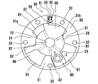
- FIG. 2 is a view on arrow II-II of FIG. 1 showing a state in which a predetermined intermediate relative phase of the rotation shaft and the rotation transmission member is held by the phase holding mechanism.
- FIG. 2 is a cross-sectional view taken along the line III-III in FIG.
- FIG. 3 is a cross-sectional view taken along the line III-III of FIG.
- FIG. 2 is a view on arrow II-II in FIG. 1 showing a maximum retardation state.
- FIG. 2 is a view on arrow II-II in FIG. 1 showing a state of maximum advance angle.
- the present invention controls the valve opening / closing timing of at least one of the intake side and the exhaust side of the internal combustion engine, but the case where it is applied mainly to the intake side will be described here.
- the valve timing control device includes a camshaft 10 rotatably supported by a cylinder head 70 of an internal combustion engine, and an inside integrally assembled to a tip end portion (left end in FIG. 1) thereof.
- the rotary shaft for valve opening and closing consisting of the rotor 20, and the outer rotor 30, the front plate 40, the rear plate 50, and the rear plate 50 integrally mounted on the camshaft 10 and the inner rotor 20 relatively rotatably within a predetermined range.
- Transmission member consisting of a timing sprocket 51 provided in a fixed manner, three vanes 60, 61, 62 integrally formed on the inner rotor 20, and a lock mechanism (phase holding mechanism) 80 assembled to the inner rotor 20.
- the timing sprocket 51 is configured to transmit rotational power in the clockwise direction in FIG. 2 from a crankshaft (not shown) via a crank sprocket and a timing chain.
- the camshaft 10 has a known cam for opening and closing an intake valve (not shown), and internally provided are a retarding passage 11 and an advancing passage 12 extending in the axial direction of the camshaft 10.
- the advance angle passage 12 is formed in a mounting hole for the mounting bolt 16 provided on the camshaft 10, and the radial passage 13 provided on the camshaft 10, the annular groove 14 provided on the cylinder head 70, and the connection passage 72 is connected to the connection port 101 b of the control valve 100.
- the retarding passage 11 is connected to the connection port 101a of the control valve 100 via the passage 15 provided on the camshaft 10, the annular groove 17 provided on the cylinder head 70, and the connecting passage 71.
- the control valve 100 can move the spool 101 axially movably inserted in the housing of the control valve 100 in the left direction of FIG. 1 against the spring 103 by energizing the solenoid 102.
- the supply port 101c connected to the oil pump P driven by the internal combustion engine communicates with the connection port 101a at the time of energization, and the supply port 101c is connected when the connection port 101b communicates with the discharge port 101d.
- the connection port 101a communicates with the port 101b, and the connection port 101a communicates with the discharge port 101d.
- the inner rotor 20 is integrally fixed to the camshaft 10 by a mounting bolt 16, and three vanes 60, 61, 62 are integrally formed. Furthermore, when one of the vanes 61 of the inner rotor 20 synchronizes the relative phase of the camshaft 10 and the inner rotor 20 with the outer rotor 30 at a predetermined phase, the lock pin 81 and the spring of the lock mechanism 80 hold the relative phase.
- a retracting hole 24 for housing 82 is formed in the axial direction of the vane 61. Further, a passage 23 communicating the advance passage 12 with each advance chamber R1 so as to supply and discharge the working oil from the advance passage 12 to the advance chamber R1 partitioned by the three vanes 60, 61, 62.
- annular groove 21 formed on one end face opposite to the tip end face of the camshaft 10 and in communication with the retarded angle passage 11, three passages 22 axially extending from the annular groove 21 to the other end side, and three Each passage 22 is communicated with each retardation chamber R2 so as to supply and discharge the hydraulic oil from the retardation passage 11 through the annular groove 21 and the passage 22 to the retardation chamber R2 partitioned by the vanes 60, 61, 62. And a passage 26.
- the evacuation hole 24 is formed of a large diameter portion on the front plate 40 side and a medium diameter portion smaller than the large diameter portion on the rear plate 50, and the large diameter portion communicates with the advance chamber R1.
- a passage 24b communicating with the retardation chamber R2 is formed in the middle diameter portion 24a.
- the lock pin 81 is axially slidably mounted in the retraction hole 24, and the outer diameter is approximately equal to the large diameter portion of the retraction hole 24 and the middle diameter portion of the retraction hole 24.
- a middle diameter portion and a small diameter portion slightly smaller than the middle diameter portion are provided, and a spring 82 for urging the lock pin 81 toward the rear plate 50 is disposed inside the large diameter portion.
- the small diameter portion is fitted into a receiving hole 29 formed in the axial direction in a sliding surface with the inner rotor 20 of the rear plate 50 at a predetermined phase.
- the step surface between the large diameter portion and the middle diameter portion of the lock pin 81 corresponds to the first pressure receiving surface 81a receiving the hydraulic pressure of the advance chamber R1, and the step surface between the middle diameter portion and the small diameter portion is the retardation chamber. It corresponds to the second pressure receiving surface 81b that receives the hydraulic pressure of R2.
- the engagement groove 28 of the relative rotation restriction mechanism 90 is formed in the circumferential direction on the outer periphery of the vane 60, and the relative phase between the camshaft 10 and the inner rotor 20 and the outer rotor 30 is predetermined.
- the tip of the regulation key 91 described later engages with the engagement groove 28.
- the outer rotor 30 is mounted on the outer periphery of the inner rotor 20 so as to be relatively rotatable within a predetermined range, and the front plate 40 and the rear plate 50 are joined on both sides thereof.
- three projections 31 are formed so as to project radially inward at predetermined circumferential intervals, and the inner peripheral surface of these projections 31 is the inner rotor 20
- the outer rotor 30 is rotatably supported by the inner rotor 20 so as to be in sliding contact with the outer peripheral surface.
- the accommodation groove 35 which accommodates the control key 91 of the relative rotation control mechanism 90 is formed in the radial direction on the outer side of the vane 60.
- the three vanes 60, 61, 62 form a fluid pressure chamber R0 formed between the outer rotor 30, the protrusions 31 of the outer rotor 30, the inner rotor 20, the front plate 40, and the rear plate 50.
- One vane 60 is in contact with the stopper portions 31a and 31b of the circumferential end faces of the pair of projections 31 formed on the external rotor 30, which are divided into the advance chamber R1 and the retard chamber R2.
- the phase (relative rotation amount) adjusted by the valve timing control device is limited.
- the restricting key 91 is assembled slidably in the radial direction in the housing groove 35, and is urged toward the inner rotor 20 by the spring 92.
- the urging force of the spring 92 is set to a predetermined number of rotations. And the centrifugal force generated in the control key 91 is substantially the same.
- the opening / closing timing of the intake valve (not shown) can start the internal combustion engine (the opening / closing timing of the intake valve is slightly It is set to be advanced (intermediate advance)).
- the engagement groove is formed such that the tip end portion of the regulation key 91 can be fitted into the engagement groove 28 when the predetermined relative phase is in the range of the relative phase in the maximum advance state.
- the positions of the housing groove 28 and the housing groove 35 are set.
- the control unit ECU supplies no electricity to the solenoid 102 of the control valve 100, and the hydraulic oil discharged from the oil pump P driven by the internal combustion engine is supplied with the supply port 101c, the connection port 101b, and connection. It is supplied to the advance chamber R1 via the passage 72, the passage 13, the advance passage 12, and the passage 23. However, since the passage 24a communicating the advance chamber R1 with the retraction hole 24 is closed by the large diameter portion of the lock pin 81, no hydraulic pressure is applied to the first pressure receiving surface 81a of the lock pin 81. The small diameter portion of the lock pin 81 is maintained in the state of being fitted into the receiving hole 29 of the rear plate.
- the restriction key 91 of the relative rotation restriction mechanism 90 is accommodated in the accommodation groove 35 by centrifugal force, and the engagement with the engagement groove 28 is released.
- the control unit ECU energizes the solenoid 102 of the control valve 100, the spool 101 moves leftward against the spring 103 to be in the state shown in FIG. 1, and the hydraulic oil discharged from the oil pump P is supplied.
- the retardation chamber R2 is supplied via the port 101c, the connection port 101a, the connection passage 71, the retardation passage 11, the passage 22 and the passage 26.
- the passage 24 b communicating the retardation chamber R ⁇ b> 2 with the retraction hole 24 is open at the small diameter portion of the lock pin 81.
- the hydraulic pressure acting on the retardation chamber R2 acts on the second pressure receiving surface 81b of the lock pin 81 via the passage 24b.
- the lock pin 81 moves in the retraction hole 24 toward the front plate 40, and the small diameter portion of the lock pin 81 is released from the engagement with the receiving hole 29 of the rear plate 50.
- the passage 24a communicating with the advance angle chamber R1 of the large diameter portion of the retraction hole 24 is opened.
- the hydraulic pressure of the advancing chamber R1 acts on the first pressure receiving surface 81a via the passage 24a at the time of advancing operation, and the hydraulic pressure of the retarding chamber R2 at the time of retardation operation is the second via the passage 24b. It acts on the pressure receiving surface 81b. That is, the release state can be maintained at any of the advance oil pressure and the retard oil pressure.
- the hydraulic oil is supplied to the advance chambers R1 through the advance passages 13 and 23 and the delay chambers are formed.
- the hydraulic oil is discharged from R2 through the passages 26 and 22, the retarded passage 11 and the control valve 100, the inner rotor 20 and the vanes 60, 61, 62 move to the outer rotor 30, both plates 40, 50, etc.
- the relative rotation amount (maximum advance angle amount) is in the circumferential direction on the retard side of the protrusion 31 as shown in FIG. It is limited by coming into contact with the stopper portion 31b of the end face.
- the lock by the lock pin 81 is released by the hydraulic pressure of either the advance hydraulic pressure or the retard hydraulic pressure. Further, the restriction key 91 is biased radially outward by centrifugal force, moves against the spring 92, and the tip of the restriction key 91 retracts from the engagement groove 28 into the accommodation groove 35, thereby restricting the restriction key 91. The engagement by the key 91 is released.
- the lock pin 81 is held in the relative phase only by the fluid pressure of the retardation passage 11 at which the control valve 100 starts the supply of hydraulic fluid by the electric signal from the control device ECU. Since it is released, the lock pin 81 is not inadvertently erroneously operated by the advance hydraulic pressure supplied from the oil pump P which starts operation simultaneously with the internal combustion engine start, and the predetermined configuration is reliably held by the simple configuration. be able to.
- the present invention is applied to a valve timing control device that supplies fluid to the advancing chamber R1 when the control valve 100 is not energized and supplies the fluid to the retarding chamber R2 when the control valve 100 is energized.
- the present invention can be similarly applied to a valve timing control device that supplies fluid to the advancing chamber R1 when the control valve 100 is energized and supplies the fluid to the retarding chamber R2 when the control valve 100 is not energized. It is a thing.
- FIGS. 1 to 6 are used for the drawings.
- the first pressure receiving surface 81 a and the second pressure receiving surface 82 b are configured to have different pressure receiving areas. Further, when the hydraulic pressure acts on the second pressure receiving surface 81b, the engagement between the small diameter portion of the lock pin 81 and the receiving hole 29 of the rear plate 50 is released.
- the second pressure receiving surface 81 b is set larger than the first pressure receiving surface 81 a.
- the fluid supplied from the oil pump P (fluid supply device) at the time of idling operation of the internal combustion engine acts on the first pressure receiving surface 81 a to oppose the biasing force of the spring 82 (biasing member)
- the pressing force to be pressed is set to be smaller than the biasing force of the spring 82.
- the pressing force of the fluid supplied from the oil pump P at the time of idling operation of the internal combustion engine acting on the second pressure receiving surface 81 b to oppose the biasing force of the spring 82 (biasing member) It is set larger than the biasing force of.
- the working fluid is supplied from the oil pump P to the lock pin 81 (regulator) during idling operation of the internal combustion engine.
- the relative phase between the inner rotor 20 (inner circumferential member) and the outer rotor 30 (outer circumferential member) can be held by the lock pin 81. Therefore, unlike when the relative phase between the inner circumferential rotor 20 and the outer circumferential rotor 30 is held by the lock pin 81 after the internal combustion engine is stopped, the lock pin 81 is again held even when the relative phase can not be held by the lock pin 81. It is possible to execute an operation to hold the relative phase by.
- the control in the case where the relative phase can not be held by the lock pin 81 moves the relative rotational phase of the inner rotor 20 relative to the outer rotor 30 to a predetermined intermediate phase.
- the hydraulic pressure is supplied to the advance oil chamber R1 and moved to a predetermined intermediate phase
- the small diameter portion of the lock pin 81 is engaged with the receiving hole 29 of the rear plate 50 as it is.
- the hydraulic pressure acts on the second pressure receiving surface 81b and is in a retracted state, so the small diameter portion of the lock pin 81 Are not engaged with the receiving holes 29 of the rear plate 50.
- the hydraulic pressure acts on the first pressure receiving surface 81a by the control valve 100 (fluid control valve) performing control to switch the hydraulic pressure to be supplied from the retarding oil chamber R2 to the advancing oil chamber R1.
- the smaller diameter portion of the lock pin 81 is engaged with the receiving hole 29 of the rear plate 50 because the biasing force of the spring 82 is greater than the pressing force acting on the one pressure receiving surface 81 a.
- the engagement of the lock pin 81 can be released by applying the hydraulic pressure to the second pressure receiving surface 81b. Therefore, even if the pressure receiving area of the first pressure receiving surface 81a is set so as to avoid the failure state in which the relative phase can not be held by the lock pin 81, the relative phase can not be released by the lock pin 81 reversely. Can be prevented.
- regulation key 91 was constituted so that it might get out to and return to vane 60 from exterior rotor 30, it is not restricted to this.
- the restriction key may be configured to move back and forth from the protrusion 31 to the inner rotor 20.
- the present invention is applicable to a valve timing control device that controls the opening and closing of intake and exhaust valves of an internal combustion engine.
Landscapes
- Engineering & Computer Science (AREA)
- Mechanical Engineering (AREA)
- General Engineering & Computer Science (AREA)
- Valve Device For Special Equipments (AREA)
Abstract
Description
また、第二受圧面81bに作動油圧が作用すると、ロックピン81の小径部とリアプレート50の受容孔29との係合が解除されるよう構成されている。
11 遅角通路(第二流体通路)
12 進角通路(第一流体通路)
20 内部ロータ(内周部材)
24 退避孔(収容孔)
29 受容孔
30 外部ロータ(外周部材)
35 収容溝
40 フロントプレート(外周部材)
50 リアプレート(外周部材)
60、61、62 ベーン
70 シリンダヘッド
80 ロック機構(位相保持機構)
81 ロックピン(規制体)
81a 第一受圧面
81b 第二受圧面
82 スプリング(付勢部材)
100 制御弁(流体制御弁)
P オイルポンプ(流体供給装置)
R0 流体圧室
R1 進角用室
R2 遅角用室
Claims (8)
- 内燃機関のシリンダヘッドに回転自在に組付けられる弁開閉用のカムシャフトと一体回転する内周部材と、
前記内周部材と一体回転するベーンと、
前記内周部材と相対回転する外周部材と、
前記内周部材と前記外周部材との間に位置し、前記ベーンによって進角用室と遅角用室とに二分される複数の流体圧室と、
前記進角用室に流体を給排する第一流体通路と、
前記遅角用室に流体を給排する第二流体通路と、
前記内周部材と前記外周部材との相対位相を、最進角位相と最遅角位相との間の所定の位相に保持する位相保持機構と、
前記第一流体通路または前記第二流体通路を介して、前記進角用室または前記遅角用室に流体を供給する流体供給装置と、
前記流体供給装置から吐出された流体の通路を前記第一流体通路または前記第二流体通路に切替えるとともに、流体の供給量を制御する流体制御弁と、を備え、
前記位相保持機構は、前記流体制御弁が流体の供給を開始する前記第一流体通路及び前記第二流体通路のいずれか一方の流体圧力により前記相対位相の保持状態が解除され、前記相対位相の保持状態が解除された後に、前記第一流体通路及び前記第二流体通路のうち少なくともいずれかから作用する流体圧力により解除状態が維持されることを特徴とする弁開閉時期制御装置。 - 請求項1において、
前記位相保持機構が、前記相対位相を規制する規制体と、前記内周部材に設けられ前記規制体を摺動可能に収容する収容孔と、前記外周部材に設けられ前記規制体の先端が嵌入する受容孔と、前記規制体を前記外周部材方向に付勢する付勢部材と、から構成され、
前記規制体は、前記進角用室の流体圧及び前記遅角用室の流体圧のいずれか一方を受ける第一受圧面と、前記進角用室の流体圧及び前記遅角用室の流体圧のいずれか他方を受ける第二受圧面とを有し、
前記流体供給装置からの流体の供給が、前記進角用室及び前記遅角用室のいずれか一方から前記進角用室及び前記遅角用室のいずれか他方に切り替わると、前記第二受圧面に前記進角用室の流体圧及び前記遅角用室の流体圧のいずれか他方が作用して前記位相保持機構の保持状態が解除されることを特徴とする弁開閉時期制御装置。 - 請求項2において、
前記位相保持機構の保持状態が解除された後に、前記第一受圧面への前記進角用室の流体圧及び前記遅角用室の流体圧のいずれか一方の流体圧の作用、及び、前記第二受圧面への前記進角用室の流体圧及び前記遅角用室の流体圧のいずれか他方の流体圧の作用のうち、少なくともいずれかの作用により、前記位相保持機構の保持状態の解除が維持されることを特徴とする弁開閉時期制御装置。 - 請求項1において、
前記位相保持機構が、前記相対位相を規制する規制体と、前記内周部材に設けられ前記規制体を摺動可能に収容する収容孔と、前記外周部材に設けられ前記規制体の先端が嵌入する受容孔と、前記規制体を前記外周部材方向に付勢する付勢部材と、から構成され、
前記規制体は、前記進角用室の流体圧及び前記遅角用室の流体圧のいずれか一方を受ける第一受圧面と、前記進角用室の流体圧及び前記遅角用室の流体圧のいずれか他方を受ける第二受圧面とを有し、
前記第一受圧面と前記第二受圧面とは、受圧面積が異なるよう構成されていることを特徴とする弁開閉時期制御装置。 - 請求項4において、
前記流体供給装置は、前記内燃機関のクランクシャフトの回転力が伝達されて回転駆動され、
前記内燃機関のアイドリング運転時において、前記流体供給装置から供給される流体が前記第一受圧面及び前記第二受圧面のうち受圧面積が小さい受圧面側に作用することによって前記規制体を前記付勢部材の付勢力と抗する方向に押圧する押圧力は、前記付勢部材の付勢力よりも小さいことを特徴とする弁開閉時期制御装置。 - 請求項5において、
前記内燃機関のアイドリング運転時において、前記流体供給装置から供給される流体が前記第一受圧面及び前記第二受圧面のうち受圧面積が大きい受圧面側に作用することによって前記規制体を前記付勢部材の付勢力と抗する方向に押圧する押圧力は、前記付勢部材の付勢力よりも大きいことを特徴とする弁開閉時期制御装置。 - 請求項4から6の何れか一項において、
前記流体供給装置からの流体の供給が、前記進角用室及び前記遅角用室のいずれか一方から前記進角用室及び前記遅角用室のいずれか他方に切り替わると、前記第二受圧面に前記進角用室の流体圧及び前記遅角用室の流体圧のいずれか他方が作用して前記位相保持機構の保持状態が解除されることを特徴とする弁開閉時期制御装置。 - 請求項7において、
前記位相保持機構の保持状態が解除された後に、前記第一受圧面への前記進角用室の流体圧及び前記遅角用室の流体圧のいずれか一方の流体圧の作用、及び、前記第二受圧面への前記進角用室の流体圧及び前記遅角用室の流体圧のいずれか他方の流体圧の作用のうち、少なくともいずれかの作用により、前記位相保持機構の保持状態の解除が維持されることを特徴とする弁開閉時期制御装置。
Priority Applications (4)
| Application Number | Priority Date | Filing Date | Title |
|---|---|---|---|
| US13/120,084 US8789503B2 (en) | 2009-03-25 | 2010-02-12 | Valve timing control apparatus |
| JP2011505926A JP5360511B2 (ja) | 2009-03-25 | 2010-02-12 | 弁開閉時期制御装置 |
| EP10755772.0A EP2412944B1 (en) | 2009-03-25 | 2010-02-12 | Valve open/close timing controller |
| CN201080002689.1A CN102165146B (zh) | 2009-03-25 | 2010-02-12 | 阀开闭定时控制装置 |
Applications Claiming Priority (4)
| Application Number | Priority Date | Filing Date | Title |
|---|---|---|---|
| JP2009-074112 | 2009-03-25 | ||
| JP2009074112 | 2009-03-25 | ||
| JP2009200215 | 2009-08-31 | ||
| JP2009-200215 | 2009-08-31 |
Publications (1)
| Publication Number | Publication Date |
|---|---|
| WO2010109971A1 true WO2010109971A1 (ja) | 2010-09-30 |
Family
ID=42780667
Family Applications (1)
| Application Number | Title | Priority Date | Filing Date |
|---|---|---|---|
| PCT/JP2010/052076 WO2010109971A1 (ja) | 2009-03-25 | 2010-02-12 | 弁開閉時期制御装置 |
Country Status (5)
| Country | Link |
|---|---|
| US (1) | US8789503B2 (ja) |
| EP (1) | EP2412944B1 (ja) |
| JP (1) | JP5360511B2 (ja) |
| CN (1) | CN102165146B (ja) |
| WO (1) | WO2010109971A1 (ja) |
Cited By (1)
| Publication number | Priority date | Publication date | Assignee | Title |
|---|---|---|---|---|
| CN103930655A (zh) * | 2011-09-01 | 2014-07-16 | 舍弗勒技术有限两合公司 | 凸轮轴调节器 |
Families Citing this family (18)
| Publication number | Priority date | Publication date | Assignee | Title |
|---|---|---|---|---|
| CN102165146B (zh) | 2009-03-25 | 2014-06-25 | 爱信精机株式会社 | 阀开闭定时控制装置 |
| WO2011001702A1 (ja) | 2009-07-01 | 2011-01-06 | アイシン精機株式会社 | 弁開閉時期制御装置 |
| EP2479388B1 (en) * | 2009-09-14 | 2014-07-09 | Honda Motor Co., Ltd. | Variable valve operating device for internal combustion engine |
| DE112011102351B4 (de) | 2010-07-15 | 2020-11-26 | Aisin Seiki Kabushiki Kaisha | Ventilzeitsteuerungsvorrichtung und Ventilzeitsteuerungsmechanismus |
| DE102010053685B4 (de) * | 2010-12-08 | 2014-10-30 | Schwäbische Hüttenwerke Automotive GmbH | Vorrichtung zur Verstellung der Drehwinkelposition einer Nockenwelle |
| WO2012094324A1 (en) | 2011-01-04 | 2012-07-12 | Hilite Germany Gmbh | Valve timing control apparatus and method |
| JP5483119B2 (ja) | 2011-07-07 | 2014-05-07 | アイシン精機株式会社 | 弁開閉時期制御装置及び弁開閉時期制御機構 |
| JP5803363B2 (ja) | 2011-07-12 | 2015-11-04 | アイシン精機株式会社 | 弁開閉時期調整システム |
| US9057292B2 (en) | 2011-07-12 | 2015-06-16 | Aisin Seiki Kabushiki Kaisha | Valve timing adjustment system |
| JP5426626B2 (ja) * | 2011-09-03 | 2014-02-26 | 本田技研工業株式会社 | 開弁特性可変型内燃機関 |
| JP5801666B2 (ja) * | 2011-09-20 | 2015-10-28 | 日立オートモティブシステムズ株式会社 | バルブタイミング制御装置に用いられる油圧制御機構及び該油圧制御機構のコントローラ |
| JP2013155712A (ja) * | 2012-01-31 | 2013-08-15 | Aisin Seiki Co Ltd | 弁開閉時期制御装置の組み付け方法 |
| US8973542B2 (en) | 2012-09-21 | 2015-03-10 | Hilite Germany Gmbh | Centering slot for internal combustion engine |
| FR3001255B1 (fr) * | 2013-01-24 | 2016-07-29 | Delphi Automotive Systems Lux | Dephaseur d'arbre a cames |
| US9366161B2 (en) | 2013-02-14 | 2016-06-14 | Hilite Germany Gmbh | Hydraulic valve for an internal combustion engine |
| JP2015045281A (ja) * | 2013-08-28 | 2015-03-12 | アイシン精機株式会社 | 弁開閉時期制御装置 |
| US9784143B2 (en) | 2014-07-10 | 2017-10-10 | Hilite Germany Gmbh | Mid lock directional supply and cam torsional recirculation |
| KR102382147B1 (ko) * | 2016-08-24 | 2022-04-05 | 보르그워너 인코퍼레이티드 | 가변 캠 타이밍 디바이스를 로킹하기 위한 메커니즘 |
Citations (5)
| Publication number | Priority date | Publication date | Assignee | Title |
|---|---|---|---|---|
| JPH11132015A (ja) | 1997-10-30 | 1999-05-18 | Aisin Seiki Co Ltd | 弁開閉時期制御装置 |
| JPH11210424A (ja) * | 1998-01-30 | 1999-08-03 | Toyota Motor Corp | 内燃機関のバルブタイミング制御装置 |
| JPH11311107A (ja) | 1998-04-27 | 1999-11-09 | Aisin Seiki Co Ltd | 弁開閉時期制御装置 |
| JP2000002104A (ja) | 1995-06-14 | 2000-01-07 | Denso Corp | 内燃機関用バルブタイミング調整装置。 |
| JP2003286813A (ja) * | 2002-03-28 | 2003-10-10 | Mitsubishi Electric Corp | バルブタイミング調整装置 |
Family Cites Families (18)
| Publication number | Priority date | Publication date | Assignee | Title |
|---|---|---|---|---|
| US5823152A (en) * | 1995-06-14 | 1998-10-20 | Nippondenso Co., Ltd. | Control apparatus for varying a rotational or angular phase between two rotational shafts, preferably applicable to a valve timing control apparatus for an internal combustion engine |
| JP3812691B2 (ja) | 1996-12-24 | 2006-08-23 | アイシン精機株式会社 | 弁開閉時期制御装置 |
| US5836277A (en) * | 1996-12-24 | 1998-11-17 | Aisin Seiki Kabushiki Kaisha | Valve timing control device |
| JP4147435B2 (ja) * | 1998-01-30 | 2008-09-10 | アイシン精機株式会社 | 弁開閉時期制御装置 |
| JP4507151B2 (ja) * | 2000-10-06 | 2010-07-21 | 株式会社デンソー | バルブタイミング調整装置 |
| US6460496B2 (en) * | 2000-12-25 | 2002-10-08 | Mitsubishi Denki Kabushiki Kaisha | Valve timing control device |
| JP4411814B2 (ja) | 2001-03-30 | 2010-02-10 | 株式会社デンソー | バルブタイミング調整装置 |
| DE10213831A1 (de) * | 2001-03-28 | 2002-11-07 | Denso Corp | Variables Ventilsteuerzeitengerät |
| JP3476786B2 (ja) * | 2001-04-20 | 2003-12-10 | 株式会社日立ユニシアオートモティブ | 内燃機関のバルブタイミング制御装置 |
| DE10246838A1 (de) * | 2002-10-08 | 2004-04-29 | Daimlerchrysler Ag | Verriegelungseinrichtung für einen Nockenwellenversteller |
| JP2005083281A (ja) * | 2003-09-09 | 2005-03-31 | Toyota Motor Corp | 内燃機関の制御装置 |
| JP4177297B2 (ja) * | 2004-06-25 | 2008-11-05 | 株式会社日立製作所 | 内燃機関のバルブタイミング制御装置 |
| DE102004043328B4 (de) | 2004-09-08 | 2017-06-29 | Bayerische Motoren Werke Aktiengesellschaft | Verstelleinrichtung für Nockenwellen einer Brennkraftmaschine |
| JP4570977B2 (ja) | 2005-02-14 | 2010-10-27 | 日立オートモティブシステムズ株式会社 | 内燃機関のバルブタイミング制御装置及びその組付方法 |
| JP2007332957A (ja) * | 2006-05-19 | 2007-12-27 | Denso Corp | ベーン式の可変バルブタイミング調整機構の制御装置 |
| JP5382427B2 (ja) * | 2008-09-04 | 2014-01-08 | アイシン精機株式会社 | 弁開閉時期制御装置 |
| CN102165146B (zh) | 2009-03-25 | 2014-06-25 | 爱信精机株式会社 | 阀开闭定时控制装置 |
| WO2011001702A1 (ja) * | 2009-07-01 | 2011-01-06 | アイシン精機株式会社 | 弁開閉時期制御装置 |
-
2010
- 2010-02-12 CN CN201080002689.1A patent/CN102165146B/zh not_active Expired - Fee Related
- 2010-02-12 EP EP10755772.0A patent/EP2412944B1/en not_active Not-in-force
- 2010-02-12 US US13/120,084 patent/US8789503B2/en not_active Expired - Fee Related
- 2010-02-12 WO PCT/JP2010/052076 patent/WO2010109971A1/ja active Application Filing
- 2010-02-12 JP JP2011505926A patent/JP5360511B2/ja not_active Expired - Fee Related
Patent Citations (5)
| Publication number | Priority date | Publication date | Assignee | Title |
|---|---|---|---|---|
| JP2000002104A (ja) | 1995-06-14 | 2000-01-07 | Denso Corp | 内燃機関用バルブタイミング調整装置。 |
| JPH11132015A (ja) | 1997-10-30 | 1999-05-18 | Aisin Seiki Co Ltd | 弁開閉時期制御装置 |
| JPH11210424A (ja) * | 1998-01-30 | 1999-08-03 | Toyota Motor Corp | 内燃機関のバルブタイミング制御装置 |
| JPH11311107A (ja) | 1998-04-27 | 1999-11-09 | Aisin Seiki Co Ltd | 弁開閉時期制御装置 |
| JP2003286813A (ja) * | 2002-03-28 | 2003-10-10 | Mitsubishi Electric Corp | バルブタイミング調整装置 |
Non-Patent Citations (1)
| Title |
|---|
| See also references of EP2412944A4 * |
Cited By (1)
| Publication number | Priority date | Publication date | Assignee | Title |
|---|---|---|---|---|
| CN103930655A (zh) * | 2011-09-01 | 2014-07-16 | 舍弗勒技术有限两合公司 | 凸轮轴调节器 |
Also Published As
| Publication number | Publication date |
|---|---|
| CN102165146B (zh) | 2014-06-25 |
| US20110168114A1 (en) | 2011-07-14 |
| JP5360511B2 (ja) | 2013-12-04 |
| EP2412944A1 (en) | 2012-02-01 |
| JPWO2010109971A1 (ja) | 2012-09-27 |
| CN102165146A (zh) | 2011-08-24 |
| EP2412944B1 (en) | 2015-11-11 |
| US8789503B2 (en) | 2014-07-29 |
| EP2412944A4 (en) | 2013-05-08 |
Similar Documents
| Publication | Publication Date | Title |
|---|---|---|
| WO2010109971A1 (ja) | 弁開閉時期制御装置 | |
| JP5585832B2 (ja) | 弁開閉時期制御装置 | |
| JP3918971B2 (ja) | 弁開閉時期制御装置 | |
| JP5403341B2 (ja) | 弁開閉時期制御装置 | |
| WO2011055589A1 (ja) | 弁開閉時期制御装置 | |
| JPH11132014A (ja) | 弁開閉時期制御装置 | |
| JP2010270740A (ja) | 弁開閉時期制御装置 | |
| WO2013031338A1 (ja) | ソレノイドバルブ及び弁開閉時期制御装置 | |
| JP2010209780A (ja) | 内燃機関の可変動弁機構 | |
| JP4531705B2 (ja) | 弁開閉時期制御装置 | |
| WO2015015960A1 (ja) | 弁開閉時期制御装置 | |
| JP6225725B2 (ja) | 弁開閉時期制御装置 | |
| JP2009114999A (ja) | バルブタイミング調整装置 | |
| JP4200920B2 (ja) | 弁開閉時期制御装置 | |
| JP4168525B2 (ja) | 弁開閉時期制御装置 | |
| JP6141435B2 (ja) | バルブタイミング調整装置の制御装置 | |
| JP5120635B2 (ja) | 弁開閉時期制御装置 | |
| JP2002295209A (ja) | バルブタイミング調整装置 | |
| JP6171423B2 (ja) | 弁開閉時期制御装置 | |
| JP6264845B2 (ja) | 弁開閉時期制御装置 | |
| JP2010216407A (ja) | 弁開閉時期制御装置 | |
| JP4573127B2 (ja) | 弁開閉時期制御装置 | |
| WO2020084764A1 (ja) | バルブタイミング調整装置 | |
| JP2005036789A (ja) | 弁開閉時期制御装置 | |
| JP4140360B2 (ja) | 弁開閉時期制御装置 |
Legal Events
| Date | Code | Title | Description |
|---|---|---|---|
| WWE | Wipo information: entry into national phase |
Ref document number: 201080002689.1 Country of ref document: CN |
|
| 121 | Ep: the epo has been informed by wipo that ep was designated in this application |
Ref document number: 10755772 Country of ref document: EP Kind code of ref document: A1 |
|
| WWE | Wipo information: entry into national phase |
Ref document number: 2011505926 Country of ref document: JP |
|
| WWE | Wipo information: entry into national phase |
Ref document number: 2010755772 Country of ref document: EP |
|
| WWE | Wipo information: entry into national phase |
Ref document number: 13120084 Country of ref document: US |
|
| NENP | Non-entry into the national phase |
Ref country code: DE |