WO2010109607A1 - 交流電気車の制御装置 - Google Patents
交流電気車の制御装置 Download PDFInfo
- Publication number
- WO2010109607A1 WO2010109607A1 PCT/JP2009/055954 JP2009055954W WO2010109607A1 WO 2010109607 A1 WO2010109607 A1 WO 2010109607A1 JP 2009055954 W JP2009055954 W JP 2009055954W WO 2010109607 A1 WO2010109607 A1 WO 2010109607A1
- Authority
- WO
- WIPO (PCT)
- Prior art keywords
- torque command
- voltage
- power supply
- command value
- regenerative
- Prior art date
- Legal status (The legal status is an assumption and is not a legal conclusion. Google has not performed a legal analysis and makes no representation as to the accuracy of the status listed.)
- Ceased
Links
Images

Classifications
-
- B—PERFORMING OPERATIONS; TRANSPORTING
- B60—VEHICLES IN GENERAL
- B60L—PROPULSION OF ELECTRICALLY-PROPELLED VEHICLES; SUPPLYING ELECTRIC POWER FOR AUXILIARY EQUIPMENT OF ELECTRICALLY-PROPELLED VEHICLES; ELECTRODYNAMIC BRAKE SYSTEMS FOR VEHICLES IN GENERAL; MAGNETIC SUSPENSION OR LEVITATION FOR VEHICLES; MONITORING OPERATING VARIABLES OF ELECTRICALLY-PROPELLED VEHICLES; ELECTRIC SAFETY DEVICES FOR ELECTRICALLY-PROPELLED VEHICLES
- B60L9/00—Electric propulsion with power supply external to the vehicle
- B60L9/16—Electric propulsion with power supply external to the vehicle using AC induction motors
- B60L9/24—Electric propulsion with power supply external to the vehicle using AC induction motors fed from AC supply lines
-
- B—PERFORMING OPERATIONS; TRANSPORTING
- B60—VEHICLES IN GENERAL
- B60L—PROPULSION OF ELECTRICALLY-PROPELLED VEHICLES; SUPPLYING ELECTRIC POWER FOR AUXILIARY EQUIPMENT OF ELECTRICALLY-PROPELLED VEHICLES; ELECTRODYNAMIC BRAKE SYSTEMS FOR VEHICLES IN GENERAL; MAGNETIC SUSPENSION OR LEVITATION FOR VEHICLES; MONITORING OPERATING VARIABLES OF ELECTRICALLY-PROPELLED VEHICLES; ELECTRIC SAFETY DEVICES FOR ELECTRICALLY-PROPELLED VEHICLES
- B60L1/00—Supplying electric power to auxiliary equipment of vehicles
- B60L1/02—Supplying electric power to auxiliary equipment of vehicles to electric heating circuits
- B60L1/04—Supplying electric power to auxiliary equipment of vehicles to electric heating circuits fed by the power supply line
- B60L1/10—Supplying electric power to auxiliary equipment of vehicles to electric heating circuits fed by the power supply line with provision for using different supplies
-
- B—PERFORMING OPERATIONS; TRANSPORTING
- B60—VEHICLES IN GENERAL
- B60L—PROPULSION OF ELECTRICALLY-PROPELLED VEHICLES; SUPPLYING ELECTRIC POWER FOR AUXILIARY EQUIPMENT OF ELECTRICALLY-PROPELLED VEHICLES; ELECTRODYNAMIC BRAKE SYSTEMS FOR VEHICLES IN GENERAL; MAGNETIC SUSPENSION OR LEVITATION FOR VEHICLES; MONITORING OPERATING VARIABLES OF ELECTRICALLY-PROPELLED VEHICLES; ELECTRIC SAFETY DEVICES FOR ELECTRICALLY-PROPELLED VEHICLES
- B60L1/00—Supplying electric power to auxiliary equipment of vehicles
- B60L1/14—Supplying electric power to auxiliary equipment of vehicles to electric lighting circuits
- B60L1/16—Supplying electric power to auxiliary equipment of vehicles to electric lighting circuits fed by the power supply line
-
- B—PERFORMING OPERATIONS; TRANSPORTING
- B60—VEHICLES IN GENERAL
- B60L—PROPULSION OF ELECTRICALLY-PROPELLED VEHICLES; SUPPLYING ELECTRIC POWER FOR AUXILIARY EQUIPMENT OF ELECTRICALLY-PROPELLED VEHICLES; ELECTRODYNAMIC BRAKE SYSTEMS FOR VEHICLES IN GENERAL; MAGNETIC SUSPENSION OR LEVITATION FOR VEHICLES; MONITORING OPERATING VARIABLES OF ELECTRICALLY-PROPELLED VEHICLES; ELECTRIC SAFETY DEVICES FOR ELECTRICALLY-PROPELLED VEHICLES
- B60L15/00—Methods, circuits, or devices for controlling the traction-motor speed of electrically-propelled vehicles
- B60L15/20—Methods, circuits, or devices for controlling the traction-motor speed of electrically-propelled vehicles for control of the vehicle or its driving motor to achieve a desired performance, e.g. speed, torque, programmed variation of speed
- B60L15/2009—Methods, circuits, or devices for controlling the traction-motor speed of electrically-propelled vehicles for control of the vehicle or its driving motor to achieve a desired performance, e.g. speed, torque, programmed variation of speed for braking
-
- B—PERFORMING OPERATIONS; TRANSPORTING
- B60—VEHICLES IN GENERAL
- B60L—PROPULSION OF ELECTRICALLY-PROPELLED VEHICLES; SUPPLYING ELECTRIC POWER FOR AUXILIARY EQUIPMENT OF ELECTRICALLY-PROPELLED VEHICLES; ELECTRODYNAMIC BRAKE SYSTEMS FOR VEHICLES IN GENERAL; MAGNETIC SUSPENSION OR LEVITATION FOR VEHICLES; MONITORING OPERATING VARIABLES OF ELECTRICALLY-PROPELLED VEHICLES; ELECTRIC SAFETY DEVICES FOR ELECTRICALLY-PROPELLED VEHICLES
- B60L3/00—Electric devices on electrically-propelled vehicles for safety purposes; Monitoring operating variables, e.g. speed, deceleration or energy consumption
- B60L3/0023—Detecting, eliminating, remedying or compensating for drive train abnormalities, e.g. failures within the drive train
-
- B—PERFORMING OPERATIONS; TRANSPORTING
- B60—VEHICLES IN GENERAL
- B60L—PROPULSION OF ELECTRICALLY-PROPELLED VEHICLES; SUPPLYING ELECTRIC POWER FOR AUXILIARY EQUIPMENT OF ELECTRICALLY-PROPELLED VEHICLES; ELECTRODYNAMIC BRAKE SYSTEMS FOR VEHICLES IN GENERAL; MAGNETIC SUSPENSION OR LEVITATION FOR VEHICLES; MONITORING OPERATING VARIABLES OF ELECTRICALLY-PROPELLED VEHICLES; ELECTRIC SAFETY DEVICES FOR ELECTRICALLY-PROPELLED VEHICLES
- B60L7/00—Electrodynamic brake systems for vehicles in general
- B60L7/10—Dynamic electric regenerative braking
- B60L7/14—Dynamic electric regenerative braking for vehicles propelled by AC motors
-
- B—PERFORMING OPERATIONS; TRANSPORTING
- B60—VEHICLES IN GENERAL
- B60L—PROPULSION OF ELECTRICALLY-PROPELLED VEHICLES; SUPPLYING ELECTRIC POWER FOR AUXILIARY EQUIPMENT OF ELECTRICALLY-PROPELLED VEHICLES; ELECTRODYNAMIC BRAKE SYSTEMS FOR VEHICLES IN GENERAL; MAGNETIC SUSPENSION OR LEVITATION FOR VEHICLES; MONITORING OPERATING VARIABLES OF ELECTRICALLY-PROPELLED VEHICLES; ELECTRIC SAFETY DEVICES FOR ELECTRICALLY-PROPELLED VEHICLES
- B60L9/00—Electric propulsion with power supply external to the vehicle
- B60L9/16—Electric propulsion with power supply external to the vehicle using AC induction motors
- B60L9/24—Electric propulsion with power supply external to the vehicle using AC induction motors fed from AC supply lines
- B60L9/28—Electric propulsion with power supply external to the vehicle using AC induction motors fed from AC supply lines polyphase motors
-
- B—PERFORMING OPERATIONS; TRANSPORTING
- B60—VEHICLES IN GENERAL
- B60L—PROPULSION OF ELECTRICALLY-PROPELLED VEHICLES; SUPPLYING ELECTRIC POWER FOR AUXILIARY EQUIPMENT OF ELECTRICALLY-PROPELLED VEHICLES; ELECTRODYNAMIC BRAKE SYSTEMS FOR VEHICLES IN GENERAL; MAGNETIC SUSPENSION OR LEVITATION FOR VEHICLES; MONITORING OPERATING VARIABLES OF ELECTRICALLY-PROPELLED VEHICLES; ELECTRIC SAFETY DEVICES FOR ELECTRICALLY-PROPELLED VEHICLES
- B60L2200/00—Type of vehicles
- B60L2200/26—Rail vehicles
-
- B—PERFORMING OPERATIONS; TRANSPORTING
- B60—VEHICLES IN GENERAL
- B60L—PROPULSION OF ELECTRICALLY-PROPELLED VEHICLES; SUPPLYING ELECTRIC POWER FOR AUXILIARY EQUIPMENT OF ELECTRICALLY-PROPELLED VEHICLES; ELECTRODYNAMIC BRAKE SYSTEMS FOR VEHICLES IN GENERAL; MAGNETIC SUSPENSION OR LEVITATION FOR VEHICLES; MONITORING OPERATING VARIABLES OF ELECTRICALLY-PROPELLED VEHICLES; ELECTRIC SAFETY DEVICES FOR ELECTRICALLY-PROPELLED VEHICLES
- B60L2210/00—Converter types
- B60L2210/40—DC to AC converters
-
- B—PERFORMING OPERATIONS; TRANSPORTING
- B60—VEHICLES IN GENERAL
- B60L—PROPULSION OF ELECTRICALLY-PROPELLED VEHICLES; SUPPLYING ELECTRIC POWER FOR AUXILIARY EQUIPMENT OF ELECTRICALLY-PROPELLED VEHICLES; ELECTRODYNAMIC BRAKE SYSTEMS FOR VEHICLES IN GENERAL; MAGNETIC SUSPENSION OR LEVITATION FOR VEHICLES; MONITORING OPERATING VARIABLES OF ELECTRICALLY-PROPELLED VEHICLES; ELECTRIC SAFETY DEVICES FOR ELECTRICALLY-PROPELLED VEHICLES
- B60L2240/00—Control parameters of input or output; Target parameters
- B60L2240/40—Drive Train control parameters
- B60L2240/42—Drive Train control parameters related to electric machines
- B60L2240/423—Torque
-
- B—PERFORMING OPERATIONS; TRANSPORTING
- B60—VEHICLES IN GENERAL
- B60L—PROPULSION OF ELECTRICALLY-PROPELLED VEHICLES; SUPPLYING ELECTRIC POWER FOR AUXILIARY EQUIPMENT OF ELECTRICALLY-PROPELLED VEHICLES; ELECTRODYNAMIC BRAKE SYSTEMS FOR VEHICLES IN GENERAL; MAGNETIC SUSPENSION OR LEVITATION FOR VEHICLES; MONITORING OPERATING VARIABLES OF ELECTRICALLY-PROPELLED VEHICLES; ELECTRIC SAFETY DEVICES FOR ELECTRICALLY-PROPELLED VEHICLES
- B60L2240/00—Control parameters of input or output; Target parameters
- B60L2240/40—Drive Train control parameters
- B60L2240/52—Drive Train control parameters related to converters
- B60L2240/527—Voltage
-
- B—PERFORMING OPERATIONS; TRANSPORTING
- B60—VEHICLES IN GENERAL
- B60L—PROPULSION OF ELECTRICALLY-PROPELLED VEHICLES; SUPPLYING ELECTRIC POWER FOR AUXILIARY EQUIPMENT OF ELECTRICALLY-PROPELLED VEHICLES; ELECTRODYNAMIC BRAKE SYSTEMS FOR VEHICLES IN GENERAL; MAGNETIC SUSPENSION OR LEVITATION FOR VEHICLES; MONITORING OPERATING VARIABLES OF ELECTRICALLY-PROPELLED VEHICLES; ELECTRIC SAFETY DEVICES FOR ELECTRICALLY-PROPELLED VEHICLES
- B60L2240/00—Control parameters of input or output; Target parameters
- B60L2240/40—Drive Train control parameters
- B60L2240/52—Drive Train control parameters related to converters
- B60L2240/529—Current
-
- B—PERFORMING OPERATIONS; TRANSPORTING
- B60—VEHICLES IN GENERAL
- B60Y—INDEXING SCHEME RELATING TO ASPECTS CROSS-CUTTING VEHICLE TECHNOLOGY
- B60Y2200/00—Type of vehicle
- B60Y2200/90—Vehicles comprising electric prime movers
- B60Y2200/91—Electric vehicles
-
- Y—GENERAL TAGGING OF NEW TECHNOLOGICAL DEVELOPMENTS; GENERAL TAGGING OF CROSS-SECTIONAL TECHNOLOGIES SPANNING OVER SEVERAL SECTIONS OF THE IPC; TECHNICAL SUBJECTS COVERED BY FORMER USPC CROSS-REFERENCE ART COLLECTIONS [XRACs] AND DIGESTS
- Y02—TECHNOLOGIES OR APPLICATIONS FOR MITIGATION OR ADAPTATION AGAINST CLIMATE CHANGE
- Y02T—CLIMATE CHANGE MITIGATION TECHNOLOGIES RELATED TO TRANSPORTATION
- Y02T10/00—Road transport of goods or passengers
- Y02T10/60—Other road transportation technologies with climate change mitigation effect
- Y02T10/64—Electric machine technologies in electromobility
-
- Y—GENERAL TAGGING OF NEW TECHNOLOGICAL DEVELOPMENTS; GENERAL TAGGING OF CROSS-SECTIONAL TECHNOLOGIES SPANNING OVER SEVERAL SECTIONS OF THE IPC; TECHNICAL SUBJECTS COVERED BY FORMER USPC CROSS-REFERENCE ART COLLECTIONS [XRACs] AND DIGESTS
- Y02—TECHNOLOGIES OR APPLICATIONS FOR MITIGATION OR ADAPTATION AGAINST CLIMATE CHANGE
- Y02T—CLIMATE CHANGE MITIGATION TECHNOLOGIES RELATED TO TRANSPORTATION
- Y02T10/00—Road transport of goods or passengers
- Y02T10/60—Other road transportation technologies with climate change mitigation effect
- Y02T10/72—Electric energy management in electromobility
Definitions
- the present invention relates to a control device for an AC electric vehicle, and in particular, has a simple configuration of an auxiliary power supply device: Static Inverter (hereinafter simply referred to as “SIV”) that supplies power to a vehicle even when an overhead power supply disappears, such as disconnection or section passage
- SIV Static Inverter
- the present invention relates to a control device for an AC electric vehicle that is continuously operated.
- a conventional AC electric vehicle control device has a configuration in which an SIV is connected to an intermediate DC circuit portion of a main converter: Converter-Inverter (hereinafter simply referred to as “CI”) which is a propulsion control device.
- CI Converter-Inverter
- the AC electric vehicle controller can share the SIV AC-DC converter and the CI AC-DC converter, eliminating the need for the third winding of the main transformer. The overall size and weight can be reduced.
- the AC electric vehicle control device normally stops the operation of the CI by a power failure detection function.
- the SIV also stops. become.
- the SIV is a device that supplies the entire power supply of the vehicle, it is desirable not to stop as much as possible.
- the smoothing filter capacitor hereinafter simply referred to as “FC” connected to the intermediate DC circuit unit is desirable. It was necessary to take measures such as increasing the capacity.
- the energy storage means has a storage element portion composed of a capacitor that absorbs and stores energy during powering operation or regenerative operation, and when the power becomes insufficient such as disconnection or power failure, the storage element It is comprised so that driving
- Patent Document 1 in order to continue the SIV operation when the overhead power supply is lost, it is necessary to increase the hardware capacity such as increasing the FC capacity or adding energy storage means. There was a problem that installation was necessary.
- the present invention has been made in view of the above, and obtains a control device for an AC electric vehicle capable of continuing the operation of SIV when the overhead power supply is lost while avoiding the increase in size and additional installation of hardware. For the purpose.
- a converter that converts an AC voltage input from an AC overhead line through a transformer into a DC voltage, an inverter that converts the DC voltage into an AC voltage, and an electric motor driven and controlled by the inverter
- a torque command calculation unit that calculates a torque command value of the electric motor and outputs the torque command value to the inverter, and an auxiliary power supply device that supplies power to a load mounted on the AC electric vehicle.
- the torque command calculation unit calculates a regenerative torque command value according to the power consumption of the auxiliary power device, and the inverter follows the regenerative torque command value.
- the regenerative power generated by the electric motor is supplied to the auxiliary power supply device.
- the first calculation processing unit that calculates the first regenerative torque command value that compensates for the power consumption of the SIV based on the SIV input current, the DC voltage, and the rotor frequency.
- a regenerative brake torque command calculation unit having any one of a DC voltage and a second calculation processing unit that calculates a second regenerative torque command value at which the DC voltage becomes constant based on the DC voltage and the DC voltage command. Therefore, there is an effect that the operation of the SIV can be continued when the overhead power supply is lost while avoiding the enlargement of the hardware and the additional installation.
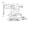
- FIG. 1 is a functional block diagram mainly showing the configuration of the regenerative brake torque command calculation unit according to the first embodiment.
- FIG. 2 is a functional block diagram mainly illustrating the configuration of the regenerative brake torque command calculation unit according to the second embodiment.
- FIG. 1 is a functional block diagram mainly showing the configuration of a regenerative brake torque command calculation unit according to the first embodiment, in which an upper stage shows a drive system of an AC electric vehicle, and a lower stage shows a regenerative torque control system.
- a regenerative brake torque command calculation unit 11 (hereinafter simply referred to as “calculation unit 11”) and a power running torque command / regenerative brake torque command calculation unit 12 (hereinafter simply referred to as “calculation unit 12”) are shown.
- the drive system of the AC electric vehicle has, as main components, the pantograph 1 to which AC power from the AC overhead line is input, the main transformer 2 to which AC power supplied from the panda graph 1 is input, and the AC of the main transformer 2 Converter 3 that converts AC voltage into DC voltage when voltage is applied, inverter 4 that converts DC voltage output from converter 3 into 3-phase AC, and DC voltage of converter 3 provided on the DC output side of inverter 4 is smoothed FC5, the main motor 6 driven by the AC voltage of the inverter 4, the auxiliary power supply device (hereinafter simply referred to as “SIV”) 7 connected to the intermediate DC circuit section 10, and the current for obtaining the load current provided on the input side of the SIV7 A sensor (hereinafter simply referred to as “CT”) 8 and a contactor 9 that is an open / close unit that separates the main transformer 2 and the converter 3 are configured.
- CT auxiliary power supply device
- One end of the primary side of the transformer 2 is connected to an AC overhead line via the pantograph 1, and the other end is connected to a rail that is a ground potential via a wheel (not shown). That is, the power transmitted from a substation (not shown) is configured to receive power via the AC overhead line, the pantograph 1, the wheels, and the rails.
- the control device for an AC electric vehicle performs power conversion as described above to drive the main motor 6 during powering of the electric vehicle, but drives the main motor 6 as a generator during braking, and the inverter 4 operates as an electric brake. It operates as a mode and applies a regenerative brake.
- the calculation unit 11 includes a first calculation processing unit 30, a second calculation processing unit 31, and an adder 26 as main components. Furthermore, the first arithmetic processing unit 30 includes a multiplier 22, a divider 23, and a gain adder 25, and the second arithmetic processing unit 31 includes a subtractor 21 and a PID arithmetic unit 24. Configured.
- the calculation unit 11 configured as described above calculates a regenerative torque command value TRQ1 for continuously operating the SIV 7 when the overhead power supply is lost.
- the computing unit 12 computes a normal power running torque command value or a regenerative torque command value.
- the switch 13 switches each output of the calculation unit 11 and the calculation unit 12.
- the operation of the control device for an AC electric vehicle when the overhead power supply is lost will be described.
- the power failure detector (not shown) detects the disappearance of the overhead power supply, the converter 3 is stopped, and the contactor 9 is opened.
- the inverter 4 continues to operate as the electric brake mode, the switch 13 is switched from the normal time to the power failure, and the regenerative torque command value TRQ1 for calculating the calculation unit 11 and controlling the inverter 4 is output.
- the multiplier 22 multiplies the SIV input current Isv input to the SIV7 obtained from CT8 and the DC voltage EcO detected from the FC5 to obtain the power consumed by the SIV7.
- the divider 23 outputs the output torque equivalent amount by dividing the power consumption of the SIV 7 by the rotor frequency FM (corresponding to the vehicle speed) of the main motor 7.
- the gain adder 25 adds a gain G1 to the output torque equivalent amount.
- the first regenerative torque command value TP1 for compensating the power consumption of SIV7 is output to the adder 26.
- the detection location of the DC voltage EcO may be the intermediate DC circuit unit 10, and is not limited to the FC5.
- the subtractor 21 obtains a deviation between a predetermined DC voltage command Ec * which is a DC voltage reference and the DC voltage EcO, and the PID calculator 24 is applied to the SIV 7 based on the deviation.
- a second regenerative torque command value TP2 is obtained in which the value of the DC voltage EcO is kept constant.
- the PID computing unit 24 is used as an example, it is not limited to this and may be a PD computing unit.
- the first regenerative torque command value TP1 and the second regenerative torque command value TP2 are added by the adder 26 to obtain a regenerative torque command value TRQ1 that is a torque command value for the continuous operation of SIV7.
- calculation unit 11 calculates regenerative torque command value TRQ1 corresponding to the power consumption of SIV7, Torque command value TRQ1 is output to inverter 4, and inverter 4 supplies regenerative power generated by electric motor 6 to intermediate DC circuit unit 10 in accordance with regenerative torque command value TRQ1. Therefore, SIV7 can continue the operation even when the overhead power supply is lost.
- the control apparatus for an AC electric vehicle is based on the SIV input current Isv, the DC voltage EcO, and the rotor frequency FM of the motor 6 when the overhead power supply disappears due to disconnection or the like.
- a first arithmetic processing unit 30 that calculates a regenerative torque command value TRQ1 that compensates for power consumption, and a regenerative torque command value TRQ2 that makes the DC voltage EcO constant based on the DC voltage EcO and the DC voltage command Ec *. Since the arithmetic unit 11 having two arithmetic processing units 31 is provided, the inverter 4 can be controlled without increasing the capacity of the FC 5 or adding special hardware (not shown) such as energy storage means.
- the regenerative power corresponding to the power consumption of SIV7 is supplied to the intermediate DC circuit unit 10, so that SIV7 is finely controlled. It is possible to continue operating Te.
- the regenerative power can be used effectively and the SIV 7 can be continuously operated, the amount of energy supplied from the overhead line can be reduced and the energy consumption can be reduced as compared with the prior art.
- Embodiment 2 In the control apparatus for an AC electric vehicle according to the second embodiment, either the first arithmetic processing unit 30 or the second arithmetic processing unit 31 is omitted from the arithmetic unit 11 according to the first embodiment. It is comprised so that the effect similar to Embodiment 1 can be acquired.
- the configuration and operation of the control device for an AC electric vehicle according to the present embodiment will be described below. Further, the same parts as those of the first embodiment are denoted by the same reference numerals, and detailed description thereof is omitted.
- FIG. 2 is a functional block diagram mainly showing the configuration of the regenerative brake torque command calculation unit according to the second embodiment.
- the first arithmetic processing unit 30 and the adder 26 shown in FIG. 1 are omitted.
- the SIV 7 consumes power
- the DC voltage EcO decreases when the converter 3 is not operating. Therefore, if the regenerative power amount of the inverter 4 is increased in accordance with the decrease in the DC voltage EcO, the first embodiment Equivalent function.
- the power failure detector (not shown) detects the disappearance of the overhead power supply, the converter 3 stops operating, and the contactor 9 is opened.
- the inverter 4 continues to operate in the electric brake mode, and the switch 13 is switched from a normal time to a power failure.
- the subtractor 21 obtains a deviation between the DC voltage command Ec * and the DC voltage EcO, and the PID computing unit 24 regenerates the torque command value TRQ2 based on the deviation. Get.
- the configuration of the control apparatus for an AC electric vehicle is not limited to the case where the first arithmetic processing unit 30 and the adder 26 are omitted, but is replaced with the second arithmetic processing unit 31.
- the first arithmetic processing unit 30 may be configured. That is, when the operation of the converter 3 is stopped when the overhead power supply is lost, power consumption by the SIV 7 is mainly performed. Therefore, even if the second arithmetic processing unit 31 is omitted, an equivalent function can be obtained by the first arithmetic processing unit 30. That is obvious.
- the control device for an AC electric vehicle has either the first arithmetic processing unit 30 or the second arithmetic processing unit 31 when the overhead power supply disappears due to a disconnection or the like. Therefore, the SIV 7 can be continuously operated as in the first embodiment, and the CT 8 can be omitted, so that the apparatus configuration is further simplified as compared with the first embodiment. Is possible. Moreover, when it comprises only the 1st arithmetic processing part 30, it can implement
- the control apparatus for an AC electric vehicle shown in the first and second embodiments shows an example of the contents of the present invention, and can be combined with another known technique. Of course, it is possible to change and configure such that a part is omitted without departing from the gist.
- the present invention can be applied to an AC electric vehicle control device, and is particularly useful as an invention for continuously operating an auxiliary power supply device that supplies power to a vehicle even when an overhead power supply is lost. .
Landscapes
- Engineering & Computer Science (AREA)
- Power Engineering (AREA)
- Transportation (AREA)
- Mechanical Engineering (AREA)
- Life Sciences & Earth Sciences (AREA)
- Sustainable Development (AREA)
- Sustainable Energy (AREA)
- Electric Propulsion And Braking For Vehicles (AREA)
Abstract
Description
2 主変圧器
3 コンバータ
4 インバータ
5 フィルタコンデンサ
6 主電動機
7 補助電源装置
8 電流センサ
9 接触器
10 中間直流回路部
11 回生ブレーキトルク指令演算部
12 力行トルク指令・回生ブレーキトルク指令演算部
13 スイッチ
21 減算器
22 乗算器
23 除算器
24 PID演算器
25 ゲイン付加器
26 加算器
30 第1の演算処理部
31 第2の演算処理部
Ec* 直流電圧指令(直流電圧基準)
EcO 直流電圧
FM ロータ周波数(電動機の周波数)
Isv SIV入力電流
TP1 第1の回生トルク指令値
TP2 第2の回生トルク指令値
TRQ1,TRQ2 回生トルク指令値
(交流電気車の制御装置の構成)
図1は、実施の形態1にかかる回生ブレーキトルク指令演算部の構成を主体として示す機能ブロック図であり、上段部には交流電気車の駆動系を示し、下段部には回生トルクの制御系を成す回生ブレーキトルク指令演算部11(以下単に「演算部11」と称する)、および力行トルク指令・回生ブレーキトルク指令演算部12(以下単に「演算部12」と称する)が示されている。
演算部11は、主たる構成として第1の演算処理部30、第2の演算処理部31、および加算器26を有して構成されている。さらに、第1の演算処理部30は、乗算器22、除算器23、およびゲイン付加器25を有して構成され、第2の演算処理部31は、減算器21およびPID演算器24を有して構成されている。このように構成された演算部11は、架線電源消失時にSIV7を継続動作させるための回生トルク指令値TRQ1を演算する。演算部12は、通常時の力行トルク指令値あるいは回生トルク指令値を演算する。スイッチ13は、演算部11および演算部12の各出力を切替える。
実施の形態2にかかる交流電気車の制御装置は、実施の形態1にかかる演算部11から、第1の演算処理部30または第2の演算処理部31の何れか一方が省略されても、実施の形態1と同様の効果を得ることができるように構成されている。以下、本実施の形態にかかる交流電気車の制御装置の構成および動作を説明する。また、第1の実施の形態と同様の部分については、同じ符号を付して詳細な説明は省略する。
Claims (4)
- 交流架線より変圧器を介して入力された交流電圧を直流電圧に変換するコンバータと、前記直流電圧を交流電圧に変換するインバータと、前記インバータにより駆動・制御される電動機とを備えた交流電気車の制御装置において、
前記電動機のトルク指令値を演算し前記インバータに出力するトルク指令演算部と、
前記交流電気車に搭載される負荷に電力を供給する補助電源装置と、
を備え、
前記コンバータに前記交流電圧が印加されない場合、前記トルク指令演算部は、前記補助電源装置の消費電力に応じた回生トルク指令値を演算し、
前記インバータは、前記回生トルク指令値に従って、前記電動機が発生した回生電力を前記補助電源装置に供給すること、
を特徴とする交流電気車の制御装置。 - 前記トルク指令演算部は、
前記補助電源装置の消費電力が補償される第1の回生トルク指令値と、前記補助電源装置に印加される直流電圧の値が一定に保たれる第2の回生トルク指令値との何れか1つを演算し、
前記インバータは、
前記第1の回生トルク指令値または前記第2の回生トルク指令値に従って、前記補助電源装置に前記回生電力を供給すること、
を特徴とする請求項1に記載の交流電気車の制御装置。 - 前記トルク指令演算部は、
前記補助電源装置の消費電力が補償される第1の回生トルク指令値と、前記補助電源装置に印加される直流電圧の値が一定に保たれる第2の回生トルク指令値とを演算し、
前記インバータは、
前記第1の回生トルク指令値および前記第2の回生トルク指令値に従って、前記補助電源装置に前記回生電力を供給すること
を特徴とする請求項1に記載の交流電気車の制御装置。 - 前記第1の回生トルク指令値は、
前記コンバータに交流電圧が印加されない場合、前記補助電源装置に印加される直流電圧、前記補助電源装置の入力電流、および前記電動機の周波数に基づいて生成され、
前記第2の回生トルク指令値は、
前記補助電源装置に印加される直流電圧および所定の直流電圧基準の差分に基づいて生成されること、
を特徴とする請求項2または3に記載の交流電気車の制御装置。
Priority Applications (12)
| Application Number | Priority Date | Filing Date | Title |
|---|---|---|---|
| MX2011009999A MX2011009999A (es) | 2009-03-25 | 2009-03-25 | Dispositivo de control de vehiculo electrico de ca. |
| KR1020117022277A KR101227708B1 (ko) | 2009-03-25 | 2009-03-25 | 교류 전기차의 제어장치 |
| RU2011142903/11A RU2479447C1 (ru) | 2009-03-25 | 2009-03-25 | Устройство управления для транспортного средства с электрическим двигателем переменного тока |
| CN200980158281.0A CN102361774B (zh) | 2009-03-25 | 2009-03-25 | 交流电动车辆的控制装置 |
| AU2009343024A AU2009343024B2 (en) | 2009-03-25 | 2009-03-25 | AC electric vehicle control device |
| US13/144,723 US8504230B2 (en) | 2009-03-25 | 2009-03-25 | Control apparatus for AC electric motor vehicle |
| PCT/JP2009/055954 WO2010109607A1 (ja) | 2009-03-25 | 2009-03-25 | 交流電気車の制御装置 |
| EP09842221.5A EP2412558B1 (en) | 2009-03-25 | 2009-03-25 | Ac electric vehicle control device |
| BRPI0924752A BRPI0924752A2 (pt) | 2009-03-25 | 2009-03-25 | aparelho de controle para um veículo a motor elétrico de corrente alternada |
| JP2009531689A JP4589448B2 (ja) | 2009-03-25 | 2009-03-25 | 交流電気車の制御装置 |
| CA2756408A CA2756408A1 (en) | 2009-03-25 | 2009-03-25 | Control apparatus for ac electric motor vehicle |
| ZA2011/06497A ZA201106497B (en) | 2009-03-25 | 2011-09-06 | Control apparatus for ac electric motor vehicle |
Applications Claiming Priority (1)
| Application Number | Priority Date | Filing Date | Title |
|---|---|---|---|
| PCT/JP2009/055954 WO2010109607A1 (ja) | 2009-03-25 | 2009-03-25 | 交流電気車の制御装置 |
Publications (1)
| Publication Number | Publication Date |
|---|---|
| WO2010109607A1 true WO2010109607A1 (ja) | 2010-09-30 |
Family
ID=42780316
Family Applications (1)
| Application Number | Title | Priority Date | Filing Date |
|---|---|---|---|
| PCT/JP2009/055954 Ceased WO2010109607A1 (ja) | 2009-03-25 | 2009-03-25 | 交流電気車の制御装置 |
Country Status (12)
| Country | Link |
|---|---|
| US (1) | US8504230B2 (ja) |
| EP (1) | EP2412558B1 (ja) |
| JP (1) | JP4589448B2 (ja) |
| KR (1) | KR101227708B1 (ja) |
| CN (1) | CN102361774B (ja) |
| AU (1) | AU2009343024B2 (ja) |
| BR (1) | BRPI0924752A2 (ja) |
| CA (1) | CA2756408A1 (ja) |
| MX (1) | MX2011009999A (ja) |
| RU (1) | RU2479447C1 (ja) |
| WO (1) | WO2010109607A1 (ja) |
| ZA (1) | ZA201106497B (ja) |
Cited By (3)
| Publication number | Priority date | Publication date | Assignee | Title |
|---|---|---|---|---|
| WO2014136220A1 (ja) | 2013-03-06 | 2014-09-12 | 三菱電機株式会社 | 電気車用主変換装置 |
| WO2017056588A1 (ja) * | 2015-10-01 | 2017-04-06 | 株式会社東芝 | 鉄道車両用電力変換装置 |
| WO2024009361A1 (ja) * | 2022-07-04 | 2024-01-11 | 三菱電機株式会社 | 鉄道車両用電力変換装置 |
Families Citing this family (9)
| Publication number | Priority date | Publication date | Assignee | Title |
|---|---|---|---|---|
| US9246432B2 (en) * | 2011-02-14 | 2016-01-26 | Beckman Coulter, Inc. | Regenerative braking safety system and method of use |
| US9333862B2 (en) | 2012-06-28 | 2016-05-10 | Mitsubishi Electric Corporation | Control device for AC electric vehicle |
| JP6139236B2 (ja) * | 2013-04-16 | 2017-05-31 | 株式会社東芝 | 電気機関車制御装置 |
| FR3024613B1 (fr) * | 2014-08-04 | 2017-10-06 | Alstom Transp Tech | Module d'alimentation electrique d'un bloc moteur, systeme de traction et vehicule electrique associe |
| CN104527444B (zh) * | 2014-12-16 | 2017-01-11 | 株洲南车时代电气股份有限公司 | 一种用于地铁车辆的供电系统及方法 |
| KR101605990B1 (ko) * | 2015-03-25 | 2016-03-23 | 영남대학교 산학협력단 | 인버터 벡터 구동 시스템 및 그것을 이용한 커패시터 용량 추정 방법 |
| CN108725211B (zh) * | 2018-06-25 | 2023-06-20 | 西南交通大学 | 一种磁浮列车三相供集电装置 |
| JP7278926B2 (ja) * | 2019-11-05 | 2023-05-22 | 株式会社日立製作所 | 電動機の制御装置、電動車両、電動機の制御方法 |
| RU208900U1 (ru) * | 2021-09-21 | 2022-01-21 | Общество с ограниченной ответственностью "Уральские локомотивы" | Устройство фильтрации скачков напряжения контактной сети постоянного тока |
Citations (4)
| Publication number | Priority date | Publication date | Assignee | Title |
|---|---|---|---|---|
| JPS5759401A (en) * | 1980-09-29 | 1982-04-09 | Japanese National Railways<Jnr> | Method of preventing instantaneous power interruption of service power source for passenger coach in insulated section of electric motor vehicle |
| JPS60200790A (ja) * | 1984-03-26 | 1985-10-11 | Toshiba Corp | 交流電動機駆動装置 |
| JPH02219401A (ja) * | 1989-02-20 | 1990-09-03 | Hitachi Ltd | 電気車の制御装置 |
| JP2003199354A (ja) | 2001-12-25 | 2003-07-11 | Toshiba Corp | 電力変換装置 |
Family Cites Families (16)
| Publication number | Priority date | Publication date | Assignee | Title |
|---|---|---|---|---|
| BR7806854A (pt) * | 1977-10-18 | 1979-05-15 | Tokyo Shibaura Electric Co | Processo para controlar a velocidade de um motor a corrente alternada |
| SE450318B (sv) * | 1980-09-25 | 1987-06-15 | Asea Ab | Sjelvkommuterad stromriktare for overforing av effekt mellan en motor och ett net for drivning och bromsning av motorn |
| US4491768A (en) * | 1981-11-04 | 1985-01-01 | Eaton Corporation | Pulse width modulation inverter with battery charger |
| DE3304377C2 (de) | 1983-02-09 | 1985-12-19 | Fried. Krupp Gmbh, 4300 Essen | Einrichtung zur Energieversorgung von Nutzverbrauchern in einem Schienenfahrzeug |
| US4843296A (en) * | 1986-06-23 | 1989-06-27 | Kabushiki Kaisha Toshiba | AC motor drive apparatus |
| JPH0274192A (ja) * | 1988-09-08 | 1990-03-14 | Toshiba Corp | 電力変換装置 |
| JPH07123501A (ja) | 1993-10-28 | 1995-05-12 | Toshiba Corp | 電気車制御装置 |
| JPH07212909A (ja) * | 1994-01-12 | 1995-08-11 | Toshiba Corp | 電気車制御装置 |
| JPH0865811A (ja) * | 1994-08-25 | 1996-03-08 | Toshiba Corp | 電気車制御装置 |
| US6307759B1 (en) | 1997-10-31 | 2001-10-23 | Hitachi, Ltd. | Control device for electric power translating device |
| US20060005739A1 (en) * | 2001-03-27 | 2006-01-12 | Kumar Ajith K | Railroad system comprising railroad vehicle with energy regeneration |
| JP4013905B2 (ja) | 2003-05-21 | 2007-11-28 | トヨタ自動車株式会社 | 動力出力装置およびその制御方法並びに自動車 |
| RU39306U1 (ru) | 2004-03-18 | 2004-07-27 | Брянский государственный технический университет | Устройство управления подвижным составом с асинхронными тяговыми двигателями, обеспечивающее предупреждение боксования и юза |
| JP4962184B2 (ja) | 2007-07-18 | 2012-06-27 | トヨタ自動車株式会社 | 車両の電源装置 |
| US8258735B2 (en) * | 2008-12-15 | 2012-09-04 | Mitsubishi Electric Corporation | Power converting apparatus for motor driving |
| US8476859B2 (en) * | 2010-09-30 | 2013-07-02 | Rockwell Automation Technologies, Inc. | DC power for SGCT devices using a high frequency current loop with multiple current transformers |
-
2009
- 2009-03-25 WO PCT/JP2009/055954 patent/WO2010109607A1/ja not_active Ceased
- 2009-03-25 EP EP09842221.5A patent/EP2412558B1/en active Active
- 2009-03-25 BR BRPI0924752A patent/BRPI0924752A2/pt not_active Application Discontinuation
- 2009-03-25 AU AU2009343024A patent/AU2009343024B2/en not_active Ceased
- 2009-03-25 KR KR1020117022277A patent/KR101227708B1/ko not_active Expired - Fee Related
- 2009-03-25 CN CN200980158281.0A patent/CN102361774B/zh active Active
- 2009-03-25 RU RU2011142903/11A patent/RU2479447C1/ru not_active IP Right Cessation
- 2009-03-25 US US13/144,723 patent/US8504230B2/en active Active
- 2009-03-25 CA CA2756408A patent/CA2756408A1/en not_active Abandoned
- 2009-03-25 MX MX2011009999A patent/MX2011009999A/es active IP Right Grant
- 2009-03-25 JP JP2009531689A patent/JP4589448B2/ja not_active Expired - Fee Related
-
2011
- 2011-09-06 ZA ZA2011/06497A patent/ZA201106497B/en unknown
Patent Citations (4)
| Publication number | Priority date | Publication date | Assignee | Title |
|---|---|---|---|---|
| JPS5759401A (en) * | 1980-09-29 | 1982-04-09 | Japanese National Railways<Jnr> | Method of preventing instantaneous power interruption of service power source for passenger coach in insulated section of electric motor vehicle |
| JPS60200790A (ja) * | 1984-03-26 | 1985-10-11 | Toshiba Corp | 交流電動機駆動装置 |
| JPH02219401A (ja) * | 1989-02-20 | 1990-09-03 | Hitachi Ltd | 電気車の制御装置 |
| JP2003199354A (ja) | 2001-12-25 | 2003-07-11 | Toshiba Corp | 電力変換装置 |
Cited By (8)
| Publication number | Priority date | Publication date | Assignee | Title |
|---|---|---|---|---|
| WO2014136220A1 (ja) | 2013-03-06 | 2014-09-12 | 三菱電機株式会社 | 電気車用主変換装置 |
| JP5968518B2 (ja) * | 2013-03-06 | 2016-08-10 | 三菱電機株式会社 | 電気車用主変換装置 |
| US9764647B2 (en) | 2013-03-06 | 2017-09-19 | Mitsubishi Electric Corporation | Main conversion device for electric vehicle |
| WO2017056588A1 (ja) * | 2015-10-01 | 2017-04-06 | 株式会社東芝 | 鉄道車両用電力変換装置 |
| JPWO2017056588A1 (ja) * | 2015-10-01 | 2018-06-14 | 株式会社東芝 | 鉄道車両用電力変換装置 |
| WO2024009361A1 (ja) * | 2022-07-04 | 2024-01-11 | 三菱電機株式会社 | 鉄道車両用電力変換装置 |
| JPWO2024009361A1 (ja) * | 2022-07-04 | 2024-01-11 | ||
| JP7584712B2 (ja) | 2022-07-04 | 2024-11-15 | 三菱電機株式会社 | 鉄道車両用電力変換装置 |
Also Published As
| Publication number | Publication date |
|---|---|
| CN102361774B (zh) | 2014-02-19 |
| JP4589448B2 (ja) | 2010-12-01 |
| AU2009343024A1 (en) | 2011-10-06 |
| KR101227708B1 (ko) | 2013-01-29 |
| AU2009343024B2 (en) | 2013-08-29 |
| EP2412558A1 (en) | 2012-02-01 |
| KR20110119824A (ko) | 2011-11-02 |
| EP2412558A4 (en) | 2013-05-15 |
| MX2011009999A (es) | 2011-10-11 |
| CN102361774A (zh) | 2012-02-22 |
| EP2412558B1 (en) | 2017-09-06 |
| RU2479447C1 (ru) | 2013-04-20 |
| US20110276214A1 (en) | 2011-11-10 |
| CA2756408A1 (en) | 2010-09-30 |
| ZA201106497B (en) | 2012-11-28 |
| US8504230B2 (en) | 2013-08-06 |
| JPWO2010109607A1 (ja) | 2012-09-20 |
| BRPI0924752A2 (pt) | 2016-01-26 |
Similar Documents
| Publication | Publication Date | Title |
|---|---|---|
| JP4589448B2 (ja) | 交流電気車の制御装置 | |
| JP5343599B2 (ja) | モータ制御装置及び電動パワーステアリング装置 | |
| JP2656684B2 (ja) | エレベータの停電時運転装置 | |
| TWI770019B (zh) | 電車用電力轉換控制裝置 | |
| JP5968518B2 (ja) | 電気車用主変換装置 | |
| JP6203036B2 (ja) | 電気車制御装置 | |
| JP4657215B2 (ja) | 交流回転機の制御装置および交流回転機の制御方法 | |
| WO2019130563A1 (ja) | 電気車制御装置 | |
| JP6069151B2 (ja) | 電力変換装置の制御回路 | |
| JP6257931B2 (ja) | 電気駆動車両、電気駆動車両の制御装置及び電気駆動車両の制御方法 | |
| JP2005143274A (ja) | 電動車両の駆動制御装置及び駆動制御方法 | |
| JP2011250616A (ja) | モータ駆動装置及びモータ駆動車両 | |
| JP4945493B2 (ja) | 電動機制御方法及び電動機制御装置 | |
| JP4964215B2 (ja) | 交流電気車の制御装置 | |
| JP5523639B2 (ja) | 電気車制御装置 | |
| JP2005218186A (ja) | 交流電気車の制御装置 | |
| JP3747858B2 (ja) | 車両用インバータの制御方法およびインバータ制御器 | |
| JP2011010506A (ja) | 電気車の電力変換装置 | |
| WO2016194140A1 (ja) | エレベータの制御装置およびエレベータの制御方法 | |
| HK1117950B (en) | Ac rotating machine control apparatus and ac rotating machine control method |
Legal Events
| Date | Code | Title | Description |
|---|---|---|---|
| WWE | Wipo information: entry into national phase |
Ref document number: 200980158281.0 Country of ref document: CN |
|
| WWE | Wipo information: entry into national phase |
Ref document number: 2009531689 Country of ref document: JP |
|
| 121 | Ep: the epo has been informed by wipo that ep was designated in this application |
Ref document number: 09842221 Country of ref document: EP Kind code of ref document: A1 |
|
| WWE | Wipo information: entry into national phase |
Ref document number: 13144723 Country of ref document: US |
|
| REEP | Request for entry into the european phase |
Ref document number: 2009842221 Country of ref document: EP |
|
| WWE | Wipo information: entry into national phase |
Ref document number: 2009842221 Country of ref document: EP |
|
| WWE | Wipo information: entry into national phase |
Ref document number: 2009343024 Country of ref document: AU |
|
| WWE | Wipo information: entry into national phase |
Ref document number: 2756408 Country of ref document: CA |
|
| ENP | Entry into the national phase |
Ref document number: 20117022277 Country of ref document: KR Kind code of ref document: A |
|
| WWE | Wipo information: entry into national phase |
Ref document number: 6885/CHENP/2011 Country of ref document: IN Ref document number: MX/A/2011/009999 Country of ref document: MX |
|
| NENP | Non-entry into the national phase |
Ref country code: DE |
|
| ENP | Entry into the national phase |
Ref document number: 2009343024 Country of ref document: AU Date of ref document: 20090325 Kind code of ref document: A |
|
| ENP | Entry into the national phase |
Ref document number: 2011142903 Country of ref document: RU Kind code of ref document: A |
|
| REG | Reference to national code |
Ref country code: BR Ref legal event code: B01A Ref document number: PI0924752 Country of ref document: BR |
|
| ENP | Entry into the national phase |
Ref document number: PI0924752 Country of ref document: BR Kind code of ref document: A2 Effective date: 20110920 |