WO2010103649A1 - 複合抵抗変化素子及びその製造方法 - Google Patents
複合抵抗変化素子及びその製造方法 Download PDFInfo
- Publication number
- WO2010103649A1 WO2010103649A1 PCT/JP2009/054812 JP2009054812W WO2010103649A1 WO 2010103649 A1 WO2010103649 A1 WO 2010103649A1 JP 2009054812 W JP2009054812 W JP 2009054812W WO 2010103649 A1 WO2010103649 A1 WO 2010103649A1
- Authority
- WO
- WIPO (PCT)
- Prior art keywords
- resistance
- change element
- film
- variable resistance
- state
- Prior art date
Links
Images


Classifications
-
- G—PHYSICS
- G11—INFORMATION STORAGE
- G11C—STATIC STORES
- G11C11/00—Digital stores characterised by the use of particular electric or magnetic storage elements; Storage elements therefor
- G11C11/56—Digital stores characterised by the use of particular electric or magnetic storage elements; Storage elements therefor using storage elements with more than two stable states represented by steps, e.g. of voltage, current, phase, frequency
- G11C11/5685—Digital stores characterised by the use of particular electric or magnetic storage elements; Storage elements therefor using storage elements with more than two stable states represented by steps, e.g. of voltage, current, phase, frequency using storage elements comprising metal oxide memory material, e.g. perovskites
-
- G—PHYSICS
- G11—INFORMATION STORAGE
- G11C—STATIC STORES
- G11C11/00—Digital stores characterised by the use of particular electric or magnetic storage elements; Storage elements therefor
- G11C11/02—Digital stores characterised by the use of particular electric or magnetic storage elements; Storage elements therefor using magnetic elements
- G11C11/16—Digital stores characterised by the use of particular electric or magnetic storage elements; Storage elements therefor using magnetic elements using elements in which the storage effect is based on magnetic spin effect
- G11C11/161—Digital stores characterised by the use of particular electric or magnetic storage elements; Storage elements therefor using magnetic elements using elements in which the storage effect is based on magnetic spin effect details concerning the memory cell structure, e.g. the layers of the ferromagnetic memory cell
-
- G—PHYSICS
- G11—INFORMATION STORAGE
- G11C—STATIC STORES
- G11C11/00—Digital stores characterised by the use of particular electric or magnetic storage elements; Storage elements therefor
- G11C11/56—Digital stores characterised by the use of particular electric or magnetic storage elements; Storage elements therefor using storage elements with more than two stable states represented by steps, e.g. of voltage, current, phase, frequency
- G11C11/5678—Digital stores characterised by the use of particular electric or magnetic storage elements; Storage elements therefor using storage elements with more than two stable states represented by steps, e.g. of voltage, current, phase, frequency using amorphous/crystalline phase transition storage elements
-
- G—PHYSICS
- G11—INFORMATION STORAGE
- G11C—STATIC STORES
- G11C13/00—Digital stores characterised by the use of storage elements not covered by groups G11C11/00, G11C23/00, or G11C25/00
- G11C13/0002—Digital stores characterised by the use of storage elements not covered by groups G11C11/00, G11C23/00, or G11C25/00 using resistive RAM [RRAM] elements
- G11C13/0004—Digital stores characterised by the use of storage elements not covered by groups G11C11/00, G11C23/00, or G11C25/00 using resistive RAM [RRAM] elements comprising amorphous/crystalline phase transition cells
-
- G—PHYSICS
- G11—INFORMATION STORAGE
- G11C—STATIC STORES
- G11C13/00—Digital stores characterised by the use of storage elements not covered by groups G11C11/00, G11C23/00, or G11C25/00
- G11C13/0002—Digital stores characterised by the use of storage elements not covered by groups G11C11/00, G11C23/00, or G11C25/00 using resistive RAM [RRAM] elements
- G11C13/0007—Digital stores characterised by the use of storage elements not covered by groups G11C11/00, G11C23/00, or G11C25/00 using resistive RAM [RRAM] elements comprising metal oxide memory material, e.g. perovskites
-
- H—ELECTRICITY
- H10—SEMICONDUCTOR DEVICES; ELECTRIC SOLID-STATE DEVICES NOT OTHERWISE PROVIDED FOR
- H10B—ELECTRONIC MEMORY DEVICES
- H10B61/00—Magnetic memory devices, e.g. magnetoresistive RAM [MRAM] devices
-
- H—ELECTRICITY
- H10—SEMICONDUCTOR DEVICES; ELECTRIC SOLID-STATE DEVICES NOT OTHERWISE PROVIDED FOR
- H10B—ELECTRONIC MEMORY DEVICES
- H10B61/00—Magnetic memory devices, e.g. magnetoresistive RAM [MRAM] devices
- H10B61/20—Magnetic memory devices, e.g. magnetoresistive RAM [MRAM] devices comprising components having three or more electrodes, e.g. transistors
- H10B61/22—Magnetic memory devices, e.g. magnetoresistive RAM [MRAM] devices comprising components having three or more electrodes, e.g. transistors of the field-effect transistor [FET] type
-
- H—ELECTRICITY
- H10—SEMICONDUCTOR DEVICES; ELECTRIC SOLID-STATE DEVICES NOT OTHERWISE PROVIDED FOR
- H10B—ELECTRONIC MEMORY DEVICES
- H10B63/00—Resistance change memory devices, e.g. resistive RAM [ReRAM] devices
- H10B63/30—Resistance change memory devices, e.g. resistive RAM [ReRAM] devices comprising selection components having three or more electrodes, e.g. transistors
-
- G—PHYSICS
- G11—INFORMATION STORAGE
- G11C—STATIC STORES
- G11C11/00—Digital stores characterised by the use of particular electric or magnetic storage elements; Storage elements therefor
- G11C11/56—Digital stores characterised by the use of particular electric or magnetic storage elements; Storage elements therefor using storage elements with more than two stable states represented by steps, e.g. of voltage, current, phase, frequency
- G11C11/5607—Digital stores characterised by the use of particular electric or magnetic storage elements; Storage elements therefor using storage elements with more than two stable states represented by steps, e.g. of voltage, current, phase, frequency using magnetic storage elements
-
- G—PHYSICS
- G11—INFORMATION STORAGE
- G11C—STATIC STORES
- G11C2213/00—Indexing scheme relating to G11C13/00 for features not covered by this group
- G11C2213/10—Resistive cells; Technology aspects
- G11C2213/15—Current-voltage curve
-
- G—PHYSICS
- G11—INFORMATION STORAGE
- G11C—STATIC STORES
- G11C2213/00—Indexing scheme relating to G11C13/00 for features not covered by this group
- G11C2213/30—Resistive cell, memory material aspects
- G11C2213/34—Material includes an oxide or a nitride
-
- G—PHYSICS
- G11—INFORMATION STORAGE
- G11C—STATIC STORES
- G11C2213/00—Indexing scheme relating to G11C13/00 for features not covered by this group
- G11C2213/70—Resistive array aspects
- G11C2213/79—Array wherein the access device being a transistor
-
- H—ELECTRICITY
- H10—SEMICONDUCTOR DEVICES; ELECTRIC SOLID-STATE DEVICES NOT OTHERWISE PROVIDED FOR
- H10N—ELECTRIC SOLID-STATE DEVICES NOT OTHERWISE PROVIDED FOR
- H10N70/00—Solid-state devices without a potential-jump barrier or surface barrier, and specially adapted for rectifying, amplifying, oscillating or switching
- H10N70/801—Constructional details of multistable switching devices
- H10N70/821—Device geometry
- H10N70/826—Device geometry adapted for essentially vertical current flow, e.g. sandwich or pillar type devices
-
- H—ELECTRICITY
- H10—SEMICONDUCTOR DEVICES; ELECTRIC SOLID-STATE DEVICES NOT OTHERWISE PROVIDED FOR
- H10N—ELECTRIC SOLID-STATE DEVICES NOT OTHERWISE PROVIDED FOR
- H10N70/00—Solid-state devices without a potential-jump barrier or surface barrier, and specially adapted for rectifying, amplifying, oscillating or switching
- H10N70/801—Constructional details of multistable switching devices
- H10N70/881—Switching materials
- H10N70/882—Compounds of sulfur, selenium or tellurium, e.g. chalcogenides
- H10N70/8828—Tellurides, e.g. GeSbTe
-
- H—ELECTRICITY
- H10—SEMICONDUCTOR DEVICES; ELECTRIC SOLID-STATE DEVICES NOT OTHERWISE PROVIDED FOR
- H10N—ELECTRIC SOLID-STATE DEVICES NOT OTHERWISE PROVIDED FOR
- H10N70/00—Solid-state devices without a potential-jump barrier or surface barrier, and specially adapted for rectifying, amplifying, oscillating or switching
- H10N70/801—Constructional details of multistable switching devices
- H10N70/881—Switching materials
- H10N70/883—Oxides or nitrides
- H10N70/8833—Binary metal oxides, e.g. TaOx
Definitions
- the present invention relates to a composite variable resistance element and a manufacturing method thereof.
- MRAM Magnetic Random Access Memory
- ReRAM Resistive Random Access Memory
- PCRAM Phase Research such as Change Random Access Memory
- the resistance change element is configured so that two states of a high resistance state and a low resistance state occur in the electric resistance, and binary (“0” and “1”) can be stored.
- the MRAM stores information by using a change in magnetoresistance associated with a change in current magnitude.
- the ReRAM stores information by utilizing a change in resistance that accompanies changes in the magnitude of current and voltage.
- PCRAM stores information by utilizing a change in resistance accompanying a change in crystal phase.
- TMR Tunnelnel A magnetoresistive change element such as a Magneto-Resistance element is provided in each memory cell.
- the TMR element is provided with a ferromagnetic layer (fixed layer) having a fixed magnetization direction, a ferromagnetic layer (free layer) having a variable magnetization direction, and an insulating layer (barrier layer) provided therebetween. It has been.
- Such a TMR element is in a low resistance state when the magnetization direction of the free layer coincides with the magnetization direction of the fixed layer (parallel), and the magnetization direction of the free layer is opposite to the magnetization direction of the fixed layer. In this case (antiparallel), a high resistance state is obtained.
- a magnetic field generated by the current can be freely passed by passing a current through a specific wiring (sometimes called a write word line) provided in each memory cell.
- a specific wiring sometimes called a write word line
- a structure employing this method is sometimes called a write wiring type.
- a current is directly passed to the TMR element and a spin torque effect generated along with this is used.
- a structure employing this method is sometimes called a spin injection type. Note that the current required to change the magnetization direction of the free layer is proportional to the size of the element.
- the spin injection type does not require a wiring (write word line) for controlling the direction of magnetization. For this reason, it is suitable for high density. Further, as described above, since the current necessary for changing the magnetization direction of the free layer is proportional to the size of the element, the current necessary for rewriting information can be reduced as the size is reduced. Therefore, in recent years, spin injection type MRAM has attracted attention.
- each memory cell is provided with a resistance change element whose electric resistance changes with changes in current and voltage.
- the resistance change element is provided with two electrodes and a resistance change film provided therebetween.
- the resistance of the resistance change film changes according to the magnitude of the current, and an oxide containing a transition metal such as nickel oxide is used as the material.
- PCRAM is sometimes called phase change memory.
- each memory cell is provided with a resistance change element whose electric resistance changes with a change in crystal phase.
- the resistance change element is provided with a phase change layer made of a material that becomes an amorphous state or a crystalline state in accordance with a temperature change or the like.
- Such a phase change layer is in a high resistance state when in an amorphous state and is in a low resistance state when in a crystalline state.
- As a method for changing the phase there is a method in which an electric current is passed and Joule heat generated along with this is used.
- phase change layer When the phase change layer is in an amorphous state (high resistance state), a current is applied to the phase change layer, and when the current increases to some extent, the phase change layer is heated by Joule heat to enter a crystalline state (low resistance state). Change. When the voltage is lowered as it is, the crystalline state is maintained. On the other hand, when the phase change layer is in a crystalline state (low resistance state) and a current of a predetermined value or more is passed through it, the crystal melts and the phase change layer changes to an amorphous state (high resistance state). Furthermore, the voltage increases and the current decreases with the change to the high resistance state. When the voltage is lowered as it is, the amorphous state is maintained.
- phase states of the two phase change layers there are four types of combinations of the phase states of the two phase change layers, it is not possible to change between these four types of states by a single process. For example, even if it is possible to change from one state to another by only a single process, the reverse change cannot be performed by a single process, and it passes through another state on the way. There are things you have to do. This complicates the control.
- An object of the present invention is to provide a composite resistance change element capable of obtaining four types of resistance states by simple control and a method for manufacturing the same.
- a first variable resistance element whose resistance value changes in accordance with the direction of internal magnetization, and a second variable resistance element connected in series to the first variable resistance element And are provided.
- the resistance value of the second variable resistance element is equal to or greater than at least one of the voltage and the current regardless of whether the voltage applied to the second variable resistance element or the current flowing through the second variable resistance element is positive or negative.
- the resistance value changes according to the size.
- a first variable resistance element whose resistance value changes according to the direction of internal magnetization is formed, and a second variable resistance element connected in series to the first variable resistance element.
- the variable resistance element is formed.
- the resistance value of the second variable resistance element is equal to or greater than at least one of the voltage and the current regardless of whether the voltage applied to the second variable resistance element or the current flowing through the second variable resistance element is positive or negative.
- the resistance value changes according to the size.
- FIG. 1 is a circuit diagram showing a part of the semiconductor memory device according to the first embodiment.
- FIG. 2 is a diagram showing a layout of a portion indicated by a two-dot chain line in FIG.
- FIG. 3A is a cross-sectional view taken along line II in FIG. 2 in the first embodiment.
- FIG. 3B is a cross-sectional view taken along the line II-II in FIG. 2 in the first embodiment.
- FIG. 4 is a cross-sectional view showing the structure of the magnetoresistance change element 1 and the resistance change element 2 in the first embodiment.
- FIG. 5A is a diagram showing the characteristics of the magnetoresistive change element 1.
- FIG. 5B is a diagram illustrating characteristics of the variable resistance element 2.
- FIG. 5A is a diagram showing the characteristics of the magnetoresistive change element 1.
- FIG. 5B is a diagram illustrating characteristics of the variable resistance element 2.
- FIG. 6A is a diagram illustrating characteristics in the case where both the magnetoresistance change element 1 and the resistance change element 2 are in the low resistance state (L / L) in the initial state.
- FIG. 6B is a diagram showing characteristics in the initial state when the magnetoresistance change element 1 is in a high resistance state and the resistance change element 2 is in a low resistance state (H / L).
- FIG. 6C is a diagram illustrating characteristics in the initial state when the magnetoresistance change element 1 is in the low resistance state and the resistance change element 2 is in the high resistance state (L / H).
- FIG. 6D is a diagram illustrating characteristics when both the magnetoresistance change element 1 and the resistance change element 2 are in a low resistance state (H / H) in an initial state.
- FIG. 7A is a cross-sectional view showing the method of manufacturing the semiconductor memory device according to the first embodiment.
- FIG. 7B is a cross-sectional view showing a method for manufacturing the semiconductor memory device, following FIG. 7A.
- FIG. 7C is a cross-sectional view showing a method for manufacturing the semiconductor memory device, following FIG. 7B.
- FIG. 7D is a cross-sectional view showing a method for manufacturing the semiconductor memory device, following FIG. 7C.
- FIG. 8A is a cross-sectional view showing a method of forming the magnetoresistance change element 1 and the resistance change element 2 in the first embodiment.
- FIG. 8B is a cross-sectional view illustrating a method of forming the magnetoresistance change element 1 and the resistance change element 2 following FIG. 8A.
- FIG. 8A is a cross-sectional view showing a method of forming the magnetoresistance change element 1 and the resistance change element 2 following FIG. 8A.
- FIG. 8C is a cross-sectional view illustrating a method of forming the magnetoresistance change element 1 and the resistance change element 2 subsequent to FIG. 8B.
- FIG. 8D is a cross-sectional view illustrating a method of forming the magnetoresistance change element 1 and the resistance change element 2 following FIG. 8C.
- FIG. 8E is a cross-sectional view illustrating a method of forming the magnetoresistance change element 1 and the resistance change element 2 following FIG. 8D.
- FIG. 9 is a cross-sectional view showing the structure of the magnetoresistance change element 1 and the resistance change element 2 in the second embodiment.
- FIG. 10A is a cross-sectional view illustrating a method of forming the magnetoresistance change element 1 and the resistance change element 2 in the second embodiment.
- FIG. 10B is a cross-sectional view illustrating a method of forming the magnetoresistance change element 1 and the resistance change element 2 following FIG. 10A.
- FIG. 10C is a cross-sectional view illustrating a method of forming the magnetoresistance change element 1 and the resistance change element 2 subsequent to FIG. 10B.
- FIG. 10D is a cross-sectional view illustrating a method of forming the magnetoresistance change element 1 and the resistance change element 2 following FIG. 10C.
- FIG. 11 is a cross-sectional view showing the structures of the magnetoresistance change element 1 and the resistance change element 2 in the third embodiment.
- FIG. 10B is a cross-sectional view illustrating a method of forming the magnetoresistance change element 1 and the resistance change element 2 following FIG. 10A.
- FIG. 10C is a cross-sectional view illustrating a method of forming the magnetoresistance change element 1 and the resistance change element 2 subsequent to FIG. 10B.
- FIG. 10D is
- FIG. 12A is a cross-sectional view illustrating a method of forming the magnetoresistance change element 1 and the resistance change element 2 in the third embodiment.
- FIG. 12B is a cross-sectional view illustrating a method of forming the magnetoresistance change element 1 and the resistance change element 2 subsequent to FIG. 12A.
- FIG. 12C is a cross-sectional view illustrating a method of forming the magnetoresistance change element 1 and the resistance change element 2 subsequent to FIG. 12B.
- FIG. 12D is a cross-sectional view illustrating a method of forming the magnetoresistance change element 1 and the resistance change element 2 subsequent to FIG. 12C.
- FIG. 12A is a cross-sectional view illustrating a method of forming the magnetoresistance change element 1 and the resistance change element 2 in the third embodiment.
- FIG. 12B is a cross-sectional view illustrating a method of forming the magnetoresistance change element 1 and the resistance change element 2 subsequent to FIG. 12A.
- FIG. 13 is a cross-sectional view showing the structure of the magnetoresistance change element 1 and the resistance change element 2 in the fourth embodiment.
- FIG. 14A is a cross-sectional view illustrating a method of forming the magnetoresistance change element 1 and the resistance change element 2 in the fourth embodiment.
- 14B is a cross-sectional view illustrating a method of forming the magnetoresistance change element 1 and the resistance change element 2 following FIG. 14A.
- FIG. 14C is a cross-sectional view illustrating a method of forming the magnetoresistance change element 1 and the resistance change element 2 subsequent to FIG. 14B.
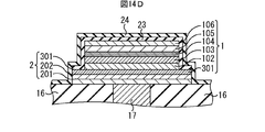
- 14D is a cross-sectional view illustrating a method of forming the magnetoresistance change element 1 and the resistance change element 2 following FIG. 14C.
- FIG. 14A is a cross-sectional view illustrating a method of forming the magnetoresistance change element 1 and the resistance change element 2 in the fourth embodiment.
- 14B is a cross-sectional view illustrating
- FIG. 15A is a sectional view taken along line II in FIG. 2 in the fifth embodiment.
- FIG. 15B is a sectional view taken along line II-II in FIG. 2 in the fifth embodiment.
- FIG. 16A is a cross-sectional view illustrating the method of manufacturing the semiconductor memory device according to the fifth embodiment.
- FIG. 16B is a cross-sectional view showing a method for manufacturing the semiconductor memory device, following FIG. 16A.
- FIG. 17A is a cross-sectional view illustrating a method of forming the magnetoresistance change element 1 and the resistance change element 2 in the fifth embodiment.
- FIG. 17B is a cross-sectional view illustrating a method of forming the magnetoresistance change element 1 and the resistance change element 2 following FIG. 17A.
- FIG. 17A is a cross-sectional view taken along line II in FIG. 2 in the fifth embodiment.
- FIG. 15B is a sectional view taken along line II-II in FIG. 2 in the fifth embodiment.
- FIG. 17C is a cross-sectional view illustrating a method of forming the magnetoresistance change element 1 and the resistance change element 2 following FIG. 17B.
- FIG. 17D is a cross-sectional view illustrating a method of forming the magnetoresistance change element 1 and the resistance change element 2 following FIG. 17C.
- FIG. 17E is a cross-sectional view illustrating a method of forming the magnetoresistance change element 1 and the resistance change element 2 subsequent to FIG. 17D.
- FIG. 17F is a cross-sectional view illustrating a method of forming the magnetoresistance change element 1 and the resistance change element 2 subsequent to FIG. 17E.
- FIG. 17C is a cross-sectional view illustrating a method of forming the magnetoresistance change element 1 and the resistance change element 2 following FIG. 17B.
- FIG. 17D is a cross-sectional view illustrating a method of forming the magnetoresistance change element 1 and the resistance change element 2 following FIG. 17C.
- FIG. 17G is a cross-sectional view illustrating a method of forming the magnetoresistance change element 1 and the resistance change element 2 subsequent to FIG. 17F.
- FIG. 17H is a cross-sectional view illustrating a method of forming the magnetoresistance change element 1 and the resistance change element 2 following FIG. 17G.
- FIG. 18A is a diagram illustrating characteristics in a case where both of the magnetoresistance change elements are in a low resistance state (L / L) in an initial state.
- FIG. 18B is a diagram illustrating characteristics in the initial state when the magnetoresistance change element on the bit line BL side is in a high resistance state and the magnetoresistance change element on the transistor Tr side is in a low resistance state (H / L).
- FIG. 18A is a diagram illustrating characteristics in a case where both of the magnetoresistance change elements are in a low resistance state (L / L) in an initial state.
- FIG. 18B is a diagram illustrating characteristics in the initial
- FIG. 18C is a diagram illustrating characteristics in the initial state when the magnetoresistance change element on the bit line BL side is in the low resistance state and the magnetoresistance change element on the transistor Tr side is in the high resistance state (L / H).
- FIG. 18D is a diagram showing characteristics when both magnetoresistive elements are in a low resistance state (H / H) in an initial state.
- FIG. 19A is a diagram illustrating characteristics in a case where both of the variable resistance elements are in a low resistance state (L / L) in an initial state.
- FIG. 19B is a diagram showing characteristics in the initial state when the resistance change element on the bit line BL side is in a high resistance state and the resistance change element on the transistor Tr side is in a low resistance state (H / L).
- FIG. 19C is a diagram showing characteristics in the initial state when the resistance change element on the bit line BL side is in the low resistance state and the resistance change element on the transistor Tr side is in the high resistance state (L / H).
- FIG. 19D is a diagram illustrating characteristics in the initial state when both of the variable resistance elements are in a low resistance state (H / H).
- FIG. 1 is a circuit diagram showing a part of the semiconductor memory device according to the first embodiment
- FIG. 2 is a diagram showing a layout of a part indicated by a two-dot chain line in FIG.
- a plurality of memory cells are arranged in an array vertically and horizontally.
- FIG. 1 shows four of them, and FIG. 2 shows two of them.
- Each memory cell is provided with one word line WL, one bit line BL, and one signal line SL.
- the word line WL is shared by a plurality of memory cells arranged in the vertical direction
- the bit line BL and the signal line SL are shared by a plurality of memory cells arranged in the horizontal direction.
- Each memory cell is provided with one magnetoresistance change element 1, one resistance change element 2, and a transistor Tr.
- the word line WL also serves as the gate electrode of the transistor Tr.
- One of the source / drain of the transistor Tr is connected to the signal line SL, and the other is connected to one electrode of the resistance change element 2.
- the other electrode of the resistance change element 2 is connected to one electrode of the magnetoresistance change element 1.
- the other electrode of the magnetoresistance change element 1 is connected to the bit line BL.
- the magnetoresistance change element 1 and the resistance change element 2 constitute a composite change element.
- FIG. 3A is a cross-sectional view taken along line II in FIG. 2 in the first embodiment
- FIG. 3B is a cross-sectional view taken along line II-II in FIG. 2 in the first embodiment. is there.
- one memory cell will be described.
- an element isolation insulating film 12 that defines an element region on the surface of a semiconductor substrate 11 such as a silicon substrate is formed by an STI (shallow trench isolation) method or the like. ing.
- a transistor Tr is formed in the element region.
- An interlayer insulating film 13 covering the transistor Tr is formed on the semiconductor substrate 11, and a plug 14 connected to one of the source / drain of the transistor Tr and a plug 15 connected to the other are formed in the interlayer insulating film 13.
- a signal line SL and a conductive layer 22 are formed on the interlayer insulating film 13. The signal line SL is connected to the plug 14, and the conductive layer 22 is connected to the plug 15.
- An interlayer insulating film 16 that covers the signal line SL and the conductive layer 22 is formed on the interlayer insulating film 13.
- a plug 17 connected to the conductive layer 22 is formed in the interlayer insulating film 16.
- the variable resistance element 2 in which one electrode (lower electrode) is connected to the plug 17 is formed.
- the magnetoresistance change element 1 is formed in which one electrode (lower electrode) is connected to the other electrode (upper electrode) of the resistance change element 2.
- a silicon nitride film 18 covering the resistance change element 2 and the magnetoresistance change element 1 is formed as a protective film on the interlayer insulating film 16. The thickness of the silicon nitride film 18 is, for example, about 20 nm to 50 nm.
- An interlayer insulating film 19 is formed on the silicon nitride film 18.
- a plug 20 connected to the other electrode (upper electrode) of the magnetoresistive change element 1 is formed in the silicon nitride film 18 and the interlayer insulating film 19.
- a bit line BL connected to the plug 20 is formed on the interlayer insulating film 19.
- An interlayer insulating film 21 that covers the bit line BL is formed on the interlayer insulating film 19. Above the interlayer insulating film 21, other wiring, a passivation film, and the like are formed.
- FIG. 4 is a cross-sectional view showing the structure of the magnetoresistance change element 1 and the resistance change element 2 in the first embodiment.
- the resistance change element 2 includes the lower electrode 201 formed on the interlayer insulating film 16 and in contact with the plug 17, the resistance change film 202 formed on the lower electrode 201, and the resistance change film 202.
- the upper electrode 203 formed in is included.
- the lower electrode 201 is composed of, for example, a Ti nitride film having a thickness of about 5 nm to 50 nm (for example, 5 nm) and a Ni film having a thickness of about 5 nm to 50 nm (for example, 20 nm) formed thereon.
- As the resistance change film 202 for example, a Ni oxide film having a thickness of about 2 nm to 20 nm (for example, 5 nm) is used.
- As the upper electrode 203 for example, a Pt film having a thickness of about 2 nm to 50 nm (for example, 5 nm) is used.
- the magnetoresistance change element 1 includes a lower electrode 101 in contact with the upper electrode 203 of the resistance change element 2, an antiferromagnetic layer 102 formed on the lower electrode 101, a fixed magnetic layer 103, a tunnel oxide film 104, and free magnetism. A layer 105 and an upper electrode 106 are included.
- a Ta film having a thickness of about 5 nm to 50 nm (for example, 5 nm) is used.
- the antiferromagnetic layer 102 for example, a PtMn film having a thickness of about 10 nm to 30 nm (for example, 15 nm) is used.
- a CoFeB film having a thickness of about 2 nm to 4 nm (for example, 3 nm) is used.
- the tunnel oxide film 104 for example, an Mg oxide film having a thickness of about 0.5 nm to 2 nm (for example, 1 nm) is used.
- the free magnetic layer 105 for example, a CoFeB film having a thickness of about 1 nm to 3 nm (for example, 2 nm) is used.
- the upper electrode 106 is composed of, for example, a Ru film having a thickness of about 1 nm to 15 nm (for example, 10 nm) and a Ta film having a thickness of about 2 nm to 50 nm (for example, 40 nm) formed thereon.
- FIG. 5A is a diagram illustrating the characteristics of the magnetoresistive change element 1
- FIG. 5B is a diagram illustrating the characteristics of the resistance change element 2.
- the resistance value in the high resistance state of the magnetoresistance change element 1 is 1600 ⁇ and the resistance value in the low resistance state is 1000 ⁇
- the resistance value in the high resistance state of the resistance change element 2 is 5000 ⁇ and the low resistance state. It is assumed that the resistance value at is 50 ⁇ .
- the magnetoresistance change element 1 is in a high resistance state. That is, it is assumed that the magnetization direction of the free magnetic layer 105 is antiparallel to the magnetization direction of the pinned magnetic layer 103.
- a positive voltage a voltage at which the potential of the lower electrode 101 is lower than the potential of the upper electrode 106
- current flows along the hysteresis line H11 as shown in FIG. 5A.
- the voltage reaches about 0.8 V, the magnetization direction of the free magnetic layer 105 is reversed and becomes parallel to the magnetization direction of the pinned magnetic layer 103.
- the magnetoresistance change element 1 changes to a low resistance state, and the current increases rapidly (hysteresis line H12). Thereafter, when the voltage is lowered to 0 V, the current decreases along the hysteresis line H13. In this way, the magnetoresistance change element 1 in the low resistance state is obtained.
- the resistance change element 2 is in a high resistance state.
- a positive voltage a voltage at which the potential of the lower electrode 201 is lower than the potential of the upper electrode 206
- current flows along the hysteresis line H21 as shown in FIG. 5B.
- the voltage reaches about 1 V
- the state of the resistance change film 202 changes, the resistance change element 2 changes to the low resistance state, and the current increases rapidly (hysteresis line H22).
- the current decreases along the hysteresis line H23. In this way, the variable resistance element 2 in the low resistance state is obtained.
- the current is not higher than 1 ⁇ 10 ⁇ 3 A, but this is due to current limitation. If the current limit cannot be applied, a large current flows through the resistance change film 202 and is destroyed.
- the current increases along the hysteresis line H24 as shown in FIG. 5B.
- the current reaches about 1 ⁇ 10 ⁇ 3 A, the state of the resistance change film 202 changes, the resistance change element 2 changes to the high resistance state, and the current rapidly decreases (hysteresis line H25). Thereafter, when the voltage is lowered to 0 V, the current decreases along the hysteresis line H26. In this way, the variable resistance element 2 in the high resistance state is obtained.
- FIG. 6A shows the characteristics when both the magnetoresistance change element 1 and the resistance change element 2 are in the low resistance state (L / L) in the initial state.
- FIG. 6B shows the characteristics when the magnetoresistance change element 1 is in the high resistance state and the resistance change element 2 is in the low resistance state (H / L) in the initial state.
- FIG. 6C shows characteristics when the magnetoresistance change element 1 is in the low resistance state and the resistance change element 2 is in the high resistance state (L / H) in the initial state.
- FIG. 6D shows the characteristics when both the magnetoresistance change element 1 and the resistance change element 2 are in the low resistance state (H / H) in the initial state.
- a positive voltage is applied to the magnetoresistance change element 1 and the resistance change element 2 (in the “L / L” state) in the low resistance state in the initial state (the signal line SL is grounded).
- the resistance change element 2 becomes high resistance at about 1.0V.
- the voltage is reduced to 0 V, the “L / H” state is obtained.
- the magnetoresistance change element 1 when a negative voltage is applied to the magnetoresistance change element 1 and the resistance change element 2 in the low resistance state in the initial state (the signal line SL is grounded and the potential of the bit line BL is made negative), The magnetoresistive change element 1 increases in resistance at about ⁇ 0.8V. When the voltage is reduced to 0 V, the “H / L” state is obtained.
- the magnetoresistance change element 1 increases in resistance at about ⁇ 0.8 V.
- the resistance change element 2 also increases in resistance at about ⁇ 1.5V.
- the voltage is reduced to 0 V, the “H / H” state is obtained.
- the resistance of the magnetoresistance change element 1 is reduced to about 0.7V.
- the resistance change element 2 is increased in resistance by about 1.0V.
- the resistance change element 2 becomes high resistance at about ⁇ 1.7V. To do.
- the voltage is reduced to 0 V, the “H / H” state is obtained.
- the resistance change element 2 becomes low resistance at about ⁇ 1.1V.
- the magnetoresistive element 1 increases in resistance at about ⁇ 1.3V.
- the resistance change element 2 becomes low resistance at about ⁇ 1.1V.
- the resistance change element 1 increases in resistance at about ⁇ 1.3V, but when the negative voltage is further increased, the resistance change element 2 increases in resistance at about ⁇ 1.5V.
- the voltage is reduced to 0 V, the “H / H” state is obtained.
- the resistance change element 2 when a positive voltage is applied to the magnetoresistance change element 1 and the resistance change element 2 that are in the high resistance state in the initial state, the resistance change element 2 is reduced in resistance to about 1.1 V. Is increased, the resistance of the magnetoresistive change element 1 is lowered at about 1.3V. When the voltage is reduced to 0 V, the “L / L” state is obtained.
- the resistance change element 2 becomes low resistance at about 1.1 V, and at about 1.3 V.
- the resistance of the magnetoresistive change element 1 is reduced, when the positive voltage is further increased, the resistance change element 2 is increased in resistance at about 1.5V.
- the voltage is reduced to 0 V, the “L / H” state is obtained.
- the voltage required for these controls is as low as less than 2 V, so that a particularly high voltage is not required, and the conventional control circuit, voltage circuit, etc. High consistency. That is, it is not necessary to add a special configuration to the control circuit, the voltage circuit, and the like, and it is possible to design easily.
- FIGS. 7A to 7D are cross-sectional views showing a method of manufacturing the semiconductor memory device according to the first embodiment in the order of steps.
- the cross section shown in FIGS. 7A to 7D corresponds to the cross section taken along the line II in FIG.
- an element isolation insulating film 12 for defining an element region is formed on the surface of the semiconductor substrate 11 by an STI method or the like, and a transistor Tr is formed in the element region.
- an interlayer insulating film 13 is formed on the semiconductor substrate 11.
- a silicon oxide film is formed by, for example, a chemical vapor deposition (CVD) method.
- CVD chemical vapor deposition
- contact holes are formed in the interlayer insulating film 13 by photolithography technology and dry etching technology, and plugs 14 and 15 are formed in the contact holes.
- a Ti nitride film and a tungsten film as barrier metal films are formed by sputtering or CVD, for example, and chemical mechanical polishing (CMP) is performed until the surface of the interlayer insulating film 13 is exposed. : Polishing by chemical (mechanical polishing) method.
- a signal line SL and a conductive layer 22 are formed on the interlayer insulating film 13.
- a conductive film such as an aluminum film or a copper film is formed on the interlayer insulating film 13, and patterning is performed on the conductive film by a photolithography technique and a dry etching technique.
- an interlayer insulating film 16 is formed on the interlayer insulating film 13.
- a silicon oxide film is formed by, for example, a CVD method.
- a contact hole is formed in the interlayer insulating film 16 by a photolithography technique and a dry etching technique, and a plug 17 is formed in the contact hole.
- a Ti nitride film and a tungsten film are formed as a barrier metal film by a sputtering method or a CVD method, and these are polished by, for example, a CMP method until the surface of the interlayer insulating film 16 is exposed.
- the signal line SL and the conductive layer 22 may be formed by a damascene method.
- a part (lower layer part) of the interlayer insulating film 16 is first formed by a thickness equivalent to that of the signal line SL and the conductive layer 22, and a wiring groove is formed in this part.
- a seed film is formed in the wiring groove by a sputtering method, a copper film is formed thereon by a plating method, and then polishing is performed by a CMP method.
- the remaining part (upper layer part) of the interlayer insulation film 16 is formed on these.
- the plug 17 may be formed by a damascene method.
- a seed film is formed in the contact hole by a sputtering method, a copper film is formed thereon by a plating method, and then polishing by a CMP method is performed.
- the resistance change element 2 and the magnetoresistance change element 1 are formed on the interlayer insulating film 16. A method of forming the resistance change element 2 and the magnetoresistance change element 1 will be described later.
- a silicon nitride film 18 as a protective film is formed on the interlayer insulating film 16, and an interlayer insulating film 19 is formed thereon.
- the silicon nitride film 18 is formed by, for example, a sputtering method or a CVD method.
- a contact hole is formed in the interlayer insulating film 19 and the silicon nitride film 18 by a photolithography technique and a dry etching technique, and a plug 20 is formed in the contact hole.
- a Ti nitride film and a tungsten film are formed as a barrier metal film by sputtering or CVD, and these are polished by, for example, CMP until the surface of the interlayer insulating film 19 is exposed.
- bit line BL is formed on the interlayer insulating film 19.
- a conductive film such as an aluminum film or a copper film is formed on the interlayer insulating film 19, and patterning is performed on the conductive film by a photolithography technique and a dry etching technique.
- an interlayer insulating film 21 is formed on the interlayer insulating film 19.
- a silicon oxide film is formed by, for example, a CVD method.
- 8A to 8E are cross-sectional views showing a method of forming the magnetoresistance change element 1 and the resistance change element 2 in the first embodiment in the order of steps.
- a laminated film 201a of a Ti nitride film and a Ni film, a Ni oxide film 202a, and a Pt film 203a are sequentially formed on the interlayer insulating film 16 by, for example, a sputtering method.
- a Ta film 101a, a PtMn film 102a, a CoFeB film 103a, an Mg oxide film 104a, a CoFeB film 105a, and a laminated film 106a of a Ru film and a Ta film are sequentially formed on the Pt film 203a by, for example, a sputtering method.
- the laminated film 106a With respect to the laminated film 106a, the CoFeB film 105a, the Mg oxide film 104a, the CoFeB film 103a, the PtMn film 102a, the Ta film 101a, the Pt film 203a, the Ni oxide film 202a, and the laminated film 201a.
- the upper electrode 106, the free magnetic layer 105, the tunnel oxide film 104, the fixed magnetic layer 103, the antiferromagnetic layer 102, the lower electrode 101, the upper electrode 203, and the resistance change A film 202 and a lower electrode 201 are formed.
- a silicon nitride film 18 is formed on the interlayer insulating film 16. Since the fixed magnetic layer 103 and the free magnetic layer 105 contain Fe, they are easily oxidized due to the influence of moisture or the like when an interlayer insulating film or the like is formed later.
- the silicon nitride film 18 is formed mainly to protect the pinned magnetic layer 103 and the free magnetic layer 105 from moisture and suppress oxidation.
- a silicon oxide film 19a is formed on the silicon nitride film 18 by, eg, CVD.
- the interlayer insulating film 19 is formed by planarizing the surface of the silicon oxide film 19a by, eg, CMP. Then, contact holes are formed in the interlayer insulating film 19 and the silicon nitride film 18, and plugs 20 are formed in the contact holes.
- the magnetoresistance change element 1 and the resistance change element 2 can be formed.
- FIG. 9 is a cross-sectional view showing the structure of the magnetoresistance change element 1 and the resistance change element 2 in the second embodiment.
- the resistance change element 2 is formed wider than the magnetoresistance change element 1 as compared with the first embodiment.
- a so-called stepped structure is adopted.
- silicon nitride films 23 and 24 are formed as protective films in place of the silicon nitride film 18.
- the silicon nitride film 23 covers the magnetoresistance change element 1 and only the upper surface of the resistance change element 2, and the silicon nitride film 24 covers the magnetoresistance change element 1 and the resistance change element 2 from above the silicon nitride film 23. ing.
- Other configurations are the same as those of the first embodiment.
- 10A to 10D are cross-sectional views showing a method of forming the magnetoresistance change element 1 and the resistance change element 2 in the second embodiment in the order of steps.
- the stacked film 201a, the Ni oxide film 202a, the Pt film 203a, the Ta film 101a, the PtMn film 102a, the CoFeB film 103a, the Mg oxide film 104a, the CoFeB film 105a, and the stacked film 106a are formed. Sequentially formed (FIG. 8A).
- the magnetization directions of the CoFeB film 103a and the CoFeB film 105a are made parallel to each other.
- patterning is performed on the stacked film 106a, the CoFeB film 105a, the Mg oxide film 104a, the CoFeB film 103a, the PtMn film 102a, and the Ta film 101a by photolithography technology and dry etching technology.
- the upper electrode 106, the free magnetic layer 105, the tunnel oxide film 104, the pinned magnetic layer 103, the antiferromagnetic layer 102, and the lower electrode 101 are formed.
- a silicon nitride film 23 is formed on the Pt film 203a.
- the thickness of the silicon nitride film 23 is, for example, about 20 nm to 50 nm.
- the silicon nitride film 23, the Pt film 203a, the Ni oxide film 202a, and the stacked film 201a are patterned by the photolithography technique and the dry etching technique, so that the upper electrode 203, the resistance A change film 202 and a lower electrode 201 are formed.
- a silicon nitride film 24 is formed on the interlayer insulating film 16.
- the thickness of the silicon nitride film 24 is, for example, about 20 nm to 50 nm. Then, the same processing as in the first embodiment is performed.
- the magnetoresistance change element 1 and the resistance change element 2 can be formed.
- the process is more suitable than that of the first embodiment. Easy to do. That is, since the number of layers to be etched is small, it becomes easier to perform etching under more appropriate conditions. From the viewpoint of processing time and the number of processing steps, it can be said that the first embodiment is preferable to the second embodiment.
- FIG. 11 is a cross-sectional view showing the structure of the magnetoresistance change element 1 and the resistance change element 2 in the third embodiment.
- an intermediate electrode 301 is formed instead of the upper electrode 203 of the resistance change element 2 and the lower electrode 101 of the magnetoresistance change element 1 in the first embodiment.
- the intermediate electrode 301 for example, a Pt film having a thickness of about 5 nm to 10 nm (for example, 5 nm) is used.
- the intermediate electrode 301 functions as an upper electrode of the resistance change element 2 and a lower electrode of the magnetoresistance change element 1.
- Other configurations are the same as those of the first embodiment.
- 12A to 12D are sectional views showing a method of forming the magnetoresistance change element 1 and the resistance change element 2 in the third embodiment in the order of steps.
- a laminated film 201a, a Ni oxide film 202a, a Pt film 301a, a PtMn film 102a, a CoFeB film 103a, a Mg oxide film 104a, a CoFeB film 105a, and a laminated film 106a are sequentially formed by, for example, a sputtering method.
- photolithography technology is applied to the stacked film 106a, the CoFeB film 105a, the Mg oxide film 104a, the CoFeB film 103a, the PtMn film 102a, the Pt film 301, the Ni oxide film 202a, and the stacked film 201a.
- the upper electrode 106, the free magnetic layer 105, the tunnel oxide film 104, the pinned magnetic layer 103, the antiferromagnetic layer 102, the intermediate electrode 301, the resistance change film 202, and the lower electrode 201 are formed.
- a silicon nitride film 18 is formed on the interlayer insulating film 16.
- an interlayer insulating film 19 is formed on the silicon nitride film 18.
- a silicon oxide film is formed by, for example, a CVD method.
- the surface of the interlayer insulating film 19 is flattened by, for example, a CMP method, contact holes are formed in the interlayer insulating film 19 and the silicon nitride film 18, and plugs 20 are formed in the contact holes.
- the magnetoresistance change element 1 and the resistance change element 2 can be formed.
- the dimension in the thickness direction can be reduced as compared with the first embodiment.
- the number of layers to be formed is reduced during manufacturing, the processing time and the number of processing steps can be reduced.
- FIG. 13 is a cross-sectional view showing the structure of the magnetoresistance change element 1 and the resistance change element 2 in the fourth embodiment.
- the intermediate electrode 301, the resistance change film 202, and the lower electrode 201 are formed wider.
- a so-called stepped structure is adopted.
- silicon nitride films 23 and 24 are formed as protective films in place of the silicon nitride film 18.
- the intermediate electrode 301 functions as an upper electrode of the resistance change element 2 and a lower electrode of the magnetoresistance change element 1 as in the third embodiment.
- Other configurations are the same as those of the third embodiment.
- 14A to 14D are cross-sectional views showing a method of forming the magnetoresistance change element 1 and the resistance change element 2 in the fourth embodiment in the order of steps.
- a stacked film 201a, a Ni oxide film 202a, a Pt film 301a, a PtMn film 102a, a CoFeB film 103a, a Mg oxide film 104a, a CoFeB film 105a, and a stacked film 106a are sequentially formed (see FIG. FIG. 12A).
- the magnetization directions of the CoFeB film 103a and the CoFeB film 105a are made parallel to each other.
- the upper electrode is formed by patterning the laminated film 106a, the CoFeB film 105a, the Mg oxide film 104a, the CoFeB film 103a, and the PtMn film 102a by the photolithography technique and the dry etching technique.
- 106 a free magnetic layer 105, a tunnel oxide film 104, a pinned magnetic layer 103, and an antiferromagnetic layer 102 are formed.
- a silicon nitride film 23 is formed on the Pt film 301a.
- the silicon nitride film 23, the Pt film 301a, the Ni oxide film 202a, and the stacked film 201a are patterned by the photolithography technique and the dry etching technique, so that the upper electrode 203, the resistance A change film 202 and a lower electrode 201 are formed.
- a silicon nitride film 24 is formed on the interlayer insulating film 16. Then, the same processing as in the first embodiment is performed.
- the magnetoresistance change element 1 and the resistance change element 2 can be formed.
- FIG. 15A is a cross-sectional view taken along line II in FIG. 2 in the fifth embodiment
- FIG. 15B is a cross-sectional view taken along line II-II in FIG. 2 in the fifth embodiment. is there.
- one memory cell will be described.
- the variable resistance element 2 in which the lower electrode 201 is connected to the plug 17 is formed on the interlayer insulating film 16.
- a silicon nitride film 31 covering the resistance change element 2 is formed on the interlayer insulating film 16 as a protective film.
- the thickness of the silicon nitride film 31 is, for example, about 20 nm to 50 nm.
- An interlayer insulating film 32 is formed on the silicon nitride film 31.
- a plug 33 connected to the upper electrode 203 of the resistance change element 2 is formed in the silicon nitride film 31 and the interlayer insulating film 32.
- the magnetoresistive change element 1 having the lower electrode 101 connected to the plug 33 is formed on the interlayer insulating film 32.
- a silicon nitride film 34 covering the magnetoresistive change element 1 is formed as a protective film.
- the thickness of the silicon nitride film 34 is, for example, about 20 nm to 50 nm.
- An interlayer insulating film 19 is formed on the silicon nitride film 34.
- a plug 20 connected to the upper electrode 206 of the magnetoresistive element 1 is formed in the silicon nitride film 34 and the interlayer insulating film 19.
- a bit line BL connected to the plug 20 is formed on the interlayer insulating film 19.
- An interlayer insulating film 21 that covers the bit line BL is formed on the interlayer insulating film 19. Above the interlayer insulating film 21, other wiring, a passivation film, and the like are formed.
- 16A to 16B are cross-sectional views showing a method of manufacturing a semiconductor memory device according to the fifth embodiment in the order of steps.
- the cross section shown in FIGS. 16A to 16B corresponds to the cross section taken along the line II in FIG.
- the resistance change element 2 is formed on the interlayer insulating film 16.
- a method of forming the resistance change element 2 will be described later.
- a silicon nitride film 31 as a protective film is formed on the interlayer insulating film 16.
- the silicon nitride film 31 is formed by, for example, a sputtering method or a CVD method.
- an interlayer insulating film 32 is formed on the silicon nitride film 31.
- a silicon oxide film is formed by, for example, a CVD method.
- a contact hole is formed in the interlayer insulating film 32 and the silicon nitride film 31 by a photolithography technique and a dry etching technique, and a plug 33 is formed in the contact hole.
- a Ti nitride film and a tungsten film are formed as a barrier metal film by a sputtering method or a CVD method, and these are polished by, for example, a CMP method until the surface of the interlayer insulating film 32 is exposed. Further, the damascene method as described above may be adopted.
- the magnetoresistance change element 1 is formed on the interlayer insulating film 32.
- a method of forming the magnetoresistance change element 1 will be described later.
- a silicon nitride film 34 as a protective film is formed on the interlayer insulating film 32.
- the silicon nitride film 34 is formed by, for example, a sputtering method or a CVD method.
- an interlayer insulating film 19 is formed on the silicon nitride film 34.
- contact holes are formed in the interlayer insulating film 19 and the silicon nitride film 34 by photolithography and dry etching techniques, and plugs 20 are formed in the contact holes.
- bit line BL is formed on the interlayer insulating film 19.
- an interlayer insulating film 21 is formed on the interlayer insulating film 19. Thereafter, another wiring, a passivation film, and the like are formed above the interlayer insulating film 21 to complete the semiconductor memory device.
- 17A to 17H are cross-sectional views showing a method of forming the magnetoresistance change element 1 and the resistance change element 2 in the fifth embodiment in the order of steps.
- a laminated film 201a of a Ti nitride film and a Ni film, a Ni oxide film 202a, and a Pt film 203a are sequentially formed on the interlayer insulating film 16 by, for example, a sputtering method.
- the Pt film 203a, the Ni oxide film 202a, and the stacked film 201a are patterned by the photolithography technique and the dry etching technique, so that the upper electrode 203, the resistance change film 202, and A lower electrode 201 is formed.
- a silicon nitride film 31 is formed on the interlayer insulating film 16.
- an interlayer insulating film 32 is formed on the silicon nitride film 31.
- a silicon oxide film is formed by, for example, the CVD method.
- contact holes are formed in the interlayer insulating film 32 and the silicon nitride film 31, and plugs 33 are formed in the contact holes.
- a Ta film 101a, a PtMn film 102a, a CoFeB film 103a, a Mg oxide film 104a, a CoFeB film 105a, and a Ru film and a Ta film laminated film 106a are formed on the interlayer insulating film 32, for example.
- the layers are sequentially formed by sputtering.
- the stacked film 106a, the CoFeB film 105a, the Mg oxide film 104a, the CoFeB film 103a, the PtMn film 102a, and the Ta film 101a are patterned by the photolithography technique and the dry etching technique.
- the upper electrode 106, the free magnetic layer 105, the tunnel oxide film 104, the pinned magnetic layer 103, the antiferromagnetic layer 102, and the lower electrode 101 are formed.
- a silicon nitride film 34 is formed on the interlayer insulating film 32.
- an interlayer insulating film 19 is formed on the silicon nitride film 34.
- contact holes are formed in the interlayer insulating film 19 and the silicon nitride film 34, and plugs 20 are formed in the contact holes.
- the magnetoresistance change element 1 and the resistance change element 2 can be formed.
- the resistance change element 2 is located below the magnetoresistance change element 1, but the resistance change element 2 may be located above the magnetoresistance change element 1. . That is, the resistance change element 2 may be connected between the magnetoresistance change element 1 and the bit line BL.
- a Ta film having a thickness of about 5 nm to 50 nm (for example, 5 nm) is used as the lower electrode 101.
- a PtMn film having a thickness of about 10 nm to 30 nm (for example, 15 nm) is used as the antiferromagnetic layer 102.
- a CoFeB film having a thickness of about 2 nm to 4 nm (for example, 3 nm) is used.
- the tunnel oxide film 104 for example, an Mg oxide film having a thickness of about 0.5 nm to 2 nm (for example, 1 nm) is used.
- the free magnetic layer 105 for example, a CoFeB film having a thickness of about 1 nm to 3 nm (for example, 2 nm) is used.
- the upper electrode 106 is composed of, for example, a Ru film having a thickness of about 1 nm to 15 nm (for example, 10 nm) and a Ta film having a thickness of about 2 nm to 50 nm (for example, 20 nm) formed thereon.
- the lower electrode 201 is composed of, for example, a Ti nitride film having a thickness of about 5 nm to 50 nm (for example, 5 nm) and a Ni film having a thickness of about 5 nm to 50 nm (for example, 20 nm) formed thereon. ing.
- As the resistance change film 202 for example, a Ni oxide film having a thickness of about 2 nm to 20 nm (for example, 5 nm) is used.
- As the upper electrode 203 for example, a Pt film having a thickness of about 2 nm to 50 nm (for example, 20 nm) is used.
- one intermediate electrode may function as the upper electrode of the magnetoresistance change element 1 and the lower electrode of the resistance change element 2.
- the intermediate electrode for example, a laminated film of a Ru film having a thickness of about 5 nm to 20 nm (eg, 10 nm) and a Ta film formed thereon having a thickness of about 5 nm to 30 nm (eg, 20 nm) Is used.
- a so-called stepped structure may be adopted.
- phase change resistance change element of a phase change memory may be provided instead of the resistance change element 2 in the first to fifth embodiments.
- the characteristics of the phase change resistance change element are not affected by the polarity of the voltage and the direction of the current.
- the configuration of the magnetoresistance change element 1 is the same as that of the first embodiment, and as a lower electrode of the phase change resistance change element, for example, A Ti nitride film having a thickness of about 10 nm to 50 nm (for example, 20 nm) is used.
- a Ti nitride film having a thickness of about 10 nm to 50 nm (for example, 20 nm) is used.
- the resistance change film for example, a GeSbTe film having a thickness of about 50 nm to 100 nm (for example, 50 nm) is used.
- a Ta film having a thickness of about 20 nm to 50 nm (for example, 20 nm) is used.
- one intermediate electrode may function as an upper electrode of the magnetoresistance change element 1 and a lower electrode of the phase change resistance change element.
- the intermediate electrode for example, a laminated film of a Ru film having a thickness of about 1 nm to 15 nm (for example, 10 nm) and a Ta film having a thickness of about 5 nm to 20 nm (for example, 20 nm) formed thereon.
- the upper electrode of the phase change resistance change element for example, a titanium nitride film having a thickness of about 10 nm to 50 nm (for example, 20 nm) is used.
- FIG. 18A shows the characteristics when both magnetoresistive elements are in the low resistance state (L / L) in the initial state.
- FIG. 18B shows characteristics in the initial state when the magnetoresistance change element on the bit line BL side is in the high resistance state and the magnetoresistance change element on the transistor Tr side is in the low resistance state (H / L).
- FIG. 18C shows characteristics in the initial state when the magnetoresistance change element on the bit line BL side is in the low resistance state and the magnetoresistance change element on the transistor Tr side is in the high resistance state (L / H).
- FIG. 18A shows the characteristics when both magnetoresistive elements are in the low resistance state (L / L) in the initial state.
- FIG. 18B shows characteristics in the initial state when the magnetoresistance change element on the bit line BL side is in the high resistance state and the magnetoresistance change element on the transistor Tr side is in the low resistance state (H / L).
- FIG. 18C shows characteristics in the initial state when the magnetores
- the resistance value in the high resistance state of the magnetoresistance change element on the bit line BL side is 3000 ⁇
- the resistance value in the low resistance state is 1000 ⁇
- the magnetoresistance change element on the transistor Tr side in the high resistance state is It is assumed that the resistance value is 1000 ⁇ and the resistance value in the low resistance state is 500 ⁇ .
- Table 2 summarizes the voltages for the transition to each state.
- FIG. 19A shows the characteristics when both of the resistance change elements are in a low resistance state (L / L) in the initial state.
- FIG. 19B shows the characteristics when the resistance change element on the bit line BL side is in the high resistance state and the resistance change element on the transistor Tr side is in the low resistance state (H / L) in the initial state.
- FIG. 19C shows characteristics when the resistance change element on the bit line BL side is in the low resistance state and the resistance change element on the transistor Tr side is in the high resistance state (L / H) in the initial state.
- FIG. 19D shows the characteristics when both of the variable resistance elements are in the low resistance state (H / H) in the initial state.
- the resistance value in the high resistance state of the variable resistance element on the bit line BL side is 20000 ⁇ and the resistance value in the low resistance state is 200 ⁇ , and the resistance value in the high resistance state of the magnetoresistive variable element on the transistor Tr side. It is assumed that the value is 10,000 ⁇ and the resistance value in the low resistance state is 100 ⁇ .
- quaternary information cannot be stored by combining two magnetoresistive elements or combining two resistance elements. This is because the two elements constituting one composite variable resistance element perform the same operation.
- the magnetoresistance change element 1 and the resistance change element 2 having different mechanisms for changing resistance are connected in series within one composite resistance change element, so that four types of resistance The state can be easily obtained, and quaternary information can be obtained by simple control.
Abstract
Description
Change Random Access Memory)等の研究が行われている。これらのメモリでは、電気抵抗に高抵抗状態及び低抵抗状態の2つの状態が生じるように抵抗変化素子が構成され、2値(“0”及び“1”)の記憶が可能となっている。MRAMは、電流の大きさの変化に伴う磁気抵抗の変化を利用して情報を記憶する。ReRAMは、電流及び電圧の大きさの変化に伴う抵抗の変化を利用して情報を記憶する。PCRAMは、結晶相の変化に伴う抵抗の変化を利用して情報を記憶する。
Magneto-Resistance)素子等の磁気抵抗変化素子が各メモリセルに設けられている。TMR素子には、磁化の向きが固定された強磁性層(固定層)、磁化の向きが可変な強磁性層(自由層)、及びこれらの間に設けられた絶縁層(障壁層)が設けられている。このようなTMR素子は、自由層の磁化の向きが固定層の磁化の向きと一致しているとき(平行)に低抵抗状態なり、自由層の磁化の向きが固定層の磁化の向き逆向きのとき(反平行)に高抵抗状態となる。自由層の磁化の向きを変化させる方法としては、各メモリセルに設けられた特定の配線(書き込み用ワード線とよばれることがある)に電流を流すことにより、これに伴って生じる磁場を自由層に印加する方法がある。この方法を採用する構造は書き込み配線型とよばれることがある。また、TMR素子に直接電流を流し、これに伴って発生するスピントルク効果を利用する方法がある。この方法を採用する構造はスピン注入型とよばれることがある。なお、自由層の磁化の向きを変化させるために必要な電流は、素子の大きさに比例する。スピン注入型には、電流に伴う磁場を印加する方法を採用した構造とは異なり、磁化の向きを制御するための配線(書き込み用ワード線)が不要である。このため、高密度化に好適である。また、上述のように、自由層の磁化の向きを変化させるために必要な電流が素子の大きさに比例するため、微細化するほど情報の書き換えに必要な電流を小さくすることができる。従って、近年では、スピン注入型のMRAMが注目を浴びている。
先ず、第1の実施形態について説明する。図1は、第1の実施形態に係る半導体記憶装置の一部を示す回路図であり、図2は、図1中の二点鎖線で示す部分のレイアウトを示す図である。
次に、第2の実施形態について説明する。第2の実施形態では、磁気抵抗変化素子1及び抵抗変化素子2の構造が第1の実施形態と相違している。図9は、第2の実施形態における磁気抵抗変化素子1及び抵抗変化素子2の構造を示す断面図である。
次に、第3の実施形態について説明する。第3の実施形態では、磁気抵抗変化素子1及び抵抗変化素子2の構造が第1の実施形態と相違している。図11は、第3の実施形態における磁気抵抗変化素子1及び抵抗変化素子2の構造を示す断面図である。
次に、第4の実施形態について説明する。第4の実施形態では、磁気抵抗変化素子1及び抵抗変化素子2の構造が第1の実施形態と相違している。図13は、第4の実施形態における磁気抵抗変化素子1及び抵抗変化素子2の構造を示す断面図である。
次に、第5の実施形態について説明する。第5の実施形態では、磁気抵抗変化素子1及び抵抗変化素子2の構造が第1の実施形態と相違している。図15Aは、第5の実施形態における図2中のI-I線に沿った断面図であり、図15Bは、第5の実施形態における図2中のII-II線に沿った断面図である。ここでは、1個のメモリセルについて説明する。

Claims (20)
- 内部の磁化の向きに応じて抵抗値が変化する第1の抵抗変化素子と、
前記第1の抵抗変化素子に直列に接続された第2の抵抗変化素子と、
を有し、
前記第2の抵抗変化素子の抵抗値は、当該第2の抵抗変化素子に印加される電圧及び当該第2の抵抗変化素子を流れる電流の正負に拘わらず、前記電圧及び前記電流の少なくとも一方の大きさに応じて抵抗値が変化することを特徴とする複合抵抗変化素子。 - 前記第2の抵抗変化素子は、2つの電極に挟まれた、遷移金属の酸化物を含有する抵抗変化膜を有することを特徴とする請求項1に記載の複合抵抗変化素子。
- 前記第2の抵抗変化素子は、2つの電極に挟まれた、相変化に伴って抵抗値が変化する抵抗変化膜を有することを請求項1に記載の複合抵抗変化素子。
- 前記第1の抵抗変化素子と前記第2の抵抗変化素子とが直接積層されていることを特徴とする請求項1に記載の複合抵抗変化素子。
- 前記第1の抵抗変化素子及び前記第2の抵抗変化素子は、1つの電極を共有していることを特徴とする請求項4に記載の複合抵抗変化素子。
- 前記第1の抵抗変化素子及び前記第2の抵抗変化素子のうち、下方に位置するものが上方に位置するものよりも広く形成されていることを特徴とする請求項4に記載の複合抵抗変化素子。
- 前記第1の抵抗変化素子及び前記第2の抵抗変化素子のうち、下方に位置するものが上方に位置するものよりも広く形成されていることを特徴とする請求項5に記載の複合抵抗変化素子。
- 前記第1の抵抗変化素子と前記第2の抵抗変化素子とが、プラグを介して接続されていることを特徴とする請求項1に記載の複合抵抗変化素子。
- 内部の磁化の向きに応じて抵抗値が変化する第1の抵抗変化素子と、
前記第1の抵抗変化素子に直列に接続された第2の抵抗変化素子と、
をメモリセル毎に有し、
前記第2の抵抗変化素子の抵抗値は、当該第2の抵抗変化素子に印加される電圧及び当該第2の抵抗変化素子を流れる電流の正負に拘わらず、前記電圧及び前記電流の少なくとも一方の大きさに応じて抵抗値が変化することを特徴とする半導体記憶装置。 - 前記第2の抵抗変化素子は、2つの電極に挟まれた、遷移金属の酸化物を含有する抵抗変化膜を有することを特徴とする請求項9に記載の半導体記憶装置。
- 前記第2の抵抗変化素子は、2つの電極に挟まれた、相変化に伴って抵抗値が変化する抵抗変化膜を有することを請求項9に記載の半導体記憶装置。
- 前記第1の抵抗変化素子と前記第2の抵抗変化素子とが直接積層されていることを特徴とする請求項9に記載の半導体記憶装置。
- 前記第1の抵抗変化素子及び前記第2の抵抗変化素子は、1つの電極を共有していることを特徴とする請求項12に記載の半導体記憶装置。
- 前記第1の抵抗変化素子及び前記第2の抵抗変化素子のうち、下方に位置するものが上方に位置するものよりも広く形成されていることを特徴とする請求項12に記載の半導体記憶装置。
- 前記第1の抵抗変化素子及び前記第2の抵抗変化素子のうち、下方に位置するものが上方に位置するものよりも広く形成されていることを特徴とする請求項13に記載の半導体記憶装置。
- 前記第1の抵抗変化素子と前記第2の抵抗変化素子とが、プラグを介して接続されていることを特徴とする請求項9に記載の半導体記憶装置。
- 内部の磁化の向きに応じて抵抗値が変化する第1の抵抗変化素子を形成する工程と、
前記第1の抵抗変化素子に直列に接続された第2の抵抗変化素子を形成する工程と、
を有し、
前記第2の抵抗変化素子の抵抗値は、当該第2の抵抗変化素子に印加される電圧及び当該第2の抵抗変化素子を流れる電流の正負に拘わらず、前記電圧及び前記電流の少なくとも一方の大きさに応じて抵抗値が変化することを特徴とする複合抵抗変化素子の製造方法。 - 前記第1の抵抗変化素子と前記第2の抵抗変化素子とを直接積層することを特徴とする請求項17に記載の複合抵抗変化素子の製造方法。
- 前記第1の抵抗変化素子及び前記第2の抵抗変化素子のうち、下方に位置するものを上方に位置するものよりも広く形成することを特徴とする請求項18に記載の複合抵抗変化素子の製造方法。
- 前記第1の抵抗変化素子と前記第2の抵抗変化素子とを接続するプラグを形成する工程を有することを特徴とする請求項17に記載の複合抵抗変化素子の製造方法。
Priority Applications (4)
| Application Number | Priority Date | Filing Date | Title |
|---|---|---|---|
| KR1020117018079A KR101344799B1 (ko) | 2009-03-12 | 2009-03-12 | 반도체 기억 장치 및 그 제조 방법 |
| JP2011503617A JP5477371B2 (ja) | 2009-03-12 | 2009-03-12 | 半導体記憶装置及びその製造方法 |
| PCT/JP2009/054812 WO2010103649A1 (ja) | 2009-03-12 | 2009-03-12 | 複合抵抗変化素子及びその製造方法 |
| US13/194,029 US8482953B2 (en) | 2009-03-12 | 2011-07-29 | Composite resistance variable element and method for manufacturing the same |
Applications Claiming Priority (1)
| Application Number | Priority Date | Filing Date | Title |
|---|---|---|---|
| PCT/JP2009/054812 WO2010103649A1 (ja) | 2009-03-12 | 2009-03-12 | 複合抵抗変化素子及びその製造方法 |
Related Child Applications (1)
| Application Number | Title | Priority Date | Filing Date |
|---|---|---|---|
| US13/194,029 Continuation US8482953B2 (en) | 2009-03-12 | 2011-07-29 | Composite resistance variable element and method for manufacturing the same |
Publications (1)
| Publication Number | Publication Date |
|---|---|
| WO2010103649A1 true WO2010103649A1 (ja) | 2010-09-16 |
Family
ID=42727955
Family Applications (1)
| Application Number | Title | Priority Date | Filing Date |
|---|---|---|---|
| PCT/JP2009/054812 WO2010103649A1 (ja) | 2009-03-12 | 2009-03-12 | 複合抵抗変化素子及びその製造方法 |
Country Status (4)
| Country | Link |
|---|---|
| US (1) | US8482953B2 (ja) |
| JP (1) | JP5477371B2 (ja) |
| KR (1) | KR101344799B1 (ja) |
| WO (1) | WO2010103649A1 (ja) |
Cited By (3)
| Publication number | Priority date | Publication date | Assignee | Title |
|---|---|---|---|---|
| JP2013530479A (ja) * | 2010-05-06 | 2013-07-25 | クアルコム,インコーポレイテッド | 双安定素子のクラスタ状態にあるマルチレベルメモリの確率的なプログラミングの方法および装置 |
| JP5617923B2 (ja) * | 2010-08-17 | 2014-11-05 | 富士通株式会社 | 磁気抵抗素子及び半導体記憶装置 |
| WO2018043377A1 (ja) * | 2016-08-31 | 2018-03-08 | 国立大学法人東北大学 | 磁気トンネル接合素子を備える磁気メモリの製造方法 |
Families Citing this family (11)
| Publication number | Priority date | Publication date | Assignee | Title |
|---|---|---|---|---|
| JP2012248814A (ja) * | 2011-05-31 | 2012-12-13 | Toshiba Corp | 半導体装置およびその製造方法 |
| KR101929940B1 (ko) | 2012-05-09 | 2018-12-17 | 삼성전자 주식회사 | 하이브리드형 저항성 메모리 소자, 그 작동 방법 및 그 제조 방법 |
| US9230647B2 (en) * | 2013-12-27 | 2016-01-05 | Taiwan Semiconductor Manufacturing Co., Ltd. | Metal line connection for improved RRAM reliability, semiconductor arrangement comprising the same, and manufacture thereof |
| KR20170099216A (ko) * | 2016-02-23 | 2017-08-31 | 삼성전자주식회사 | 메모리 소자 및 그 제조 방법 |
| DE102016112765B4 (de) * | 2016-07-12 | 2024-04-25 | Infineon Technologies Ag | Magnetspeicherbauelement und Verfahren zum Betreiben desselben |
| JP2018163716A (ja) * | 2017-03-24 | 2018-10-18 | 東芝メモリ株式会社 | 抵抗変化型メモリ |
| US10158068B1 (en) * | 2017-06-15 | 2018-12-18 | Macronix International Co., Ltd. | Resistive random access memory device and method for manufacturing the same |
| KR102375588B1 (ko) | 2017-07-06 | 2022-03-16 | 삼성전자주식회사 | 반도체 장치 및 그 제조 방법 |
| US11075339B2 (en) | 2018-10-17 | 2021-07-27 | Cerfe Labs, Inc. | Correlated electron material (CEM) devices with contact region sidewall insulation |
| US20200259083A1 (en) * | 2019-02-08 | 2020-08-13 | Arm Limited | Method for fabrication of a cem device |
| CN112289922B (zh) * | 2019-07-22 | 2023-05-30 | 中电海康集团有限公司 | 磁传感器及其制作方法 |
Citations (5)
| Publication number | Priority date | Publication date | Assignee | Title |
|---|---|---|---|---|
| JP2005310829A (ja) * | 2004-04-16 | 2005-11-04 | Sony Corp | 磁気メモリ及びその記録方法 |
| JP2007214419A (ja) * | 2006-02-10 | 2007-08-23 | Toshiba Corp | 半導体装置 |
| JP2007258533A (ja) * | 2006-03-24 | 2007-10-04 | Fujitsu Ltd | 半導体記憶装置及びその駆動方法 |
| JP2008085219A (ja) * | 2006-09-28 | 2008-04-10 | Toshiba Corp | 磁気抵抗効果素子 |
| JP2008177276A (ja) * | 2007-01-17 | 2008-07-31 | Toshiba Corp | 磁気ランダムアクセスメモリ及びその書き込み方法 |
Family Cites Families (19)
| Publication number | Priority date | Publication date | Assignee | Title |
|---|---|---|---|---|
| JP3531628B2 (ja) | 2001-07-13 | 2004-05-31 | ソニー株式会社 | 磁気記憶装置の製造方法 |
| JP4509467B2 (ja) | 2002-11-08 | 2010-07-21 | シャープ株式会社 | 不揮発可変抵抗素子、及び記憶装置 |
| US8102525B2 (en) | 2008-10-07 | 2012-01-24 | OptoTrace (SuZhou) Technologies, Inc. | Systems and methods for detecting chemical and biological substances |
| US7384792B1 (en) | 2003-05-27 | 2008-06-10 | Opto Trace Technologies, Inc. | Method of fabricating nano-structured surface and configuration of surface enhanced light scattering probe |
| US7460224B2 (en) | 2005-12-19 | 2008-12-02 | Opto Trace Technologies, Inc. | Arrays of nano structures for surface-enhanced Raman scattering |
| US8213007B2 (en) | 2003-05-27 | 2012-07-03 | Optotrace Technologies, Inc. | Spectrally sensing chemical and biological substances |
| US8031335B2 (en) | 2003-05-27 | 2011-10-04 | Opto Trace Technologies, Inc. | Non-invasive disease diagnosis using light scattering probe |
| US7892489B2 (en) | 2003-05-27 | 2011-02-22 | Optotrace Technologies, Inc. | Light scattering device having multi-layer micro structure |
| US8081308B2 (en) | 2003-05-27 | 2011-12-20 | Optotrace Technologies, Inc. | Detecting chemical and biological impurities by nano-structure based spectral sensing |
| US7242469B2 (en) | 2003-05-27 | 2007-07-10 | Opto Trace Technologies, Inc. | Applications of Raman scattering probes |
| US7956997B2 (en) | 2003-05-27 | 2011-06-07 | Optotrace Technologies, Inc. | Systems and methods for food safety detection |
| KR100773537B1 (ko) | 2003-06-03 | 2007-11-07 | 삼성전자주식회사 | 한 개의 스위칭 소자와 한 개의 저항체를 포함하는비휘발성 메모리 장치 및 그 제조 방법 |
| US7286378B2 (en) * | 2003-11-04 | 2007-10-23 | Micron Technology, Inc. | Serial transistor-cell array architecture |
| JP4529493B2 (ja) | 2004-03-12 | 2010-08-25 | 株式会社日立製作所 | 半導体装置 |
| US8441631B2 (en) | 2004-05-24 | 2013-05-14 | OptoTrace (SuZhou) Technologies, Inc. | Integrated device capable of performing chemical separation and light scattering |
| US7812938B2 (en) | 2007-06-12 | 2010-10-12 | Opto Trace Technologies, Inc. | Integrated chemical separation light scattering device |
| JP4475098B2 (ja) * | 2004-11-02 | 2010-06-09 | ソニー株式会社 | 記憶素子及びその駆動方法 |
| KR100748557B1 (ko) * | 2006-05-26 | 2007-08-10 | 삼성전자주식회사 | 상변화 메모리 장치 |
| ITVE20080093A1 (it) | 2008-12-17 | 2010-06-18 | Turn Lights S R L | Elemento di vincolo di un apparecchio di illuminazione ad una rotaia elettrificata.- |
-
2009
- 2009-03-12 KR KR1020117018079A patent/KR101344799B1/ko not_active IP Right Cessation
- 2009-03-12 WO PCT/JP2009/054812 patent/WO2010103649A1/ja active Application Filing
- 2009-03-12 JP JP2011503617A patent/JP5477371B2/ja not_active Expired - Fee Related
-
2011
- 2011-07-29 US US13/194,029 patent/US8482953B2/en not_active Expired - Fee Related
Patent Citations (5)
| Publication number | Priority date | Publication date | Assignee | Title |
|---|---|---|---|---|
| JP2005310829A (ja) * | 2004-04-16 | 2005-11-04 | Sony Corp | 磁気メモリ及びその記録方法 |
| JP2007214419A (ja) * | 2006-02-10 | 2007-08-23 | Toshiba Corp | 半導体装置 |
| JP2007258533A (ja) * | 2006-03-24 | 2007-10-04 | Fujitsu Ltd | 半導体記憶装置及びその駆動方法 |
| JP2008085219A (ja) * | 2006-09-28 | 2008-04-10 | Toshiba Corp | 磁気抵抗効果素子 |
| JP2008177276A (ja) * | 2007-01-17 | 2008-07-31 | Toshiba Corp | 磁気ランダムアクセスメモリ及びその書き込み方法 |
Cited By (6)
| Publication number | Priority date | Publication date | Assignee | Title |
|---|---|---|---|---|
| JP2013530479A (ja) * | 2010-05-06 | 2013-07-25 | クアルコム,インコーポレイテッド | 双安定素子のクラスタ状態にあるマルチレベルメモリの確率的なプログラミングの方法および装置 |
| US9135976B2 (en) | 2010-05-06 | 2015-09-15 | Qualcomm Incorporated | Method and apparatus of probabilistic programming multi-level memory in cluster states of bi-stable elements |
| JP5617923B2 (ja) * | 2010-08-17 | 2014-11-05 | 富士通株式会社 | 磁気抵抗素子及び半導体記憶装置 |
| WO2018043377A1 (ja) * | 2016-08-31 | 2018-03-08 | 国立大学法人東北大学 | 磁気トンネル接合素子を備える磁気メモリの製造方法 |
| JPWO2018043377A1 (ja) * | 2016-08-31 | 2019-06-24 | 国立大学法人東北大学 | 磁気トンネル接合素子を備える磁気メモリの製造方法 |
| US10644234B2 (en) | 2016-08-31 | 2020-05-05 | Tohoku University | Method for producing magnetic memory comprising magnetic tunnel junction element |
Also Published As
| Publication number | Publication date |
|---|---|
| US8482953B2 (en) | 2013-07-09 |
| JPWO2010103649A1 (ja) | 2012-09-10 |
| KR20110110290A (ko) | 2011-10-06 |
| KR101344799B1 (ko) | 2013-12-26 |
| JP5477371B2 (ja) | 2014-04-23 |
| US20110280064A1 (en) | 2011-11-17 |
Similar Documents
| Publication | Publication Date | Title |
|---|---|---|
| JP5477371B2 (ja) | 半導体記憶装置及びその製造方法 | |
| TWI705438B (zh) | 包含具有用於差分位元操作之降低切換能量障壁之磁性隨機存取記憶體結構的積體電路及其製造方法 | |
| TWI760028B (zh) | 磁性記憶元件、磁性記憶體以及磁性記憶體的製造方法 | |
| US9461243B2 (en) | STT-MRAM and method of manufacturing the same | |
| US11289143B2 (en) | SOT-MRAM with shared selector | |
| US9502467B2 (en) | Semiconductor device and method of manufacturing the same | |
| US10411069B1 (en) | Integrated circuits including magnetic random access memory structures and methods for fabricating the same | |
| US20100109085A1 (en) | Memory device design | |
| KR101154468B1 (ko) | 고체 메모리 장치와 고체 메모리 셀의 배열 방법 | |
| TW201312561A (zh) | 記憶裝置及其製造方法 | |
| TWI801863B (zh) | 磁性記憶體裝置 | |
| TWI779555B (zh) | 磁記憶體裝置及其製造方法 | |
| JP4298196B2 (ja) | マグネチックラム | |
| KR102338319B1 (ko) | 자기 메모리 장치 및 그 제조 방법 | |
| US7755153B2 (en) | Structure and method for a magnetic memory device with proximity writing | |
| US8729648B2 (en) | Magnetic body device and manufacturing method thereof | |
| US10381406B1 (en) | Integrated circuits including magnetic random access memory structures having reduced switching energy barriers for dual bit operation and methods for fabricating the same | |
| JP2007258533A (ja) | 半導体記憶装置及びその駆動方法 | |
| JP2003133533A (ja) | マグネチックram | |
| JP2006278645A (ja) | 磁気メモリ装置 | |
| JP2009224477A (ja) | 半導体記憶装置及びその製造方法 | |
| WO2012023157A1 (ja) | 磁気抵抗素子及び半導体記憶装置 | |
| JP2002246569A (ja) | メモリ素子及びその製造方法 | |
| US11043630B2 (en) | Method of manufacturing a magnetoresistive device | |
| US10147871B2 (en) | Magnetic memory devices |
Legal Events
| Date | Code | Title | Description |
|---|---|---|---|
| 121 | Ep: the epo has been informed by wipo that ep was designated in this application |
Ref document number: 09841477 Country of ref document: EP Kind code of ref document: A1 |
|
| ENP | Entry into the national phase |
Ref document number: 2011503617 Country of ref document: JP Kind code of ref document: A |
|
| ENP | Entry into the national phase |
Ref document number: 20117018079 Country of ref document: KR Kind code of ref document: A |
|
| NENP | Non-entry into the national phase |
Ref country code: DE |
|
| 122 | Ep: pct application non-entry in european phase |
Ref document number: 09841477 Country of ref document: EP Kind code of ref document: A1 |