WO2010101159A1 - タイヤの転がり抵抗測定装置 - Google Patents
タイヤの転がり抵抗測定装置 Download PDFInfo
- Publication number
- WO2010101159A1 WO2010101159A1 PCT/JP2010/053364 JP2010053364W WO2010101159A1 WO 2010101159 A1 WO2010101159 A1 WO 2010101159A1 JP 2010053364 W JP2010053364 W JP 2010053364W WO 2010101159 A1 WO2010101159 A1 WO 2010101159A1
- Authority
- WO
- WIPO (PCT)
- Prior art keywords
- tire
- rolling resistance
- carriage
- load
- resistance measuring
- Prior art date
- Legal status (The legal status is an assumption and is not a legal conclusion. Google has not performed a legal analysis and makes no representation as to the accuracy of the status listed.)
- Ceased
Links
Images




Classifications
-
- G—PHYSICS
- G01—MEASURING; TESTING
- G01M—TESTING STATIC OR DYNAMIC BALANCE OF MACHINES OR STRUCTURES; TESTING OF STRUCTURES OR APPARATUS, NOT OTHERWISE PROVIDED FOR
- G01M17/00—Testing of vehicles
- G01M17/007—Wheeled or endless-tracked vehicles
- G01M17/02—Tyres
- G01M17/022—Tyres the tyre co-operating with rotatable rolls
Definitions
- the present invention relates to a tire testing device, and more particularly to a tire rolling resistance measuring device.
- tire rolling resistance is one of the important measurement items.
- the rolling resistance of the tire is a tangential force acting between the tire and the ground, and a force Fx acting in the tangential direction between the simulated road surface formed on the drum or the like and the test tire in the tire testing apparatus. It is measured as (change in rolling resistance Fx when the pressing load Fz is changed).
- a method for measuring the rolling resistance Fx a method using a drum type tire running tester is representative.
- a drum type tire running test machine is a multi-purpose force detector provided on a tire spindle shaft portion that supports a tire by bringing a test tire into contact with a running simulation road surface formed on an outer periphery of a running drum in a pressed state. (Load cell) measures the relationship between the pressing load Fz and the rolling resistance Fx.
- the multi-force meter provided on the tire shaft as described above, an error is likely to occur in the measured value of the rolling resistance Fx. This is because the rolling resistance Fx to be measured is considerably smaller than the pressing load Fz, so that crosstalk occurs in which the measured value of the rolling resistance Fx is affected by the pressing load Fz.
- the measured value of the rolling resistance Fx includes not only the pressing load Fz but also the tire. Moment force due to the generated lateral force is added as a crosstalk error.
- Patent Document 1 a tire running test machine has been developed in which a tire pressing mechanism is provided in a carriage pivotally supported by a frame.
- a single-axis load cell for measuring the pressing load Fz is disposed between a tire pressing mechanism provided on the carriage and a tire spindle shaft portion.
- a load cell for the pressing load Fz is provided in the carriage, while a single-axis load cell for measuring the rolling resistance Fx is provided between the carriage and a frame that pivotally supports the carriage.
- the tire rolling resistance Fx is measured by measuring the tangential force of the tire generated when the carriage swings around the swing axis.
- the pressing load Fz since the pressing load Fz is supported by the carriage, the pressing load Fz does not act on the load cell for measuring the rolling resistance Fx. Further, since the load cell for measuring the rolling resistance Fx is arranged in the tangential direction of the tire at the contact point between the tire and the drum, the rolling resistance Fx can be directly measured.
- the present invention has been made in view of the above-described problems, and provides a tire rolling resistance measuring device that can accurately measure the rolling resistance Fx by eliminating the influence of a crosstalk error at a low cost. With the goal.
- the present invention has the following technical configuration. That is, the present invention is a tire rolling resistance measuring device for measuring the rolling resistance of a tire by pressing the tire against an endless running simulation road surface, and a tire spindle for rotatably holding the tire on one end side.
- a carriage to be mounted and the other end of the carriage are slidably connected around a swing axis parallel to the rotation axis of the tire, and the axis of the swing shaft is a contact point of the tire with respect to the running simulation road surface
- a load applying pedestal for applying a load to the tire held by the tire spindle by moving the carriage to the running simulation road surface side so as to be positioned on an extension line connecting the tire and the rotation center of the tire, and the load applying pedestal
- a pressing load measuring unit that measures a load applied to the tire from a force applied to the carriage along a tangential direction of the tire
- Has a rolling resistance measuring unit for measuring the rolling resistance of al the tire, and the rolling resistance measurement unit is characterized in that it is movable along the movement direction of the load-applying frame.
- the inventors of the present invention can prevent the relative position between the center of gravity of the carriage and the measurement position of the rolling resistance measurement unit from changing. It was thought that a pressing load could be applied and the rolling resistance Fx could be measured with high accuracy. And the present invention which can measure rolling resistance Fx with sufficient accuracy by enabling movement of a rolling resistance measurement part along the movement direction of a load provision stand was completed. Therefore, according to the above-described tire rolling resistance measuring device, it is possible to accurately measure the rolling resistance while eliminating the influence of the crosstalk error. Further, in such an apparatus, an inexpensive single-axis load cell can be used for the rolling resistance measuring unit, so that an inexpensive apparatus can be realized.
- the moving amount of the rolling resistance measuring unit and the moving amount of the load applying platform are the same. Further, as described above, in the configuration in which the rolling resistance measuring unit that measures the rolling resistance Fx and the pressing load measuring unit that measures the load applied to the tire are provided separately, compared to the measured value of the rolling resistance. In many cases, the weight of the carriage is larger. For this reason, it is necessary to use a load cell having a large load capacity for the rolling resistance measurement unit, but a load cell having a large load capacity necessarily has a poor measurement resolution. Therefore, it is preferable that the carriage has a weight reducing means for reducing the weight of the carriage applied to the rolling resistance measuring unit.
- the rolling resistance measuring section has a protrusion
- the tip of the protrusion is formed in a spherical shape toward the carriage, and the concave load receiving seat where the carriage contacts the tip of the protrusion. It is preferable to have.
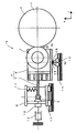
- the rolling resistance measuring apparatus of the tire of a 1st embodiment is shown, (a) is a top view and (b) is a front view. It is a top view of the rolling resistance measuring apparatus of the tire of a 2nd embodiment. It is a front view of the rolling resistance measuring apparatus of the tire of a 3rd embodiment. It is a front view of the rolling resistance measuring apparatus of the tire of a 4th embodiment.
- the rolling resistance measuring apparatus of the tire of a prior art example is shown, (a) is a top view, (b) is a front view.
- a tire rolling resistance measuring device 1 (hereinafter simply referred to as a device 1) of the present invention will be described with reference to the drawings.
- the left side of FIG. 1A is referred to as “left side”
- the right side of FIG. 1A is referred to as “right side”.
- the upper side of FIG. 1A is referred to as “rear side” and the lower side of FIG. 1A is referred to as “front side”.
- the upper side of FIG. 1B is referred to as “upper side”
- the lower side of FIG. 1B is referred to as “lower side”.
- the direction indicated by the arrow x is “up / down direction”
- the direction indicated by the arrow y is “front / rear direction”
- the direction indicated by the arrow z is “left / right direction”.
- the apparatus 1 includes a cylindrical drum 3 having a running simulation road surface 2 on which the tire T travels, provided on the outer peripheral surface, a carriage 4 that rotatably holds the tire T, and a carriage 4 that is swingably supported. And a load applying base 5 to be arranged side by side in the left-right direction.
- the load application base 5 is disposed adjacent to the left side of the carriage 4 and connected to the carriage 4. By moving the load application base 5 in the left-right direction, the tire T held by the carriage 4 can be pressed against the endless traveling simulation road surface 2.
- the drum 3 is attached to the right side of the device 1 so as to be rotatable around an axis along the front-rear direction of the device 1.
- the drum 3 is rotatable by a motor (not shown), and an endless traveling simulation road surface 2 on which the tire T rolls is formed on the outer peripheral surface thereof.
- the carriage 4 is disposed adjacent to the left side of the drum 3 (one end side of the carriage 4).
- the carriage 4 is disposed on the left side of the carriage body 6 (the other end side of the carriage 4) and rotatably connects the carriage body 6 to the load application base 5.
- the carriage body 6 is formed in a structure having excellent rigidity, for example, a structure in which three plate members arranged in the front-rear direction, the left-right direction, and the up-down direction are combined orthogonally to each other as in the present embodiment. Thereby, the carriage body 6 is formed so as not to be deformed when a load is applied to the tire T or when a load is applied from the tire T.
- a tire spindle 8 to which a tire T can be attached is mounted on the carriage body 6 with its axis oriented in the front-rear direction so that the tire T can be rotatably held in a vertical plane along the top, bottom, left, and right. It has become.
- the tire spindle 8 is arranged so that the rotation axis of the held tire T has the same height as the rotation axis of the drum 3 in the vertical direction, and moves the carriage 4 (carriage body 6) in the horizontal direction. Then, the tire T comes into contact with the running simulation road surface 2 of the drum 3 from the normal direction.
- the connecting member 7 is a plate member that connects the carriage body 6 and the load application base 5.
- a rocking shaft portion 9 facing in the left-right direction is provided at the distal end edge of the connecting member 7.
- the connecting member 7 is connected to the load application base 5 via a swing shaft portion 9 so as to be swingable about a shaft (swing shaft) directed in the left-right direction.
- the oscillating shaft portion 9 is provided with connecting means for minimizing rotational friction and preventing moment from being transmitted, for example, connecting means (hinge) for elastically connecting using a ball bearing or the like as in the present embodiment. It is used.
- connecting means such as a ball bearing for the swing shaft portion 9 so that the influence of the moment is not added to the measurement result of the rolling resistance.
- the rotating shaft of the drum 3 described above, the rotating shaft of the tire T (tire spindle 8), the swing shaft portion 9, and the connecting member 7 are all provided at the same height in the vertical direction. All are deployed to move within the same horizontal plane.
- the load application base 5 is provided on the left side of the carriage 4 and has a structure having excellent rigidity similar to the carriage 4, for example, three plate members provided along the front-rear direction, the left-right direction, and the up-down direction as in the present embodiment. It is formed in a structure that is combined orthogonally. As described above, the load application base 5 is formed so as not to be deformed when a load is applied to the tire T or when a load is applied from the tire T.
- the linear guide 11 is arranged along the left-right direction below the load application base 5, and the load application base 5 can be horizontally moved along the linear guide 11 in the left-right direction.
- a pressing load measuring unit 12 (a load cell for the pressing load Fz) that measures a load applied to the tire T from the load application stand 5, and the load application stand via the pressing load measurement unit 12.
- pressing means 13 for pressing 5 in the horizontal direction On the left side surface of the load application stand 5, a pressing load measuring unit 12 (a load cell for the pressing load Fz) that measures a load applied to the tire T from the load application stand 5, and the load application stand via the pressing load measurement unit 12.
- pressing means 13 for pressing 5 in the horizontal direction On the left side surface of the load application stand 5, a pressing load measuring unit 12 (a load cell for the pressing load Fz) that measures a load applied to the tire T from the load application stand 5, and the load application stand via the pressing load measurement unit 12.
- pressing means 13 for pressing 5 in the horizontal direction On the left side surface of the load application stand 5, a pressing
- the pressing means 13 of the present embodiment uses a hydraulic cylinder, but the pressing means 13 may be a ball screw or other telescopic load generating device in addition to the hydraulic cylinder. Moreover, the position to which the pressing means 13 is attached may not be on the axial center between the drum 3 and the tire T as long as the load applying base 5 can be pressed in the left-right direction.
- the carriage A weight of 4 is measured.
- the rolling resistance measuring unit 10 that measures the rolling resistance Fx from the force applied to the carriage 4 along the tangential direction of the tire T is provided so as to be movable along the moving direction of the load applying frame 5. It has been. In this way, the rolling resistance measuring unit 10 can be moved in the same direction in accordance with the movement of the load applying gantry 5, and the load applying gantry 5 on which the carriage 4 is supported and the rolling resistance measuring unit 10 are relative to each other. A pressing load can be applied to the tire T while maintaining a proper positional relationship. Thereby, since the weight of the carriage 4 acting on the rolling resistance measuring unit 10 does not change, an accurate rolling resistance Fx can be obtained.
- the rolling resistance measuring unit 10 is a compression load cell similar to the pressing load measuring unit 12, and measures a force acting in the vertical direction (y direction) from the carriage body 6 placed on the upper side.
- a linear guide unit 14 is provided in the same manner as the load application base 5, and along this linear guide unit 14, the rolling resistance measurement unit 10 can move horizontally in the left-right direction. is there.
- a projection 15 formed in a spherical shape toward the upper end side (carriage 4 side) is formed on the upper surface of the rolling resistance measurement unit 10, and the rolling resistance measurement unit 10 is vertically moved to the projection 15. It is configured to measure the force (load).
- a load receiving seat 16 that comes into contact with the protrusion 15 of the rolling resistance measuring unit 10 is provided substantially in the middle in the front-rear direction.
- the lower surface of the load receiving seat 16 is formed in a concave shape that is recessed upward, and has a spherical shape with a larger radius of curvature than the spherical surface formed at the protruding end of the protruding portion 15. In this way, if the protrusion 15 and the load seat 16 are formed in a spherical shape, both come into contact with each other via one point on the spherical surface, and a moment force does not act on the rolling resistance measuring unit 10. It is possible to accurately measure the rolling resistance Fx.
- the rolling resistance measurement unit 10 connected to the load receiving seat 16 of the carriage 4 by the projection 15 is moved along the linear guide part 14. Move horizontally to match. As a result, the amount of movement of the rolling resistance measuring unit 10 and the amount of movement of the load applying gantry 5 are the same, and the horizontal distance L ′ from the swing shaft 9 provided on the load applying gantry 5 to the rolling resistance measuring unit 10 is constant. The rolling resistance measuring unit 10 and the load application platform 5 are moved in the same direction.
- the rolling resistance measuring unit 10 is a compression load cell, and when the rolling resistance Fx is measured, the zero point adjustment is performed in advance before the tire T comes into contact with the drum 3. And in this rolling resistance measurement part 10, apparent rolling resistance Fx 'is measured.
- the true rolling resistance Fx generated at the contact point between the tire T and the drum 3 includes the horizontal distance L ′ from the swing shaft portion 9 to the rolling resistance measuring portion 10, the apparent rolling resistance Fx ′, and the swing shaft portion. Based on the following formula (1), the distance L from 9 to the ground contact portion between the tire T and the drum 3 can be calculated.
- the protrusion 15 having the protrusion formed in a spherical shape is provided in the rolling resistance measuring section 10 and the load receiving seat 16 of the carriage 4 that contacts the protrusion 15 is formed in a spherical shape, thereby applying a load.
- the rolling resistance measuring unit 10 moves in the left-right direction in accordance with the movement of the gantry 5 (carriage 4), and the relative distance between the rotation axis of the tire T and the carriage 4 and the rolling resistance measuring unit 10 is always constant. Therefore, even if the position of the center of gravity of the carriage 4 changes according to the position of the tire T, the rate at which the weight of the carriage 4 acts on the measurement value measured by the rolling resistance measurement unit 10 does not change significantly. Therefore, an accurate rolling resistance Fx is required.
- the carriage 4 moves in the front-rear direction even when a lateral force is generated on the tire T. There is no. Therefore, the force (Fy) acting in the direction of the rotation axis from the tire T is not added to the measurement value measured by the rolling resistance measuring unit 10, and only the rolling resistance Fx can be accurately obtained. Further, the closer to the drum 3 the place where the rolling resistance measuring unit 10 is arranged, the larger the apparent rolling resistance Fx ′ that can be measured, and the higher the rolling resistance Fx can be measured. .
- the apparatus 1a of 2nd Embodiment is demonstrated.
- the apparatus 1a of the second embodiment is different from the first embodiment in that the rolling resistance measuring units 10a and 10b are arranged on the lower side of the carriage 4 one by one in the front and rear.
- the load applied from 4 is a point measured by these two rolling resistance measuring units 10a and 10b.
- the load receiving seats 16 are provided at positions that are line-symmetric with respect to the center line C along the left-right direction passing through the contact point between the tire T and the drum 3. It has been. Then, a pair of front and rear rolling resistance measuring units 10a and 10b are provided so that the protrusion 15 is brought into contact with the lower side of each load receiving seat 16.
- the weight of the carriage 4 can be divided into two parts and supported by the pair of rolling resistance measuring units 10a and 10b.
- the two rolling resistance measuring units 10a and 10b are arranged so that one of the rolling resistance measuring units does not float away from the load seat 16, and It is desirable to adjust the height so that the weight of the carriage 4 is shared approximately by half.
- Other configurations and operational effects in the second embodiment are the same as those in the first embodiment.
- the apparatus 1b of 3rd Embodiment is demonstrated.
- the apparatus 1 b of the third embodiment is different from the first embodiment in that the carriage 4 is provided with its own weight reducing means 17 for reducing the own weight of the carriage 4 applied to the rolling resistance measuring unit 10. It is a point.
- the connecting member 7 of the carriage 4 and the load application base 5 are connected by the own weight reducing means 17, and the own weight reducing means 17 is connected to the rolling resistance measuring unit 10.
- the weight of the acting carriage 4 can be reduced.
- the self-weight reducing means 17 is, for example, a tension spring with a pretension. This spring is adjusted such that the rigidity is as small as possible than the spring rigidity (support rigidity) of the rolling resistance measuring unit 10 at the position where the rolling resistance measuring unit 10 is installed.
- the spring stiffness of the rolling resistance measuring unit 10 is k
- the distance from the swing shaft 9 to the rolling resistance measuring unit 10 is L ′
- the distance from the swing shaft 9 to the own weight reducing means 17 is L ′′.
- a spring having a rigidity smaller than k ⁇ L ′′ / L ′ can be used as the self-weight reducing means 17.
- the apparatus 1 b using the self-weight reducing means 17 a part of the weight of the carriage 4 is supported by the self-weight reducing means 17. Therefore, a load applied to the rolling resistance measurement unit 10 is reduced, and a load cell having a small measurement range, in other words, a load cell with high measurement accuracy can be used for the rolling resistance measurement unit 10. Further, in the apparatus 1b, by performing calibration of the rolling resistance measuring unit 10, a spring having a certain degree of rigidity is required to support the weight of the carriage 4 in the rolling resistance measuring unit 10. In addition, the rolling resistance measurement unit 10 can measure the rolling resistance of the tire T with high accuracy. Furthermore, since a load cell with a small load capacity is often inexpensive, if a load cell with a small load capacity can be used for the rolling resistance measuring unit 10, the manufacturing cost of the device 1b can be reduced.
- this spring when the tire T and the drum 3 are configured to rotate in a horizontal plane, this spring can also be used as a means for applying a pressing load to the rolling resistance measuring unit 10, A compression type load cell can be used for the rolling resistance measuring unit 10. Further, in the device 1b, the tire T and the drum 3 can be configured to rotate in a horizontal plane, or the tire T and the drum 3 are arranged in the vertical direction as in a fourth embodiment (FIG. 4) described later. It can be configured to measure the rolling resistance Fx with one load cell on one side.
- the rolling resistance measuring unit 10 and the carriage 4 are pin-coupled, and a compression tension type load cell capable of measuring the load in the compressing direction and the load in the pulling direction is used for the rolling resistance measuring unit 10. It is possible to adopt a configuration to In such a case, it is not necessary to provide a spring. Other configurations and operational effects in the third embodiment are the same as those in the first embodiment.
- the apparatus 1c of 4th Embodiment is demonstrated.
- the load application base 5, the carriage 4 holding the tire T, and the drum 3 having the traveling simulation road surface 2 are arranged in the vertical direction.
- the carriage 4 to which the tire T is attached is configured to approach and separate in the vertical direction with respect to the drum 3.
- the difference of the device 1c of the fourth embodiment from the first to third embodiments is that it occurs in the horizontal direction (left and right in the example) from the tire T pressed in the vertical direction against the running simulation road surface 2.
- the rolling resistance Fx is configured to be measured by the rolling resistance measuring unit 10.
- the load application base 5 is disposed below the pressing means 13 provided in a suspended manner on a frame or the like.
- the load application base 5 is guided by a linear guide 11 provided on the left side of the load application base 5 along the vertical direction so as to be movable in the vertical direction.
- the carriage 4 provided below the load application base 5 is also guided to be movable in the vertical direction by a pair of left and right linear guide portions 14 arranged along the vertical direction on the right and left sides of the carriage 4. Yes.
- a rolling resistance measuring unit 10 is provided between the pair of left and right linear guide units 14 and the carriage 4, and the rolling resistance Fx applied to the carriage 4 generated in the forward / reverse direction of the tire T in the left / right direction. Can be measured.
- the present invention is not limited to the above-described embodiments, and the shape, structure, material, combination, and the like of each member can be appropriately changed without changing the essence of the present invention.
- the apparatus by which the tire T is pressed on the drum 3 by which the driving
- the apparatus may be configured such that, for example, an endless belt having a traveling simulation road surface 2 formed on the surface is used, and the tire T is pressed against the surface of the belt.
- the connecting member 7 that connects the load applying base 5 and the carriage body 6 is formed in a plate shape.
- the connecting member 7 may have a rod shape, for example, and ribs are provided on the surface of the connecting member 7 so as not to be deformed by a moment (Mz) around the tire axis (z axis) generated in the tire T. May be.
- the carriage 4 and the rolling resistance measuring unit 10 are connected by the load receiving seat 16 formed in a concave shape on the carriage 4 side and the projection 15 formed in a spherical shape on the rolling resistance measuring unit 10 side. What has been illustrated is illustrated.
- the carriage 4 and the rolling resistance measuring unit 10 may be pin-coupled, for example, or provided with a concave seat on the rolling resistance measuring unit 10 side and formed in a spherical shape on the carriage 4 side. A protrusion may be provided.
Landscapes
- Physics & Mathematics (AREA)
- General Physics & Mathematics (AREA)
- Tires In General (AREA)
Abstract
Description
転がり抵抗Fxを測定する方法としては、ドラム式のタイヤ走行試験機による方法が代表的である。ドラム式のタイヤ走行試験機は、走行ドラムの外周に形成された走行模擬路面に試験用のタイヤを押圧状態で接触させて、このタイヤを支持するタイヤスピンドル軸部に設けられた多分力検出器(ロードセル)によって、押し付け荷重Fzと転がり抵抗Fxとの関係を測定する。
また、タイヤの荷重発生部(走行模擬路面との接地部)と多分力計とはオフセットした位置に取り付けられることが多いため、転がり抵抗Fxの実測値には、押し付け荷重Fzだけでなくタイヤに発生する横力に起因するモーメントカがクロストーク誤差として加わる。転がり抵抗Fxと押し付け荷重Fz以外の各種成分を合わせて計測することにより、誤差を補正して転がり抵抗Fxの計測精度を高める技術も提案されているが、高価な多分力計が必要となることからタイヤ走行試験機の価格を高騰させやすい。また、クロストークによる誤差には非線形成分が含まれているため、十分な補正は実際には困難である。
即ち、本発明は、無端の走行模擬路面にタイヤを押し付けることにより該タイヤの転がり抵抗を測定する、タイヤの転がり抵抗測定装置であって、前記タイヤを回転自在に保持するタイヤスピンドルを一端側に搭載するキャリッジと、前記キャリッジの他端側を前記タイヤの回転軸と平行な揺動軸回りに揺動自在に連結するとともに、前記揺動軸の軸心が前記走行模擬路面に対するタイヤの接地点とタイヤの回転中心とを結ぶ延長線上に位置するように前記キャリッジを前記走行模擬路面側へ動かすことにより前記タイヤスピンドルに保持された前記タイヤに荷重を付与する荷重付与架台と、前記荷重付与架台から前記タイヤに加えられた荷重を計測する押し付け荷重計測部と、前記タイヤの接線方向に沿って前記キャリッジに加えられた力から前記タイヤの転がり抵抗を計測する転がり抵抗計測部と、を有しており、前記転がり抵抗計測部は、前記荷重付与架台の移動方向に沿って移動可能であることを特徴とする。
それゆえ、上述のタイヤの転がり抵抗測定装置によれば、クロストーク誤差の影響を排除して、転がり抵抗を精度良く計測することができる。また、このような装置においては、転がり抵抗計測部に廉価な単軸ロードセルを用いることができるので、安価な装置が実現可能となる。
また、上述のように、転がり抵抗Fxを計測する転がり抵抗計測部と、タイヤに加えられる荷重を計測する押し付け荷重計測部とが別々に設けられている構成では、転がり抵抗の計測値に比べてキャリッジの自重の方が大きい場合が多い。そのため、転がり抵抗計測部に負荷容量の大きなロードセルを用いる必要があるが、負荷容量の大きなロードセルは、必然的に計測分解能が悪い。それゆえ、前記キャリッジは、前記転がり抵抗計測部に加えられる前記キャリッジの自重を低減する自重低減手段を有することが好ましい。
以下、本発明のタイヤの転がり抵抗測定装置1(以下、単に装置1という)を図面に基づき説明する。
以下の説明において、図1(a)の左側を「左側」、図1(a)の右側を「右側」とする。図1(a)の上側を装置1を「後側」、図1(a)の下側を「前側」とする。また、図1(b)の上側を「上側」、図1(b)の下側を「下側」とする。さらに、図中、xの矢印で示される方向を「上下方向」、yの矢印で示される方向を「前後方向」、zの矢印で示される方向を「左右方向」とする。
ドラム3は、装置1の前後方向に沿った軸の回りを回転自在なように、装置1の右側に取り付けられている。ドラム3は、図示を省略するモータにより回転自在とされており、その外周面にはタイヤTを転動させる無端の走行模擬路面2が形成されている。
キャリッジ本体6は、剛性に優れた構造、例えば本実施形態のように前後方向、左右方向及び上下方向に沿って配備された3つの板材を互いに直交状に組み合わせた構造に形成されている。これにより、キャリッジ本体6は、タイヤTに荷重を加える際やタイヤTから荷重が加わった際に変形しないように形成されている。
荷重付与架台5は、キャリッジ4の左側に配備され、キャリッジ4同様に剛性に優れた構造、例えば本実施形態のように前後方向、左右方向及び上下方向に沿って配備された3つの板材を互いに直交状に組み合わせた構造に形成されている。このように荷重付与架台5は、タイヤTに荷重を加える際やタイヤTから荷重が加わった際に変形しないように形成されている。
ところで、上述のように荷重付与装置1を動かしてタイヤTをドラム3に対して水平に押し付ける構成(従来の装置構成)では、転がり抵抗計測部10で計測される転がり抵抗の荷重に加えてキャリッジ4の自重が計測される。ところが、転がり抵抗を計測する際は押し付け荷重を変化させるため、押し付け荷重に応じてドラム3に対するタイヤTの位置が変化し、キャリッジ4全体の重心位置も変化する。それゆえ、転がり抵抗計測部10で計測される荷重計測結果に、このキャリッジ4の重心移動に起因するモーメントが作用するため、転がり抵抗Fxを精度良く計測することが困難である。
転がり抵抗計測部10は、押し付け荷重計測部12と同様な圧縮用のロードセルであり、上側に載せられたキャリッジ本体6から上下方向(y方向)に沿って作用する力を計測する。転がり抵抗計測部10の下側には、荷重付与架台5と同様にリニアガイド部14が配備されており、このリニアガイド部14に沿って、転がり抵抗計測部10は左右方向に水平移動可能である。また、転がり抵抗計測部10の上面には上端側(キャリッジ4側)に向けて球面状に形成された突起部15が形成されており、転がり抵抗計測部10はこの突起部15に加わる上下方向の力(荷重)を計測するよう構成されている。
このように、突起部15と荷重受座16とを互いに球面状に形成すれば、球面上の1点を介して両者が互いに当接し、転がり抵抗計測部10にモーメント力が作用することなく、転がり抵抗Fxを精度良く計測することができる。
タイヤTに押し付け荷重Fzを付与する際は、上述したように押圧手段13を用いて荷重付与架台5を右側に向かって押圧して、荷重付与架台5をリニアガイド11に沿って水平方向に移動させる。そうすると、揺動軸部9を介して荷重付与架台5の右側に連結されたキャリッジ4が右側に向かって移動し、揺動軸の軸心が走行模擬路面2に対するタイヤTの接地点とタイヤTの回転中心とを結ぶ延長線上に位置するようになる。
一方、転がり抵抗計測部10は圧縮用のロードセルであり、転がり抵抗Fxを計測する際には、タイヤTがドラム3と接触する前に予めゼロ点調整が行われている。そして、この転がり抵抗計測部10では、見かけの転がり抵抗Fx’が計測される。
また、転がり抵抗計測部10を配置する場所がドラム3に近いほど、計測される見かけの転がり抵抗Fx’を大きくすることができ、転がり抵抗Fxを高精度に計測することができるため有利である。
次に、第2実施形態の装置1aについて説明する。
図2に示されるように、第2実施形態の装置1aが第1実施形態と異なる点は、転がり抵抗計測部10a、10bがキャリッジ4の下側に前後に1組ずつ配備されており、キャリッジ4から加わる荷重がこれら2箇所の転がり抵抗計測部10a、10bにより計測される点である。
なお、2つの転がり抵抗計測部が設けられる場合には、一方の転がり抵抗計測部が荷重受座16から離れて浮いてしまうことが無いように、また、2つの転がり抵抗計測部10a、10bが、キャリッジ4の自重をほぼ半分ずつ分担するように高さ調整を行うことが望ましい。
第2実施形態におけるその他の構成や作用効果は、第1実施形態と同じである。
次に、第3実施形態の装置1bについて説明する。
図3に示されるように、第3実施形態の装置1bが第1実施形態と異なる点は、転がり抵抗計測部10に加わるキャリッジ4の自重を低減する自重低減手段17が、キャリッジ4に備えられている点である。
また、装置1bにおいて、タイヤTとドラム3とは水平面内で回転するように構成可能であり、または後述する第4実施形態(図4)のように、タイヤTとドラム3とが垂直方向に配備されて片側1個のロードセルで転がり抵抗Fxを計測するように構成可能である。このような場合には、例えば転がり抵抗計測部10とキャリッジ4とをピン結合すると共に、転がり抵抗計測部10に、圧縮方向の荷重も引っ張り方向の荷重も計測可能な圧縮引っ張り型のロードセルを使用する構成が採用可能である。このような場合には、特にバネを設ける必要は無い。
第3実施形態におけるその他の構成や作用効果は、第1実施形態と同じである。
次に、第4実施形態の装置1cについて説明する。
図4に示されるように、第4実施形態の装置1cでは、荷重付与架台5と、タイヤTを保持したキャリッジ4と、及び走行模擬路面2を備えたドラム3と、が上下方向に並んで配備されている。タイヤTが取り付けられたキャリッジ4は、ドラム3に対して垂直方向に近接離反するように構成されている。そして、第4実施形態の装置1cが第1実施形態~第3実施形態と異なる点は、走行模擬路面2に垂直方向に押し付けられたタイヤTから水平方向(図例では左右方向)に発生する転がり抵抗Fxが、転がり抵抗計測部10により計測されるよう構成されている点である。
上記実施形態では、外周面に走行模擬路面2が形成されたドラム3に、タイヤTが押し付けられる装置が例示されている。しかし、例えば表面に走行模擬路面2が形成された無端のベルトを用いて、このベルトの表面にタイヤTが押し付けられるように装置が構成されても良い。
2 走行模擬路面
3 ドラム
4 キャリッジ
5 荷重付与架台
6 キャリッジ本体
7 連結部材
8 タイヤスピンドル
9 揺動軸部
10、10a、10b 転がり抵抗計測部
11 リニアガイド
12 押し付け荷重計測部
13 押圧手段
14 リニアガイド部
15 突起部
16 荷重受座
17 自重低減手段
C 中心線
Fx 転がり抵抗
Fz 押し付け荷重
T タイヤ
Claims (4)
- 無端の走行模擬路面にタイヤを押し付けることにより該タイヤの転がり抵抗を測定する、タイヤの転がり抵抗測定装置であって、
前記タイヤを回転自在に保持するタイヤスピンドルを一端側に搭載するキャリッジと、
前記キャリッジの他端側を前記タイヤの回転軸と平行な揺動軸回りに揺動自在に連結するとともに、前記揺動軸の軸心が前記走行模擬路面に対するタイヤの接地点とタイヤの回転中心とを結ぶ延長線上に位置するように前記キャリッジを前記走行模擬路面側へ動かすことにより前記タイヤスピンドルに保持された前記タイヤに荷重を付与する荷重付与架台と、
前記荷重付与架台から前記タイヤに加えられた荷重を計測する押し付け荷重計測部と、
前記タイヤの接線方向に沿って前記キャリッジに加えられた力から前記タイヤの転がり抵抗を計測する転がり抵抗計測部と、を有しており、
前記転がり抵抗計測部は、前記荷重付与架台の移動方向に沿って移動可能であることを特徴とするタイヤの転がり抵抗測定装置。 - 前記転がり抵抗計測部の移動量と前記荷重付与架台の移動量とが同じになるように構成されていることを特徴とする請求項1に記載のタイヤの転がり抵抗測定装置。
- 前記キャリッジは、前記転がり抵抗計測部に加えられる前記キャリッジの自重を低減する自重低減手段を有することを特徴とする請求項1又は2に記載のタイヤの転がり抵抗測定装置。
- 前記転がり抵抗計測部が突起部を有し、前記突起部の先端が前記キャリッジに向かって球面状に形成されており、前記キャリッジが前記突起部の先端と当接する凹面状の荷重受座を有することを特徴とする請求項2に記載のタイヤの転がり抵抗測定装置。
Priority Applications (1)
| Application Number | Priority Date | Filing Date | Title |
|---|---|---|---|
| CN2010800102734A CN102341688B (zh) | 2009-03-03 | 2010-03-02 | 轮胎滚动阻力测定装置 |
Applications Claiming Priority (2)
| Application Number | Priority Date | Filing Date | Title |
|---|---|---|---|
| JP2009049561A JP5011328B2 (ja) | 2009-03-03 | 2009-03-03 | タイヤの転がり抵抗測定装置 |
| JP2009-049561 | 2009-03-03 |
Publications (1)
| Publication Number | Publication Date |
|---|---|
| WO2010101159A1 true WO2010101159A1 (ja) | 2010-09-10 |
Family
ID=42709715
Family Applications (1)
| Application Number | Title | Priority Date | Filing Date |
|---|---|---|---|
| PCT/JP2010/053364 Ceased WO2010101159A1 (ja) | 2009-03-03 | 2010-03-02 | タイヤの転がり抵抗測定装置 |
Country Status (3)
| Country | Link |
|---|---|
| JP (1) | JP5011328B2 (ja) |
| CN (1) | CN102341688B (ja) |
| WO (1) | WO2010101159A1 (ja) |
Cited By (7)
| Publication number | Priority date | Publication date | Assignee | Title |
|---|---|---|---|---|
| WO2012081525A1 (ja) * | 2010-12-15 | 2012-06-21 | 株式会社神戸製鋼所 | 転がり抵抗試験機に備えられた多分力検出器の校正方法 |
| WO2012086547A1 (ja) * | 2010-12-24 | 2012-06-28 | 株式会社神戸製鋼所 | 転がり抵抗試験機に備えられた多分力検出器の校正方法 |
| WO2013191055A1 (ja) * | 2012-06-20 | 2013-12-27 | 株式会社神戸製鋼所 | 転がり抵抗試験機に備えられた多分力検出器の校正方法 |
| EP3093642A4 (en) * | 2014-01-24 | 2017-09-27 | Sumitomo Rubber Industries, Ltd. | Tire rolling-resistance testing method and testing device |
| CN108007702A (zh) * | 2018-01-22 | 2018-05-08 | 中国重型机械研究院股份公司 | 一种轮胎的动力与刹车试验台侧向加载机构 |
| EP3517926A4 (en) * | 2016-09-20 | 2020-05-06 | Kabushiki Kaisha Kobe Seiko Sho (Kobe Steel, Ltd.) | DEVICE FOR EVALUATING THE BEARING RESISTANCE OF A TIRE |
| US10775272B2 (en) * | 2017-12-05 | 2020-09-15 | Ali Samadi | Rubber footprint and rolling resistance measurement |
Families Citing this family (7)
| Publication number | Priority date | Publication date | Assignee | Title |
|---|---|---|---|---|
| JP5735903B2 (ja) * | 2010-11-29 | 2015-06-17 | 住友ゴム工業株式会社 | 車輪体を用いたタイヤの転がり抵抗測定方法 |
| KR101300002B1 (ko) | 2010-12-15 | 2013-09-10 | 한국타이어 주식회사 | 타이어 회전저항 측정 시스템 및 방법 |
| CN103471862A (zh) * | 2013-09-20 | 2013-12-25 | 华东交通大学 | 单滚筒在整车状态下测量轮胎滚动阻力的方法 |
| CN103759954B (zh) * | 2014-02-25 | 2016-02-17 | 吉林大学 | 一种轮胎滚动阻力精确测试的方法及装置 |
| JP6412437B2 (ja) * | 2014-05-12 | 2018-10-24 | 株式会社神戸製鋼所 | タイヤの転がり抵抗予測手法およびタイヤの転がり抵抗予測装置 |
| JP6349271B2 (ja) * | 2015-02-26 | 2018-06-27 | 株式会社神戸製鋼所 | タイヤ試験機の押圧荷重設定方法 |
| JP6673739B2 (ja) * | 2016-04-15 | 2020-03-25 | 株式会社神戸製鋼所 | タイヤの転がり抵抗の評価装置及び評価方法 |
Citations (4)
| Publication number | Priority date | Publication date | Assignee | Title |
|---|---|---|---|---|
| JPS5461592A (en) * | 1977-10-25 | 1979-05-17 | Kobe Steel Ltd | Method and device for measuring rolling resistance of tire |
| JPS5546150A (en) * | 1978-09-28 | 1980-03-31 | Yamato Scale Co Ltd | Tester for rotary body |
| US4956995A (en) * | 1990-01-16 | 1990-09-18 | Navistar International Transportation Corp. | Compact radial force measuring apparatus for determining variations in radial force around a tire and rim assembly |
| JP2007121160A (ja) * | 2005-10-28 | 2007-05-17 | Kobe Steel Ltd | タイヤ走行試験機 |
Family Cites Families (3)
| Publication number | Priority date | Publication date | Assignee | Title |
|---|---|---|---|---|
| CN2341138Y (zh) * | 1998-10-07 | 1999-09-29 | 汕头市科技咨询服务公司橡塑机械研究所 | 一种车辆轮胎耐久性试验机 |
| JP4015095B2 (ja) * | 2003-10-21 | 2007-11-28 | 株式会社神戸製鋼所 | タイヤ試験装置 |
| JP2008082709A (ja) * | 2006-09-25 | 2008-04-10 | Sumitomo Rubber Ind Ltd | タイヤ性能測定装置およびレース用タイヤの性能測定方法 |
-
2009
- 2009-03-03 JP JP2009049561A patent/JP5011328B2/ja not_active Expired - Fee Related
-
2010
- 2010-03-02 WO PCT/JP2010/053364 patent/WO2010101159A1/ja not_active Ceased
- 2010-03-02 CN CN2010800102734A patent/CN102341688B/zh not_active Expired - Fee Related
Patent Citations (4)
| Publication number | Priority date | Publication date | Assignee | Title |
|---|---|---|---|---|
| JPS5461592A (en) * | 1977-10-25 | 1979-05-17 | Kobe Steel Ltd | Method and device for measuring rolling resistance of tire |
| JPS5546150A (en) * | 1978-09-28 | 1980-03-31 | Yamato Scale Co Ltd | Tester for rotary body |
| US4956995A (en) * | 1990-01-16 | 1990-09-18 | Navistar International Transportation Corp. | Compact radial force measuring apparatus for determining variations in radial force around a tire and rim assembly |
| JP2007121160A (ja) * | 2005-10-28 | 2007-05-17 | Kobe Steel Ltd | タイヤ走行試験機 |
Cited By (17)
| Publication number | Priority date | Publication date | Assignee | Title |
|---|---|---|---|---|
| US9618416B2 (en) | 2010-12-15 | 2017-04-11 | Kobe Steel, Ltd. | Method of calibrating multi component force detector provided in rolling resistance testing machine |
| JP2012127785A (ja) * | 2010-12-15 | 2012-07-05 | Kobe Steel Ltd | 転がり抵抗試験機に備えられた多分力検出器の校正方法 |
| WO2012081525A1 (ja) * | 2010-12-15 | 2012-06-21 | 株式会社神戸製鋼所 | 転がり抵抗試験機に備えられた多分力検出器の校正方法 |
| WO2012086547A1 (ja) * | 2010-12-24 | 2012-06-28 | 株式会社神戸製鋼所 | 転がり抵抗試験機に備えられた多分力検出器の校正方法 |
| JP2012137321A (ja) * | 2010-12-24 | 2012-07-19 | Kobe Steel Ltd | 転がり抵抗試験機に備えられた多分力検出器の校正方法 |
| US9645024B2 (en) | 2010-12-24 | 2017-05-09 | Kobe Steel, Ltd. | Method of calibrating multi component force detector provided in rolling resistance testing machine |
| TWI448676B (zh) * | 2010-12-24 | 2014-08-11 | Kobe Steel Ltd | Calibration method of multi - force detector based on rolling resistance testing machine |
| WO2013191055A1 (ja) * | 2012-06-20 | 2013-12-27 | 株式会社神戸製鋼所 | 転がり抵抗試験機に備えられた多分力検出器の校正方法 |
| KR101622869B1 (ko) | 2012-06-20 | 2016-05-19 | 가부시키가이샤 고베 세이코쇼 | 구름 저항 시험기에 구비된 다분력 검출기의 교정 방법 |
| JP2014002079A (ja) * | 2012-06-20 | 2014-01-09 | Kobe Steel Ltd | 転がり抵抗試験機に備えられた多分力検出器の校正方法 |
| US9791344B2 (en) | 2012-06-20 | 2017-10-17 | Kobe Steel, Ltd. | Calibration method for multi-component force detector provided in rolling resistance testing machine |
| EP3093642A4 (en) * | 2014-01-24 | 2017-09-27 | Sumitomo Rubber Industries, Ltd. | Tire rolling-resistance testing method and testing device |
| US9885637B2 (en) | 2014-01-24 | 2018-02-06 | Sumitomo Rubber Industries, Ltd. | Tire rolling resistance testing method and testing device |
| EP3517926A4 (en) * | 2016-09-20 | 2020-05-06 | Kabushiki Kaisha Kobe Seiko Sho (Kobe Steel, Ltd.) | DEVICE FOR EVALUATING THE BEARING RESISTANCE OF A TIRE |
| US10775272B2 (en) * | 2017-12-05 | 2020-09-15 | Ali Samadi | Rubber footprint and rolling resistance measurement |
| CN108007702A (zh) * | 2018-01-22 | 2018-05-08 | 中国重型机械研究院股份公司 | 一种轮胎的动力与刹车试验台侧向加载机构 |
| CN108007702B (zh) * | 2018-01-22 | 2024-03-22 | 中国重型机械研究院股份公司 | 一种轮胎的动力与刹车试验台侧向加载机构 |
Also Published As
| Publication number | Publication date |
|---|---|
| CN102341688A (zh) | 2012-02-01 |
| CN102341688B (zh) | 2013-11-13 |
| JP2010203908A (ja) | 2010-09-16 |
| JP5011328B2 (ja) | 2012-08-29 |
Similar Documents
| Publication | Publication Date | Title |
|---|---|---|
| JP5011328B2 (ja) | タイヤの転がり抵抗測定装置 | |
| JP2823579B2 (ja) | タイヤユニフォーミティ測定装置 | |
| JP5011361B2 (ja) | タイヤ試験機 | |
| JP4310365B1 (ja) | タイヤ試験機及びタイヤの試験方法 | |
| JP6781368B2 (ja) | シャシダイナモメータ | |
| US7908916B2 (en) | Flat belt roadway simulator with steer and/or camber adjustment and method for ascertaining rolling loss | |
| JP6095676B2 (ja) | 風洞天秤 | |
| JPS6357728B2 (ja) | ||
| CN102865970B (zh) | 具有用于确定轮胎均匀性的部件的车轮平衡机 | |
| CN107300474A (zh) | 汽车横向稳定杆耐久试验台架 | |
| JP2009180715A (ja) | タイヤ試験装置及びタイヤ試験方法 | |
| JP6722815B2 (ja) | 回転体荷重測定装置 | |
| JPH0481634A (ja) | 車両のホイールアライメント測定方法及びその装置 | |
| CN104057792A (zh) | 具有加载带设备的轮胎安装和拆卸设备 | |
| JPH0750002B2 (ja) | すべり摩擦力測定装置 | |
| CN115307925B (zh) | 一种汽车踏板机构静强度测试台架及测试方法 | |
| JP2013156232A (ja) | 車両拘束装置及び車両試験方法 | |
| KR102570929B1 (ko) | 상하이동식 슬립바를 포함하는 자동차 브레이크 테스터 장치 | |
| JP2011107163A (ja) | タイヤ試験システム用の振動補正システム | |
| JP2003194645A (ja) | 車輪の横力測定装置 | |
| JP2014232043A (ja) | タイヤ試験装置およびタイヤ試験方法 | |
| JP2005315882A (ja) | 車両のホイールアライメント調整方法 | |
| CN207019915U (zh) | 汽车横向稳定杆耐久试验台架 | |
| JPH0411815B2 (ja) | ||
| JP2018141710A (ja) | タイヤの試験装置 |
Legal Events
| Date | Code | Title | Description |
|---|---|---|---|
| WWE | Wipo information: entry into national phase |
Ref document number: 201080010273.4 Country of ref document: CN |
|
| 121 | Ep: the epo has been informed by wipo that ep was designated in this application |
Ref document number: 10748754 Country of ref document: EP Kind code of ref document: A1 |
|
| WWE | Wipo information: entry into national phase |
Ref document number: 6208/CHENP/2011 Country of ref document: IN |
|
| NENP | Non-entry into the national phase |
Ref country code: DE |
|
| 122 | Ep: pct application non-entry in european phase |
Ref document number: 10748754 Country of ref document: EP Kind code of ref document: A1 |