WO2010100943A1 - 太陽電池モジュール用保護シートおよびこれを用いた太陽電池モジュール - Google Patents
太陽電池モジュール用保護シートおよびこれを用いた太陽電池モジュール Download PDFInfo
- Publication number
- WO2010100943A1 WO2010100943A1 PCT/JP2010/001547 JP2010001547W WO2010100943A1 WO 2010100943 A1 WO2010100943 A1 WO 2010100943A1 JP 2010001547 W JP2010001547 W JP 2010001547W WO 2010100943 A1 WO2010100943 A1 WO 2010100943A1
- Authority
- WO
- WIPO (PCT)
- Prior art keywords
- solar cell
- cell module
- protective sheet
- layer
- sheet
- Prior art date
Links
- 230000001681 protective effect Effects 0.000 title claims abstract description 124
- 230000004888 barrier function Effects 0.000 claims abstract description 57
- 239000000463 material Substances 0.000 claims abstract description 20
- 229910052809 inorganic oxide Inorganic materials 0.000 claims abstract description 11
- 238000010248 power generation Methods 0.000 claims abstract description 11
- 239000010410 layer Substances 0.000 claims description 147
- 239000012790 adhesive layer Substances 0.000 claims description 80
- 238000007740 vapor deposition Methods 0.000 claims description 63
- 229920005989 resin Polymers 0.000 claims description 55
- 239000011347 resin Substances 0.000 claims description 55
- 239000011248 coating agent Substances 0.000 claims description 31
- 238000000576 coating method Methods 0.000 claims description 31
- YCKRFDGAMUMZLT-UHFFFAOYSA-N Fluorine atom Chemical compound [F] YCKRFDGAMUMZLT-UHFFFAOYSA-N 0.000 claims description 26
- 229910052731 fluorine Inorganic materials 0.000 claims description 26
- 239000011737 fluorine Substances 0.000 claims description 26
- 239000003973 paint Substances 0.000 claims description 19
- XLYOFNOQVPJJNP-UHFFFAOYSA-N water Chemical compound O XLYOFNOQVPJJNP-UHFFFAOYSA-N 0.000 claims description 19
- 230000035699 permeability Effects 0.000 claims description 13
- 239000000758 substrate Substances 0.000 claims description 11
- 230000007774 longterm Effects 0.000 abstract description 2
- 239000007789 gas Substances 0.000 description 50
- 239000000853 adhesive Substances 0.000 description 32
- 230000001070 adhesive effect Effects 0.000 description 32
- 238000001035 drying Methods 0.000 description 18
- VYPSYNLAJGMNEJ-UHFFFAOYSA-N Silicium dioxide Chemical compound O=[Si]=O VYPSYNLAJGMNEJ-UHFFFAOYSA-N 0.000 description 13
- 239000005038 ethylene vinyl acetate Substances 0.000 description 13
- -1 polyethylene Polymers 0.000 description 13
- ZWEHNKRNPOVVGH-UHFFFAOYSA-N 2-Butanone Chemical compound CCC(C)=O ZWEHNKRNPOVVGH-UHFFFAOYSA-N 0.000 description 12
- 229910044991 metal oxide Inorganic materials 0.000 description 12
- 229920001200 poly(ethylene-vinyl acetate) Polymers 0.000 description 12
- 239000002904 solvent Substances 0.000 description 12
- GWEVSGVZZGPLCZ-UHFFFAOYSA-N Titan oxide Chemical compound O=[Ti]=O GWEVSGVZZGPLCZ-UHFFFAOYSA-N 0.000 description 11
- DQXBYHZEEUGOBF-UHFFFAOYSA-N but-3-enoic acid;ethene Chemical compound C=C.OC(=O)CC=C DQXBYHZEEUGOBF-UHFFFAOYSA-N 0.000 description 11
- 230000000694 effects Effects 0.000 description 11
- 150000004706 metal oxides Chemical class 0.000 description 11
- 229920002799 BoPET Polymers 0.000 description 10
- 239000000049 pigment Substances 0.000 description 10
- 229920002635 polyurethane Polymers 0.000 description 9
- 239000004814 polyurethane Substances 0.000 description 9
- 238000000034 method Methods 0.000 description 8
- 229920000728 polyester Polymers 0.000 description 8
- 229920000642 polymer Polymers 0.000 description 8
- 239000002344 surface layer Substances 0.000 description 8
- BFKJFAAPBSQJPD-UHFFFAOYSA-N tetrafluoroethene Chemical group FC(F)=C(F)F BFKJFAAPBSQJPD-UHFFFAOYSA-N 0.000 description 8
- 239000000178 monomer Substances 0.000 description 7
- 239000000126 substance Substances 0.000 description 7
- JHIVVAPYMSGYDF-UHFFFAOYSA-N cyclohexanone Chemical compound O=C1CCCCC1 JHIVVAPYMSGYDF-UHFFFAOYSA-N 0.000 description 6
- 239000007788 liquid Substances 0.000 description 6
- 239000000377 silicon dioxide Substances 0.000 description 6
- BQCIDUSAKPWEOX-UHFFFAOYSA-N 1,1-Difluoroethene Chemical compound FC(F)=C BQCIDUSAKPWEOX-UHFFFAOYSA-N 0.000 description 5
- UUAGAQFQZIEFAH-UHFFFAOYSA-N chlorotrifluoroethylene Chemical group FC(F)=C(F)Cl UUAGAQFQZIEFAH-UHFFFAOYSA-N 0.000 description 5
- 230000000052 comparative effect Effects 0.000 description 5
- 239000003431 cross linking reagent Substances 0.000 description 5
- 239000000203 mixture Substances 0.000 description 5
- 239000003566 sealing material Substances 0.000 description 5
- XKRFYHLGVUSROY-UHFFFAOYSA-N Argon Chemical compound [Ar] XKRFYHLGVUSROY-UHFFFAOYSA-N 0.000 description 4
- 239000003054 catalyst Substances 0.000 description 4
- 238000010292 electrical insulation Methods 0.000 description 4
- 239000012948 isocyanate Substances 0.000 description 4
- TWNQGVIAIRXVLR-UHFFFAOYSA-N oxo(oxoalumanyloxy)alumane Chemical compound O=[Al]O[Al]=O TWNQGVIAIRXVLR-UHFFFAOYSA-N 0.000 description 4
- 229920002620 polyvinyl fluoride Polymers 0.000 description 4
- 229920001897 terpolymer Polymers 0.000 description 4
- 239000004408 titanium dioxide Substances 0.000 description 4
- CSCPPACGZOOCGX-UHFFFAOYSA-N Acetone Chemical compound CC(C)=O CSCPPACGZOOCGX-UHFFFAOYSA-N 0.000 description 3
- 239000004215 Carbon black (E152) Substances 0.000 description 3
- LFQSCWFLJHTTHZ-UHFFFAOYSA-N Ethanol Chemical compound CCO LFQSCWFLJHTTHZ-UHFFFAOYSA-N 0.000 description 3
- XEKOWRVHYACXOJ-UHFFFAOYSA-N Ethyl acetate Chemical compound CCOC(C)=O XEKOWRVHYACXOJ-UHFFFAOYSA-N 0.000 description 3
- OKKJLVBELUTLKV-UHFFFAOYSA-N Methanol Chemical compound OC OKKJLVBELUTLKV-UHFFFAOYSA-N 0.000 description 3
- LRHPLDYGYMQRHN-UHFFFAOYSA-N N-Butanol Chemical compound CCCCO LRHPLDYGYMQRHN-UHFFFAOYSA-N 0.000 description 3
- CTQNGGLPUBDAKN-UHFFFAOYSA-N O-Xylene Chemical compound CC1=CC=CC=C1C CTQNGGLPUBDAKN-UHFFFAOYSA-N 0.000 description 3
- XUIMIQQOPSSXEZ-UHFFFAOYSA-N Silicon Chemical compound [Si] XUIMIQQOPSSXEZ-UHFFFAOYSA-N 0.000 description 3
- YXFVVABEGXRONW-UHFFFAOYSA-N Toluene Chemical compound CC1=CC=CC=C1 YXFVVABEGXRONW-UHFFFAOYSA-N 0.000 description 3
- 229910052782 aluminium Inorganic materials 0.000 description 3
- XAGFODPZIPBFFR-UHFFFAOYSA-N aluminium Chemical compound [Al] XAGFODPZIPBFFR-UHFFFAOYSA-N 0.000 description 3
- 229920001577 copolymer Polymers 0.000 description 3
- 238000004132 cross linking Methods 0.000 description 3
- 229920000840 ethylene tetrafluoroethylene copolymer Polymers 0.000 description 3
- 239000000945 filler Substances 0.000 description 3
- 238000010438 heat treatment Methods 0.000 description 3
- 229930195733 hydrocarbon Natural products 0.000 description 3
- 230000001771 impaired effect Effects 0.000 description 3
- 150000002513 isocyanates Chemical class 0.000 description 3
- 229910052751 metal Inorganic materials 0.000 description 3
- 239000002184 metal Substances 0.000 description 3
- 239000003960 organic solvent Substances 0.000 description 3
- 238000002360 preparation method Methods 0.000 description 3
- 229910052710 silicon Inorganic materials 0.000 description 3
- 239000010703 silicon Substances 0.000 description 3
- 235000012239 silicon dioxide Nutrition 0.000 description 3
- 239000008096 xylene Substances 0.000 description 3
- UZKWTJUDCOPSNM-UHFFFAOYSA-N 1-ethenoxybutane Chemical compound CCCCOC=C UZKWTJUDCOPSNM-UHFFFAOYSA-N 0.000 description 2
- HMBNQNDUEFFFNZ-UHFFFAOYSA-N 4-ethenoxybutan-1-ol Chemical compound OCCCCOC=C HMBNQNDUEFFFNZ-UHFFFAOYSA-N 0.000 description 2
- VTYYLEPIZMXCLO-UHFFFAOYSA-L Calcium carbonate Chemical compound [Ca+2].[O-]C([O-])=O VTYYLEPIZMXCLO-UHFFFAOYSA-L 0.000 description 2
- 229920001780 ECTFE Polymers 0.000 description 2
- KFZMGEQAYNKOFK-UHFFFAOYSA-N Isopropanol Chemical compound CC(C)O KFZMGEQAYNKOFK-UHFFFAOYSA-N 0.000 description 2
- NTIZESTWPVYFNL-UHFFFAOYSA-N Methyl isobutyl ketone Chemical compound CC(C)CC(C)=O NTIZESTWPVYFNL-UHFFFAOYSA-N 0.000 description 2
- UIHCLUNTQKBZGK-UHFFFAOYSA-N Methyl isobutyl ketone Natural products CCC(C)C(C)=O UIHCLUNTQKBZGK-UHFFFAOYSA-N 0.000 description 2
- IMNFDUFMRHMDMM-UHFFFAOYSA-N N-Heptane Chemical compound CCCCCCC IMNFDUFMRHMDMM-UHFFFAOYSA-N 0.000 description 2
- 229910004298 SiO 2 Inorganic materials 0.000 description 2
- PPBRXRYQALVLMV-UHFFFAOYSA-N Styrene Chemical compound C=CC1=CC=CC=C1 PPBRXRYQALVLMV-UHFFFAOYSA-N 0.000 description 2
- XLOMVQKBTHCTTD-UHFFFAOYSA-N Zinc monoxide Chemical compound [Zn]=O XLOMVQKBTHCTTD-UHFFFAOYSA-N 0.000 description 2
- 229910052786 argon Inorganic materials 0.000 description 2
- QVGXLLKOCUKJST-UHFFFAOYSA-N atomic oxygen Chemical compound [O] QVGXLLKOCUKJST-UHFFFAOYSA-N 0.000 description 2
- TZCXTZWJZNENPQ-UHFFFAOYSA-L barium sulfate Chemical compound [Ba+2].[O-]S([O-])(=O)=O TZCXTZWJZNENPQ-UHFFFAOYSA-L 0.000 description 2
- DKPFZGUDAPQIHT-UHFFFAOYSA-N butyl acetate Chemical compound CCCCOC(C)=O DKPFZGUDAPQIHT-UHFFFAOYSA-N 0.000 description 2
- XUPYJHCZDLZNFP-UHFFFAOYSA-N butyl butanoate Chemical compound CCCCOC(=O)CCC XUPYJHCZDLZNFP-UHFFFAOYSA-N 0.000 description 2
- 239000011575 calcium Substances 0.000 description 2
- OSGAYBCDTDRGGQ-UHFFFAOYSA-L calcium sulfate Chemical compound [Ca+2].[O-]S([O-])(=O)=O OSGAYBCDTDRGGQ-UHFFFAOYSA-L 0.000 description 2
- 239000003795 chemical substances by application Substances 0.000 description 2
- 238000005229 chemical vapour deposition Methods 0.000 description 2
- 238000003851 corona treatment Methods 0.000 description 2
- 239000000428 dust Substances 0.000 description 2
- 239000000975 dye Substances 0.000 description 2
- 229920006332 epoxy adhesive Polymers 0.000 description 2
- FJKIXWOMBXYWOQ-UHFFFAOYSA-N ethenoxyethane Chemical compound CCOC=C FJKIXWOMBXYWOQ-UHFFFAOYSA-N 0.000 description 2
- XUCNUKMRBVNAPB-UHFFFAOYSA-N fluoroethene Chemical compound FC=C XUCNUKMRBVNAPB-UHFFFAOYSA-N 0.000 description 2
- 125000002887 hydroxy group Chemical group [H]O* 0.000 description 2
- 239000011777 magnesium Substances 0.000 description 2
- 238000004519 manufacturing process Methods 0.000 description 2
- 238000002156 mixing Methods 0.000 description 2
- JRZJOMJEPLMPRA-UHFFFAOYSA-N olefin Natural products CCCCCCCC=C JRZJOMJEPLMPRA-UHFFFAOYSA-N 0.000 description 2
- 239000001301 oxygen Substances 0.000 description 2
- 229910052760 oxygen Inorganic materials 0.000 description 2
- 229920000139 polyethylene terephthalate Polymers 0.000 description 2
- 239000005020 polyethylene terephthalate Substances 0.000 description 2
- 238000007789 sealing Methods 0.000 description 2
- 230000035939 shock Effects 0.000 description 2
- 229910052814 silicon oxide Inorganic materials 0.000 description 2
- 239000011734 sodium Substances 0.000 description 2
- 239000007787 solid Substances 0.000 description 2
- 238000004544 sputter deposition Methods 0.000 description 2
- 239000010936 titanium Substances 0.000 description 2
- 238000002834 transmittance Methods 0.000 description 2
- 125000000391 vinyl group Chemical group [H]C([*])=C([H])[H] 0.000 description 2
- 229920002554 vinyl polymer Polymers 0.000 description 2
- 238000003466 welding Methods 0.000 description 2
- SKYXLDSRLNRAPS-UHFFFAOYSA-N 1,2,4-trifluoro-5-methoxybenzene Chemical compound COC1=CC(F)=C(F)C=C1F SKYXLDSRLNRAPS-UHFFFAOYSA-N 0.000 description 1
- RTTZISZSHSCFRH-UHFFFAOYSA-N 1,3-bis(isocyanatomethyl)benzene Chemical compound O=C=NCC1=CC=CC(CN=C=O)=C1 RTTZISZSHSCFRH-UHFFFAOYSA-N 0.000 description 1
- CBECDWUDYQOTSW-UHFFFAOYSA-N 2-ethylbut-3-enal Chemical compound CCC(C=C)C=O CBECDWUDYQOTSW-UHFFFAOYSA-N 0.000 description 1
- NLHHRLWOUZZQLW-UHFFFAOYSA-N Acrylonitrile Chemical compound C=CC#N NLHHRLWOUZZQLW-UHFFFAOYSA-N 0.000 description 1
- 229910018072 Al 2 O 3 Inorganic materials 0.000 description 1
- 229910052582 BN Inorganic materials 0.000 description 1
- ZOXJGFHDIHLPTG-UHFFFAOYSA-N Boron Chemical compound [B] ZOXJGFHDIHLPTG-UHFFFAOYSA-N 0.000 description 1
- PZNSFCLAULLKQX-UHFFFAOYSA-N Boron nitride Chemical compound N#B PZNSFCLAULLKQX-UHFFFAOYSA-N 0.000 description 1
- OYPRJOBELJOOCE-UHFFFAOYSA-N Calcium Chemical compound [Ca] OYPRJOBELJOOCE-UHFFFAOYSA-N 0.000 description 1
- BVKZGUZCCUSVTD-UHFFFAOYSA-L Carbonate Chemical compound [O-]C([O-])=O BVKZGUZCCUSVTD-UHFFFAOYSA-L 0.000 description 1
- IMROMDMJAWUWLK-UHFFFAOYSA-N Ethenol Chemical compound OC=C IMROMDMJAWUWLK-UHFFFAOYSA-N 0.000 description 1
- 229920007925 Ethylene chlorotrifluoroethylene (ECTFE) Polymers 0.000 description 1
- 229920006358 Fluon Polymers 0.000 description 1
- DGAQECJNVWCQMB-PUAWFVPOSA-M Ilexoside XXIX Chemical compound C[C@@H]1CC[C@@]2(CC[C@@]3(C(=CC[C@H]4[C@]3(CC[C@@H]5[C@@]4(CC[C@@H](C5(C)C)OS(=O)(=O)[O-])C)C)[C@@H]2[C@]1(C)O)C)C(=O)O[C@H]6[C@@H]([C@H]([C@@H]([C@H](O6)CO)O)O)O.[Na+] DGAQECJNVWCQMB-PUAWFVPOSA-M 0.000 description 1
- VQTUBCCKSQIDNK-UHFFFAOYSA-N Isobutene Chemical group CC(C)=C VQTUBCCKSQIDNK-UHFFFAOYSA-N 0.000 description 1
- FYYHWMGAXLPEAU-UHFFFAOYSA-N Magnesium Chemical compound [Mg] FYYHWMGAXLPEAU-UHFFFAOYSA-N 0.000 description 1
- 229920000877 Melamine resin Polymers 0.000 description 1
- 239000004677 Nylon Substances 0.000 description 1
- 239000004952 Polyamide Substances 0.000 description 1
- 239000004698 Polyethylene Substances 0.000 description 1
- 239000004743 Polypropylene Substances 0.000 description 1
- 239000004372 Polyvinyl alcohol Substances 0.000 description 1
- ZLMJMSJWJFRBEC-UHFFFAOYSA-N Potassium Chemical compound [K] ZLMJMSJWJFRBEC-UHFFFAOYSA-N 0.000 description 1
- ATJFFYVFTNAWJD-UHFFFAOYSA-N Tin Chemical compound [Sn] ATJFFYVFTNAWJD-UHFFFAOYSA-N 0.000 description 1
- RTAQQCXQSZGOHL-UHFFFAOYSA-N Titanium Chemical compound [Ti] RTAQQCXQSZGOHL-UHFFFAOYSA-N 0.000 description 1
- XTXRWKRVRITETP-UHFFFAOYSA-N Vinyl acetate Chemical compound CC(=O)OC=C XTXRWKRVRITETP-UHFFFAOYSA-N 0.000 description 1
- BZHJMEDXRYGGRV-UHFFFAOYSA-N Vinyl chloride Chemical compound ClC=C BZHJMEDXRYGGRV-UHFFFAOYSA-N 0.000 description 1
- QYKIQEUNHZKYBP-UHFFFAOYSA-N Vinyl ether Chemical class C=COC=C QYKIQEUNHZKYBP-UHFFFAOYSA-N 0.000 description 1
- HCHKCACWOHOZIP-UHFFFAOYSA-N Zinc Chemical compound [Zn] HCHKCACWOHOZIP-UHFFFAOYSA-N 0.000 description 1
- SKSIVTKFQMBQLL-UHFFFAOYSA-N [Sn].CCCCCCCCCCCC(=O)OCCCC.CCCCCCCCCCCC(=O)OCCCC Chemical compound [Sn].CCCCCCCCCCCC(=O)OCCCC.CCCCCCCCCCCC(=O)OCCCC SKSIVTKFQMBQLL-UHFFFAOYSA-N 0.000 description 1
- 239000011354 acetal resin Substances 0.000 description 1
- 239000004840 adhesive resin Substances 0.000 description 1
- 229920006223 adhesive resin Polymers 0.000 description 1
- 230000002411 adverse Effects 0.000 description 1
- 238000003915 air pollution Methods 0.000 description 1
- 150000001408 amides Chemical class 0.000 description 1
- 229920006127 amorphous resin Polymers 0.000 description 1
- 229910021417 amorphous silicon Inorganic materials 0.000 description 1
- 238000005422 blasting Methods 0.000 description 1
- 238000009835 boiling Methods 0.000 description 1
- 229910052796 boron Inorganic materials 0.000 description 1
- 229910052791 calcium Inorganic materials 0.000 description 1
- 229910000019 calcium carbonate Inorganic materials 0.000 description 1
- 239000006229 carbon black Substances 0.000 description 1
- 150000001735 carboxylic acids Chemical class 0.000 description 1
- 239000008199 coating composition Substances 0.000 description 1
- 230000007797 corrosion Effects 0.000 description 1
- 238000005260 corrosion Methods 0.000 description 1
- 229910021419 crystalline silicon Inorganic materials 0.000 description 1
- 238000000151 deposition Methods 0.000 description 1
- 230000008021 deposition Effects 0.000 description 1
- 239000002274 desiccant Substances 0.000 description 1
- 238000001514 detection method Methods 0.000 description 1
- 125000000118 dimethyl group Chemical group [H]C([H])([H])* 0.000 description 1
- 229920001971 elastomer Polymers 0.000 description 1
- 239000000806 elastomer Substances 0.000 description 1
- 230000007613 environmental effect Effects 0.000 description 1
- 150000002148 esters Chemical class 0.000 description 1
- QHSJIZLJUFMIFP-UHFFFAOYSA-N ethene;1,1,2,2-tetrafluoroethene Chemical group C=C.FC(F)=C(F)F QHSJIZLJUFMIFP-UHFFFAOYSA-N 0.000 description 1
- YCUBDDIKWLELPD-UHFFFAOYSA-N ethenyl 2,2-dimethylpropanoate Chemical compound CC(C)(C)C(=O)OC=C YCUBDDIKWLELPD-UHFFFAOYSA-N 0.000 description 1
- WNMORWGTPVWAIB-UHFFFAOYSA-N ethenyl 2-methylpropanoate Chemical compound CC(C)C(=O)OC=C WNMORWGTPVWAIB-UHFFFAOYSA-N 0.000 description 1
- JZRGFKQYQJKGAK-UHFFFAOYSA-N ethenyl cyclohexanecarboxylate Chemical compound C=COC(=O)C1CCCCC1 JZRGFKQYQJKGAK-UHFFFAOYSA-N 0.000 description 1
- GLVVKKSPKXTQRB-UHFFFAOYSA-N ethenyl dodecanoate Chemical compound CCCCCCCCCCCC(=O)OC=C GLVVKKSPKXTQRB-UHFFFAOYSA-N 0.000 description 1
- LZWYWAIOTBEZFN-UHFFFAOYSA-N ethenyl hexanoate Chemical compound CCCCCC(=O)OC=C LZWYWAIOTBEZFN-UHFFFAOYSA-N 0.000 description 1
- AFSIMBWBBOJPJG-UHFFFAOYSA-N ethenyl octadecanoate Chemical compound CCCCCCCCCCCCCCCCCC(=O)OC=C AFSIMBWBBOJPJG-UHFFFAOYSA-N 0.000 description 1
- UIWXSTHGICQLQT-UHFFFAOYSA-N ethenyl propanoate Chemical compound CCC(=O)OC=C UIWXSTHGICQLQT-UHFFFAOYSA-N 0.000 description 1
- 238000011156 evaluation Methods 0.000 description 1
- 239000011152 fibreglass Substances 0.000 description 1
- 238000011049 filling Methods 0.000 description 1
- 239000010419 fine particle Substances 0.000 description 1
- 125000003709 fluoroalkyl group Chemical group 0.000 description 1
- 125000000524 functional group Chemical group 0.000 description 1
- HCDGVLDPFQMKDK-UHFFFAOYSA-N hexafluoropropylene Chemical group FC(F)=C(F)C(F)(F)F HCDGVLDPFQMKDK-UHFFFAOYSA-N 0.000 description 1
- 150000002430 hydrocarbons Chemical class 0.000 description 1
- 230000002209 hydrophobic effect Effects 0.000 description 1
- 150000002484 inorganic compounds Chemical class 0.000 description 1
- 229910010272 inorganic material Inorganic materials 0.000 description 1
- 238000007733 ion plating Methods 0.000 description 1
- JMMWKPVZQRWMSS-UHFFFAOYSA-N isopropanol acetate Natural products CC(C)OC(C)=O JMMWKPVZQRWMSS-UHFFFAOYSA-N 0.000 description 1
- 229940011051 isopropyl acetate Drugs 0.000 description 1
- GWYFCOCPABKNJV-UHFFFAOYSA-N isovaleric acid Chemical compound CC(C)CC(O)=O GWYFCOCPABKNJV-UHFFFAOYSA-N 0.000 description 1
- 229910052749 magnesium Inorganic materials 0.000 description 1
- 150000007974 melamines Chemical class 0.000 description 1
- XJRBAMWJDBPFIM-UHFFFAOYSA-N methyl vinyl ether Chemical compound COC=C XJRBAMWJDBPFIM-UHFFFAOYSA-N 0.000 description 1
- 239000010445 mica Substances 0.000 description 1
- 229910052618 mica group Inorganic materials 0.000 description 1
- 239000012046 mixed solvent Substances 0.000 description 1
- JTHNLKXLWOXOQK-UHFFFAOYSA-N n-propyl vinyl ketone Natural products CCCC(=O)C=C JTHNLKXLWOXOQK-UHFFFAOYSA-N 0.000 description 1
- 239000000615 nonconductor Substances 0.000 description 1
- 229920001778 nylon Polymers 0.000 description 1
- 230000003287 optical effect Effects 0.000 description 1
- 230000003647 oxidation Effects 0.000 description 1
- 238000007254 oxidation reaction Methods 0.000 description 1
- 239000012466 permeate Substances 0.000 description 1
- 230000002688 persistence Effects 0.000 description 1
- 125000002080 perylenyl group Chemical group C1(=CC=C2C=CC=C3C4=CC=CC5=CC=CC(C1=C23)=C45)* 0.000 description 1
- CSHWQDPOILHKBI-UHFFFAOYSA-N peryrene Natural products C1=CC(C2=CC=CC=3C2=C2C=CC=3)=C3C2=CC=CC3=C1 CSHWQDPOILHKBI-UHFFFAOYSA-N 0.000 description 1
- 229920003023 plastic Polymers 0.000 description 1
- 239000004033 plastic Substances 0.000 description 1
- 229920003207 poly(ethylene-2,6-naphthalate) Polymers 0.000 description 1
- 229920002037 poly(vinyl butyral) polymer Polymers 0.000 description 1
- 229920002647 polyamide Polymers 0.000 description 1
- 229920000573 polyethylene Polymers 0.000 description 1
- 239000011112 polyethylene naphthalate Substances 0.000 description 1
- 229920000098 polyolefin Polymers 0.000 description 1
- 229920005672 polyolefin resin Polymers 0.000 description 1
- 229920006324 polyoxymethylene Polymers 0.000 description 1
- 229920001155 polypropylene Polymers 0.000 description 1
- 229920001296 polysiloxane Polymers 0.000 description 1
- 229920002451 polyvinyl alcohol Polymers 0.000 description 1
- 239000011591 potassium Substances 0.000 description 1
- 229910052700 potassium Inorganic materials 0.000 description 1
- 239000000843 powder Substances 0.000 description 1
- 239000003755 preservative agent Substances 0.000 description 1
- 230000002335 preservative effect Effects 0.000 description 1
- 230000009257 reactivity Effects 0.000 description 1
- VSZWPYCFIRKVQL-UHFFFAOYSA-N selanylidenegallium;selenium Chemical compound [Se].[Se]=[Ga].[Se]=[Ga] VSZWPYCFIRKVQL-UHFFFAOYSA-N 0.000 description 1
- 150000004756 silanes Chemical class 0.000 description 1
- 229910052708 sodium Inorganic materials 0.000 description 1
- 238000004381 surface treatment Methods 0.000 description 1
- 239000013077 target material Substances 0.000 description 1
- 238000002230 thermal chemical vapour deposition Methods 0.000 description 1
- 229910052719 titanium Inorganic materials 0.000 description 1
- 239000012780 transparent material Substances 0.000 description 1
- 239000006097 ultraviolet radiation absorber Substances 0.000 description 1
- 238000001771 vacuum deposition Methods 0.000 description 1
- 239000012808 vapor phase Substances 0.000 description 1
- KOZCZZVUFDCZGG-UHFFFAOYSA-N vinyl benzoate Chemical compound C=COC(=O)C1=CC=CC=C1 KOZCZZVUFDCZGG-UHFFFAOYSA-N 0.000 description 1
- 229920001567 vinyl ester resin Polymers 0.000 description 1
- 238000010792 warming Methods 0.000 description 1
- 239000013585 weight reducing agent Substances 0.000 description 1
- 239000012463 white pigment Substances 0.000 description 1
- 229910052727 yttrium Inorganic materials 0.000 description 1
- VWQVUPCCIRVNHF-UHFFFAOYSA-N yttrium atom Chemical compound [Y] VWQVUPCCIRVNHF-UHFFFAOYSA-N 0.000 description 1
- 229910052725 zinc Inorganic materials 0.000 description 1
- 239000011701 zinc Substances 0.000 description 1
- 239000011787 zinc oxide Substances 0.000 description 1
Images


Classifications
-
- B—PERFORMING OPERATIONS; TRANSPORTING
- B32—LAYERED PRODUCTS
- B32B—LAYERED PRODUCTS, i.e. PRODUCTS BUILT-UP OF STRATA OF FLAT OR NON-FLAT, e.g. CELLULAR OR HONEYCOMB, FORM
- B32B27/00—Layered products comprising a layer of synthetic resin
- B32B27/36—Layered products comprising a layer of synthetic resin comprising polyesters
-
- B—PERFORMING OPERATIONS; TRANSPORTING
- B32—LAYERED PRODUCTS
- B32B—LAYERED PRODUCTS, i.e. PRODUCTS BUILT-UP OF STRATA OF FLAT OR NON-FLAT, e.g. CELLULAR OR HONEYCOMB, FORM
- B32B27/00—Layered products comprising a layer of synthetic resin
- B32B27/06—Layered products comprising a layer of synthetic resin as the main or only constituent of a layer, which is next to another layer of the same or of a different material
- B32B27/08—Layered products comprising a layer of synthetic resin as the main or only constituent of a layer, which is next to another layer of the same or of a different material of synthetic resin
-
- B—PERFORMING OPERATIONS; TRANSPORTING
- B32—LAYERED PRODUCTS
- B32B—LAYERED PRODUCTS, i.e. PRODUCTS BUILT-UP OF STRATA OF FLAT OR NON-FLAT, e.g. CELLULAR OR HONEYCOMB, FORM
- B32B27/00—Layered products comprising a layer of synthetic resin
- B32B27/30—Layered products comprising a layer of synthetic resin comprising vinyl (co)polymers; comprising acrylic (co)polymers
- B32B27/304—Layered products comprising a layer of synthetic resin comprising vinyl (co)polymers; comprising acrylic (co)polymers comprising vinyl halide (co)polymers, e.g. PVC, PVDC, PVF, PVDF
-
- B—PERFORMING OPERATIONS; TRANSPORTING
- B32—LAYERED PRODUCTS
- B32B—LAYERED PRODUCTS, i.e. PRODUCTS BUILT-UP OF STRATA OF FLAT OR NON-FLAT, e.g. CELLULAR OR HONEYCOMB, FORM
- B32B27/00—Layered products comprising a layer of synthetic resin
- B32B27/30—Layered products comprising a layer of synthetic resin comprising vinyl (co)polymers; comprising acrylic (co)polymers
- B32B27/306—Layered products comprising a layer of synthetic resin comprising vinyl (co)polymers; comprising acrylic (co)polymers comprising vinyl acetate or vinyl alcohol (co)polymers
-
- B—PERFORMING OPERATIONS; TRANSPORTING
- B32—LAYERED PRODUCTS
- B32B—LAYERED PRODUCTS, i.e. PRODUCTS BUILT-UP OF STRATA OF FLAT OR NON-FLAT, e.g. CELLULAR OR HONEYCOMB, FORM
- B32B27/00—Layered products comprising a layer of synthetic resin
- B32B27/32—Layered products comprising a layer of synthetic resin comprising polyolefins
-
- B—PERFORMING OPERATIONS; TRANSPORTING
- B32—LAYERED PRODUCTS
- B32B—LAYERED PRODUCTS, i.e. PRODUCTS BUILT-UP OF STRATA OF FLAT OR NON-FLAT, e.g. CELLULAR OR HONEYCOMB, FORM
- B32B27/00—Layered products comprising a layer of synthetic resin
- B32B27/34—Layered products comprising a layer of synthetic resin comprising polyamides
-
- B—PERFORMING OPERATIONS; TRANSPORTING
- B32—LAYERED PRODUCTS
- B32B—LAYERED PRODUCTS, i.e. PRODUCTS BUILT-UP OF STRATA OF FLAT OR NON-FLAT, e.g. CELLULAR OR HONEYCOMB, FORM
- B32B7/00—Layered products characterised by the relation between layers; Layered products characterised by the relative orientation of features between layers, or by the relative values of a measurable parameter between layers, i.e. products comprising layers having different physical, chemical or physicochemical properties; Layered products characterised by the interconnection of layers
- B32B7/04—Interconnection of layers
- B32B7/12—Interconnection of layers using interposed adhesives or interposed materials with bonding properties
-
- H—ELECTRICITY
- H01—ELECTRIC ELEMENTS
- H01L—SEMICONDUCTOR DEVICES NOT COVERED BY CLASS H10
- H01L31/00—Semiconductor devices sensitive to infrared radiation, light, electromagnetic radiation of shorter wavelength or corpuscular radiation and specially adapted either for the conversion of the energy of such radiation into electrical energy or for the control of electrical energy by such radiation; Processes or apparatus specially adapted for the manufacture or treatment thereof or of parts thereof; Details thereof
- H01L31/04—Semiconductor devices sensitive to infrared radiation, light, electromagnetic radiation of shorter wavelength or corpuscular radiation and specially adapted either for the conversion of the energy of such radiation into electrical energy or for the control of electrical energy by such radiation; Processes or apparatus specially adapted for the manufacture or treatment thereof or of parts thereof; Details thereof adapted as photovoltaic [PV] conversion devices
- H01L31/042—PV modules or arrays of single PV cells
- H01L31/048—Encapsulation of modules
- H01L31/0481—Encapsulation of modules characterised by the composition of the encapsulation material
-
- H—ELECTRICITY
- H01—ELECTRIC ELEMENTS
- H01L—SEMICONDUCTOR DEVICES NOT COVERED BY CLASS H10
- H01L31/00—Semiconductor devices sensitive to infrared radiation, light, electromagnetic radiation of shorter wavelength or corpuscular radiation and specially adapted either for the conversion of the energy of such radiation into electrical energy or for the control of electrical energy by such radiation; Processes or apparatus specially adapted for the manufacture or treatment thereof or of parts thereof; Details thereof
- H01L31/04—Semiconductor devices sensitive to infrared radiation, light, electromagnetic radiation of shorter wavelength or corpuscular radiation and specially adapted either for the conversion of the energy of such radiation into electrical energy or for the control of electrical energy by such radiation; Processes or apparatus specially adapted for the manufacture or treatment thereof or of parts thereof; Details thereof adapted as photovoltaic [PV] conversion devices
- H01L31/042—PV modules or arrays of single PV cells
- H01L31/048—Encapsulation of modules
- H01L31/049—Protective back sheets
-
- B—PERFORMING OPERATIONS; TRANSPORTING
- B32—LAYERED PRODUCTS
- B32B—LAYERED PRODUCTS, i.e. PRODUCTS BUILT-UP OF STRATA OF FLAT OR NON-FLAT, e.g. CELLULAR OR HONEYCOMB, FORM
- B32B2255/00—Coating on the layer surface
- B32B2255/10—Coating on the layer surface on synthetic resin layer or on natural or synthetic rubber layer
-
- B—PERFORMING OPERATIONS; TRANSPORTING
- B32—LAYERED PRODUCTS
- B32B—LAYERED PRODUCTS, i.e. PRODUCTS BUILT-UP OF STRATA OF FLAT OR NON-FLAT, e.g. CELLULAR OR HONEYCOMB, FORM
- B32B2255/00—Coating on the layer surface
- B32B2255/20—Inorganic coating
-
- B—PERFORMING OPERATIONS; TRANSPORTING
- B32—LAYERED PRODUCTS
- B32B—LAYERED PRODUCTS, i.e. PRODUCTS BUILT-UP OF STRATA OF FLAT OR NON-FLAT, e.g. CELLULAR OR HONEYCOMB, FORM
- B32B2307/00—Properties of the layers or laminate
- B32B2307/50—Properties of the layers or laminate having particular mechanical properties
- B32B2307/546—Flexural strength; Flexion stiffness
-
- B—PERFORMING OPERATIONS; TRANSPORTING
- B32—LAYERED PRODUCTS
- B32B—LAYERED PRODUCTS, i.e. PRODUCTS BUILT-UP OF STRATA OF FLAT OR NON-FLAT, e.g. CELLULAR OR HONEYCOMB, FORM
- B32B2307/00—Properties of the layers or laminate
- B32B2307/50—Properties of the layers or laminate having particular mechanical properties
- B32B2307/554—Wear resistance
-
- B—PERFORMING OPERATIONS; TRANSPORTING
- B32—LAYERED PRODUCTS
- B32B—LAYERED PRODUCTS, i.e. PRODUCTS BUILT-UP OF STRATA OF FLAT OR NON-FLAT, e.g. CELLULAR OR HONEYCOMB, FORM
- B32B2307/00—Properties of the layers or laminate
- B32B2307/70—Other properties
- B32B2307/712—Weather resistant
-
- B—PERFORMING OPERATIONS; TRANSPORTING
- B32—LAYERED PRODUCTS
- B32B—LAYERED PRODUCTS, i.e. PRODUCTS BUILT-UP OF STRATA OF FLAT OR NON-FLAT, e.g. CELLULAR OR HONEYCOMB, FORM
- B32B2307/00—Properties of the layers or laminate
- B32B2307/70—Other properties
- B32B2307/724—Permeability to gases, adsorption
- B32B2307/7242—Non-permeable
-
- B—PERFORMING OPERATIONS; TRANSPORTING
- B32—LAYERED PRODUCTS
- B32B—LAYERED PRODUCTS, i.e. PRODUCTS BUILT-UP OF STRATA OF FLAT OR NON-FLAT, e.g. CELLULAR OR HONEYCOMB, FORM
- B32B2307/00—Properties of the layers or laminate
- B32B2307/70—Other properties
- B32B2307/732—Dimensional properties
-
- B—PERFORMING OPERATIONS; TRANSPORTING
- B32—LAYERED PRODUCTS
- B32B—LAYERED PRODUCTS, i.e. PRODUCTS BUILT-UP OF STRATA OF FLAT OR NON-FLAT, e.g. CELLULAR OR HONEYCOMB, FORM
- B32B2367/00—Polyesters, e.g. PET, i.e. polyethylene terephthalate
-
- B—PERFORMING OPERATIONS; TRANSPORTING
- B32—LAYERED PRODUCTS
- B32B—LAYERED PRODUCTS, i.e. PRODUCTS BUILT-UP OF STRATA OF FLAT OR NON-FLAT, e.g. CELLULAR OR HONEYCOMB, FORM
- B32B2457/00—Electrical equipment
- B32B2457/12—Photovoltaic modules
-
- Y—GENERAL TAGGING OF NEW TECHNOLOGICAL DEVELOPMENTS; GENERAL TAGGING OF CROSS-SECTIONAL TECHNOLOGIES SPANNING OVER SEVERAL SECTIONS OF THE IPC; TECHNICAL SUBJECTS COVERED BY FORMER USPC CROSS-REFERENCE ART COLLECTIONS [XRACs] AND DIGESTS
- Y02—TECHNOLOGIES OR APPLICATIONS FOR MITIGATION OR ADAPTATION AGAINST CLIMATE CHANGE
- Y02E—REDUCTION OF GREENHOUSE GAS [GHG] EMISSIONS, RELATED TO ENERGY GENERATION, TRANSMISSION OR DISTRIBUTION
- Y02E10/00—Energy generation through renewable energy sources
- Y02E10/50—Photovoltaic [PV] energy
-
- Y—GENERAL TAGGING OF NEW TECHNOLOGICAL DEVELOPMENTS; GENERAL TAGGING OF CROSS-SECTIONAL TECHNOLOGIES SPANNING OVER SEVERAL SECTIONS OF THE IPC; TECHNICAL SUBJECTS COVERED BY FORMER USPC CROSS-REFERENCE ART COLLECTIONS [XRACs] AND DIGESTS
- Y10—TECHNICAL SUBJECTS COVERED BY FORMER USPC
- Y10T—TECHNICAL SUBJECTS COVERED BY FORMER US CLASSIFICATION
- Y10T428/00—Stock material or miscellaneous articles
- Y10T428/28—Web or sheet containing structurally defined element or component and having an adhesive outermost layer
- Y10T428/2813—Heat or solvent activated or sealable
- Y10T428/2817—Heat sealable
Definitions
- the present invention relates to a solar cell module protective sheet used as a surface protective sheet or a back surface protective sheet of a solar cell module, and a solar cell module using the same.
- FIG. 9 is a schematic cross-sectional view showing an example of a solar cell module.
- This solar cell module 100 includes a solar cell 101 made of crystalline silicon, amorphous silicon, or the like, a sealing material (filling layer) 102 made of an electrical insulator that seals the solar cell 101, and the surface of the sealing material 102
- stacked on the back surface of the sealing material 102 are comprised roughly.
- the front surface protective sheet 103 and the back surface protective sheet 104 may be collectively referred to as a “protective sheet”.
- the present invention relates to the following inventions, for example.
- a solar cell module protective sheet in which two or more gas barrier films each having a vapor deposition layer made of an inorganic oxide are provided on at least one surface of a base film, wherein the solar cell module protection
- a solar cell module protective sheet wherein the material constituting the sheet is made of a material that transmits light having a wavelength that contributes to power generation, and the solar cell module protective sheet is used as a front sheet.
- the protective sheet for a solar cell module according to (6) wherein a fluororesin layer is provided on at least one outermost layer.
- the protective sheet for a solar cell module of the present invention two or more gas barrier films each having a vapor deposition layer made of an inorganic oxide are laminated on at least one surface of the base film. Even if pinholes occur in the film, the possibility of pinholes overlapping each other is extremely low. Therefore, the moisture-proof property of the protection sheet for solar cell modules becomes high, and if this is applied to a solar cell module, the solar cell can be used stably for a long time. Moreover, since the protective sheet for solar cell modules of this invention has laminated
- FIG. 3 is a schematic cross-sectional view showing a solar cell module protective sheet of Example 2.
- FIG. It is a schematic sectional drawing which shows the protection sheet for solar cell modules of Example 5. It is a schematic sectional drawing which shows the protection sheet for solar cell modules of Example 6.
- FIG. 7 It is a schematic sectional drawing which shows the protection sheet for solar cell modules of Example 7.
- 5 is a schematic cross-sectional view showing a solar cell module protective sheet of Comparative Example 1.
- FIG. It is a schematic sectional drawing which shows an example of a solar cell module.
- FIG. 1 is a schematic sectional drawing which shows 1st embodiment of the protection sheet for solar cell modules of this invention.
- This solar cell module protection sheet 10 is applied to the front sheet 103 or the back sheet 104 (see FIG. 9) of the solar cell module 100 described above.
- a protective sheet for a solar cell module is applied to a back sheet of a solar cell module will be described as an example.
- the protective sheet 10 for solar cell modules may be referred to as a back sheet 10.
- the back sheet 10 has a laminated structure in which two gas barrier films 11 are laminated with an adhesive layer 14 interposed therebetween.
- the gas barrier film 11 includes a base film 12 and a vapor deposition layer 13 provided on one surface 12 a of the base film 12.
- Each of the two gas barrier films 11 has a surface (hereinafter referred to as “the other surface of the base film 12”) 12b on the side of the base film 12 where the vapor deposition layer 13 is not provided.
- the other surface of the base film 12 is stacked.
- the resin film used for the substrate film 12 one that is generally used as a resin film in a back sheet for a solar cell module is selected.
- resin films include olefin resins such as polyethylene or polypropylene, ester resins such as polyethylene terephthalate (PET) or polyethylene naphthalate, amide resins such as nylon (trade name), carbonate resins, and styrene.
- P PET polyethylene terephthalate
- amide resins such as nylon (trade name), carbonate resins, and styrene.
- vinyl alcohol resin such as polyvinyl alcohol or ethylene-vinyl acetate copolymer, acrylonitrile resin, vinyl chloride resin, vinyl acetal resin, vinyl butyral resin, or resin made of fluorine resin
- the film or sheet is used.
- a film made of polyester is preferable, and more specifically, a PET film is preferable.
- the thickness of the base film 12 is appropriately set based on the electrical insulation required for the solar cell module.
- the thickness is preferably in the range of 10 ⁇ m to 300 ⁇ m.
- the thickness is preferably in the range of 10 ⁇ m to 300 ⁇ m from the viewpoint of light weight and electrical insulation, and is preferably in the range of 10 ⁇ m to 250 ⁇ m. More preferably, it is in the range of 10 ⁇ m to 200 ⁇ m, more preferably in the range of 10 ⁇ m to 150 ⁇ m, and most preferably in the range of 10 ⁇ m to 125 ⁇ m.
- the vapor deposition layer 13 is composed of an inorganic oxide and is not particularly limited as long as it is formed by vapor deposition on the base film 12.
- Examples of the vapor deposition method for forming the vapor deposition layer 13 include chemical vapor deposition methods such as plasma chemical vapor deposition, thermal chemical vapor deposition, and photochemical vapor deposition, or vacuum vapor deposition, sputtering, and ion plating.
- a physical vapor phase method such as a ting method is used.
- the vacuum deposition method is preferable in consideration of operability and controllability of the layer thickness.
- This vapor deposition layer 13 functions as a moisture-proof layer having a water vapor barrier property. Moreover, the vapor deposition layer 13 can improve the weather resistance of a solar cell module by applying to a solar cell module.
- a metal oxide is suitable as the inorganic oxide constituting the vapor deposition layer 13.
- the metal oxide include silicon (Si), aluminum (Al), magnesium (Mg), calcium (Ca), potassium (K), tin (Sn), sodium rim (Na), boron (B), titanium ( An oxide of a metal such as Ti), lead (Pb), zirconium (Zr) or yttrium (Y) is used.
- silicon dioxide (SiO 2 ) which is a metal oxide of silicon (Si) and aluminum oxide (Al 2 O 3 ) which is a metal oxide of aluminum (Al) are preferable.
- the vapor deposition layer 13 may be made of one kind of metal oxide or may be made of a plurality of kinds of metal oxides. In the case where the vapor deposition layer 13 is composed of a plurality of types of metal oxides, it may be a vapor deposition layer having a laminated structure in which the layers composed of the respective metal oxides are sequentially deposited, or a vapor deposition layer in which a plurality of types of metal oxides are vapor deposited simultaneously. It may be.
- the adhesive layer 14 is composed of an adhesive having adhesiveness to the base film 12.
- an adhesive constituting the adhesive layer 14 a polyacrylic adhesive, a polyurethane adhesive, an epoxy adhesive, a polyester adhesive, a polyester polyurethane adhesive, or the like is used. These adhesives may be used individually by 1 type, and may be used in combination of 2 or more type. Among these, a polyester polyurethane adhesive is particularly preferable in terms of excellent adhesiveness with the base film 12.
- FIG. 2 is a schematic cross-sectional view showing a second embodiment of the solar cell module protective sheet of the present invention.
- the solar cell module protective sheet 20 of this embodiment can be applied to a back sheet of a solar cell module, as in the first embodiment.
- the protective sheet 20 for solar cell modules may be referred to as a back sheet 20.
- the fluororesin layer 15 is provided on the outer surface 11 a of one of the two gas barrier films 11.
- the fluororesin layer 15 is provided as a cured layer.
- the pigment and filler contained in the paint are not particularly limited as long as they do not impair the effects of the present invention.
- titanium dioxide, carbon black, perylene pigment, dye, dye, mica, polyamide powder, boron nitride, oxidation Zinc, aluminum oxide, silica, ultraviolet absorber, preservative or desiccant can be used.
- Ti-Pure R105 trade name, EI du Pont de Nemours and Company
- CAB-O-SIL TS 720 (trade name, manufactured by Cabot)” which is a hydrophobic silica in which the hydroxyl group of the silica surface is modified by the surface treatment of dimethyl silicone.
- the coating film is preferably cured with a crosslinking agent in order to improve weather resistance or scratch resistance.
- the crosslinking agent is not particularly limited as long as the effects of the present invention are not impaired, and metal chelates, silanes, isocyanates, or melamines are preferable. Assuming that the backsheet 20 is used outdoors for 30 years or more, aliphatic isocyanates are preferable as the crosslinking agent from the viewpoint of weather resistance.
- the solvent examples include a mixed solvent of MEK, xylene, and cyclohexanone.
- a catalyst dibutyl dilaurate tin is mentioned, for example, This catalyst is used in order to accelerate
- a thermal adhesive layer 16 is further provided.
- the configurations of the base film 12, the vapor deposition layer 13 and the adhesive layer 14 are the same as those in the first embodiment, and the configuration of the fluororesin layer 15 is the configuration in the second embodiment. It is the same.
- the heat-adhesive layer 16 is formed on the outer surface of the vapor deposition layer 13 (the outer surface 11a of the gas barrier film 11) in the gas barrier film 11 in which the fluororesin layer 15 is not provided, of the two gas barrier films 11, via the adhesive layer 17. ).
- the resin constituting the heat-adhesive layer 16 for example, a resin composed of a polymer mainly composed of ethylene vinyl acetate (EVA) or polyolefin is preferable, and a resin composed of a polymer mainly composed of EVA is more preferable.
- EVA ethylene vinyl acetate
- a sealing resin made of EVA is frequently used as a sealing material constituting a solar cell module.
- the thermal adhesive layer 16 is a resin made of a polymer mainly composed of EVA, sealing is performed. The compatibility and adhesion between the material and the heat-adhesive layer 16 can be improved.
- the thickness of the heat-adhesive layer 16 is not particularly limited as long as the effect of the present invention is not impaired, and is appropriately adjusted according to the type of the heat-adhesive layer 16.
- the thickness of the heat adhesive layer 16 is preferably in the range of 1 ⁇ m to 200 ⁇ m, for example. More specifically, when the heat-adhesive layer 16 is EVA, it is preferably in the range of 10 ⁇ m to 200 ⁇ m, more preferably in the range of 50 ⁇ m to 150 ⁇ m, from the viewpoint of light weight and electrical insulation. The most preferable range is 80 ⁇ m to 120 ⁇ m.
- the adhesive layer 17 is composed of an adhesive having adhesiveness to the heat adhesive layer 16 and the vapor deposition layer 13.
- the adhesive constituting the adhesive layer 17 is not particularly limited as long as it does not impair the effects of the present invention, and is a polyacrylic adhesive, polyurethane adhesive, epoxy adhesive, polyester adhesive, or polyester polyurethane. System adhesives and the like. These adhesives may be used individually by 1 type, and may be used in combination of 2 or more type. Among these, a polyester polyurethane adhesive is particularly preferable in that it has excellent adhesion to the heat adhesive layer 16 and the vapor deposition layer 13.
- corona treatment and / or chemical treatment may be applied to the outer surface of the vapor deposition layer 13 and the adhesion surface of the thermal adhesive layer 16 to the vapor deposition layer 13. Good.
- the thickness of the adhesive layer 17 is preferably 1 ⁇ m to 20 ⁇ m, and more preferably 3 ⁇ m to 10 ⁇ m.
- the thermal adhesive layer 16 is provided, so that the moisture resistance is higher in addition to the effect of the back sheet 20. Therefore, when applied to a solar cell module, the solar cell can be used stably for a long time. Moreover, since the back adhesive sheet 16 is provided on the back sheet 30, the back sheet 30 can be easily heat-sealed to the sealing material of the solar cell module.
- the water vapor permeability measured according to Japanese Industrial Standard JIS K7129 at a temperature of 40 ° C. and a humidity of 90% RH is 1.0 ⁇ 10 ⁇ 1 g / m is preferably less than 2 ⁇ 24h.
- the solar cell module protective sheet in which two layers of the gas barrier film 11 are laminated is illustrated, but the solar cell module protective sheet of the present invention is not limited to this.
- the protective sheet for a solar cell module of the present invention three or more gas barrier films may be laminated. If it does in this way, the protection sheet for solar cell modules has still higher moisture-proof property and impact resistance.
- the number of laminated gas barrier films is not particularly limited, but is preferably 10 layers or less in relation to the thickness of the entire solar cell module protective sheet.
- stacked one layer was illustrated
- the protective sheet for solar cell modules of this invention is It is not limited to this.
- the protective sheet for a solar cell module of the present invention may have a structure in which a plurality of fluororesin layers and thermal adhesive layers are laminated. In this case, the fluororesin layer and the heat adhesive layer are provided between the plurality of gas barrier films or between the gas barrier film and the adhesive layer.
- the solar cell module protective sheet is applied to the back sheet of the solar cell module, but the solar cell module protective sheet of the present invention is not limited thereto. That is, by using a transparent material (a material that transmits light having a wavelength that contributes to power generation) as a material constituting a protective sheet for a solar cell module such as a vapor deposition layer made of an inorganic oxide, a base film, etc.
- the protective sheet for a solar cell module can also be applied to the front sheet of the solar cell module, and this application can improve moisture resistance and impact resistance on the front sheet side.
- Specific examples of light rays having a wavelength that contributes to power generation include light rays having a wavelength in the range of 400 to 1100 nm.
- the minimum value of the light transmittance in the wavelength range of 400 to 1100 nm is preferably 50% or more, and more preferably 70% or more. .
- a layer 18 may be provided.
- the outer surface layer 18 may be provided on any surface of the protective sheet for the solar cell module, but is preferably provided as a layer for protecting the vapor deposition layer 13.
- a film similar to the base film 12 can be used.
- the intermediate layer 19 was provided on the vapor deposition layer 13 through the contact bonding layer 14, and the coating material containing fluorine-containing resin was provided.
- a structure in which the fluororesin layer 15 is laminated on the intermediate layer 19 by directly applying to the intermediate layer 19 may be employed.
- a film similar to the base film 12 can be used.
- a protective sheet for a solar cell module selected from the first to third embodiments is used as either a front sheet or a back sheet. It is the provided solar cell module.
- the solar cell module protective sheet of the first to third embodiments as a solar cell module applied to either the front sheet or the back sheet of the solar cell module, a solar cell module having the above-described effects can be obtained. can get.
- the solar cell module protective sheet selected from the first to third embodiments is provided as both a front sheet and a back sheet. It is a solar cell module.
- the solar cell module having high moisture resistance and impact resistance is obtained by using the solar cell module protective sheet of the first to third embodiments as a solar cell module applied to both the front sheet and the back sheet of the solar cell module. Can be obtained.
- a flexible substrate is used for the solar cells constituting the solar cell module, and the protective sheet for the solar cell module according to the first to third embodiments is provided as both a front sheet and a back sheet.
- the solar cell module which has can be obtained.
- the flexible solar cell module can be fitted to an object having an arched or parabolic wall surface, it can be installed on a dome-shaped building or a soundproof wall of an expressway. .
- a PET film having a thickness of 12 ⁇ m was used as the base film 12, and a metal oxide silicon dioxide (SiO 2 ) was formed on one surface of the PET film to a thickness of 50 nm by a sputtering method.
- a vapor deposition layer 13 was formed. The vapor deposition of silicon dioxide was performed under the following conditions.
- Fluororesin solution (Asahi Glass Co., Ltd., trade name “Lumiflon LF-200”, solid content: 60% by mass) and 100 parts by mass of isocyanate curing agent (Sumika Bayer Urethane Co., Ltd., trade name “Sumijoule 3300”), solid 10 parts by mass of (min: 100% by mass) and 30 parts by mass of titanium dioxide fine particles (manufactured by EI du Pont de Nemours and Company, trade name “Ti-Pure R105”) are mixed in the fluororesin layer 15.
- a fluororesin coating solution to be used was prepared.
- EVA was adjusted to a thickness of 100 ⁇ m to form the thermal adhesive layer 16.
- Example 1 First, two gas barrier films 11 prepared as described above are prepared, and the adhesive coating solution is applied to the surface of the base film 12 of one gas barrier film 11 so that the thickness after drying becomes 5 ⁇ m.
- the adhesive layer 14 was formed by applying using a Meyer bar and drying at 80 ° C. for 1 minute.
- the adhesive layer 14 was laminated so that the base film 12 of the other gas barrier film 11 and the adhesive layer 14 were in contact with each other, and the solar cell module protective sheet 10 having the structure shown in FIG. 1 was obtained.
- Example 2 First, two gas barrier films 11 prepared as described above are prepared, and the adhesive coating liquid is applied on the surface of the vapor deposition layer 13 of one gas barrier film 11 so that the thickness after drying becomes 5 ⁇ m.
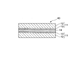
- the adhesive layer 14 was formed by applying using a Meyer bar and drying at 80 ° C. for 1 minute. Next, this adhesive layer 14 was laminated so that the vapor deposition layer 13 of the other gas barrier film 11 and the adhesive layer 14 were in contact with each other, and a solar cell module protective sheet 40 having the structure shown in FIG. 4 was obtained.
- Example 3 A Meyer bar is used so that the fluororesin coating liquid is formed on one of the vapor-deposited layers 13 in the protective sheet for a solar cell module having the structure shown in FIG. And then dried at 130 ° C. for 1 minute to form a fluororesin layer 15 to obtain a solar cell module protective sheet 20 having a structure shown in FIG.
- Example 4 On the vapor deposition layer 13 which is not provided with the fluororesin layer 15 in the protective sheet for the solar cell module having the structure shown in FIG. 2 which is manufactured in Example 3, the adhesive coating liquid is dried to have a thickness of 5 ⁇ m.
- the adhesive layer 17 was formed by applying using a Meyer bar and drying at 80 ° C. for 1 minute.
- an EVA film having a thickness of 100 ⁇ m is prepared as the thermal adhesive layer 16, laminated so that the adhesive layer 17 formed as described above and the EVA film having a thickness of 100 ⁇ m are in contact with each other, and the solar cell module having the structure shown in FIG. A sheet 30 was obtained.
- the protective sheets for solar cell modules of Examples 1 to 7 in which two or more gas barrier films 11 comprising the base film 12 and the vapor deposition layer 13 are laminated have a water vapor permeability of 1.0 ⁇ 10 ⁇ It was less than 1 g / m 2 ⁇ 24 h, and it was confirmed that the film has sufficient moisture resistance as a protective sheet for a solar cell module.
- the protective sheet for the solar cell module of the comparative example has a water vapor permeability of 3.3 ⁇ 10 ⁇ 1 g / m 2 ⁇ 24 h, and the moisture-proof property as the protective sheet for the solar cell module is insufficient. confirmed.
Landscapes
- Physics & Mathematics (AREA)
- Condensed Matter Physics & Semiconductors (AREA)
- Electromagnetism (AREA)
- General Physics & Mathematics (AREA)
- Engineering & Computer Science (AREA)
- Computer Hardware Design (AREA)
- Microelectronics & Electronic Packaging (AREA)
- Power Engineering (AREA)
- Photovoltaic Devices (AREA)
- Laminated Bodies (AREA)
Abstract
Description
本願は、2009年3月6日に、日本に出願された特願2009-054203号に基づき優先権を主張し、その内容をここに援用する。
図9は、太陽電池モジュールの一例を示す概略断面図である。
この太陽電池モジュール100は、結晶シリコンおよびアモルファスシリコンなどからなる太陽電池セル101と、太陽電池セル101を封止する電気絶縁体からなる封止材(充填層)102と、封止材102の表面に積層された表面保護シート(フロントシート)103と、封止材102の裏面に積層された裏面保護シート(バックシート)104とから概略構成されている。
以下、表面保護シート103と裏面保護シート104を総称して、「保護シート」と言うこともある。
(1)基材フィルムの少なくとも一方の面に無機酸化物からなる蒸着層が設けられてなるガスバリア性フィルムが2層以上積層された太陽電池モジュール用保護シートであって、前記太陽電池モジュール用保護シートを構成する材料が、発電に寄与する波長の光線を透過する材料からなり、前記太陽電池モジュール用保護シートがフロントシートとして用いられていることを特徴とする太陽電池モジュール用保護シート。
(2)JIS K7129に準拠して測定される水蒸気透過度が、1.0×10⁻¹g/m2・24h未満であることを特徴とする(1)に記載の太陽電池モジュール用保護シート。
(3)積層された前記ガスバリア性フィルムの少なくとも一方の外面に熱接着性層が設けられていることを特徴とする(1)に記載の太陽電池モジュール用保護シート。
(4)少なくとも一方の最外層にフッ素樹脂層が設けられていることを特徴とする(1)に記載の太陽電池モジュール用保護シート。
(5)前記フッ素樹脂層が、フッ素含有樹脂を有する塗料を塗布してなる塗膜から形成されている層であることを特徴とする(4)に記載の太陽電池モジュール用保護シート。
(6)基材フィルムの少なくとも一方の面に無機酸化物からなる蒸着層が設けられてなるガスバリア性フィルムが2層以上積層された太陽電池モジュール用保護シートであって、前記太陽電池モジュール用保護シートがバックシートとして用いられていることを特徴とする太陽電池モジュール用保護シート。
(7)JIS K7129に準拠して測定される水蒸気透過度が、1.0×10⁻¹g/m2・24h未満であることを特徴とする(6)に記載の太陽電池モジュール用保護シート。
(8)積層された前記ガスバリア性フィルムの少なくとも一方の外面に熱接着性層が設けられていることを特徴とする(6)に記載の太陽電池モジュール用保護シート。
(9)少なくとも一方の最外層にフッ素樹脂層が設けられていることを特徴とする(6)に記載の太陽電池モジュール用保護シート。
(10)前記フッ素樹脂層が、フッ素含有樹脂を有する塗料を塗布してなる塗膜から形成されている層であることを特徴とする(9)に記載の太陽電池モジュール用保護シート。
(11)前記太陽電池モジュール用保護シートを構成する層の少なくとも1層が、発電に寄与する波長の光線を反射する層からなることを特徴とする(6)に記載の太陽電池モジュール用保護シート。
(12)(1)ないし(5)のいずれか1項に記載の太陽電池モジュール用保護シートがフロントシートとして用いられ、(6)ないし(11)のいずれか1項に記載の太陽電池モジュール用保護シートがバックシートとして用いられ、かつ太陽電池モジュールを構成する太陽電池セルにフレキシブル基板が用いられていることを特徴とする太陽電池モジュール。
なお、この形態は、発明の趣旨をより良く理解させるために具体的に説明するものであり、特に指定のない限り、本発明を限定するものではない。
図1は、本発明の太陽電池モジュール用保護シートの第一の実施形態を示す概略断面図である。
この太陽電池モジュール用保護シート10は、上述した太陽電池モジュール100のフロントシート103またはバックシート104(図9参照)に適用されるものである。
この実施形態では、太陽電池モジュール用保護シートを、太陽電池モジュールのバックシートに適用した場合を例にして説明する。
以下、太陽電池モジュール用保護シート10を、バックシート10と言うこともある。
ガスバリア性フィルム11は、基材フィルム12と、基材フィルム12の一方の面12aに設けられた蒸着層13とから構成されている。2つのガスバリア性フィルム11は、それぞれ基材フィルム12における蒸着層13が設けられていない側の面(以下、「基材フィルム12の他方の面」と言う。)12bを相互に臨ませた状態で積層されている。
蒸着層13を形成する蒸着方法としては、例えば、プラズマ化学気相成長法、熱化学気相成長法および光化学気相成長法などの化学気相法、または、真空蒸着法、スパッタリング法およびイオンプレーティング法などの物理気相法が用いられる。これらの方法の中でも、操作性や層厚の制御性を考慮した場合、真空蒸着法が好ましい。
金属酸化物としては、例えば、ケイ素(Si)、アルミニウム(Al)、マグネシウム(Mg)、カルシウム(Ca)、カリウム(K)、スズ(Sn)、ナトウリム(Na)、ホウ素(B)、チタン(Ti)、鉛(Pb)、ジルコニウム(Zr)またはイットリウム(Y)などの金属の酸化物が用いられる。これらの金属酸化物の中でも、ケイ素(Si)の金属酸化物である二酸化ケイ素(SiO2)や、アルミニウム(Al)の金属酸化物である酸化アルミニウム(Al2O3)が好ましい。
蒸着層13が複数種の金属酸化物からなる場合、各金属酸化物からなる層が順に蒸着された積層構造の蒸着層であってもよく、複数種の金属酸化物が同時に蒸着された蒸着層であってもよい。
接着層14を構成する接着剤としては、ポリアクリル系接着剤、ポリウレタン系接着剤、エポキシ系接着剤、ポリエステル系接着剤またはポリエステルポリウレタン系接着剤などが用いられる。これらの接着剤は1種を単独で用いてもよく、2種以上を組み合わせて用いてもよい。これらの中でも、ポリエステルポリウレタン系接着剤が基材フィルム12との接着性に優れる点で特に好ましい。
接着層14の厚みは、1μm~20μmが好ましく、3μm~10μmがより好ましい。
また、この実施形態では、基材フィルム12の一方の面12aに蒸着層13が設けられたガスバリア性フィルム11を備えた太陽電池モジュール用保護シート(バックシート)10を例示したが、本発明の太陽電池モジュール用保護シートはこれに限定されない。本発明の太陽電池モジュール用保護シートにあっては、基材フィルムの両面(一方の面および他方の面)に蒸着層が設けられていてもよい。
図2は、本発明の太陽電池モジュール用保護シートの第二の実施形態を示す概略断面図である。
図2において、図1に示した太陽電池モジュール用保護シート10と同じ構成要素には同一の符号を付して説明を省略する。
この実施形態の太陽電池モジュール用保護シート20は、第一の実施形態と同様に、太陽電池モジュールのバックシートに適用することができる。
以下、太陽電池モジュール用保護シート20を、バックシート20と言うこともある。
この実施形態では、基材フィルム12、蒸着層13および接着層14の構成は、第一の実施形態におけるそれらの構成と同様である。
一方、フッ素樹脂層15がフッ素含有樹脂を有する塗料を塗布してなる塗膜から形成される層である場合、通常、接着層を介することなく、フッ素含有樹脂を含有した塗料を蒸着層13に直接塗布することにより、蒸着層13にフッ素樹脂層15が積層される。
PVFを主成分とする樹脂としては、例えば、「Tedlar(商品名、E.I.du Pont de Nemours and Company社製)」が挙げられる。
ECTFEを主成分とする樹脂としては、例えば、「Halar(商品名、Solvay Solexis社製)」が挙げられる。
ETFEを主成分とする樹脂としては、例えば、「Fluon(商品名、旭硝子社製)」が挙げられる。
塗料に含まれるフッ素含有樹脂としては、硬化性官能基を有するフルオロオレフィン樹脂が好ましい。このフルオロオレフィン樹脂としては、テトラフルオロエチレン(TFE)、イソブチレン、フッ化ビニリデン(VdF)、ヒドロキシブチルビニルエーテルおよびその他のモノマーからなる共重合体、ならびに、TFE、VdF、ヒドロキシブチルビニルエーテルおよびその他のモノマーからなる共重合体が挙げられる。
これらの中でも、耐候性および顔料分散性などの観点から、CTFEを主成分としたポリマー類およびTFEを主成分としたポリマー類が好ましく、「LUMIFLON」および「ZEFFLE」が最も好ましい。
「ZEFFLE」としては、TFEと有機溶媒可溶性の炭化水素オレフィンとの共重合体であり、なかでも反応性の高い水酸基を備えた炭化水素オレフィンを含む樹脂が、溶剤可溶性、架橋反応性、基材密着性および顔料分散性に優れるので好ましい。
三元重合体としては、例えば、VdFとTFEとヘキサフルオロプロピレンとの三元重合体である「Dyneon THV(商品名、3M Company社製)」が挙げられる。このような三元重合体は、それぞれのモノマーが有する特性を樹脂に付与することができるので好ましい。例えば、「Dyneon THV」を使用すると、比較的低温でフッ素樹脂層を製造することができ、エラストマーや炭化水素ベースのプラスチックにも接着でき、柔軟性や光学的透明度にも優れるので好ましい。
このような溶媒のなかでも、塗料中の含有成分の溶解性および塗膜中への残留性の低さ(低い沸点温度)の観点から、キシレン、シクロヘキサノンまたはMEKから選択されるいずれか1種または2種以上の有機溶媒を含む溶媒が好ましい。
架橋剤としては、本発明の効果を損なうものでなければ特に限定されず、金属キレート類、シラン類、イソシアネート類またはメラミン類が好適である。バックシート20を屋外において30年以上使用することを想定した場合、耐候性の観点から、架橋剤としては、脂肪族のイソシアネート類が好ましい。
この組成物の組成比は、塗料全体を100質量%としたとき、フッ素含有樹脂の含有率は3~80質量%が好ましく、25~50質量%がより好ましく、顔料の含有率は5~60質量%が好ましく、10~30質量%がより好ましく、溶媒の含有率は20~80質量%が好ましく、25~65質量%がより好ましい。
また、触媒としては、例えば、ジブチルジラウリン酸スズが挙げられ、この触媒はフッ素含有樹脂とイソシアネートとの架橋を促進するために用いられる。
蒸着層13に塗布した塗料の乾燥温度は、本発明の効果を損なわない温度であればよく、蒸着層13および基材フィルム12への影響を低減する観点からは、50~130℃の範囲であることが好ましい。
図3は、本発明の太陽電池モジュール用保護シートの第三の実施形態を示す概略断面図である。
図3において、図1に示した太陽電池モジュール用保護シート10、および、図2に示した太陽電池モジュール用保護シート20と同じ構成要素には同一の符号を付して説明を省略する。
この実施形態の太陽電池モジュール用保護シート30は、第一の実施形態および第二の実施形態と同様に、太陽電池モジュールのバックシートに適用することができる。
以下、太陽電池モジュール用保護シート30を、バックシート30と言うこともある。
この実施形態では、基材フィルム12、蒸着層13および接着層14の構成は、第一の実施形態におけるそれらの構成と同様であり、フッ素樹脂層15の構成は、第二の実施形態における構成と同様である。
一般に、太陽電池モジュールを構成する封止材としては、EVAからなる封止樹脂が多用されているが、熱接着性層16がEVAを主成分とするポリマーからなる樹脂であることにより、封止材と熱接着性層16との適合性および接着性を向上させることができる。
接着層17を構成する接着剤としては、本発明の効果を損なわないものであれば特に制限されず、ポリアクリル系接着剤、ポリウレタン系接着剤、エポキシ系接着剤、ポリエステル系接着剤またはポリエステルポリウレタン系接着剤などが挙げられる。これらの接着剤は1種を単独で用いてもよく、2種以上を組み合わせて用いてもよい。これらの中でも、ポリエステルポリウレタン系接着剤が熱接着性層16および蒸着層13との接着性に優れる点で特に好ましい。
接着層17の厚みは、1μm~20μmが好ましく、3μm~10μmがより好ましい。
発電に寄与する波長の光線を反射する層は、例えば基材フィルム12、接着層14、フッ素樹脂層15、熱接着性層16および後述する外面層18等の太陽電池モジュール用保護シートを構成する層の少なくとも1層を形成する材料に光反射材料を混合することで得ることができる。また、アルミ等の金属蒸着層を例えば基材フィルム12上に形成することで得ることができる。
上記光反射材料としては、特に限定されないが、通常、白色顔料が用いられる。白色顔料としては、二酸化チタン、酸化亜鉛、酸化アルミニウム、硫酸カルシウム、硫酸バリウムおよび炭酸カルシウム等が挙げられる。これらは、1種単独で、あるいは2種以上を組み合わせて用いることができる。
バックシートとして用いられる太陽電池モジュール用保護シートの太陽電池セルに対向する面の光線反射率としては、波長400~1100nmの範囲における反射率の最大値が50%以上であることが好ましい。
外面層18においては、基材フィルム12と同様のフィルムを使用できる。
中間層19においては、基材フィルム12と同様のフィルムを使用できる。
本発明の第四の実施形態は、上記の第一~第三の実施形態から選択される太陽電池モジュール用保護シートを、フロントシートまたはバックシートのいずれか一方として設けた太陽電池モジュールである。第一~第三の実施形態の太陽電池モジュール用保護シートを、太陽電池モジュールのフロントシートまたはバックシートのいずれか一方に適用した太陽電池モジュールとすることにより、上記の効果を奏する太陽電池モジュールが得られる。
本発明の第五の実施形態は、上記の第一~第三の実施形態から選択される太陽電池モジュール用保護シートを、フロントシートおよびバックシートの両方として設けた太陽電池モジュールである。第一~第三の実施形態の太陽電池モジュール用保護シートを、太陽電池モジュールのフロントシートおよびバックシートの両方に適用した太陽電池モジュールとすることにより、防湿性および耐衝撃性が高い太陽電池モジュールを得ることができる。さらに、太陽電池モジュールを構成する太陽電池セルにフレキシブル基板を用い、上記の第一~第三の実施形態の太陽電池モジュール用保護シートをフロントシートおよびバックシートの両方として設けることにより、フレキシブル性を有する太陽電池モジュールを得ることができる。このように、太陽電池モジュールをフレキシブル化することにより、ロールツウロールで大量生産することが可能となる。また、フレキシブル性を有する太陽電池モジュールは、アーチ状や放物線状の壁面を有する物体にもフィットさせることができるので、ドーム状の建築物や高速道路の防音壁などに設置することが可能となる。
基材フィルム12として、厚み12μmのPETフィルムを用い、このPETフィルムの片面に、スパッタリング法により、金属酸化物の二酸化ケイ素(SiO2)を厚み50nmとなるように成膜して、二酸化ケイ素からなる蒸着層13を形成した。
二酸化ケイ素の蒸着は、以下の条件で行った。
プラズマ生成ガス:アルゴン、酸素
ターゲット材料:ケイ素
ガス流量:アルゴン100scm、酸素50scm
電力値:DC2500W
チャンバー内圧:0.2Pa
二液硬化型ポリエステルポリウレタン系接着剤の主剤(三井化学ポリウレタン社製、商品名「タケラックA-515」)90質量部と、硬化剤(三井化学ポリウレタン社製、商品名「タケネートA-3」)10質量部とを混合し、接着層14および17に用いられる接着剤塗工液を調製した。
フッ素樹脂溶液(旭硝子社製、商品名「ルミフロンLF-200」、固形分:60質量%)100質量部と、イソシアネート系硬化剤(住化バイエルウレタン社製、商品名「スミジュール3300」、固形分:100質量%)10質量部と、二酸化チタン微粒子(E.I.du Pont de Nemours and Company社製、商品名「Ti-Pure R105」)30質量部とを混合し、フッ素樹脂層15に用いられるフッ素樹脂塗工液を調製した。
EVAを厚み100μmに調整して、熱接着性層16を形成した。
まず、上記のようにして作製したガスバリア性フィルム11を2枚用意し、一方のガスバリア性フィルム11の基材フィルム12面上に、接着剤塗工液を、乾燥後の厚みが5μmとなるように、マイヤーバーを用いて塗布し、80℃にて1分間乾燥して接着層14を形成した。
次いで、この接着層14に、他方のガスバリア性フィルム11の基材フィルム12と接着層14とが接するようにラミネートし、図1に示す構造の太陽電池モジュール用保護シート10を得た。
まず、上記のようにして作製したガスバリア性フィルム11を2枚用意し、一方のガスバリア性フィルム11の蒸着層13面上に、接着剤塗工液を、乾燥後の厚みが5μmとなるように、マイヤーバーを用いて塗布し、80℃にて1分間乾燥して接着層14を形成した。
次いで、この接着層14に、他方のガスバリア性フィルム11の蒸着層13と接着層14とが接するようにラミネートし、図4に示す構造の太陽電池モジュール用保護シート40を得た。
実施例1で作製した、図1に示す構造の太陽電池モジュール用保護シートにおける一方の蒸着層13上に、フッ素樹脂塗工液を、乾燥後の厚みが15μmとなるように、マイヤーバーを用いて塗布し、130℃にて1分間乾燥してフッ素樹脂層15を形成し、図2に示す構造の太陽電池モジュール用保護シート20を得た。
実施例3で作製した、図2に示す構造の太陽電池モジュール用保護シートにおけるフッ素樹脂層15を設けなかった蒸着層13上に、接着剤塗工液を、乾燥後の厚みが5μmとなるように、マイヤーバーを用いて塗布し、80℃にて1分間乾燥して接着層17を形成した。
次いで、熱接着層16として厚み100μmのEVAフィルムを用意し、上記のように形成した接着層17と厚み100μmのEVAフィルムとが接するようにラミネートし、図3に示す構造の太陽電池モジュール用保護シート30を得た。
実施例1で作製した、図1に示す構造の太陽電池モジュール用保護シートにおける一方の蒸着層13上に、接着剤塗工液を、乾燥後の厚みが5μmとなるように、マイヤーバーを用いて塗布し、80℃にて1分間乾燥して接着層14を形成した。
次いで、外面層18として、厚み125μmのPETフィルムを用意し、一方の蒸着層13上に形成した接着層14と、厚み125μmのPETフィルムとが接するようにラミネートした。
次いで、他方の蒸着層13上に、接着剤塗工液を、乾燥後の厚みが5μmとなるように、マイヤーバーを用いて塗布し、80℃にて1分間乾燥して接着層14を形成した。
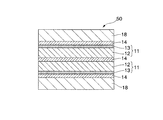
次いで、外面層18として、厚み125μmのPETフィルムを用意し、他方の蒸着層13上に形成した接着層14と、厚み125μmのPETフィルムとが接するようにラミネートし、図5に示す構造の太陽電池モジュール用保護シート50を得た。
この実施例では、実施例1で作製した図1に示す構造の太陽電池モジュール用保護シートを上下から挟むように、外面層18が設けられている。
まず、上記のように作製したガスバリア性フィルム11を2枚用意し、一方のガスバリア性フィルム11の蒸着層13面上に、接着剤塗工液を、乾燥後の厚みが5μmとなるように、マイヤーバーを用いて塗布し、80℃にて1分間乾燥して接着層14を形成した。
次いで、この接着層14に、他方のガスバリア性フィルム11の基材フィルム12と接着層14とが接するようにラミネートした。
次いで、上記の一方のガスバリア性フィルム11の基材フィルム12上に、接着剤塗工液を、乾燥後の厚みが5μmとなるように、マイヤーバーを用いて塗布し、80℃にて1分間乾燥し、接着層17を形成した。
次いで、熱接着性層16として厚み100μmのEVAフィルムを用意し、上記のように形成した接着層17と厚み100μmのEVAフィルムとが接するようにラミネートした。
次いで、上記の他方のガスバリア性フィルム11の蒸着層13面上に、接着剤塗工液を、乾燥後の厚みが5μmとなるように、マイヤーバーを用いて塗布し、80℃にて1分間乾燥して接着層14を形成した。
次いで、中間層19として厚み125μmのPETフィルムを用意し、上記のように形成した接着層14と厚み125μmのPETフィルムとが接するようにラミネートした。
次いで、上記の中間層19上に、フッ素樹脂塗工液を、乾燥後の厚みが15μmとなるように、マイヤーバーを用いて塗布し、130℃にて1分間乾燥してフッ素樹脂層15を形成し、図6に示す構造の太陽電池モジュール用保護シート60を得た。
実施例1で作製した、図1に示す構造の太陽電池モジュール用保護シートにおける一方の蒸着層13上に、接着剤塗工液を、乾燥後の厚みが5μmとなるように、マイヤーバーを用いて塗布し、80℃にて1分間乾燥して接着層14を形成した。
次いで、第3のガスバリア性フィルム11を用意し、一方の蒸着層13上に形成した接着層14と第3のガスバリア性フィルム11の基材フィルム12とが接するようにラミネートし、図7に示す構造の太陽電池モジュール用保護シート70を得た。
上記のように作製したガスバリア性フィルム11をそのまま用い、図8に示す構造の太陽電池モジュール用保護シートを得た。
以上の実施例1~7および比較例の太陽電池モジュール用保護シートについて、日本工業規格JIS K7129に準拠して水蒸気透過度を測定し、水蒸気透過性を評価した。
具体的には、各太陽電池モジュール用保護シートを水蒸気透過度測定装置(MOCON社製、装置名「AQUATRAN」、水蒸気透過度の検出下限値:0.0005g/m2・24h)を用いて、温度40℃、湿度90%RHの条件で水蒸気透過度を測定した。
結果を表1に示す。

一方、比較例の太陽電池モジュール用保護シートは、水蒸気透過度が3.3×10⁻¹g/m2・24hであり、太陽電池モジュール用保護シートとしての防湿性が不十分であることが確認された。
まず、実施例5で作製した、図5に示す構造の太陽電池モジュール用保護シートにおける一方の外面層18上に、接着剤塗工液を、乾燥後の厚みが5μmとなるように、マイヤーバーを用いて塗布し、80℃にて1分間乾燥して接着層を形成した。
次いで、熱接着性層として厚み100μmのEVAフィルムを用意し、上記のように形成した接着層と厚み100μmのEVAフィルムとが接するようにラミネートし、フロントシートを得た。
一方、実施例4で作製した、図3に示す構造の太陽電池モジュール用保護シート30と、太陽電池用フレキシブル基板(ガラス繊維強化プラスチックフィルムにアモルファス太陽電池を貼り付けたもの)とを用意した。太陽電池モジュール用保護シート30の熱接着性層16がフレキシブル基板に接するようにフレキシブル基板を重ね、太陽電池モジュール用保護シート30をバックシートとした。
次いで、そのフレキシブル基板上に、上記のフロントシートの熱接着性層がフレキシブル基板に接するように重ねた後、全体を加熱ロールで熱圧着して、フロントシート/フレキシブル基板/バックシートの構成からなる太陽電池モジュールを作製した。
上記のようにして得られた太陽電池モジュールは、フレキシブル性を有しており、放物線状の壁面を有する物体にもフィットさせることができた。
11 ガスバリア性フィルム
12 基材フィルム
13 蒸着層
14 接着層
15 フッ素樹脂層
16 熱接着性層
17 接着層
18 外面層
19 中間層
Claims (12)
- 基材フィルムの少なくとも一方の面に無機酸化物からなる蒸着層が設けられてなるガスバリア性フィルムが2層以上積層された太陽電池モジュール用保護シートであって、
前記太陽電池モジュール用保護シートを構成する材料が、発電に寄与する波長の光線を透過する材料からなり、
前記太陽電池モジュール用保護シートがフロントシートとして用いられていることを特徴とする太陽電池モジュール用保護シート。 - JIS K7129に準拠して測定される水蒸気透過度が、1.0×10⁻¹g/m2・24h未満であることを特徴とする請求項1に記載の太陽電池モジュール用保護シート。
- 積層された前記ガスバリア性フィルムの少なくとも一方の外面に熱接着性層が設けられていることを特徴とする請求項1に記載の太陽電池モジュール用保護シート。
- 少なくとも一方の最外層にフッ素樹脂層が設けられていることを特徴とする請求項1に記載の太陽電池モジュール用保護シート。
- 前記フッ素樹脂層が、フッ素含有樹脂を有する塗料を塗布してなる塗膜から形成されている層であることを特徴とする請求項4に記載の太陽電池モジュール用保護シート。
- 基材フィルムの少なくとも一方の面に無機酸化物からなる蒸着層が設けられてなるガスバリア性フィルムが2層以上積層された太陽電池モジュール用保護シートであって、
前記太陽電池モジュール用保護シートがバックシートとして用いられていることを特徴とする太陽電池モジュール用保護シート。 - JIS K7129に準拠して測定される水蒸気透過度が、1.0×10⁻¹g/m2・24h未満であることを特徴とする請求項6に記載の太陽電池モジュール用保護シート。
- 積層された前記ガスバリア性フィルムの少なくとも一方の外面に熱接着性層が設けられていることを特徴とする請求項6に記載の太陽電池モジュール用保護シート。
- 少なくとも一方の最外層にフッ素樹脂層が設けられていることを特徴とする請求項6に記載の太陽電池モジュール用保護シート。
- 前記フッ素樹脂層が、フッ素含有樹脂を有する塗料を塗布してなる塗膜から形成されている層であることを特徴とする請求項9に記載の太陽電池モジュール用保護シート。
- 前記太陽電池モジュール用保護シートを構成する層の少なくとも1層が、発電に寄与する波長の光線を反射する層からなることを特徴とする請求項6に記載の太陽電池モジュール用保護シート。
- 請求項1ないし5のいずれか1項に記載の太陽電池モジュール用保護シートがフロントシートとして用いられ、
請求項6ないし11のいずれか1項に記載の太陽電池モジュール用保護シートがバックシートとして用いられ、かつ
太陽電池モジュールを構成する太陽電池セルにフレキシブル基板が用いられていることを特徴とする太陽電池モジュール。
Priority Applications (4)
| Application Number | Priority Date | Filing Date | Title |
|---|---|---|---|
| US13/255,017 US20120006401A1 (en) | 2009-03-06 | 2010-03-05 | Protective sheet for solar cell module, and solar cell module using same |
| EP10748542A EP2405484A1 (en) | 2009-03-06 | 2010-03-05 | Protective sheet for solar cell module, and solar cell module using same |
| CN2010800109112A CN102341918A (zh) | 2009-03-06 | 2010-03-05 | 太阳能电池组件用保护片以及使用该保护片的太阳能电池组件 |
| JP2011502666A JPWO2010100943A1 (ja) | 2009-03-06 | 2010-03-05 | 太陽電池モジュール用保護シートおよびこれを用いた太陽電池モジュール |
Applications Claiming Priority (2)
| Application Number | Priority Date | Filing Date | Title |
|---|---|---|---|
| JP2009-054203 | 2009-03-06 | ||
| JP2009054203 | 2009-03-06 |
Publications (1)
| Publication Number | Publication Date |
|---|---|
| WO2010100943A1 true WO2010100943A1 (ja) | 2010-09-10 |
Family
ID=42709509
Family Applications (1)
| Application Number | Title | Priority Date | Filing Date |
|---|---|---|---|
| PCT/JP2010/001547 WO2010100943A1 (ja) | 2009-03-06 | 2010-03-05 | 太陽電池モジュール用保護シートおよびこれを用いた太陽電池モジュール |
Country Status (5)
| Country | Link |
|---|---|
| US (1) | US20120006401A1 (ja) |
| EP (1) | EP2405484A1 (ja) |
| JP (1) | JPWO2010100943A1 (ja) |
| CN (1) | CN102341918A (ja) |
| WO (1) | WO2010100943A1 (ja) |
Cited By (9)
| Publication number | Priority date | Publication date | Assignee | Title |
|---|---|---|---|---|
| US20120160315A1 (en) * | 2010-12-22 | 2012-06-28 | Lg Electronics Inc. | Thin film solar cell module and manufacturing method thereof |
| WO2013019763A1 (en) | 2011-08-04 | 2013-02-07 | 3M Innovative Properties Company | Edge protected barrier assemblies |
| CN103619584A (zh) * | 2011-05-16 | 2014-03-05 | Lg化学株式会社 | 用于太阳能电池的保护膜及包含该保护膜的太阳能电池 |
| CN103857760A (zh) * | 2011-08-03 | 2014-06-11 | 琳得科株式会社 | 阻气性粘合片材、其制造方法、以及电子构件及光学构件 |
| JP2015185595A (ja) * | 2014-03-20 | 2015-10-22 | 凸版印刷株式会社 | 太陽電池モジュール |
| JP2015208960A (ja) * | 2014-04-28 | 2015-11-24 | 凸版印刷株式会社 | ガスバリア性積層フィルム及び有機elデバイス |
| US9412960B2 (en) | 2011-04-18 | 2016-08-09 | The Regents Of The University Of Michigan | Light trapping architecture for photovoltaic and photodector applications |
| JP2019504494A (ja) * | 2015-12-23 | 2019-02-14 | アムコア フレキシブル トランスパック エヌ.ブィ. | 熱反射ソーラーモジュール |
| JP2019140273A (ja) * | 2018-02-13 | 2019-08-22 | 大日本印刷株式会社 | 太陽電池モジュール |
Families Citing this family (14)
| Publication number | Priority date | Publication date | Assignee | Title |
|---|---|---|---|---|
| US9735298B2 (en) * | 2007-02-16 | 2017-08-15 | Madico, Inc. | Backing sheet for photovoltaic modules |
| US8507029B2 (en) * | 2007-02-16 | 2013-08-13 | Madico, Inc. | Backing sheet for photovoltaic modules |
| US20080264484A1 (en) * | 2007-02-16 | 2008-10-30 | Marina Temchenko | Backing sheet for photovoltaic modules and method for repairing same |
| US20100288333A1 (en) * | 2009-05-14 | 2010-11-18 | Marina Temchenko | Heat dissipating protective sheets and encapsulant for photovoltaic modules |
| US20100294363A1 (en) * | 2009-05-22 | 2010-11-25 | Mitsubishi Polyester Film, Inc. | Coated Polyester Film For Lamination to Ethylene-Vinyl Acetate Layers |
| CN102687278A (zh) * | 2009-12-23 | 2012-09-19 | 马迪可公司 | 用于光伏应用的高性能背板及其制备方法 |
| EP2718980A1 (de) * | 2011-06-07 | 2014-04-16 | Saint-Gobain Glass France | Solarmodul |
| KR101911581B1 (ko) | 2011-08-04 | 2018-10-24 | 쓰리엠 이노베이티브 프로퍼티즈 컴파니 | 에지 보호된 배리어 조립체 |
| DE102011113160A1 (de) * | 2011-09-14 | 2013-03-14 | Evonik Röhm Gmbh | Polymere Materialien für Außenanwendungen mit selbstheilenden Oberflächeneigenschaften nach Verkratzen oder Abrasionsbeschädigung |
| TW201349515A (zh) * | 2012-05-16 | 2013-12-01 | Saint Gobain Performance Plast | 光伏打背板 |
| HRPK20120648B3 (hr) * | 2012-08-08 | 2015-05-08 | Icat D.O.O. | Solarne ä†elije integrirane u stakloplastiäśnu ljusku oplošja plovila |
| KR101350424B1 (ko) * | 2013-04-26 | 2014-01-16 | 에스지글로벌 주식회사 | 접착부재 및 이를 구비한 터치스크린용 디스플레이 유닛 |
| US20190280136A1 (en) * | 2017-02-16 | 2019-09-12 | Panasonic Intellectual Property Management Co., Ltd. | Solar cell module |
| CN108766865A (zh) * | 2018-05-21 | 2018-11-06 | 北京铂阳顶荣光伏科技有限公司 | 一种柔性太阳能电池前板的制备方法 |
Citations (7)
| Publication number | Priority date | Publication date | Assignee | Title |
|---|---|---|---|---|
| JPH0476231A (ja) | 1990-07-13 | 1992-03-11 | Honda Motor Co Ltd | ガスタービンエンジン |
| JP2000294820A (ja) | 1999-04-07 | 2000-10-20 | Bridgestone Corp | 太陽電池用バックカバー材及び太陽電池 |
| JP2006261287A (ja) * | 2005-03-16 | 2006-09-28 | Teijin Dupont Films Japan Ltd | 太陽電池用表面保護フィルムおよびそれを用いた太陽電池積層体 |
| JP2007129015A (ja) * | 2005-11-02 | 2007-05-24 | Dainippon Printing Co Ltd | 太陽電池モジュールおよび太陽電池モジュール用裏面保護シート |
| JP2008028294A (ja) * | 2006-07-25 | 2008-02-07 | Toppan Printing Co Ltd | 太陽電池裏面封止用シート |
| JP2009010269A (ja) * | 2007-06-29 | 2009-01-15 | Toppan Printing Co Ltd | 太陽電池モジュール用裏面保護シートおよびそれを用いた太陽電池モジュール |
| JP2009054203A (ja) | 2007-08-23 | 2009-03-12 | Toshiba Corp | 記録装置および記録方法 |
Family Cites Families (8)
| Publication number | Priority date | Publication date | Assignee | Title |
|---|---|---|---|---|
| CN1112734C (zh) * | 1993-09-30 | 2003-06-25 | 佳能株式会社 | 具有三层结构表面覆盖材料的太阳能电池组件 |
| US6335479B1 (en) * | 1998-10-13 | 2002-01-01 | Dai Nippon Printing Co., Ltd. | Protective sheet for solar battery module, method of fabricating the same and solar battery module |
| JP2003031829A (ja) * | 2001-05-09 | 2003-01-31 | Canon Inc | 光起電力素子 |
| US7553540B2 (en) * | 2005-12-30 | 2009-06-30 | E. I. Du Pont De Nemours And Company | Fluoropolymer coated films useful for photovoltaic modules |
| CN101177514B (zh) * | 2007-11-08 | 2010-06-09 | 中国乐凯胶片集团公司 | 一种太阳能电池背板及其制备方法 |
| CN101290950B (zh) * | 2008-05-23 | 2011-02-02 | 浙江工业大学 | 一种太阳能电池板背膜及其生产工艺 |
| CN101359695A (zh) * | 2008-09-02 | 2009-02-04 | 中国乐凯胶片集团公司 | 一种太阳能电池背板 |
| CN101350370B (zh) * | 2008-09-18 | 2010-09-22 | 杭州福斯特光伏材料股份有限公司 | 一种用于太阳能电池组件的背板材料 |
-
2010
- 2010-03-05 EP EP10748542A patent/EP2405484A1/en not_active Withdrawn
- 2010-03-05 WO PCT/JP2010/001547 patent/WO2010100943A1/ja active Application Filing
- 2010-03-05 JP JP2011502666A patent/JPWO2010100943A1/ja active Pending
- 2010-03-05 CN CN2010800109112A patent/CN102341918A/zh active Pending
- 2010-03-05 US US13/255,017 patent/US20120006401A1/en not_active Abandoned
Patent Citations (7)
| Publication number | Priority date | Publication date | Assignee | Title |
|---|---|---|---|---|
| JPH0476231A (ja) | 1990-07-13 | 1992-03-11 | Honda Motor Co Ltd | ガスタービンエンジン |
| JP2000294820A (ja) | 1999-04-07 | 2000-10-20 | Bridgestone Corp | 太陽電池用バックカバー材及び太陽電池 |
| JP2006261287A (ja) * | 2005-03-16 | 2006-09-28 | Teijin Dupont Films Japan Ltd | 太陽電池用表面保護フィルムおよびそれを用いた太陽電池積層体 |
| JP2007129015A (ja) * | 2005-11-02 | 2007-05-24 | Dainippon Printing Co Ltd | 太陽電池モジュールおよび太陽電池モジュール用裏面保護シート |
| JP2008028294A (ja) * | 2006-07-25 | 2008-02-07 | Toppan Printing Co Ltd | 太陽電池裏面封止用シート |
| JP2009010269A (ja) * | 2007-06-29 | 2009-01-15 | Toppan Printing Co Ltd | 太陽電池モジュール用裏面保護シートおよびそれを用いた太陽電池モジュール |
| JP2009054203A (ja) | 2007-08-23 | 2009-03-12 | Toshiba Corp | 記録装置および記録方法 |
Cited By (13)
| Publication number | Priority date | Publication date | Assignee | Title |
|---|---|---|---|---|
| US20120160315A1 (en) * | 2010-12-22 | 2012-06-28 | Lg Electronics Inc. | Thin film solar cell module and manufacturing method thereof |
| US9412960B2 (en) | 2011-04-18 | 2016-08-09 | The Regents Of The University Of Michigan | Light trapping architecture for photovoltaic and photodector applications |
| CN103619584A (zh) * | 2011-05-16 | 2014-03-05 | Lg化学株式会社 | 用于太阳能电池的保护膜及包含该保护膜的太阳能电池 |
| CN103857760B (zh) * | 2011-08-03 | 2016-09-21 | 琳得科株式会社 | 阻气性粘合片材、其制造方法、以及电子构件及光学构件 |
| CN103857760A (zh) * | 2011-08-03 | 2014-06-11 | 琳得科株式会社 | 阻气性粘合片材、其制造方法、以及电子构件及光学构件 |
| CN103733726A (zh) * | 2011-08-04 | 2014-04-16 | 3M创新有限公司 | 边缘受保护的阻隔组件 |
| EP2740326A4 (en) * | 2011-08-04 | 2015-05-20 | 3M Innovative Properties Co | LOCKING DEVICE WITH EDGE PROTECTION |
| JP2014526150A (ja) * | 2011-08-04 | 2014-10-02 | スリーエム イノベイティブ プロパティズ カンパニー | エッジの保護されたバリアー性組立品 |
| WO2013019763A1 (en) | 2011-08-04 | 2013-02-07 | 3M Innovative Properties Company | Edge protected barrier assemblies |
| JP2015185595A (ja) * | 2014-03-20 | 2015-10-22 | 凸版印刷株式会社 | 太陽電池モジュール |
| JP2015208960A (ja) * | 2014-04-28 | 2015-11-24 | 凸版印刷株式会社 | ガスバリア性積層フィルム及び有機elデバイス |
| JP2019504494A (ja) * | 2015-12-23 | 2019-02-14 | アムコア フレキシブル トランスパック エヌ.ブィ. | 熱反射ソーラーモジュール |
| JP2019140273A (ja) * | 2018-02-13 | 2019-08-22 | 大日本印刷株式会社 | 太陽電池モジュール |
Also Published As
| Publication number | Publication date |
|---|---|
| JPWO2010100943A1 (ja) | 2012-09-06 |
| CN102341918A (zh) | 2012-02-01 |
| EP2405484A1 (en) | 2012-01-11 |
| US20120006401A1 (en) | 2012-01-12 |
Similar Documents
| Publication | Publication Date | Title |
|---|---|---|
| WO2010100943A1 (ja) | 太陽電池モジュール用保護シートおよびこれを用いた太陽電池モジュール | |
| WO2010116650A1 (ja) | 太陽電池モジュール用保護シートおよびその製造方法、並びに、太陽電池モジュール | |
| WO2010109896A1 (ja) | 太陽電池モジュール用保護シートおよびこれを備えた太陽電池モジュール | |
| TWI480157B (zh) | 太陽能電池模組用背面保護片及其製造方法、與太陽能電池模組 | |
| WO2010073735A1 (ja) | 太陽電池モジュール用裏面保護シート | |
| KR101796140B1 (ko) | 태양전지용 보호시트 및 그 제조 방법, 및 태양전지 모듈 | |
| JP5714959B2 (ja) | 太陽電池用保護シートおよびその製造方法、ならびに太陽電池モジュール | |
| EP2247391A1 (en) | Backing sheet for photovoltaic modules | |
| WO2012132922A1 (ja) | 太陽電池用保護シートおよびその製造方法、ならびに太陽電池モジュール | |
| JP2011124428A (ja) | 太陽電池モジュール用保護シート及び太陽電池モジュール | |
| JP2010232513A (ja) | 太陽電池モジュール用裏面保護シート及び太陽電池モジュール | |
| JP2011181671A (ja) | 太陽電池モジュール用保護シートおよび太陽電池モジュール | |
| JP2010219196A (ja) | 太陽電池モジュール用裏面保護シート及び太陽電池モジュール | |
| JP2010232233A (ja) | 太陽電池モジュール用保護シートおよびその製造方法、並びに、太陽電池モジュール | |
| JP5484762B2 (ja) | 太陽電池モジュール用保護シートの製造方法 | |
| WO2010116635A1 (ja) | 太陽電池モジュール用保護シートおよびそれを備える太陽電池モジュール | |
| JP5335496B2 (ja) | 太陽電池モジュール用保護シート | |
| JP2010232441A (ja) | 太陽電池モジュール用保護シート及び太陽電池モジュール | |
| JP2011204880A (ja) | 太陽電池モジュール用保護シート及び太陽電池モジュール | |
| JP2010232294A (ja) | 太陽電池モジュール用保護シート及び太陽電池モジュール | |
| JP2012015264A (ja) | 太陽電池モジュール用保護シート及び太陽電池モジュール | |
| JP2012089632A (ja) | 太陽電池用保護シートおよびその製造方法、ならびに太陽電池モジュール | |
| TWI546976B (zh) | A protective sheet for a solar cell and a method for manufacturing the same, and a solar cell module | |
| JP2012089631A (ja) | 太陽電池用保護シートおよびその製造方法、ならびに太陽電池モジュール |
Legal Events
| Date | Code | Title | Description |
|---|---|---|---|
| WWE | Wipo information: entry into national phase |
Ref document number: 201080010911.2 Country of ref document: CN |
|
| 121 | Ep: the epo has been informed by wipo that ep was designated in this application |
Ref document number: 10748542 Country of ref document: EP Kind code of ref document: A1 |
|
| WWE | Wipo information: entry into national phase |
Ref document number: 2011502666 Country of ref document: JP |
|
| NENP | Non-entry into the national phase |
Ref country code: DE |
|
| WWE | Wipo information: entry into national phase |
Ref document number: 13255017 Country of ref document: US |
|
| WWE | Wipo information: entry into national phase |
Ref document number: 2010748542 Country of ref document: EP |