WO2010092958A1 - 質量分析技術を用いた免疫分析方法および免疫分析システム - Google Patents
質量分析技術を用いた免疫分析方法および免疫分析システム Download PDFInfo
- Publication number
- WO2010092958A1 WO2010092958A1 PCT/JP2010/051904 JP2010051904W WO2010092958A1 WO 2010092958 A1 WO2010092958 A1 WO 2010092958A1 JP 2010051904 W JP2010051904 W JP 2010051904W WO 2010092958 A1 WO2010092958 A1 WO 2010092958A1
- Authority
- WO
- WIPO (PCT)
- Prior art keywords
- immunoassay
- measurement object
- mass spectrometry
- antigen
- antibody
- Prior art date
- Legal status (The legal status is an assumption and is not a legal conclusion. Google has not performed a legal analysis and makes no representation as to the accuracy of the status listed.)
- Ceased
Links
Images









Classifications
-
- G—PHYSICS
- G01—MEASURING; TESTING
- G01N—INVESTIGATING OR ANALYSING MATERIALS BY DETERMINING THEIR CHEMICAL OR PHYSICAL PROPERTIES
- G01N33/00—Investigating or analysing materials by specific methods not covered by groups G01N1/00 - G01N31/00
- G01N33/48—Biological material, e.g. blood, urine; Haemocytometers
- G01N33/50—Chemical analysis of biological material, e.g. blood, urine; Testing involving biospecific ligand binding methods; Immunological testing
- G01N33/68—Chemical analysis of biological material, e.g. blood, urine; Testing involving biospecific ligand binding methods; Immunological testing involving proteins, peptides or amino acids
- G01N33/6803—General methods of protein analysis not limited to specific proteins or families of proteins
- G01N33/6848—Methods of protein analysis involving mass spectrometry
Definitions
- the present invention relates to an immunoassay method and an immunoassay system used for clinical examination.
- immunization an antibody that specifically recognizes a measurement target component is applied. For example, after a measurement target component in a specimen is captured with an antibody (primary antibody), a secondary antibody that further selectively captures the primary antibody is obtained. Use to detect. For detection at this time, a label is added to the secondary antibody in order to increase sensitivity.
- the label may be, for example, a fluorescent substance or a substance necessary for enzyme chemiluminescence.
- the immunization method is a measurement technique that enables simple and sensitive detection, and is therefore suitable for quantitative measurement of trace components in a specimen.
- the cross-reactivity is a phenomenon in which not only a measurement target component that should be originally recognized by the primary antibody but also a molecule having a similar structure such as a metabolite of the measurement target component. This means that the quantitative result is higher than the true value, and the measurement target component cannot be accurately quantified.
- mass spectrometry is a measurement technique that can be distinguished from similar structural molecules such as metabolites because measurement is performed based on the mass of the component to be measured.
- MS / MS analysis and MSn analysis techniques are techniques that enable high-precision identification of similar structural components by fragment ionizing a measurement target component.
- mass spectrometry does not require preparation of a special reagent such as an antibody, cost and labor can be reduced.
- JP 2006-126033 A JP 2005-524394 A JP 2005-098830 A JP 2005-291823 A WO 2004-031759
- the most desirable is a component to be measured labeled with a stable isotope, but its synthesis is not only costly, but there is a problem that a stable isotope labeled product cannot be produced for a component that cannot be synthesized.
- An object of the present invention is to realize an immunoassay method and an immunoassay system that can eliminate the cross-reactivity of an immunization method and solve the problem of component determination of mass spectrometry.
- the present invention is configured as follows to achieve the above object.
- the measurement target in the sample solution is captured using an antibody by pretreatment by the immunoassay, the measurement target component is recovered from the captured measurement target, and the recovered measurement target component Is subjected to mass spectrometry by mass spectrometry, and the components of the measurement object are analyzed.
- the measurement object in the sample solution is captured using an antibody by pretreatment by the immunoassay method, the captured measurement object is quantified, and the measurement object is quantified.
- the measurement object is collected from the waste liquid that has been subjected to, the collected measurement object is subjected to mass spectrometry by mass spectrometry, and the components of the measurement object performed by the immunization method are measured.
- FIG. 1 It is a schematic block diagram of the whole sample immunity analysis system in Example 1 of this invention, and is a figure for showing the flow of a measurement. It is explanatory drawing of the immunity law. It is explanatory drawing of the waste liquid process of the immunity law. It is a figure which shows the cross-reactivity and drug efficacy of tacrolimus. It is a figure which shows the data regarding the measuring object in a patient sample. It is a figure which shows the apparatus structural example of the sample immunity analysis system shown in FIG. It is a figure which shows the other apparatus structural example of the sample immunity analysis system shown in FIG. It is a figure which shows the further another apparatus structural example of the sample immunity analysis system shown in FIG.
- FIG. It is a figure which shows the further another apparatus structural example of the sample immunity analysis system shown in FIG. It is a schematic block diagram of the whole sample immunity analysis system in Example 2 of this invention, and is a figure for showing the flow of a measurement. It is explanatory drawing of the application in the pretreatment for immunization methods. It is explanatory drawing of measurement object component collection
- Example 1 of the present invention will be described with respect to an example in which a component of a waste liquid after photometric measurement by immunization is detected by mass spectrometry.
- FIG. 1 is a schematic configuration diagram of the entire license analysis system 102 according to the first embodiment, and is a diagram for illustrating a flow of measurement.
- a sample 101 such as patient serum is subjected to pretreatment by an immunological pretreatment apparatus 103 and then photometrically measured by an immunological photometric detection system 104. Subsequently, pretreatment is performed by the mass spectrometry pretreatment device 105, and mass spectrometry is performed by the mass spectrometry detection system 106.
- These sample immunity analysis system 102, immunization pretreatment device 103, immunization photometric detection system 104, mass spectrometry pretreatment device 105, and mass spectrometry detection system 106 are operated by a personal computer 107 for system control and data processing. The analysis result 108 is controlled and displayed on the display of the personal computer 107.
- Components to be measured in a sample derived from a living body are first pre-processed by an immunological pretreatment device 103 according to an automatic immunoanalysis method, and the photometric detection system 104 for immunological methods is used. Thus, it is selectively captured by an antibody that specifically recognizes the component to be measured.
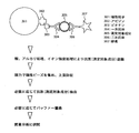
- the antibody is previously bound to the magnetic particles by, for example, an avidin-biotin bond. As shown in FIG.
- the magnetic particles 201 captured through the antibodies 202, 203, 204, and 206 are collected for the measurement target component 205 by the magnetic force of the magnetic body 210, the surrounding contaminants are washed away, and the labeled anti-antibody
- the detection target component is detected and quantified by the detector 211 by performing a sandwich assay with the immunoglobulin antibody.
- This quantitative value includes not only the measurement target component but also the cross-reactivity due to, for example, a structurally similar substance such as a metabolite derived from that component. There is a tendency to show a higher value than the value.
- the component breakdown (relative ratio) of the substances that show cross-reactivity contained in the sample is obtained by mass spectrometry.
- the quantitative value of the component captured from the quantitative value obtained by the immunization method is individually calculated as a value close to the true value.
- the component to be measured is recovered from the sample (waste liquid) used in the immunization method.
- the waste solution after immunoassay is separated from the antigen-antibody reaction by acid treatment, alkali treatment, ionic strength treatment, etc., and the antigen (component to be measured) is released from the antibody.
- the magnetic beads are again collected by the magnetic force of the magnetic particles 301, the supernatant is collected, the solvent is replaced, and then supplied to the mass spectrometry detection system 106.
- the components contained in the supernatant may be separated by a chromatographic technique such as size fractionation, or may be fragmented by enzymatic digestion, if necessary.
- mass analysis is performed on the components contained in the supernatant.
- the signal intensity and peak area for each component are obtained from the obtained chromatogram, and the breakdown of quantitative values measured by the immunization method is calculated for each component based on the relative ratio. Then, the quantitative value calculated by the immunization method is multiplied by the component ratio to correct the quantitative value for each component.
- metabolites of components to be measured are listed as typical examples of structurally similar substances.
- the component to be measured is a therapeutic drug
- the concentration of can be calculated according to the present invention.
- MI 13-o-demethyl type
- M-II 31-o-demethyl type
- M- III 15-o-demethyl type
- M-IV (12-o-hydroxyl type
- MV 15,31-o-demethyl type
- M-VI 13,31-o-demethyl type
- M-VII and M-VIII are known (K. Iwasaki, Drug Metab. Pharmacokinet., 22 (5), 328-335, 2007).
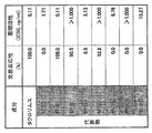
- the cross-reactivity in the enzyme immunoassay with the monoclonal antibody used for the evaluation was 0%, 109%, 90.5%, 8.8%, 92.2%, 0%, 0%, 0%, respectively. Therefore, for example, when tacrolimus concentration in blood is measured by immunization for tacrolimus administered to a patient after organ transplantation using this antibody, not only tacrolimus but also M-II, M- There is a possibility that measurement is performed including metabolites of III, M-IV, and MV.
- M-II and M-IV have both cross-reactivity and immunosuppressive properties. This is because when Iwasaki uses the monoclonal antibody used in the experiment to measure tacrolimus by immunization, it is possible to grasp the blood concentrations of M-II and M-IV together with tacrolimus, the drug to be measured. It becomes essential on.
- FIG. 5 a model for determining each quantitative value of tacrolimus, M-II, and M-IV is shown (FIG. 5).
- the measured values by immunization method (10 ng / ml) and the peak area relative ratios of each component when measured by MS (tacrolimus 100%, M-II 20%, M-IV 10%) are for explanation of the principle. Shall be provisionally set.
- FIG. 5 shows a process up to calculation of a corrected quantitative value of a captured component by MS measurement.
- the measured value when tacrolimus in a patient sample is quantified by immunization is 10 ng / ml
- the chromatogram shows that M-II and M-IV are 100% of the peak area corresponding to tacrolimus.
- the breakdown of the three components (tacrolimus, M-II, M-IV) captured by the immunization method is 76.9% for tacrolimus, 15.4% for M-II, and 7.7% for M-IV.
- the quantitative value 10 ng / ml by immunization method is converted to the breakdown ratio, tacrolimus is 7.7 ng / ml, M-II is 1.5 ng / ml, M-IV is 0.8 ng / ml, and the tacrolimus concentration in the sample is This suggests that the measured value of the immunization method is not 10 ng / ml, but more precisely 7.7 ng / ml excluding the estimated value of the cross-reactive component.
- calculating the quantitative value for each capture component from the ratio of the capture component by MS measurement is only the sum of multiple components due to cross-reactivity that is a problem in the immunization method.
- the breakdown of immunological measurement values can be obtained by determining the abundance of each component captured by the immunization method without the internal standard required for quantitative measurement by the MS method. It is possible to obtain a quantitative value for each component by conversion.
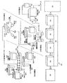
- FIG. 6 is a diagram showing a device configuration example of the sample immunity analysis system 102 shown in FIG.
- the sample 1032 accommodated in the sample rack 1033 is dispensed into the reaction vial 1034 arranged on the reaction table 1035 by the dispensing mechanism 1031.
- the reagent contained in the immunological reagent cartridge 1036 is also dispensed into the reaction vial 1034.
- the reaction vial 1034 is moved from the reaction vial rack 1038 to the reaction table 1035 by the vial moving mechanism 1037.
- the sample supplied from the immunological pretreatment device 103 passes through the cell 1042 including the magnet 1041, is irradiated with light from the light source 1043, and is measured by the photometer 1044. Quantitative data is detected.
- the waste liquid from the photometric detection system 104 for immunization is supplied to the pretreatment device 105 for mass spectrometry.
- the waste liquid from the immunometric photometric detection system 104 is mixed with the dispensed antigen free reagent by the dispensing mechanism 1046, and a free antigen solution is obtained by the action of the magnet 1045.
- the sample substituted by the buffer replacement reagent is supplied to the mass spectrometry detection system 106.
- the mass spectrometry system 106 includes an ion source 1061, a mass analysis unit 1062, and a vacuum pump 1063. Then, mass analysis is performed by the mass spectrometric detection system 106 to obtain spectrum data 108.
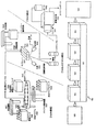
- FIG. 7 is a view showing another device configuration example of the immune analysis system 102 shown in FIG.
- the example shown in FIG. 7 is the same as the example shown in FIG. 6 in the configuration of the pretreatment device for immunization method 103, the pretreatment device for mass spectrometry 105, and the mass spectrometry detection system 106, but the photometry for immunity method.
- the configuration of the detection system 104 is different.
- a magnet 1048 is disposed in the vicinity of the reaction vial 1047 with the cell disposed on the reaction table 1035, and the light from the light source 1043 is transmitted in the reaction vial 1047 with the cell.
- the reagent and the sample are irradiated, and the quantitative data is measured by the photometer 1044.
- the waste liquid of the photometric detection system 104 for immunization is supplied to the pretreatment device 105 for mass spectrometry.
- FIG. 8 is a diagram showing still another device configuration example of the immune analysis system 102 shown in FIG.
- FIG. 8 is the same as the example shown in FIG. 6 in the configuration of the immunological pretreatment device 103 and the mass spectrometry detection system 106, but the immunometric photometric detection system 104 and the mass spectrometry detection system 106 are the same.
- the configuration of the processing device 105 is different.
- the sample after the reaction from the immunological pretreatment device 103 is supplied by the dispensing mechanism 1046 to the cell 1042 in which the magnet 1041 is arranged together with the antigen releasing reagent.
- the sample is irradiated with light from the light source 1043 in the cell 1042 and photometrically measured by the photometer 1044 to detect quantitative data.
- the waste liquid from the photometric detection system 104 for immunization is replaced with a buffer replacement reagent in the pretreatment apparatus 105 for mass spectrometry and supplied to the mass spectrometry detection system 106.
- FIG. 9 is a diagram showing still another device configuration example of the immune analysis system 102 shown in FIG.
- the configuration shown in FIG. 9 is the same as the configuration shown in FIG. 6 in the configuration of the mass spectrometry detection system 106, but the pretreatment device 103 for immunization, the photometric detection system 104 for immunization, and the mass spectrometry detection system
- the configuration of the processing device 105 is different.
- the sample held in the sample rack 1033 is transferred to the reaction table 1035 by the dispensing mechanism 1031.
- the reaction vial 1047 the reagent of the immunological reagent cartridge 1036 is also dispensed.
- the reaction vial 1047 is moved from the reaction vial rack 1038 to the reaction table 1035 by the vial moving mechanism 1037.
- a magnet 1048 is disposed in the vicinity of the reaction vial 1047 with the cell, the light from the light source 1043 is irradiated onto the sample in the reaction vial 1047, and quantitative data is obtained by the photometer 1044.
- a replacement vial 1039 moved from the replacement vial rack 1049 by the vial moving mechanism 1037 is arranged.
- the sample of the reaction vial with cell 1047 is supplied with an antigen releasing reagent, the free antigen solution is supplied from the reaction vial 1047 to the replacement vial 1039, and the solution substituted with the buffer replacement reagent is supplied to the mass spectrometry detection system 106. Is done.
- Example 2 of the present invention will be described.
- Example 2 of the present invention is an example in which a sample for photometric measurement by immunization is applied to component detection by mass spectrometry. Rather than a sandwich assay using a secondary antibody by immunization, a substance to be measured captured by the primary antibody and a similar structural substance such as a metabolite exhibiting cross-reactivity are quantified by mass spectrometry.
- FIG. 10 is a schematic configuration diagram of the entire sample immunity analysis system 502 according to the second embodiment of the present invention, and is a diagram for illustrating a flow of measurement.
- the overall operation of the sample analysis system 502 is controlled by a system control and data processing personal computer 506.
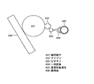
- a component to be measured in a sample 501 derived from a living body is first pretreated by an immunization pretreatment apparatus 503 according to an automatic immunoassay and measured. It is selectively captured by the antibody 604 that specifically recognizes the target component 605.
- the antibody 604 is previously bound to the magnetic particles by, for example, an avidin-biotin bond (602-603).
- the magnetic particles 601 captured through the antibody 604 with respect to the component to be measured are collected by the magnetic force of the magnetic body 606, and surrounding impurities and the like are washed away.
- the captured component includes not only the component to be measured but also the cross-reactivity due to, for example, a structurally similar substance including a metabolite derived from the component, so that only a single component that the antibody should originally recognize is included. Is not limited. Therefore, the component breakdown (relative ratio) in the captured component is determined by mass spectrometry.
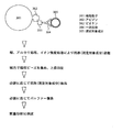
- the component 305 captured by the antigen-antibody reaction is collected by the mass spectrometry pretreatment apparatus 504.
- the antigen-antibody reaction product is separated from the antibody 304 by acid treatment, alkali treatment, ionic strength treatment, etc., and the antigen (measurement target component 305) is released.
- the magnetic beads 301 are collected again by magnetic force, and the supernatant is collected and replaced with a solvent, and then supplied to the mass spectrometry detection system 505.
- the components contained in the supernatant may be separated by a chromatographic technique such as size fractionation, or may be fragmented by enzymatic digestion, if necessary.
- Mass analysis is performed on the components contained in the supernatant in the mass spectrometry detection system 505.
- the signal intensity and peak area for each component are obtained from the obtained chromatogram, and the relative ratio is obtained.
- an internal standard substance may be used to calculate a quantitative value for each component.
- FIG. 13 is a diagram showing a device configuration example of the sample analysis system 502 shown in FIG.
- the sample 5032 accommodated in the sample rack 5033 is dispensed into the reaction vial 5034 arranged on the reaction table 5035 by the dispensing mechanism 5031.
- the reagent contained in the immunological reagent cartridge 5036 is also dispensed into the reaction vial 5034.
- the reaction vial 5034 is moved from the reaction vial rack 5038 to the reaction table 5035 by the vial moving mechanism 5037.
- the solution after the immune reaction supplied from the immunotherapy pretreatment device 503 is mixed with the dispensed antigen releasing reagent by the dispensing mechanism 5046, and the magnet 5045 A free antigen solution is obtained by the action, and the sample substituted with the buffer displacement reagent is supplied to the mass spectrometry detection system 505.
- the mass spectrometry system 505 includes an ion source 5061, a mass analysis unit 5062, and a vacuum pump 5063. Then, mass analysis is performed by the mass spectrometry detection system 505, and spectrum data 507 is obtained.
- FIG. 14 is a diagram showing still another device configuration example of the analysis system 502 shown in FIG.
- the sample held in the sample rack 5033 is divided into reaction vials 5034 arranged on the reaction table 5035 by the dispensing mechanism 5031. Noted.
- the reagent of the immunological reagent cartridge 5036 is also dispensed.
- the reaction vial 5034 is moved from the reaction vial rack 5038 to the reaction table 5035 by the vial moving mechanism 5037.
- a magnet 5048 is disposed in the vicinity of the reaction vial 5034.
- a replacement vial 5039 moved from the replacement vial rack 5049 by the vial moving mechanism 5037 is arranged in the reaction table 5035.
- the sample in the reaction vial 5034 is supplied with an antigen free reagent, the free antigen solution is supplied from the reaction vial 5034 to the replacement vial 5039, and the solution substituted with the buffer replacement reagent is supplied to the mass spectrometry detection system 505. .
- the supernatant (reaction solution) when the magnetic beads are captured by the magnet is solid-phase extracted. Only the measurement target component may be extracted by processing.
- the solid phase extraction agent is selected according to the physical properties of the component to be measured. For example, if the measurement target component and the luminescence detection reagent have different molecular sizes, hydrophobicity, and ionicity, they can be separated and recovered by applying extraction modes such as size fractionation, reverse phase separation, and ion exchange separation. Is possible. In order to carry out such a solid phase extraction treatment, conditions such as the composition, concentration, pH, etc. of the supernatant (reaction solution) may be changed as necessary.
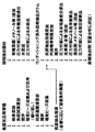
- the immune reaction and solid phase extraction treatment steps are performed in the order shown in FIG.
- FIG. 15 shows the flow of the immune reaction and solid phase extraction treatment.
- the immune reaction includes a step of capturing a component to be measured in a specimen by an antigen-antibody reaction using an immunoreagent, a step of washing and removing contaminant components, and a step of releasing the component to be measured from the immunoreagent.
- solid-phase extraction treatment is a solid-phase extraction packing conditioning process using an organic solvent and H 2 O, a sample test step for the solid-phase extraction packing, and non-specifically adsorbed impurities on the solid-phase extraction packing. And a step of elution and recovery of the target component specifically adsorbed on the solid phase extraction filler.
- the obtained extract can be used for clinical examination by, for example, testing or mass-identifying the components contained in the mass spectrometer.
- the solid phase extraction agent conditioning process is performed in parallel during the immune reaction processing, and the measurement target component obtained by applying the immune reaction is roughly collected. It is necessary to match the timing of obtaining a purified solution (antigen extraction solution) with the timing of completion of conditioning of the solid phase extraction agent.
- the solid phase extraction processing section A starts simultaneously with reaching the immune reaction processing section U.
- Sample 2 and the subsequent samples are processed in the same manner, and the timing of starting them is executed when the previous sample moves to the section T and the section S is vacant.
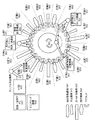
- Fig. 16 shows an example of a top view of a system configuration for automating the solid phase extraction process using a separate solid phase extraction cartridge in which the solid phase extraction column and the recovery device are separated.
- an immune reaction processing container is arranged in eight sections on the concentric circumference of the turntable (cartridge holding section located in sections S to Z). 191 to 978), 14 solid phase extraction cartridges are arranged on the concentric circumference of the turntable (arranged in cartridge holding portions 901 to 914 located in the sections A to N), and the flow shown in FIG. 15 and FIG.
- the steps constituting the immune reaction and the solid-phase extraction process are sequentially performed in parallel on the same circumference.
- a specific operation procedure will be described below by taking blood drug concentration measurement as an example.
- the system is provided with a monitoring mechanism (938) for monitoring the status of the processing process, and operations such as control of the entire system and data analysis are performed by the PC (937).
- the immune reaction process is performed according to the following procedure.
- the immune reaction container is transported to the cartridge holder (971) located in the section S on the turntable by the device moving mechanism.
- the cartridge moves to the cartridge holder (973) located in the section U on the turntable, and the immunoreagent is added.
- the cartridge holding part (975) located in the section W on the turntable collects the magnetic beads that have captured the antigen in the sample with a magnet, removes the reaction solution, and after washing the magnetic beads with the washing liquid, the washing liquid Remove.
- the cartridge holding part (978) located in the section Z on the turntable collects the magnetic beads with a magnet, collects the solution having the released antigen, and conditioned solid phase extraction located in the section F Test the agent.
- the composition (conditions) of the antigen extraction solution may be appropriately adjusted as necessary.
- the used immune reaction container is discarded.
- the solid phase extraction process is performed in the following procedure in parallel with the immune reaction process.
- the solid phase extraction cartridge moving mechanism (941) transfers one solid phase extraction cartridge from the solid phase extraction cartridge stock mechanism (931) to the turntable (921). ) It is transported to the cartridge holding part (901) located in the upper section A.
- This solid-phase extraction cartridge will be referred to as C1 for convenience and will be described below.
- a conditioning organic solvent dispensing mechanism (942) dispenses a certain amount of organic solvent (for example, 100% methanol) to C1.
- the turntable (921) rotates clockwise by one section, and C1 moves to the cartridge holder (903) located in the section C.
- C1 By pressurizing C1 with a pressure application mechanism (943), the organic solvent is passed through the solid phase extraction agent. Waste liquid is collected in a drain or waste liquid collection container and then discarded.
- a conditioning H 2 O dispensing mechanism (942) dispenses a certain amount of H 2 O to C1.
- the turntable (921) rotates clockwise by one section, and C1 moves to the cartridge holder (905) located in the section E.
- C1 By pressurizing C1 with a pressure application mechanism (943), the organic solvent is passed through the solid phase extraction agent. Waste liquid is collected in a drain or waste liquid collection container and then discarded.
- the turntable (921) rotates clockwise by one section, and C1 moves to the cartridge holder (906) located in the section F. Test the antigen extraction solution collected in compartment Z against C1.
- an internal standard substance dispensing mechanism (942) collects and dispenses a certain amount of internal standard substance from the internal standard substance container placed at the internal standard substance dispensing position of the internal standard substance arrangement mechanism (933). To do.
- the turntable (921) rotates clockwise by one section, and C1 moves to the cartridge holder (908) located in the section H.
- the specimen and the internal standard substance are stirred with respect to C1 by the stirring mechanism (944).
- the turntable (921) rotates clockwise by one section, and C1 moves to the cartridge holder (909) located in the section I.
- C1 By pressurizing C1 with a pressure applying mechanism (943), the mixed solution of the specimen and the internal standard substance is passed through the solid phase extraction agent. Waste liquid is collected in a drain or waste liquid collection container and then discarded.
- the turntable (921) rotates clockwise by one section, and C1 moves to the cartridge holder (910) located in the section J.
- a cleaning liquid dispensing mechanism (942) dispenses a certain amount of cleaning liquid into C1.
- the turntable (921) rotates clockwise by one section, and C1 moves to the cartridge holder (911) located in the section K.
- C1 By pressurizing C1 with a pressure applying mechanism (943), the cleaning liquid is passed through the solid phase extraction agent. Waste liquid is collected in a drain or waste liquid collection container and then discarded.
- the turntable (921) rotates clockwise by one section, and C1 moves to the cartridge holder (912) located in the section L.
- the eluate dispensing mechanism (942) dispenses a certain amount of eluate to C1.
- FIG. 17 shows a side view of the system configuration in the partition M.
- the eluate discharged from the solid-phase extraction cartridge (1001) C1 is collected by the collection container (1002) standing by at a position immediately below the C1 discharge port on the collection container arrangement mechanism (934, 1006).
- the recovery container (1002) that recovered the eluate is moved to a predetermined position of the recovery container installation mechanism (934, 1006), and then the eluate is analyzed by the mass spectrometer (936, 1007). ) And quantitate while separating the target components in the eluate.
- a dispensing mechanism absorbs a required amount of the extract and introduces it directly or indirectly (for example, flow injection method) into the ion source of MS. .
- the turntable (921) rotates clockwise by one section, and C1 moves to the cartridge holder (914) located in the section N.
- the solid phase extraction cartridge moving mechanism (941) collects C1 from the turntable (921) and discards it in the cartridge discarding unit (935).
- the recovery container after the solid phase extraction process can be stored by being removed from the turntable by the recovery arm instead of being discarded.
- the collection container during storage may be capped at the top of the collection container as necessary to avoid drying the extract. Even when dried, re-measurement can be performed by re-dissolving with a solvent.
- the amount of solvent added at that time is controlled to a value obtained by subtracting the volume consumed for the measurement from, for example, the monitoring value of the liquid level (or volume) of the extract during solid phase extraction.
- a new solid phase extraction cartridge (1001) C2 ( Tentative name) is input, and processing of the second sample is started by C2 with a delay of one section (work) following C1. Since the third and subsequent samples are similarly processed subsequent to C2, a total of 14 samples corresponding to the number of sections are sequentially processed in parallel on the turntable (921). The case of re-inspection is processed in the same manner.
- the present invention is effective for improving the accuracy of measurement data by an immunization method, and can be widely applied to various fields such as basic research fields, medical treatment, drug discovery, testing, and diagnosis.
- the present invention can solve the problems of the immunization method and mass spectrometry by complementing each other, and can provide a highly accurate and highly reliable clinical test result.
- the deviation from the true value caused by the cross-reactivity is corrected by obtaining the relative ratio of the quantification component breakdown by the mass spectrometry method.
- the quantitative values of the cross-reaction component and the measurement target component that cannot be obtained by the immunization method are individually obtained.
- replacement vial 1 41, 1045, 1048, 5045, 5048 ... magnet, 1042 ... cell, 1043 ... light source, 1044 ... photometer, 1047 ... reaction vial with cell, 1049, 5049 ... for replacement Vial rack, 1061, 5061 ... ion source, 1062, 5062 ... mass analyzer, 1063, 5063 ... vacuum pump
Landscapes
- Life Sciences & Earth Sciences (AREA)
- Health & Medical Sciences (AREA)
- Engineering & Computer Science (AREA)
- Molecular Biology (AREA)
- Physics & Mathematics (AREA)
- Bioinformatics & Cheminformatics (AREA)
- Bioinformatics & Computational Biology (AREA)
- Chemical & Material Sciences (AREA)
- Urology & Nephrology (AREA)
- Immunology (AREA)
- Biomedical Technology (AREA)
- Hematology (AREA)
- Cell Biology (AREA)
- Medicinal Chemistry (AREA)
- Proteomics, Peptides & Aminoacids (AREA)
- Microbiology (AREA)
- Biophysics (AREA)
- Spectroscopy & Molecular Physics (AREA)
- Food Science & Technology (AREA)
- Biotechnology (AREA)
- Analytical Chemistry (AREA)
- Biochemistry (AREA)
- General Health & Medical Sciences (AREA)
- General Physics & Mathematics (AREA)
- Pathology (AREA)
- Other Investigation Or Analysis Of Materials By Electrical Means (AREA)
- Automatic Analysis And Handling Materials Therefor (AREA)
Abstract
Description
Claims (24)
- 免疫分析法による前処理により、試料溶液中の測定対象物(101、501、1032)を抗体を用いて捕捉し、
捕捉した測定対象物(101、501、1032)の定量を行い、
測定対象物の定量を行った廃液から上記測定対象物(101、501、1032)を回収し、
回収した測定対象物を質量分析法により、質量分析を行い、上記免疫法により行った測定対象物の成分を測定することを特徴とする免疫分析方法。 - 請求項1記載の免疫分析方法において、免疫分析法による前処理(103)により、試料溶液中の測定対象物を一次抗体(204)、二次抗体(206)及び磁性粒子(201)を用いて捕捉し、捕捉した測定対象物に光を照射して測定対象物の定量を行うことを特徴とする免疫分析方法。
- 請求項2記載の免疫分析方法において、上記定量が行われた測定対象物の回収は、一次抗体(204)、二次抗体(206)及び磁性粒子(201)を用いて回収することを特徴とする免疫分析方法。
- 請求項2記載の免疫分析方法において、上記質量分析法により、上記免疫法により行った測定対象物の成分比率を算出し、上記免疫法で算出した定量値に対して上記成分比率を掛け合わせることにより、成分毎の定量値を補正することを特徴とする免疫分析方法。
- 請求項1記載の免疫分析方法において、上記測定対象物の定量を行った廃液から抗原抗体反応により抗原を捕捉し、捕捉した抗原を遊離化した後に回収し、回収した測定対象物を質量分析法により、質量分析を行うことを特徴とする免疫分析方法。
- 免疫分析法による前処理(103)により、試料溶液中の測定対象物(101、501、1032)を抗体を用いて捕捉し、
捕捉した測定対象物から測定対象成分を回収し、
回収した測定対象成分を質量分析法により、質量分析を行い、測定対象物の成分の分析を行うことを特徴とする免疫分析方法。 - 請求項6記載の免疫分析方法において、免疫分析法による前処理(103)により、試料溶液中の測定対象物を一次抗体(204)、二次抗体(206)及び磁性粒子(201)を用いて捕捉することを特徴とする免疫分析方法。
- 請求項7記載の免疫分析方法において、上記測定対象物からの測定対象成分の回収は、一次抗体(204)、二次抗体(206)及び磁性粒子(201)を用いて回収することを特徴とする免疫分析方法。
- 請求項7記載の免疫分析方法において、上記測定対象物から抗原抗体反応により抗原を捕捉し、捕捉した抗原を遊離化した後に回収し、回収した測定対象成分を質量分析法により、質量分析を行うことを特徴とする免疫分析方法。
- 請求項9記載の免疫分析方法において、上記測定対象物から抗原抗体反応により抗原を捕捉し、捕捉した抗原を遊離化した後に回収する工程を固相抽出処理で行うことを特徴とする免疫分析方法。
- 免疫分析システムにおいて、
免疫分析法による前処理により、試料溶液中の測定対象物を抗体を用いて捕捉する免疫法用前処理手段(103)と、
捕捉した測定対象物の定量を行う免疫法用検出手段(104)と、
測定対象物の定量を行った廃液から上記測定対象物を回収する質量分析法用前処理手段(105)と、
回収した測定対象物を質量分析法により、質量分析を行い、上記免疫法により行った測定対象物の成分を測定する質量分析手段(106)と、
を備えることを特徴とする免疫分析システム。 - 請求項11記載の免疫分析システムにおいて、上記免疫法用前処理手段(103)は、試料溶液中の測定対象物を一次抗体(204)、二次抗体(206)及び磁性粒子(201)を用いて捕捉し、上記免疫法用検出手段(104)は、捕捉した測定対象物に光を照射して測定対象物の定量を行うことを特徴とする免疫分析システム。
- 請求項12記載の免疫分析システムにおいて、上記質量分析法用前処理手段(105)は、測定対象物を、一次抗体(204)、二次抗体(206)及び磁性粒子(201)を用いて回収することを特徴とする免疫分析システム。
- 請求項12記載の免疫分析システムにおいて、上記質量分析手段(106)は、上記免疫法により行った測定対象物の成分比率を算出し、上記免疫法用検出手段(104)が算出した定量値に対して上記成分比率を掛け合わせることにより、成分毎の定量値を補正することを特徴とする免疫分析システム
- 請求項11記載の免疫分析システムにおいて、上記質量分析法用前処理手段(105)は上記免疫法用検出手段(104)が測定対象物の定量を行った廃液から抗原抗体反応により抗原を捕捉し、捕捉した抗原を遊離化した後に回収することを特徴とする免疫分析システム。
- 免疫分析システムにおいて、
免疫分析法による前処理により、試料溶液中の測定対象物を抗体を用いて捕捉する免疫法用前処理手段(103)と、
捕捉した測定対象物から上記測定対象物を回収する質量分析法用前処理手段(105)と、
回収した測定対象物を質量分析法により、質量分析を行い、上記免疫法により行った測定対象物の成分を測定する質量分析手段(106)と、
を備えることを特徴とする免疫分析システム。 - 請求項16記載の免疫分析システムにおいて、上記免疫法用前処理手段(103)は、試料溶液中の測定対象物を一次抗体(204)、二次抗体(206)及び磁性粒子(201)を用いて捕捉することを特徴とする免疫分析システム。
- 請求項17記載の免疫分析システムにおいて、上記質量分析法用前処理手段(105)は、測定対象物を、一次抗体(204)、二次抗体(206)及び磁性粒子(201)を用いて回収することを特徴とする免疫分析システム。
- 請求項16記載の免疫分析システムにおいて、上記質量分析法用前処理手段(105)は上記測定対象物から抗原抗体反応により抗原を捕捉し、捕捉した抗原を遊離化した後に回収することを特徴とする免疫分析システム。
- [規則91に基づく訂正 11.06.2010]
請求項19記載の免疫分析システムにおいて、上記測定対象物から抗原抗体反応により抗原を捕捉し、捕捉した抗原を遊離化した後に回収する工程を固相抽出処理で行うことを特徴とする免疫分析システム。 - 請求項20記載の免疫分析システムにおいて、固相抽出処理を無限軌道上で自動処理することを特徴とする免疫分析システム。
- 請求項20記載の免疫分析システムにおいて、目的が異なる複数の処理工程として、固相抽出処理および免疫反応処理を、同一の無限軌道上で並行して自動処理することを特徴とする免疫分析システム。
- 請求項20記載の免疫分析システムにおいて、免疫反応により粗精製した抗原を遊離回収した溶液を得る工程と、その溶液をコンディショニング済みの固相抽出剤に供試することが同期することを特徴とする免疫分析システム。
- 請求項20記載の免疫分析システムにおいて、免疫反応により粗精製した抗原を遊離回収した溶液を回収する分注機構と、その溶液をコンディショニング済みの固相抽出剤に供試する分注機構が同一であることを特徴とする免疫分析システム。
Priority Applications (4)
| Application Number | Priority Date | Filing Date | Title |
|---|---|---|---|
| JP2010550523A JP5529051B2 (ja) | 2009-02-10 | 2010-02-09 | 質量分析技術を用いた免疫分析方法および免疫分析システム |
| DE112010000814.0T DE112010000814B4 (de) | 2009-02-10 | 2010-02-09 | Immunanalytisches Verfahren und immunanalytisches System mit Verwendung der Massenspektrometertechnologie |
| US13/146,952 US8865418B2 (en) | 2009-02-10 | 2010-02-09 | Immunoanalytical method and system using mass spectrometry technology |
| CN201080007256.5A CN102308215B (zh) | 2009-02-10 | 2010-02-09 | 使用了质谱分析技术的免疫分析方法和免疫分析系统 |
Applications Claiming Priority (2)
| Application Number | Priority Date | Filing Date | Title |
|---|---|---|---|
| JP2009-029111 | 2009-02-10 | ||
| JP2009029111 | 2009-02-10 |
Publications (1)
| Publication Number | Publication Date |
|---|---|
| WO2010092958A1 true WO2010092958A1 (ja) | 2010-08-19 |
Family
ID=42561800
Family Applications (1)
| Application Number | Title | Priority Date | Filing Date |
|---|---|---|---|
| PCT/JP2010/051904 Ceased WO2010092958A1 (ja) | 2009-02-10 | 2010-02-09 | 質量分析技術を用いた免疫分析方法および免疫分析システム |
Country Status (5)
| Country | Link |
|---|---|
| US (1) | US8865418B2 (ja) |
| JP (1) | JP5529051B2 (ja) |
| CN (1) | CN102308215B (ja) |
| DE (1) | DE112010000814B4 (ja) |
| WO (1) | WO2010092958A1 (ja) |
Cited By (7)
| Publication number | Priority date | Publication date | Assignee | Title |
|---|---|---|---|---|
| JP2012189395A (ja) * | 2011-03-09 | 2012-10-04 | Jnc Corp | 検出対象の検出方法および定量方法 |
| US20140295430A1 (en) * | 2011-10-05 | 2014-10-02 | Hitachi High-Technologies Corporation | Method for analyzing biomolecules and biomolecule analyzer |
| WO2016006398A1 (ja) * | 2014-07-07 | 2016-01-14 | 株式会社 日立ハイテクノロジーズ | 分析装置および分析方法 |
| WO2019131380A1 (ja) * | 2017-12-25 | 2019-07-04 | 富士レビオ株式会社 | マクロライド系免疫抑制剤についての血液検査方法 |
| JP2020521958A (ja) * | 2017-05-22 | 2020-07-27 | ベックマン コールター, インコーポレイテッド | 複数の検出能力を有する統合試料処理システム |
| JPWO2021065105A1 (ja) * | 2019-09-30 | 2021-04-08 | ||
| WO2021152966A1 (ja) * | 2020-01-31 | 2021-08-05 | 富士フイルム株式会社 | イムノクロマトグラフィー |
Families Citing this family (2)
| Publication number | Priority date | Publication date | Assignee | Title |
|---|---|---|---|---|
| CN104749159A (zh) * | 2013-12-30 | 2015-07-01 | 同方威视技术股份有限公司 | 农药残留检测方法 |
| WO2020084886A1 (ja) * | 2018-10-25 | 2020-04-30 | 株式会社日立ハイテク | 自動分析装置 |
Citations (3)
| Publication number | Priority date | Publication date | Assignee | Title |
|---|---|---|---|---|
| JPH11201953A (ja) * | 1998-01-14 | 1999-07-30 | Toyota Central Res & Dev Lab Inc | 固相抽出装置用カートリッジ |
| JP2005524394A (ja) * | 2002-04-12 | 2005-08-18 | コロラド・スクール・オブ・マインズ | 標的細菌性細胞を感染させるためにファージを使用する低濃度の標的細菌を検出するための方法 |
| JP2008532984A (ja) * | 2005-03-09 | 2008-08-21 | コンセホ スペリオール デ インベスティガシオネス シエンティフィカス | モノクローナル抗体を使用するアルツハイマー病のinvitro診断の方法 |
Family Cites Families (10)
| Publication number | Priority date | Publication date | Assignee | Title |
|---|---|---|---|---|
| JPS63118665A (ja) * | 1986-11-06 | 1988-05-23 | Toshiba Corp | 自動化学分析装置のサンプル希釈方法 |
| JP3481705B2 (ja) * | 1994-12-12 | 2003-12-22 | 株式会社モリテックス | 自動固相抽出装置 |
| JPH1123546A (ja) * | 1997-06-30 | 1999-01-29 | Shimadzu Corp | 液体クロマトグラフィのサンプル注入方法および装置 |
| US20020192676A1 (en) * | 2001-06-18 | 2002-12-19 | Madonna Angelo J. | Method for determining if a type of bacteria is present in a mixture |
| AU2003272924B2 (en) | 2002-10-04 | 2008-05-15 | Protosera Inc. | Plate for mass spectrometry, process for preparing the same and use thereof |
| JP2005098830A (ja) | 2003-09-25 | 2005-04-14 | Institute Of Physical & Chemical Research | 質量分析法によるタンパク質相互作用物質のスクリーニング方法 |
| JP4522739B2 (ja) | 2004-03-31 | 2010-08-11 | 株式会社堀場製作所 | 液体試料の濃縮方法及び濃縮用保持台とそれを用いた微量元素分析方法 |
| JP2006126013A (ja) | 2004-10-28 | 2006-05-18 | Shimadzu Corp | プロテオーム解析装置 |
| CN101191795A (zh) * | 2006-11-27 | 2008-06-04 | 许洋 | 免疫组质谱检测消化系统肿瘤生物标志群的试剂盒和方法 |
| JP4983803B2 (ja) * | 2006-11-29 | 2012-07-25 | 株式会社島津製作所 | 免疫沈降を用いた生体試料の質量分析法 |
-
2010
- 2010-02-09 JP JP2010550523A patent/JP5529051B2/ja not_active Expired - Fee Related
- 2010-02-09 DE DE112010000814.0T patent/DE112010000814B4/de not_active Expired - Fee Related
- 2010-02-09 WO PCT/JP2010/051904 patent/WO2010092958A1/ja not_active Ceased
- 2010-02-09 CN CN201080007256.5A patent/CN102308215B/zh not_active Expired - Fee Related
- 2010-02-09 US US13/146,952 patent/US8865418B2/en not_active Expired - Fee Related
Patent Citations (3)
| Publication number | Priority date | Publication date | Assignee | Title |
|---|---|---|---|---|
| JPH11201953A (ja) * | 1998-01-14 | 1999-07-30 | Toyota Central Res & Dev Lab Inc | 固相抽出装置用カートリッジ |
| JP2005524394A (ja) * | 2002-04-12 | 2005-08-18 | コロラド・スクール・オブ・マインズ | 標的細菌性細胞を感染させるためにファージを使用する低濃度の標的細菌を検出するための方法 |
| JP2008532984A (ja) * | 2005-03-09 | 2008-08-21 | コンセホ スペリオール デ インベスティガシオネス シエンティフィカス | モノクローナル抗体を使用するアルツハイマー病のinvitro診断の方法 |
Cited By (22)
| Publication number | Priority date | Publication date | Assignee | Title |
|---|---|---|---|---|
| JP2012189395A (ja) * | 2011-03-09 | 2012-10-04 | Jnc Corp | 検出対象の検出方法および定量方法 |
| US20140295430A1 (en) * | 2011-10-05 | 2014-10-02 | Hitachi High-Technologies Corporation | Method for analyzing biomolecules and biomolecule analyzer |
| US9822399B2 (en) * | 2011-10-05 | 2017-11-21 | Hitachi High-Technologies Corporation | Method for analyzing biomolecules and biomolecule analyzer |
| GB2550631B (en) * | 2014-07-07 | 2020-07-29 | Hitachi High Tech Corp | Analysis device and analysis method |
| WO2016006398A1 (ja) * | 2014-07-07 | 2016-01-14 | 株式会社 日立ハイテクノロジーズ | 分析装置および分析方法 |
| JPWO2016006398A1 (ja) * | 2014-07-07 | 2017-04-27 | 株式会社日立ハイテクノロジーズ | 分析装置および分析方法 |
| GB2550631A (en) * | 2014-07-07 | 2017-11-29 | Hitachi High Tech Corp | Analysis device and analysis method |
| US10585089B2 (en) | 2014-07-07 | 2020-03-10 | Hitachi High-Technologies Corporation | Analysis device and analysis method |
| US11402386B2 (en) | 2017-05-22 | 2022-08-02 | Beckman Coulter, Inc. | Integrated sample processing system with multiple detection capability |
| JP2020521958A (ja) * | 2017-05-22 | 2020-07-27 | ベックマン コールター, インコーポレイテッド | 複数の検出能力を有する統合試料処理システム |
| JP2024133264A (ja) * | 2017-05-22 | 2024-10-01 | ベックマン コールター, インコーポレイテッド | 複数の検出能力を有する統合試料処理システム |
| JP7325336B2 (ja) | 2017-12-25 | 2023-08-14 | 富士レビオ株式会社 | マクロライド系免疫抑制剤についての血液検査方法 |
| WO2019131380A1 (ja) * | 2017-12-25 | 2019-07-04 | 富士レビオ株式会社 | マクロライド系免疫抑制剤についての血液検査方法 |
| JPWO2019131380A1 (ja) * | 2017-12-25 | 2020-12-24 | 富士レビオ株式会社 | マクロライド系免疫抑制剤についての血液検査方法 |
| US12196768B2 (en) | 2017-12-25 | 2025-01-14 | Fujirebio Inc. | Method of testing a blood for macrolide immunosuppressant |
| WO2021065105A1 (ja) * | 2019-09-30 | 2021-04-08 | 富士フイルム株式会社 | イムノクロマトグラフィー |
| JP7148738B2 (ja) | 2019-09-30 | 2022-10-05 | 富士フイルム株式会社 | イムノクロマトグラフィー |
| JPWO2021065105A1 (ja) * | 2019-09-30 | 2021-04-08 | ||
| US12613240B2 (en) | 2019-09-30 | 2026-04-28 | Fujifilm Corporation | Immunochromatography |
| WO2021152966A1 (ja) * | 2020-01-31 | 2021-08-05 | 富士フイルム株式会社 | イムノクロマトグラフィー |
| JPWO2021152966A1 (ja) * | 2020-01-31 | 2021-08-05 | ||
| JP7257556B2 (ja) | 2020-01-31 | 2023-04-13 | 富士フイルム株式会社 | イムノクロマトグラフィー |
Also Published As
| Publication number | Publication date |
|---|---|
| JPWO2010092958A1 (ja) | 2012-08-16 |
| DE112010000814B4 (de) | 2021-09-09 |
| CN102308215A (zh) | 2012-01-04 |
| DE112010000814T5 (de) | 2012-02-09 |
| US8865418B2 (en) | 2014-10-21 |
| JP5529051B2 (ja) | 2014-06-25 |
| CN102308215B (zh) | 2014-06-25 |
| US20110287446A1 (en) | 2011-11-24 |
Similar Documents
| Publication | Publication Date | Title |
|---|---|---|
| JP5529051B2 (ja) | 質量分析技術を用いた免疫分析方法および免疫分析システム | |
| CN111670363B (zh) | 具有可变工作流的集成样品处理系统 | |
| JP5396534B2 (ja) | 分析装置 | |
| JP6307607B2 (ja) | 分析装置および分析方法 | |
| JP5519538B2 (ja) | サンプルの前処理装置、及びそれを備えた質量分析装置 | |
| CN102326073B (zh) | 分析装置 | |
| Trbojević-Akmačić et al. | Comparative analysis and validation of different steps in glycomics studies | |
| CN110832299A (zh) | 自动化临床诊断系统和方法 | |
| EP2545370B1 (en) | Method for recognition and quantification of multiple analytes in a single analysis | |
| US8455202B2 (en) | Affinity selector based recognition and quantification system and method for multiple analytes in a single analysis | |
| JP7046070B2 (ja) | 分析系におけるプロセス中に試薬を同定するための方法 | |
| CN104160278A (zh) | 基于选择剂的识别和量化系统及用于在单次分析中识别和量化多种分析物的方法 | |
| JP7520824B2 (ja) | 自動分析装置の前処理方法 | |
| CN102375063A (zh) | 一种常见蛋白质的免疫质谱试剂盒及制备方法 | |
| US20150105280A1 (en) | Selector based recognition and quantification system and method for multiple analytes in a single analysis | |
| Hanzawa et al. | HGA Segment 2: Automation of sample preparation in rapid glycoproteomics | |
| JPH03252555A (ja) | 生体試料の分析方法および分析装置 | |
| WO2026083691A1 (ja) | 自動分析装置 | |
| JP2023550279A (ja) | 患者試料における質量分析測定のための少なくとも1つの目的の分析物の誘導体化 |
Legal Events
| Date | Code | Title | Description |
|---|---|---|---|
| WWE | Wipo information: entry into national phase |
Ref document number: 201080007256.5 Country of ref document: CN |
|
| 121 | Ep: the epo has been informed by wipo that ep was designated in this application |
Ref document number: 10741235 Country of ref document: EP Kind code of ref document: A1 |
|
| WWE | Wipo information: entry into national phase |
Ref document number: 2010550523 Country of ref document: JP |
|
| WWE | Wipo information: entry into national phase |
Ref document number: 13146952 Country of ref document: US |
|
| WWE | Wipo information: entry into national phase |
Ref document number: 1120100008140 Country of ref document: DE Ref document number: 112010000814 Country of ref document: DE |
|
| 122 | Ep: pct application non-entry in european phase |
Ref document number: 10741235 Country of ref document: EP Kind code of ref document: A1 |