WO2010092732A1 - エンジン - Google Patents
エンジン Download PDFInfo
- Publication number
- WO2010092732A1 WO2010092732A1 PCT/JP2009/071167 JP2009071167W WO2010092732A1 WO 2010092732 A1 WO2010092732 A1 WO 2010092732A1 JP 2009071167 W JP2009071167 W JP 2009071167W WO 2010092732 A1 WO2010092732 A1 WO 2010092732A1
- Authority
- WO
- WIPO (PCT)
- Prior art keywords
- engine
- rotational speed
- control
- speed
- engine speed
- Prior art date
- Legal status (The legal status is an assumption and is not a legal conclusion. Google has not performed a legal analysis and makes no representation as to the accuracy of the status listed.)
- Ceased
Links
Images


Classifications
-
- F—MECHANICAL ENGINEERING; LIGHTING; HEATING; WEAPONS; BLASTING
- F02—COMBUSTION ENGINES; HOT-GAS OR COMBUSTION-PRODUCT ENGINE PLANTS
- F02D—CONTROLLING COMBUSTION ENGINES
- F02D41/00—Electrical control of supply of combustible mixture or its constituents
- F02D41/30—Controlling fuel injection
- F02D41/38—Controlling fuel injection of the high pressure type
- F02D41/40—Controlling fuel injection of the high pressure type with means for controlling injection timing or duration
- F02D41/401—Controlling injection timing
-
- F—MECHANICAL ENGINEERING; LIGHTING; HEATING; WEAPONS; BLASTING
- F02—COMBUSTION ENGINES; HOT-GAS OR COMBUSTION-PRODUCT ENGINE PLANTS
- F02D—CONTROLLING COMBUSTION ENGINES
- F02D41/00—Electrical control of supply of combustible mixture or its constituents
- F02D41/02—Circuit arrangements for generating control signals
- F02D41/04—Introducing corrections for particular operating conditions
- F02D41/06—Introducing corrections for particular operating conditions for engine starting or warming up
- F02D41/062—Introducing corrections for particular operating conditions for engine starting or warming up for starting
- F02D41/064—Introducing corrections for particular operating conditions for engine starting or warming up for starting at cold start
-
- F—MECHANICAL ENGINEERING; LIGHTING; HEATING; WEAPONS; BLASTING
- F02—COMBUSTION ENGINES; HOT-GAS OR COMBUSTION-PRODUCT ENGINE PLANTS
- F02D—CONTROLLING COMBUSTION ENGINES
- F02D41/00—Electrical control of supply of combustible mixture or its constituents
- F02D41/02—Circuit arrangements for generating control signals
- F02D41/021—Introducing corrections for particular conditions exterior to the engine
- F02D41/0215—Introducing corrections for particular conditions exterior to the engine in relation with elements of the transmission
- F02D41/0225—Introducing corrections for particular conditions exterior to the engine in relation with elements of the transmission in relation with the gear ratio or shift lever position
-
- Y—GENERAL TAGGING OF NEW TECHNOLOGICAL DEVELOPMENTS; GENERAL TAGGING OF CROSS-SECTIONAL TECHNOLOGIES SPANNING OVER SEVERAL SECTIONS OF THE IPC; TECHNICAL SUBJECTS COVERED BY FORMER USPC CROSS-REFERENCE ART COLLECTIONS [XRACs] AND DIGESTS
- Y02—TECHNOLOGIES OR APPLICATIONS FOR MITIGATION OR ADAPTATION AGAINST CLIMATE CHANGE
- Y02T—CLIMATE CHANGE MITIGATION TECHNOLOGIES RELATED TO TRANSPORTATION
- Y02T10/00—Road transport of goods or passengers
- Y02T10/10—Internal combustion engine [ICE] based vehicles
- Y02T10/40—Engine management systems
Definitions
- the present invention relates to an engine technology, and more particularly to an engine technology provided with a control device that performs engine speed control at the time of engine cold start.
- the present invention provides an engine that can improve the combustion efficiency of fuel and reduce the amount of black smoke generated at the time of engine cold start.
- coolant temperature detecting means for cooling the engine engine speed detecting means, switching means for switching the clutch mechanism, engine speed setting means for determining the set engine speed, And a control device capable of automatically controlling the target engine speed, wherein the control device determines the target engine speed when the coolant temperature at the time of starting the engine is equal to or lower than a predetermined temperature.
- Rotational speed correction control for setting the engine rotational speed higher than the set engine rotational speed set by the means is performed.
- control device cancels the rotational speed correction control when the coolant temperature at the time of starting the engine reaches a predetermined temperature.
- the control device when performing the rotational speed correction control, rotates based on the engine rotational speed at the start of the rotational speed correction control and the rotational speed correction map stored in the storage device provided in the control device. Perform number correction control.
- the control device switches the clutch mechanism to “ON” and then rotates the rotational speed.
- the correction control is canceled, and the rotation speed correction release control is performed based on the engine rotation speed when the clutch mechanism is switched to “ON” and the rotation speed correction map stored in the storage device provided in the control device. .
- the control device when the rotation speed correction release control is performed, the control device does not perform the rotation speed correction control unless the engine is once stopped and then restarted.
- the rotational speed correction control is not performed.
- the fuel combustion efficiency can be improved, and the amount of black smoke discharged immediately after the cold start can be reduced. Moreover, the engine temperature rise can be promoted, and the disappearance of black smoke can be accelerated.
- the engine when the engine temperature rises as a result of increasing the engine speed, the engine can be operated at the set engine speed set by the operator.
- the engine speed can be smoothly shifted by controlling the amount of change in the engine speed at the cold start.
- the clutch mechanism after the clutch mechanism is switched to “ON”, the amount of change in the engine speed is controlled, so that the engine speed can be gradually decreased to shift to the set engine speed. For this reason, when an engine is an engine which drives a propulsion unit as a marine engine, for example, deterioration of ship maneuverability can be prevented.
- FIG. 1 is a schematic plan view showing an overall configuration of an engine according to an embodiment of the present invention.
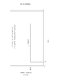
- the graph which shows the relationship between engine rotation speed and cooling water temperature, and time.
- the graph which shows the relationship between engine rotation speed and cooling water temperature, and time.
- the graph which shows the relationship between engine rotation speed and cooling water temperature, and time.
- the graph which shows the relationship between engine rotation speed and cooling water temperature, and time.
- Engine 100 is an engine that is mounted on a ship and drives propulsion unit 110 as a marine engine. In addition, it is not limited to the engine which drives the propulsion unit 110 as a marine engine, It can also be comprised with the engine used for another use.
- the engine 100 also includes an engine body 10 and a control device 20 that performs advance control of fuel injection timing.
- the engine body 10 is a diesel engine.
- the output shaft 11 of the engine body 10 is connected to the propulsion unit 110.
- a flywheel 12 is provided on the output shaft 11 of the engine body 10.
- the propulsion unit 110 is a unit that drives the propeller 111 through a transmission mechanism (not shown) by driving the output shaft 11.
- a clutch mechanism 23 is provided for connecting / disconnecting between the output shaft and the propulsion unit and switching between normal rotation and reverse rotation.
- the clutch mechanism 23 is constituted by a hydraulic clutch or the like and is connected to the control device 20 to be turned on / off.
- the engine main body 10 includes a fuel injection pump 21 that is a fuel injection device, and injectors 22, 22, 22, 22.
- the fuel is pumped by the fuel injection pump 21 and injected into each cylinder by the injectors 22, 22, 22, 22.
- the control device 20 is a device that performs advance control of the fuel injection timing when acceleration occurs in the engine low speed range.
- the control device 20 includes an engine control unit (hereinafter referred to as ECU) 40, an accelerator operation detection means 41, a clutch operation detection means 42 as a switching means, an engine speed sensor 44, a rack actuator 46, and a selection means.
- a contact input device 47 and a water temperature sensor 48 are connected to each other.
- the ECU 40 includes an arithmetic device 50 and a storage device 51.
- the accelerator operation detection means 41 and the clutch operation detection means 42 are provided at the steering seat of the ship.
- the accelerator operation detecting means 41 is provided at the rotation base of the accelerator lever for setting the engine speed, and has a function of inputting the set engine speed Nset to the ECU 40.
- the clutch operation detection means 42 is provided at the rotation base of the clutch lever that performs connection / disconnection and forward / reverse switching operation of the clutch mechanism 23, and inputs a detection signal of the rotation operation to the ECU 40 to receive the clutch mechanism 23. Switch.
- the engine speed sensor 44 is provided in the vicinity of the output shaft 11 of the engine 100.
- the engine speed sensor 44 has a function of detecting the actual engine speed Ne and transmitting it to the ECU 40 as actual engine speed detection means.
- the rack actuator 46 is a device that adjusts the fuel injection amount based on the target injection amount.
- the contact input device 47 has a function of selecting or setting various functions of the engine 100 as selection means.
- the water temperature sensor 48 has a function of detecting the temperature T of cooling water used for cooling the engine 100 and transmitting it to the ECU.
- the water temperature sensor 48 is provided, for example, in a cooling water passage (not shown), and detects the water temperature T of the cooling water that varies depending on the outside air and the operating state of the engine.
- the coolant temperature T detected by the water temperature sensor 48 at the time t1 when the engine start is recognized after the time t0 when the engine start is started is the lower limit water temperature T1.
- the ECU 40 of the control device 20 increases the final target engine speed Nsetf to a corrected target engine speed Nset ′ that is higher than the set engine speed Nset.
- the ECU 40 of the control device 20 corrects the rotational speed. Do not control.
- the combustion efficiency of the injected fuel can be improved and the amount of black smoke discharged immediately after the cold start can be reduced. Further, the temperature increase of engine 100 can be promoted, and the disappearance of black smoke can be accelerated. Further, when the clutch mechanism 23 is connected and switched to “ON” by operating the clutch operation detecting means 42 during the rotational speed correction control, the final target engine rotational speed Nsetf is set to the corrected target engine rotational speed Nset. Therefore, the amount of decrease in engine speed at the time of switching can be reduced, and the maneuverability can be improved.
- the ECU 40 of the control device 20 sets the final target engine rotation speed Nsetf by the accelerator operation detection means 41.
- Rotational speed correction release control is set to the same value as the rotational speed Nset.
- the ECU 40 of the control device 20 starts from that time t2.
- the final target engine speed Nsetf is set to the same value as the set engine speed Nset input by the accelerator operation detecting means 41.
- the ECU 40 of the control device 20 Rotational speed correction cancellation control for setting the final target engine rotational speed Nsetf to the same value as the set engine rotational speed Nset input by the accelerator operation detecting means 41 is performed.
- the rotational speed correction release control as shown in FIG. 4, when the clutch mechanism 23 is connected and switched to “ON”, the set engine speed in which the operator inputs the final target engine rotational speed Nsetf from that time t3.
- the engine speed is not more than several Nset. As a result, the ship can be operated at the engine speed expected by the operator.
- the ECU 40 of the control device 20 does not stop the engine once and then restarts the rotational speed. Does not perform correction control.
- the clutch mechanism 23 when the clutch mechanism 23 is once connected and switched to “ON”, and after performing the rotational speed correction release control, the clutch mechanism 23 is disconnected and switched to “OFF”. Even when the coolant temperature T at the time point t4 is equal to or lower than the lower limit coolant temperature T1, the ECU 40 of the control device 20 does not perform the rotational speed correction control. After that, when the engine 100 is once stopped and restarted, if the coolant water temperature T is equal to or lower than the lower limit water temperature T1, the ECU 40 of the control device 20 performs the rotational speed correction control. As a result, the ship can be operated at the engine speed expected by the operator.
- the ECU 40 of the control device 20 does not perform control to increase the final target engine speed Nsetf. By configuring in this way, it is possible to prevent the ECU 40 of the control device 20 from performing the rotational speed correction control by mistake except during cold start.
- the engine 100 includes the coolant temperature sensor 48 for cooling the engine 100, the engine speed sensor 44, the clutch operation detecting means 42 for switching the clutch mechanism 23, and the set engine speed Nset.
- An accelerator operation detecting means 41 for determining, and a control device 20 capable of automatically controlling the final target engine speed Nsetf.
- the control device 20 has a coolant water temperature T at the start of the engine that is equal to or lower than a predetermined temperature T1.
- the rotational speed correction control for setting the final target engine rotational speed Nsetf to a corrected target engine rotational speed Nset ′ higher than the set engine rotational speed Nset set by the accelerator operation detecting means 41 is performed.
- control device 20 cancels the rotational speed correction control when the coolant temperature T at the time of starting the engine reaches a predetermined temperature T2.
- the control device 20 performs the rotational speed correction control, the engine rotational speed at the start of the rotational speed correction control and the rotational speed correction map f (N) stored in the storage device 51 provided in the control device 20.
- Rotational speed correction control is performed based on the above. With this configuration, the engine speed can be smoothly shifted by controlling the amount of change in the engine speed at the cold start.
- the control device 20 switches the clutch mechanism 23 to “ON”.
- the amount of change in the engine speed is controlled to gradually decrease the engine speed and shift to the set engine speed Nset. it can. For this reason, when the engine 100 is an engine which drives the propulsion unit 110 as a marine engine, for example, deterioration of ship maneuverability can be prevented.
- the control device 20 does not perform the engine speed correction control unless the engine 100 is stopped once and restarted. By configuring in this way, it is possible to prevent the rotational speed correction control from being performed many times in the state of entering the boat maneuvering operation.
- the rotational speed correction control is not performed. By configuring in this way, it is possible to prevent the rotational speed correction control from being performed erroneously except during cold start.
- the present invention can be used for an engine, particularly an engine having a control device that performs engine speed control at the time of engine cold start.
Landscapes
- Engineering & Computer Science (AREA)
- Chemical & Material Sciences (AREA)
- Combustion & Propulsion (AREA)
- Mechanical Engineering (AREA)
- General Engineering & Computer Science (AREA)
- Control Of Vehicle Engines Or Engines For Specific Uses (AREA)
- Electrical Control Of Air Or Fuel Supplied To Internal-Combustion Engine (AREA)
- Combined Controls Of Internal Combustion Engines (AREA)
Abstract
エンジン冷態始動時において、燃料の燃焼効率を向上させて黒煙発生量を減少させることができるエンジンを提供する。エンジン(100)は、エンジン(100)の冷却を行う冷却水の水温センサー(48)と、エンジン回転数センサー(44)と、クラッチ操作検知手段(42)と、設定エンジン回転数(Nset)を決定するアクセル操作検知手段(41)と、最終目標エンジン回転数(Nsetf)を自動制御できる制御装置(20)と、を具備し、制御装置(20)は、エンジン始動時の冷却水の水温(T)が所定の温度(T1)以下の場合、最終目標エンジン回転数(Nsetf)を、アクセル操作検知手段(41)により設定される設定エンジン回転数(Nset)よりも高い補正目標エンジン回転数(Nset´)に設定する回転数補正制御を行う。
Description
本発明は、エンジンの技術に関し、特にエンジン冷態始動時にエンジン回転数制御を行う制御装置を具備するエンジンの技術に関する。
従来、エンジン冷態始動時においては、エンジン内の燃焼室の温度が低いため燃料の蒸発が促進されない。そこで、エンジン冷態始動直後においての黒煙を改善するために、燃料噴射弁の噴口面積を縮小したり、噴口の角度を大きく取ったりする技術が公知となっている(例えば、特許文献1参照)。
しかし、燃料噴射弁の噴口面積を縮小したり、噴口の角度を大きく取ったりする場合、燃費を悪化させ、高いエンジン負荷がかかったときの燃料噴射圧力上昇により、NOx排出量も増加するため、エンジン性能が低下する。また、エンジン始動補助のためにヒーターなどの付加装置を設けた場合はコストがかかる。
そこで、本発明は係る課題に鑑み、エンジン冷態始動時において、燃料の燃焼効率を向上させて黒煙発生量を減少させることができるエンジンを提供する。
本発明の解決しようとする課題は以上の如くであり、次にこの課題を解決するための手段を説明する。
即ち、本発明においては、エンジンの冷却を行う冷却水の水温検出手段と、エンジン回転数検出手段と、クラッチ機構を切り換えるための切換手段と、設定エンジン回転数を決定するエンジン回転数設定手段と、目標エンジン回転数を自動制御できる制御装置と、を具備するエンジンにおいて、前記制御装置は、エンジン始動時の冷却水の水温が所定の温度以下の場合、目標エンジン回転数を、エンジン回転数決定手段により設定される設定エンジン回転数よりも高いエンジン回転数に設定する回転数補正制御を行う。
本発明においては、前記制御装置は、エンジン始動時の冷却水温度が所定の温度に達した場合、回転数補正制御を解除する。
本発明においては、前記制御装置は、回転数補正制御を行う際、回転数補正制御開始時のエンジン回転数と前記制御装置に設けられた記憶装置に記憶された回転数補正マップに基づいて回転数補正制御を行う。
本発明においては、前記制御装置は、回転数補正制御が有効となっている間に前記切換手段によってクラッチ機構を「入」に切り換えた場合、クラッチ機構を「入」に切り換えた後、回転数補正制御を解除して、クラッチ機構を「入」に切り換えた時点でのエンジン回転数と前記制御装置に設けられた記憶装置に記憶された回転数補正マップに基づいて回転数補正解除制御を行う。
本発明においては、前記制御装置は、回転数補正解除制御を行った場合には、その後エンジンを一度停止して再び始動させなければ回転数補正制御を行わない。
本発明においては、エンジン始動前に水温検出手段が故障していると判定された場合には、回転数補正制御を行わない。
本発明の効果として、以下に示すような効果を奏する。
本発明においては、エンジン回転数を高くすることにより、燃料の燃焼効率が向上し、冷態始動直後の黒煙排出量を低減することができる。また、エンジンの温度上昇を促進でき、黒煙の消失を早めることができる。
本発明においては、エンジン回転数を高くした結果、エンジンの温度が一定上昇した場合において、作業者が設定した設定エンジン回転数で運転することが可能となる。
本発明においては、冷態始動時におけるエンジン回転数の変化量を制御することにより、エンジン回転数をスムーズに移行させることができる。
本発明においては、クラッチ機構を「入」に切り換えた後、エンジン回転数の変化量を制御することにより緩やかにエンジン回転数を減少させて設定エンジン回転数へ移行することができる。このため、エンジンが例えば舶用エンジンとして推進ユニットを駆動するエンジンである場合、操船性の悪化を防止することができる。
本発明においては、操船動作に入った状態で何度も回転数補正制御を行うのを防止することができる。
本発明においては、誤って冷態始動時以外で回転数補正制御を行うのを防止することができる。
まず、図1を用いて、本発明の実施形態であるエンジン100について説明する。エンジン100は、船舶に搭載され、舶用エンジンとして推進ユニット110を駆動するエンジンである。なお、舶用エンジンとして推進ユニット110を駆動するエンジンに限定するものではなく、その他の用途に使用するエンジンで構成することもできる。また、エンジン100は、エンジン本体10と、燃料噴射時期の進角制御を行う制御装置20と、を備えている。
エンジン本体10は、ディーゼルエンジンである。エンジン本体10の出力軸11は、推進ユニット110に接続されている。また、エンジン本体10の出力軸11には、フライホイール12が設けられている。推進ユニット110は、出力軸11の駆動によって図示せぬ伝達機構を介してプロペラ111を駆動するユニットである。また、出力軸と推進ユニットとの間の接続・切断及び正転・逆転の切換を行うためのクラッチ機構23が設けられている。該クラッチ機構23は油圧クラッチ等で構成して制御装置20と接続され、入切される。
エンジン本体10は、燃料噴射装置である燃料噴射ポンプ21と、インジェクタ22・22・22・22と、を備えている。燃料は、燃料噴射ポンプ21によって圧送されてインジェクタ22・22・22・22によって各シリンダー内に噴射される。
制御装置20は、エンジン低速域で加速があった場合に燃料噴射時期の進角制御を実施する装置である。制御装置20は、Engine Control Unit(以下、ECU)40と、アクセル操作検知手段41と、切換手段であるクラッチ操作検知手段42と、エンジン回転数センサー44と、ラックアクチュエータ46と、選択手段としての接点入力装置47と、水温センサー48と、を接続して構成されている。
ECU40は、演算装置50と、記憶装置51とを備えている。
アクセル操作検知手段41及びクラッチ操作検知手段42は、船舶の操舵席に設けられている。また、アクセル操作検知手段41は、エンジン回転数を設定するアクセルレバーの回動基部に設けられ、ECU40に対して設定エンジン回転数Nsetを入力する機能を有する。また、クラッチ操作検知手段42は、クラッチ機構23の接続・切断及び正転・逆転の切換操作を行うクラッチレバーの回動基部に設けられ、ECU40に回動操作の検知信号入力してクラッチ機構23を切り換える。
ECU40は、演算装置50と、記憶装置51とを備えている。
アクセル操作検知手段41及びクラッチ操作検知手段42は、船舶の操舵席に設けられている。また、アクセル操作検知手段41は、エンジン回転数を設定するアクセルレバーの回動基部に設けられ、ECU40に対して設定エンジン回転数Nsetを入力する機能を有する。また、クラッチ操作検知手段42は、クラッチ機構23の接続・切断及び正転・逆転の切換操作を行うクラッチレバーの回動基部に設けられ、ECU40に回動操作の検知信号入力してクラッチ機構23を切り換える。
エンジン回転数センサー44は、エンジン100の出力軸11近傍に設けられている。また、エンジン回転数センサー44は、実エンジン回転数検知手段として、実エンジン回転数Neを検出し、ECU40に送信する機能を有する。
ラックアクチュエータ46は、目標噴射量に基づいて、燃料噴射量を調整する装置である。
接点入力装置47は、選択手段として、エンジン100の諸機能についての選択又は設定を行う機能を有する。
水温センサー48は、エンジン100の冷却に用いられる冷却水の水温Tを検出し、ECUに送信する機能を有する。前記水温センサー48は、例えば図示せぬ冷却水通路に設けられており、外気やエンジンの運転状態によって変動する冷却水の水温Tを検出する。
ラックアクチュエータ46は、目標噴射量に基づいて、燃料噴射量を調整する装置である。
接点入力装置47は、選択手段として、エンジン100の諸機能についての選択又は設定を行う機能を有する。
水温センサー48は、エンジン100の冷却に用いられる冷却水の水温Tを検出し、ECUに送信する機能を有する。前記水温センサー48は、例えば図示せぬ冷却水通路に設けられており、外気やエンジンの運転状態によって変動する冷却水の水温Tを検出する。
次に、エンジン冷態始動時のエンジン回転数制御について説明する。
制御装置20は、エンジン始動時において冷却水の水温Tが所定の温度以下の場合(冷態始動時)、最終目標エンジン回転数Nsetfをアクセル操作検知手段41によって入力される設定エンジン回転数Nsetよりも高い補正目標エンジン回転数Nset´に設定する回転数補正制御を行う。
制御装置20は、エンジン始動時において冷却水の水温Tが所定の温度以下の場合(冷態始動時)、最終目標エンジン回転数Nsetfをアクセル操作検知手段41によって入力される設定エンジン回転数Nsetよりも高い補正目標エンジン回転数Nset´に設定する回転数補正制御を行う。
前記回転数補正制御においては、図2に示すように、エンジン始動を開始した時点t0の後、エンジン始動を認識した時点t1において前記水温センサー48によって検出された冷却水の水温Tが下限水温T1以下である場合には、前記制御装置20のECU40は、最終目標エンジン回転数Nsetfを設定エンジン回転数Nsetより高い補正目標エンジン回転数Nset´へ上昇させる。また、図3に示すように、前記水温センサー48によって検出されたエンジン始動を認識した時点t1における冷却水温の水温Tが下限水温T1より高い場合には、前記制御装置20のECU40は回転数補正制御を行わない。
このように構成することにより、冷態始動時にエンジン回転数を高くすることで、噴射された燃料の燃焼効率が向上し、冷態始動直後の黒煙排出量を低減することができる。また、エンジン100の温度上昇を促進でき、黒煙の消失を早めることができる。
また、前記回転数補正制御中に前記クラッチ操作検知手段42を操作することによりクラッチ機構23が接続され「入」に切り換えられた場合には、最終目標エンジン回転数Nsetfを補正目標エンジン回転数Nset´へ上昇させているので、切換時のエンジン回転数の低下量を低減でき、操船性の向上を図ることができる。
また、前記回転数補正制御中に前記クラッチ操作検知手段42を操作することによりクラッチ機構23が接続され「入」に切り換えられた場合には、最終目標エンジン回転数Nsetfを補正目標エンジン回転数Nset´へ上昇させているので、切換時のエンジン回転数の低下量を低減でき、操船性の向上を図ることができる。
また、前記回転数補正制御を開始したあと、冷却水の水温Tが上昇した場合には、前記制御装置20のECU40は、最終目標エンジン回転数Nsetfをアクセル操作検知手段41によって入力される設定エンジン回転数Nsetと同じ値に設定する回転数補正解除制御を行う。前記回転数補正制御においては、図2に示すように、前記水温センサー48によって検出された冷却水の水温Tが解除水温T2以上に上昇した場合、前記制御装置20のECU40は、その時点t2から最終目標エンジン回転数Nsetfをアクセル操作検知手段41によって入力される設定エンジン回転数Nsetと同じ値に設定する。
また、前記回転数補正制御を行っている間に、前記クラッチ操作検知手段42を操作することによりクラッチ機構23が接続され「入」に切り換えられた場合には、前記制御装置20のECU40は、最終目標エンジン回転数Nsetfをアクセル操作検知手段41によって入力される設定エンジン回転数Nsetと同じ値に設定する回転数補正解除制御を行う。前記回転数補正解除制御においては、図4に示すように、クラッチ機構23が接続され「入」に切り換えられた場合、その時点t3から最終目標エンジン回転数Nsetfを操縦者が入力した設定エンジン回転数Nset以上のエンジン回転数としない。これにより、操縦者が予想するエンジン回転数で船舶を操行させることが可能となる。
また、クラッチ機構23が接続され「入」に切り換えられ、前記回転数補正解除制御を行った場合には、前記制御装置20のECU40は、その後エンジンを一度停止して再び始動させなければ回転数補正制御を行わない。
例えば、図4に示すように、一度、クラッチ機構23が接続され「入」に切り換えられ、前記回転数補正解除制御を行った後、クラッチ機構23が切断され「切」に切り換えられた場合、その時点t4における冷却水の水温Tが下限水温T1以下であるときでも、前記制御装置20のECU40は、前記回転数補正制御を行わない。
そして、その後、エンジン100を一度停止して再び始動させた場合に冷却水の水温Tが下限水温T1以下であれば、前記制御装置20のECU40は回転数補正制御を行う。
これにより、操縦者が予想するエンジン回転数で船舶を操行させることが可能となる。
そして、その後、エンジン100を一度停止して再び始動させた場合に冷却水の水温Tが下限水温T1以下であれば、前記制御装置20のECU40は回転数補正制御を行う。
これにより、操縦者が予想するエンジン回転数で船舶を操行させることが可能となる。
また、水温センサー48が故障している場合には、図5に示すように、前記制御装置20のECU40は、最終目標エンジン回転数Nsetfを上昇させる制御を行わない。このように構成することにより、誤って冷態始動時以外で前記制御装置20のECU40が回転数補正制御を行うことを防止することができる。
以上のように、エンジン100は、エンジン100の冷却を行う冷却水の水温センサー48と、エンジン回転数センサー44と、クラッチ機構23を切り換えるためのクラッチ操作検知手段42と、設定エンジン回転数Nsetを決定するアクセル操作検知手段41と、最終目標エンジン回転数Nsetfを自動制御できる制御装置20と、を具備し、前記制御装置20は、エンジン始動時の冷却水の水温Tが所定の温度T1以下の場合、最終目標エンジン回転数Nsetfを、アクセル操作検知手段41により設定される設定エンジン回転数Nsetよりも高い補正目標エンジン回転数Nset´に設定する回転数補正制御を行う。
このように構成することにより、エンジン回転数を高くすることにより、燃料の燃焼効率が向上し、冷態始動直後の黒煙排出量を低減することができる。また、エンジン100の温度上昇を促進でき、黒煙の消失を早めることができる。
このように構成することにより、エンジン回転数を高くすることにより、燃料の燃焼効率が向上し、冷態始動直後の黒煙排出量を低減することができる。また、エンジン100の温度上昇を促進でき、黒煙の消失を早めることができる。
また、前記制御装置20は、エンジン始動時の冷却水の水温Tが所定の温度T2に達した場合、回転数補正制御を解除する。
このように構成することにより、エンジン回転数を高くした結果、エンジンの温度が一定上昇した場合において、作業者が設定した設定エンジン回転数Nsetで運転することが可能となる。
このように構成することにより、エンジン回転数を高くした結果、エンジンの温度が一定上昇した場合において、作業者が設定した設定エンジン回転数Nsetで運転することが可能となる。
また、前記制御装置20は、回転数補正制御を行う際、回転数補正制御開始時のエンジン回転数と前記制御装置20に設けられた記憶装置51に記憶された回転数補正マップf(N)に基づいて回転数補正制御を行う。
このように構成することにより、冷態始動時におけるエンジン回転数の変化量を制御することにより、エンジン回転数をスムーズに移行させることができる。
このように構成することにより、冷態始動時におけるエンジン回転数の変化量を制御することにより、エンジン回転数をスムーズに移行させることができる。
また、前記制御装置20は、回転数補正制御が有効となっている間に前記クラッチ操作検知手段42によってクラッチ機構23を「入」に切り換えた場合、クラッチ機構23を「入」に切り換えた後、回転数補正制御を解除して、クラッチ機構23を「入」に切り換えた時点でのエンジン回転数と前記制御装置20に設けられた記憶装置51に記憶された回転数補正マップf´(N)に基づいて回転数補正解除制御を行う。
このように構成することにより、クラッチ機構23を「入」に切り換えた後、エンジン回転数の変化量を制御することにより緩やかにエンジン回転数を減少させて設定エンジン回転数Nsetへ移行することができる。このため、エンジン100が例えば舶用エンジンとして推進ユニット110を駆動するエンジンである場合、操船性の悪化を防止することができる。
このように構成することにより、クラッチ機構23を「入」に切り換えた後、エンジン回転数の変化量を制御することにより緩やかにエンジン回転数を減少させて設定エンジン回転数Nsetへ移行することができる。このため、エンジン100が例えば舶用エンジンとして推進ユニット110を駆動するエンジンである場合、操船性の悪化を防止することができる。
また、前記制御装置20は、回転数補正解除制御を行った場合には、エンジン100を一端停止して再び始動させなければ回転数補正制御を行わない。
このように構成することにより、操船動作に入った状態で何度も回転数補正制御を行うのを防止することができる。
このように構成することにより、操船動作に入った状態で何度も回転数補正制御を行うのを防止することができる。
また、エンジン始動前に水温センサー48が故障していると判定された場合には、回転数補正制御を行わない。
このように構成することにより、誤って冷態始動時以外で回転数補正制御を行うのを防止することができる。
このように構成することにより、誤って冷態始動時以外で回転数補正制御を行うのを防止することができる。
本発明は、エンジン、特にエンジン冷態始動時にエンジン回転数制御を行う制御装置を具備するエンジンに利用可能である。
10 エンジン本体
20 制御装置
23 クラッチ機構
40 ECU
41 アクセル操作検知手段
42 クラッチ操作検知手段
44 エンジン回転数センサー
47 接点入力装置
48 水温センサー
50 演算装置
51 記憶装置
100 エンジン
Nset 設定エンジン回転数
Ne 実エンジン回転数
20 制御装置
23 クラッチ機構
40 ECU
41 アクセル操作検知手段
42 クラッチ操作検知手段
44 エンジン回転数センサー
47 接点入力装置
48 水温センサー
50 演算装置
51 記憶装置
100 エンジン
Nset 設定エンジン回転数
Ne 実エンジン回転数
Claims (6)
- エンジンの冷却を行う冷却水の水温検出手段と、エンジン回転数検出手段と、クラッチ機構を切り換えるための切換手段と、設定エンジン回転数を決定するエンジン回転数設定手段と、目標エンジン回転数を自動制御できる制御装置と、を具備するエンジンにおいて、
前記制御装置は、エンジン始動時の冷却水の水温が所定の温度以下の場合、目標エンジン回転数を、エンジン回転数決定手段により設定される設定エンジン回転数よりも高いエンジン回転数に設定する回転数補正制御を行うことを特徴とするエンジン。 - 前記制御装置は、エンジン始動時の冷却水温度が所定の温度に達した場合、回転数補正制御を解除することを特徴とする請求項1に記載のエンジン。
- 前記制御装置は、回転数補正制御を行う際、回転数補正制御開始時のエンジン回転数と前記制御装置に設けられた記憶装置に記憶された回転数補正マップに基づいて回転数補正制御を行うことを特徴とする請求項2に記載のエンジン。
- 前記制御装置は、回転数補正制御が有効となっている間に前記切換手段によってクラッチ機構を「入」に切り換えた場合、クラッチ機構を「入」に切り換えた後、回転数補正制御を解除して、クラッチ機構を「入」に切り換えた時点でのエンジン回転数と前記制御装置に設けられた記憶装置に記憶された回転数補正マップに基づいて回転数補正解除制御を行うことを特徴とする請求項3に記載のエンジン。
- 前記制御装置は、回転数補正解除制御を行った場合には、その後エンジンを一度停止して再び始動させなければ回転数補正制御を行わないことを特徴とする請求項4に記載のエンジン。
- エンジン始動前に水温検出手段が故障していると判定された場合には、回転数補正制御を行わないことを特徴とする請求項5に記載のエンジン。
Applications Claiming Priority (2)
| Application Number | Priority Date | Filing Date | Title |
|---|---|---|---|
| JP2009-033206 | 2009-02-16 | ||
| JP2009033206A JP5554502B2 (ja) | 2009-02-16 | 2009-02-16 | エンジン |
Publications (1)
| Publication Number | Publication Date |
|---|---|
| WO2010092732A1 true WO2010092732A1 (ja) | 2010-08-19 |
Family
ID=42561581
Family Applications (1)
| Application Number | Title | Priority Date | Filing Date |
|---|---|---|---|
| PCT/JP2009/071167 Ceased WO2010092732A1 (ja) | 2009-02-16 | 2009-12-18 | エンジン |
Country Status (3)
| Country | Link |
|---|---|
| JP (1) | JP5554502B2 (ja) |
| TW (1) | TW201043775A (ja) |
| WO (1) | WO2010092732A1 (ja) |
Cited By (1)
| Publication number | Priority date | Publication date | Assignee | Title |
|---|---|---|---|---|
| WO2014097555A1 (en) * | 2012-12-19 | 2014-06-26 | Toyota Jidosha Kabushiki Kaisha | Control apparatus of the idle rotation speed of the internal combustion engine of a vehicle with an automatic transmission and a torque converter |
Families Citing this family (1)
| Publication number | Priority date | Publication date | Assignee | Title |
|---|---|---|---|---|
| CN106285970B (zh) * | 2015-05-28 | 2019-01-29 | 长城汽车股份有限公司 | 一种双燃料发动机冷起动控制方法 |
Citations (1)
| Publication number | Priority date | Publication date | Assignee | Title |
|---|---|---|---|---|
| WO2006035589A1 (ja) * | 2004-09-27 | 2006-04-06 | Hitachi Construction Machinery Co., Ltd. | 作業車両の原動機制御装置 |
Family Cites Families (1)
| Publication number | Priority date | Publication date | Assignee | Title |
|---|---|---|---|---|
| JP2006098466A (ja) * | 2004-09-28 | 2006-04-13 | Central Glass Co Ltd | 自動車用フロントガラス |
-
2009
- 2009-02-16 JP JP2009033206A patent/JP5554502B2/ja not_active Expired - Fee Related
- 2009-12-18 WO PCT/JP2009/071167 patent/WO2010092732A1/ja not_active Ceased
-
2010
- 2010-01-26 TW TW099102139A patent/TW201043775A/zh unknown
Patent Citations (1)
| Publication number | Priority date | Publication date | Assignee | Title |
|---|---|---|---|---|
| WO2006035589A1 (ja) * | 2004-09-27 | 2006-04-06 | Hitachi Construction Machinery Co., Ltd. | 作業車両の原動機制御装置 |
Cited By (1)
| Publication number | Priority date | Publication date | Assignee | Title |
|---|---|---|---|---|
| WO2014097555A1 (en) * | 2012-12-19 | 2014-06-26 | Toyota Jidosha Kabushiki Kaisha | Control apparatus of the idle rotation speed of the internal combustion engine of a vehicle with an automatic transmission and a torque converter |
Also Published As
| Publication number | Publication date |
|---|---|
| JP5554502B2 (ja) | 2014-07-23 |
| TW201043775A (en) | 2010-12-16 |
| JP2010190067A (ja) | 2010-09-02 |
Similar Documents
| Publication | Publication Date | Title |
|---|---|---|
| JP5878873B2 (ja) | 建設機械の制御装置 | |
| JP4538851B2 (ja) | 筒内噴射式の内燃機関の燃圧制御装置 | |
| US10234031B2 (en) | Engine control system and method | |
| JP5087524B2 (ja) | 電子制御式ディーゼルエンジン | |
| JP7127475B2 (ja) | 内燃機関の始動制御装置 | |
| US8712671B2 (en) | Engine RPM control device | |
| JP5554502B2 (ja) | エンジン | |
| JP4483980B2 (ja) | 内燃機関の制御装置 | |
| JP2010096092A (ja) | エンジン回転数制御装置 | |
| JP2005036793A (ja) | 船舶搭載エンジン制御装置 | |
| JP5275077B2 (ja) | エンジン | |
| US10711724B2 (en) | Control apparatus for internal combustion engine, and control method for internal combustion engine | |
| JP2015105640A (ja) | 車両駆動装置 | |
| JP5449028B2 (ja) | 船外機 | |
| JP2009030482A (ja) | 車両用内燃機関の制御装置 | |
| JP5512299B2 (ja) | エンジン | |
| JP4788403B2 (ja) | 内燃機関の制御装置 | |
| JP5161844B2 (ja) | 内燃機関の制御装置 | |
| JP2010096091A (ja) | エンジン回転数制御装置 | |
| JP6794307B2 (ja) | 車両用エンジンの制御装置 | |
| JP6711703B2 (ja) | バイフューエルエンジンの燃料噴射切換装置 | |
| US9416737B2 (en) | Boat propulsion device and float position determining method | |
| JP2015183623A (ja) | 内燃機関の燃料噴射装置 | |
| JP6172204B2 (ja) | 燃料噴射量制御装置の監視装置 | |
| JP2010121533A (ja) | 多機多軸式船舶 |
Legal Events
| Date | Code | Title | Description |
|---|---|---|---|
| 121 | Ep: the epo has been informed by wipo that ep was designated in this application |
Ref document number: 09840051 Country of ref document: EP Kind code of ref document: A1 |
|
| NENP | Non-entry into the national phase |
Ref country code: DE |
|
| 122 | Ep: pct application non-entry in european phase |
Ref document number: 09840051 Country of ref document: EP Kind code of ref document: A1 |