WO2010090138A1 - 自動分析装置およびラック搬送方法 - Google Patents
自動分析装置およびラック搬送方法 Download PDFInfo
- Publication number
- WO2010090138A1 WO2010090138A1 PCT/JP2010/051244 JP2010051244W WO2010090138A1 WO 2010090138 A1 WO2010090138 A1 WO 2010090138A1 JP 2010051244 W JP2010051244 W JP 2010051244W WO 2010090138 A1 WO2010090138 A1 WO 2010090138A1
- Authority
- WO
- WIPO (PCT)
- Prior art keywords
- rack
- analysis
- unit
- sample
- information
- Prior art date
- Legal status (The legal status is an assumption and is not a legal conclusion. Google has not performed a legal analysis and makes no representation as to the accuracy of the status listed.)
- Ceased
Links
Images







Classifications
-
- G—PHYSICS
- G01—MEASURING; TESTING
- G01N—INVESTIGATING OR ANALYSING MATERIALS BY DETERMINING THEIR CHEMICAL OR PHYSICAL PROPERTIES
- G01N35/00—Automatic analysis not limited to methods or materials provided for in any single one of groups G01N1/00 - G01N33/00; Handling materials therefor
- G01N35/02—Automatic analysis not limited to methods or materials provided for in any single one of groups G01N1/00 - G01N33/00; Handling materials therefor using a plurality of sample containers moved by a conveyor system past one or more treatment or analysis stations
- G01N35/026—Automatic analysis not limited to methods or materials provided for in any single one of groups G01N1/00 - G01N33/00; Handling materials therefor using a plurality of sample containers moved by a conveyor system past one or more treatment or analysis stations having blocks or racks of reaction cells or cuvettes
-
- G—PHYSICS
- G01—MEASURING; TESTING
- G01N—INVESTIGATING OR ANALYSING MATERIALS BY DETERMINING THEIR CHEMICAL OR PHYSICAL PROPERTIES
- G01N35/00—Automatic analysis not limited to methods or materials provided for in any single one of groups G01N1/00 - G01N33/00; Handling materials therefor
- G01N35/00584—Control arrangements for automatic analysers
- G01N35/00722—Communications; Identification
- G01N35/00732—Identification of carriers, materials or components in automatic analysers
Definitions
- the present invention relates to an automatic analyzer and a rack transport method capable of adjusting the analysis order of racks on which a plurality of sample containers before analysis are mounted.
- the automatic analyzer that analyzes the components of a sample by reacting the sample with a reagent
- the sample contained in the sample container is dispensed into a predetermined reaction container, and the reagent corresponding to the test item is stored in the reaction container.
- the automatic analyzer is provided with a rack transport mechanism for transporting a rack in which a plurality of sample containers are mounted together.
- An analyzer is disclosed that is transported to a device and positioned so that the positioning device can be tested by a diagnostic module (see, for example, Patent Document 3).
- a diagnostic module see, for example, Patent Document 3
- two analysis modules a biochemical analysis unit and an immune analysis unit, are provided, a distribution unit that distributes the transport to the immune analysis unit and the biochemical analysis unit according to the analysis items of the samples contained in the rack, and a rack standby
- An analysis device including a unit is disclosed (for example, see Patent Document 4).
- the sample racks are analyzed in the order of acceptance, so the analysis item of the specimen contained in the sample rack is either analysis module. If the rack is biased, the other analysis module enters a standby state, and the analysis efficiency of the entire apparatus is significantly reduced.
- the present invention has been made in view of the above, and changes the analysis order of racks based on information such as rack information, sample information, analysis items and the like of racks waiting for analysis placed in the rack buffer unit.
- An object of the present invention is to provide an automatic analyzer that improves the operation status of the entire apparatus and improves the analysis efficiency.
- an automatic analyzer of the present invention is an automatic analyzer that includes at least one analysis module that optically analyzes a liquid sample containing a reaction product obtained by reacting a sample and a reagent.
- a rack setting unit for setting a rack capable of holding a plurality of sample containers for storing samples
- a rack recovery unit for mounting a rack for holding sample containers that have been analyzed
- a rack buffer unit for temporarily placing and storing the rack
- a rack transfer unit for moving the rack between the rack set unit, the rack recovery unit, the rack buffer unit, and the sample suction unit, and the rack transfer unit.
- a reading device that reads rack information and sample information from the rack and / or the sample container to be transferred, and a rack buffer unit
- a rack information storage unit for adding position information to the rack information and sample information of all racks to be stored, and the rack information and sample information stored in the rack information storage unit.
- a determination unit for determining an analysis order of all the racks to be analyzed, and the racks to transfer the racks placed on the rack buffer unit to the sample dispensing position of the analysis module in the analysis order determined by the determination unit
- a transfer control unit for controlling the transfer unit.
- the racks are distinguished on the basis of the analysis priority, the reader determines the rack priority, and the determining unit determines the determined priority.
- the analysis order is determined based on this.
- the priority order of the racks is determined by the color of the rack, magnetic information attached to the rack, and the physical shape of the rack.
- the automatic analyzer according to the present invention is characterized in that, in the above invention, the determination unit determines an analysis order based on a sample type.
- the automatic analyzer includes two or more analysis modules for optically analyzing a liquid sample containing a reaction product obtained by reacting a sample and a reagent in the above invention, and the rack transfer unit includes a plurality of rack transfer units.
- a transport lane is provided, and the determination unit determines an analysis order of the racks and a transport lane of the racks to be transferred.
- the automatic analyzer of the present invention includes a different analysis module for optically analyzing a liquid sample containing a reaction product obtained by reacting a sample and a reagent in the above invention, and extracts analysis item information
- the rack information storage unit includes a calculation unit that integrates the dispensing time for each analysis module for each rack based on the analysis item information, and the rack information storage unit includes the analysis item information for each sample and the dispensing time for each analysis module calculated by the calculation unit.
- the determination unit determines the rack dispensing order based on the rack analysis module unit dispensing time stored in the rack information storage unit.
- the rack buffer unit also places and holds a waiting rack for which reexamination necessity is undecided, and the determination unit holds the unanalyzed sample container.
- the analysis order is determined for all racks including the rack and the rack holding the sample container requiring retesting.
- the automatic analyzer further includes a retest rack buffer unit for placing and storing a waiting rack for which reexamination necessity is undecided in the above invention, and the determination unit holds the unanalyzed sample container.
- One analysis order is determined for all racks including the rack and the rack holding the sample container requiring retesting.
- the rack transport method of the automatic analyzer of the present invention is set in the rack set unit in the rack transport method of the automatic analyzer for optically analyzing a liquid sample containing a reaction product obtained by reacting a sample and a reagent.
- Rack information storage step for adding and storing position information to rack information and sample information of all racks placed on the rack, and the rack buffer unit based on the rack information and sample information stored in the rack information storage step
- the rack is mounted, characterized in that it comprises a second conveying step of conveying the sample dispensing position of the analysis module in the analysis order of the determining step is determined by the rack transport unit.
- the racks are distinguished based on the analysis priority, and the reading step determines the rack priority, and the determined priority And determining the analysis order in the determination step.
- the priority order of the racks is determined by the color of the rack, the magnetic information attached to the rack, and the physical shape of the rack. It is characterized by that.
- the rack transport method of the automatic analyzer of the present invention is characterized in that, in the above invention, the analysis order is determined based on the sample type.
- the rack transport method for an automatic analyzer includes two or more analysis modules for optically analyzing a liquid sample containing a reaction product obtained by reacting a sample and a reagent in the above invention.
- the transfer unit includes a plurality of transfer lanes, and the determining step determines an analysis order of the racks and a transfer lane of the racks to be transferred.
- the rack transport method for an automatic analyzer includes two or more different analysis modules for optically analyzing a liquid sample containing a reaction product obtained by reacting a sample and a reagent in the above invention, An extraction step of extracting analysis item information of a specimen from a computer or a storage unit; and a calculation step of integrating dispensing time in units of analysis modules for each rack based on the analysis item information, wherein the rack information storage step includes the analysis The item information and the dispensing time in units of analysis modules for each rack calculated in the calculation step are stored, and the determination step is based on the dispensing time in units of analysis modules for each rack stored in the rack information storage step. The analysis order of racks is determined.
- the rack buffer unit also mounts and stores a rack that is waiting without re-examination after dispensing is completed, and the determination step includes The analysis order is determined for all racks including the rack that holds unanalyzed sample containers and the rack that holds sample containers that require retesting.
- the rack transport method of the automatic analyzer includes a retest rack buffer unit for placing and storing a rack that is waiting for retesting after the completion of dispensing, and the determination step includes: One analysis order is determined for all racks including the rack that holds unanalyzed sample containers and the rack that holds sample containers that require retesting.
- an unanalyzed rack placed in the rack buffer unit is referred to the rack information, sample information, and analysis item information.
- the analysis order can be easily changed, and particularly in an analyzer equipped with a plurality of analysis modules, the analysis efficiency can be greatly improved.
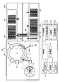
- FIG. 1 is a diagram schematically showing the configuration of the automatic analyzer according to the first embodiment of the present invention.
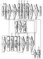
- FIG. 2 is a flowchart of rack transport by the rack transport mechanism.
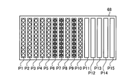
- FIG. 3 is a schematic diagram illustrating a configuration of the rack buffer unit according to the first embodiment of the present invention.
- FIG. 4 is a diagram illustrating a configuration example of rack information and position information stored in the rack information storage unit according to the first embodiment of the present invention.
- FIG. 5 is a flowchart of the analysis order determination in FIG.
- FIG. 6 is a diagram illustrating a configuration example of information when the dispensing order is determined by the determination unit based on the rack information of FIG. FIG.
- FIG. 7 is a diagram schematically showing the configuration of the automatic analyzer according to the first modification of the first embodiment of the present invention.
- FIG. 8 is a diagram schematically showing the configuration of the automatic analyzer according to the second embodiment of the present invention.
- FIG. 9 is a flowchart of rack transport by the rack transport mechanism according to Embodiment 2 of the present invention.
- FIG. 10 is a schematic diagram illustrating a configuration of a rack buffer unit according to the second embodiment.
- FIG. 11 is a diagram illustrating a configuration example of rack information and position information according to the second embodiment.
- FIG. 12 is a diagram illustrating a configuration example of the sample information according to the second embodiment.
- FIG. 13 is a diagram illustrating a flowchart for determining the analysis order in FIG. 9.
- FIG. 9 is a flowchart of rack transport by the rack transport mechanism according to Embodiment 2 of the present invention.
- FIG. 10 is a schematic diagram illustrating a configuration of a rack buffer unit according to the second embodiment.
- FIG. 14 is a diagram illustrating a configuration example of the blue rack group dispensing order determined based on the sample information (dispensing time in each module).
- FIG. 15 is a diagram illustrating a configuration example of the order of dispensing white rack groups determined based on sample information (dispensing time in each module).
- FIG. 16 is a diagram illustrating a configuration example of rack information including a rack dispensing order determined based on sample information (dispensing time in each module).
- an automatic analyzer according to an embodiment of the present invention will be described by taking an automatic analyzer that analyzes a liquid specimen such as blood as a sample.
- the drawings referred to in the following description are schematic. When the same object is shown in different drawings, the dimensions, scales, and the like may be different. Note that the present invention is not limited to the embodiments. In the description of the drawings, the same parts are denoted by the same reference numerals.
- FIG. 1 is a schematic diagram illustrating a configuration of an automatic analyzer 1 according to the first embodiment.
- the automatic analyzer 1 dispenses a sample and a reagent to be analyzed into a reaction vessel 5 respectively, and a measurement mechanism 40 that optically measures a reaction that occurs in the dispensed reaction vessel 5.
- the rack transport mechanism 60 that transports the rack 9 holding the sample container 9 a to the measurement mechanism 40, and the overall automatic analyzer 1 including the measurement mechanism 40 and the rack transport mechanism 60 are controlled, and the measurement results in the measurement mechanism 40 are displayed.
- a control mechanism 50 for performing analysis The automatic analyzer 1 automatically performs biochemical, immunological or genetic analysis of a plurality of specimens by cooperation of these mechanisms.
- the measurement mechanism 40 includes a reagent storage 2, a reaction table 4, a reagent dispensing device 6, a photometric device 11, a cleaning mechanism 12, a stirring device 13, and a sample dispensing device 20.
- the reagent container 2 includes a plurality of reagent containers 2 a that store reagents in the circumferential direction, and is rotated by driving means (not shown) to transport the reagent containers 2 a in the circumferential direction.
- Each of the plurality of reagent containers 2a is filled with a reagent corresponding to the inspection item, and an information recording medium (not shown) on which information such as the type, lot, and expiration date of the stored reagent is recorded is attached to the outer surface.
- a reading device (not shown) that reads the reagent information recorded on the information recording medium attached to the reagent container 2a and outputs the reagent information to the outer periphery of the reagent container 2 is installed.
- An openable / closable lid (not shown) is provided above the reagent cabinet 2 in order to suppress evaporation and denaturation of the reagent, and a thermostat bath (not shown) for reagent cooling is provided below the reagent cabinet 2. ) Is provided.
- the reagent dispensing device 6 includes an arm 6a that freely moves up and down in the vertical direction and rotates around a vertical line passing through the base end of the reagent dispensing device 6 as a central axis.
- a probe for aspirating and discharging the specimen is attached to the tip of the arm 6a.
- the reagent dispensing device 6 includes an intake / exhaust mechanism using an unillustrated intake / exhaust syringe or piezoelectric element.
- the reagent dispensing device 6 sucks the reagent from the reagent container 2a transferred to the predetermined position on the reagent storage 2 described above by the probe, rotates the arm 6a clockwise in the figure, and puts the reagent in the reaction container 5. Dispense and dispense.
- a cleaning tank 6c for cleaning the probe with cleaning water is installed on the probe trajectory.
- the reaction table 4 includes a plurality of reaction vessels 5 arranged in the circumferential direction, and is indicated by an arrow by a drive means (not shown) different from the drive means for driving the reagent storage 2.
- the reaction vessel 5 is moved in the circumferential direction by being rotated in the direction.
- An openable / closable lid (not shown) is provided above the reaction table 4, and a thermostat (not shown) for heating to a temperature that promotes the reaction between the specimen and the reagent is provided below the reaction table 4.
- the reaction vessel 5 is an optically transparent material that transmits 80% or more of the light contained in the analysis light (340 to 800 nm) emitted from the photometric device 11, such as glass containing heat-resistant glass, cyclic olefin, polystyrene, etc. It is a container called a cuvette formed into a square cylinder shape.
- the photometric device 11 is an optical system for analyzing an analysis light (340 to 800 nm) transmitted through a liquid sample in a reaction vessel 5 in which a reagent and a sample have reacted, and includes a light source, a spectroscopic unit, and a light receiving unit. ing.
- the analysis light emitted from the light source passes through the liquid sample in the reaction vessel 5 and is received by a light receiving unit provided at a position facing the spectroscopic unit.
- the cleaning device 12 performs cleaning by sucking and discharging the reaction solution in the reaction vessel 5 that has been measured by the photometry device 11 by using a nozzle, and injecting and sucking a cleaning solution such as detergent or cleaning water. Although the washed reaction vessel 5 is reused, the reaction vessel 5 may be discarded after completion of one measurement depending on the contents of inspection.
- the stirrer 13 stirs the dispensed specimen and reagent with a stir bar to homogenize the reaction.
- the specimen dispensing apparatus 20 includes an arm 20a that freely moves up and down in the vertical direction and rotates around a vertical line passing through the base end of the specimen.
- a probe for aspirating and discharging the specimen is attached to the tip of the arm 20a.
- the sample dispensing apparatus 20 includes an intake / exhaust mechanism using an intake / exhaust syringe or a piezoelectric element (not shown).
- the sample dispensing apparatus 20 sucks a sample from a sample container 9a transferred to a dispensing position by a rack transport mechanism 60, which will be described later, with a probe, and rotates the arm 20a counterclockwise in the figure to bring the reaction container 5 into the reaction container 5. Dispensing the sample.
- a cleaning tank 20c for cleaning the probe with cleaning water is installed on the probe trajectory.
- the rack transport mechanism 60 includes an emergency sample rack set unit 61, a rack set unit 62, a rack collection unit 63, a rack transfer unit 65, a reading device 66, a sample suction unit 67, and a rack buffer unit 68. .
- the rack 9 that holds a plurality of sample containers 9a for analysis is placed on the rack set unit 62.
- the user can place the rack 9 to be analyzed on the rack set unit 62 at any time, and the rack set unit 62 may be a unit on which a rack tray that holds a plurality of racks 9 is placed. May be.
- the rack 9 is replenished with the rack tray, all the racks 9 held in the rack tray are transferred to the rack buffer unit 68, and after the rack tray is emptied, the rack 9 is replaced with a rack tray that accommodates the rack 9. Refill rack 9. Even when the rack tray is used, the analysis is not interrupted because the unanalyzed rack 9 is placed in the rack buffer unit 68.
- the rack buffer unit 68 temporarily stores the unanalyzed rack 9 placed on the rack set unit 62.
- the information recording medium which recorded the sample information affixed on the sample container 9a is read.
- the information recording medium a bar code is usually used, but a two-dimensional code or an ID chip can also be used.
- the reading device 66 includes a color sensor that determines the color of the colored rack 9 and also determines the color of the rack 9 in addition to the rack information and the sample information.
- the rack 9 is colored red (emergency sample), blue (rapid sample), white (normal sample), etc., depending on the urgency of acquiring the analysis result of the sample held by the rack 9.
- the rack 9 holding the urgent sample is usually set in the urgent sample rack setting unit 61, and the sample aspirating unit 67 is transported from the urgent sample rack setting unit 61 to the sample aspirating unit 67 by the rack transfer unit 65 as soon as the sample aspirating unit 67 is empty, and analysis is performed. Is called.
- the rapid sample is for distinguishing a sample from a visit patient from an inpatient (ordinary sample) in a hospital, for example, and in order to quickly obtain the analysis result of the sample from the visit patient, It is possible to prioritize by changing the color.
- the rack collection unit 63 stores the rack 9 that has been analyzed.
- the rack 9 after the completion of the sample aspiration in the sample aspiration unit 67 is transported to the rack collection unit 63 by the rack transfer unit 65 only when the analysis is completed after the sample is dispensed and there is no error in the analysis result.
- the rack 9 is transported to the rack buffer unit 68 instead of the rack recovery unit 63 and waits until the analysis result is output from the rack buffer unit 68.
- the user can carry out the rack 9 conveyed to the rack collection unit 63 at any time.
- the rack transfer unit 65 includes a pull-in unit (not shown) that draws the rack 9 to be transferred to the rack transfer unit 65 side, and an extrusion unit (not shown) that pushes the rack from the rack transfer unit 65 side to the transfer destination. After moving to the position of the rack 9 to be moved, the rack 9 is pulled into the rack transfer unit 65 by a pull-in unit (not shown), and the rack information and sample information of the rack 9 are read by the reader 66 provided in the rack transfer unit 65. . The rack information and sample information read by the reading device 66 are stored together with the placement position on the rack buffer unit 68 by the rack information storage unit 22 to be described later. The rack transfer unit 65 also transfers the rack that holds the emergency sample placed on the emergency sample rack set unit 61 to the sample suction unit 67.
- the control mechanism 50 includes a control unit 15, an input unit 16, an output unit 17, an analysis unit 18, a storage unit 19, and a rack control unit 21.
- the control unit 15 is connected to each unit included in the measurement mechanism 40, the rack transport mechanism 60, and the control mechanism 50.
- a microcomputer or the like is used as the control unit 15.
- the control unit 15 performs predetermined input / output control on information input / output to / from each of these components, and performs predetermined information processing on the information.
- the control unit 15 controls the operation of each unit of the automatic analyzer 1, and based on the information read from the information recording medium, the automatic analyzer is configured to stop the analysis work when the expiration date of the reagent is out of the installation range. Control 1 or issue a warning to the operator.
- the input unit 16 is configured by using a keyboard, a mouse, and the like, and acquires various information necessary for analyzing the sample, instruction information for the analysis operation, and the like from the outside.
- the output unit 17 is configured using a printer, a communication mechanism, and the like, and outputs various information including the analysis result of the sample to notify the user.
- the analysis unit 18 calculates absorbance and the like based on the measurement result acquired from the photometric device 11 and performs component analysis of the specimen.
- the storage unit 19 is configured using a hard disk that magnetically stores information and a memory that loads various programs related to the process from the hard disk and electrically stores them when the automatic analyzer 1 executes the process. Various information including the analysis result of the specimen is stored.
- the storage unit 19 may include an auxiliary storage device that can read information stored in a storage medium such as a CD-ROM, a DVD-ROM, or a PC card.
- the rack control unit 21 controls the transfer of the rack 9 by the rack transfer unit 65.
- the rack control unit 21 includes a rack information storage unit 22, a determination unit 23, and a transfer control unit 24.
- the rack information storage unit 22 stores the rack information and sample information read by the reading device 66 together with the placement position on the rack buffer unit 68 of the rack 9.
- the rack information includes information on the rack color and the sample type to be accommodated.
- the sample information includes sample container information and sample ID.
- the determination unit 23 determines the analysis order based on the rack information and the sample information.
- the transfer control unit 24 controls the rack transfer unit 65 to move the rack 9 from the rack set unit 62 to the rack buffer unit 68, from the rack buffer unit 68 to the sample suction unit 67, and from the sample suction unit 67 to the rack buffer unit. 68 to the rack recovery unit 63 from the rack buffer unit 68. Further, the transfer control unit 24 controls the rack 9 placed on the rack buffer unit 68 to be transferred to the sample suction unit 67 in the analysis order determined by the determination unit 23.
- the sample held in the rack 9 transferred to the sample suction unit 67 by the rack transfer unit 65 with respect to the plurality of reaction containers 5 sequentially transferred in a row.
- the specimen in the container 9a is dispensed by the specimen dispensing apparatus 20, the reagent dispensing apparatus 6 dispenses the reagent in the reagent container 2a, and the photometric apparatus 11 reacts the specimen and the reagent.
- the spectral intensity measurement is performed, and the analysis unit 18 analyzes the measurement result, so that the component analysis of the specimen is automatically performed. Further, after the measurement by the photometric device 11 is completed by the cleaning mechanism 12, the reaction container 5 is cleaned while being transported, so that a series of analysis operations are continuously repeated.
- FIG. 2 is a flowchart of rack transport by the rack transport mechanism 60.
- FIG. 3 is a schematic diagram illustrating a configuration of the rack buffer unit 68 according to the first embodiment.
- FIG. 4 is a diagram illustrating a configuration example of rack information and position information stored in the rack information storage unit 22.
- FIG. 5 is a flowchart of the analysis order determination in FIG.
- FIG. 6 is a diagram illustrating a configuration example of rack information including a dispensing order determined based on the rack information of FIG.
- the rack 9 holding the sample container 9a containing the sample to be analyzed is set in the rack setting unit 62 (step S101).
- the rack 9 that accommodates the emergency sample is set in the emergency sample rack setting unit 61.
- the transfer control unit 24 determines whether or not the rack 9 is set in the emergency sample rack setting unit 61 (step S102). When the rack 9 is not set in the emergency sample rack setting unit 61 (No in step S102), the transfer control unit 24 extracts the number of racks 9 placed in the rack buffer unit 68 from the rack information storage unit 22. It is determined whether or not the number is less than the set number (step S103).
- step S104 When the number of racks 9 placed on the rack buffer unit 68 is equal to or less than the set number (Yes in step S103), the rack 9 of the rack set unit 62 is transferred to the rack transfer unit 65 under the control of the transfer control unit 24. Move (step S104).
- the reading device 66 reads the rack information and the sample information from the rack 9 drawn for transfer into the rack transfer unit 65 and the information storage medium attached to the sample container 9a held by the rack 9 (step S105). After acquiring the rack information and the sample information, the transfer control unit 24 controls the rack transfer unit 65 to transfer the rack 9 to the rack buffer unit 68 (step S106).
- the transfer control unit 24 acquires the information from the host computer together with the analysis item information of the sample when the sample type and sample container information stored from the information storage medium attached to the rack 9 and the sample container 9a cannot be acquired. To do.
- the rack information storage unit 22 stores the acquired rack information and sample information together with the placed position information (step S107).
- the transfer control unit 24 determines whether or not the rack 9 is present in the rack set unit 62 (step S108). When the rack 9 is present in the rack set unit 62 (step S108, Yes), step S102 and subsequent steps are repeated.
- the transfer control unit 24 determines whether the rack 9 containing the emergency sample can be transferred to the sample suction unit 67. It is determined whether or not the sample aspirating unit 67 has the rack 9 (step S113). If the sample aspirating unit 67 has the rack 9 (step S113, Yes), the sample aspirating unit is made to wait until it is empty. If the sample aspirating unit 67 does not have the rack 9 (step S113, No), the transfer control unit 24 Under the control, the rack 9 accommodating the urgent sample is moved to the rack transfer unit 65 (step S114).
- the emergency sample is stored.
- the rack 9 to be moved is transferred to the sample suction unit 67 by the rack transfer unit 65 (step S116), and the sample in the sample container 9a is dispensed by the sample dispensing device 20 (step S117).
- the transfer control unit 24 confirms whether or not the dispensing of all the analysis items of the urgent sample has been completed (step S118), and when the dispensing of all the analysis items of the urgent sample has been completed (step S118, Yes),
- the rack transfer unit 65 transports the rack 9 to the rack buffer unit 68 (step S119), and waits until an analysis result is obtained.
- step S118 the dispensing is continued for all the samples.
- the rack transport unit 21 transports the rack 9 to the rack buffer unit 68 (step S119)
- the rack transport unit 21 confirms whether or not the analysis is completed for the waiting rack 9 placed on the rack buffer unit 68 (step S120). If it has been completed (step S120, Yes), it is determined whether reexamination is necessary (step S121). If re-examination is necessary (step S121, Yes), the analysis order is determined again in step S110, and step S111 and subsequent steps are repeated.
- the rack 9 determined not to be reinspected is moved to the rack collection unit 63 by controlling the rack transfer unit 65 (Step S122). If no rack has been analyzed in the rack buffer unit 68 (step S120, No), the process is repeated from step S111 in order to continue dispensing in the analysis order determined in the previous step S110.
- Step S110 When the number of racks 9 placed in the rack buffer unit 68 reaches the set number by repeating Step S102 to Step S108 (No in Step S103), rack information and sample information stored in the rack information storage unit 22 Based on the above, the dispensing order of the racks 9 is determined (step S110).
- FIG. 3 is a schematic diagram illustrating a configuration of the rack buffer unit 68 according to the first embodiment.
- the rack buffer unit 68 can place a plurality of racks 9, and the placement locations of the racks 9 are, for example, P1, P2,.
- the timing for determining the analysis order of the racks 9 is set when the number of racks 9 placed on the rack buffer unit 68 reaches a predetermined value.
- the predetermined value is set to 10
- the dispensing order is determined.
- FIG. 4 is a diagram illustrating a configuration example of rack information and position information stored in the rack information storage unit 22.
- the rack information 501 includes a rack reception position, rack number, rack color, sample type, initial inspection (unanalyzed), or re-inspection for the rack 9 currently placed in the rack buffer unit 68. Necessity or the like is stored. For example, in the rack information 501, a rack 9 having a rack number 1001, a rack color of white, and a sample type of blood for the first test (unanalyzed) is placed at the rack reception position P1. The rack colors white, blue, and red are for distinguishing normal specimens (hospital patients), rapid specimens (visit patients), and emergency specimens. The urgent sample is usually placed in the urgent sample rack set unit 61.
- the rack buffer is placed on the rack set unit 62. Since the analysis order is determined by the unit 68, it is possible to carry out analysis by moving up the analysis order. Examples of the sample type include blood, urine, and the like, but when the specimen dispensing apparatus 20 employs a probe that continuously dispenses, such as a metal probe, the sample type is changed for the purpose of preventing carryover. Each time it is controlled to perform special cleaning in addition to normal cleaning. Therefore, by controlling so that the same sample type is continuously analyzed, the number of special cleaning operations can be reduced, whereby the total analysis time can be shortened and the cost for cleaning can be suppressed.
- the blank (-) in the re-inspection indicates the unanalyzed rack 9, the rack 9 that needs to be re-analyzed, and the standby that indicates the rack 9 waiting for the analysis result. Assume that the rack 9 determined to be re-inspected is preferentially analyzed.
- FIG. 5 is a diagram showing a flowchart for determining the analysis order in FIG.
- the determination unit 23 first classifies racks by rack color based on the rack information table 501 stored in the rack information storage unit 22 (step S201).
- the rack colors are analyzed in the order of red ⁇ blue ⁇ white, and the racks of each color are classified. Thereafter, in the rack group of each color, re-inspection and unanalyzed racks are classified (step S202), and finally classification by sample type is performed (step S203), and the determination unit 23 determines the analysis order (step S202).
- FIG. 6 is a configuration example of information when the dispensing order is determined by the determination unit 23 based on the rack information 501 of FIG. As shown in FIG.
- the red rack (rack number 3001) at the rack receiving position P10 is in the analysis order 1, and then the order of the blue rack group (receiving positions P6, P7, P9) is determined.
- the rack at the receiving position P9 (rack number 1017) is waiting for reinspection and is not incorporated into the analysis until it is determined whether reinspection is necessary.
- the blue racks at the reception positions P6 and P7 are unanalyzed racks whose sample type is blood and have no superiority or inferiority, and the analysis order is reception order (P6 is 2, P7 is 3).
- the order of the white rack group (reception positions P1, P2, P3, P4, P5, and P8) is the rack at the reception position P5 (rack number 1009) that requires re-inspection, and the reception position waiting for re-inspection.
- the order is determined by the receiving positions P1, P2, P3, and P8 excluding the rack of P4 (rack number 1007).
- the analysis order is determined by the sample type, the immediately preceding sample type (rack number 1009) of the analysis order 4 is blood, and since special cleaning is omitted, the blood sample rack is preferentially analyzed.
- the racks of the sample type blood are the reception positions P1, P3, and P8. Analysis is performed in the order of reception (P1 is 5, P3 is 6, P8 is 7), and finally the rack of the reception position P2 where the sample type is urine ( The rack number 1003) is analyzed.
- the dispensing order determination process shown in FIG. 5 is merely an example, and although each determination item (rack color, unanalyzed or re-inspected, sample type) does not change, the priority order can be changed according to the usage status of the user. .
- a rack 9 loaded with standard samples for calibration, accuracy control, etc. is also mounted on the rack buffer unit 68. However, like the rack 9 waiting for re-inspection, the rack buffer unit 68 is placed on standby and required. In this case, it is possible to transfer the sample to the sample aspirating unit 67 with priority.
- the transfer control unit 24 After determining the analysis order as described above (step S110), in order to transport the rack 9 to the sample suction unit 67 from the earlier analysis order, the transfer control unit 24 sets the rack 9 to the sample suction unit 67. It is confirmed whether or not there is (step S111). When the sample aspirating unit 67 does not have the rack 9 (No at Step S111), the transfer control unit 24 moves the rack 9 placed on the rack buffer unit 68 to the sample aspirating unit in the analysis order determined by the determining unit 23. Control to transfer. Under the control of the transfer control unit 24, the rack 9 in the analysis order 1 of the rack information 502 is transferred to the sample aspirating unit 67 by the rack transfer unit 65 (step S112), and the sample dispensing is performed by the sample dispensing device 20. (Step S117). If the sample aspirating unit 67 has the rack 9 (step S111, Yes), it waits until the rack of the sample aspirating unit 67 is transported.
- step S118 the transfer control unit 24 confirms whether dispensing of all the samples accommodated in the rack 9 has been completed. If yes (step S118, Yes), the rack 9 is transported to the rack buffer unit 68 (step S119), and waits until an analysis result is obtained. If not completed (No at step S118), the dispensing is continued for all the samples. After the rack 9 is transported to the rack buffer unit 68 (step S119), it is confirmed whether the analysis is completed for the rack 9 on standby placed on the rack buffer unit 68 (step S120). (Step S120, Yes), it is determined whether reexamination is necessary (Step S121).
- step S121, Yes If re-inspection is necessary (step S121, Yes), step S110 and subsequent steps are repeated again. If re-inspection is not necessary (step S121, No), the rack 9 that has determined that re-inspection is unnecessary is stored in the rack recovery unit. After moving to 63 (step S122), step S102 and subsequent steps are repeated. If there is no analysis-completed rack 9 in the rack buffer unit 68 (step S120, No), the process is repeated from step S111 in order to continue dispensing in the analysis order determined in the previous step S110.
- Step S109 if there is a rack 9 in the rack buffer unit 68 (step S109, Yes), the analysis order determination process of step S110 is performed on the rack 9 placed on the rack buffer unit 68, Analysis is performed in the determined order (steps S111 to S122 are repeated). If there is no rack 9 in the rack buffer unit 68 (No at Step S109), the analysis is completed.
- the rack 9 having a low priority is continuously placed in the rack buffer unit 68.
- the racks 9 that have been limited and have exceeded the time limit may be preferentially analyzed regardless of the analysis order.
- an automatic analyzer 1A in which the rack transport mechanism 60A includes a retest rack buffer unit 69 is illustrated (see FIG. 7).
- the waiting time of the analysis result of the rack 9 becomes long, the number of the waiting racks 9 placed on the rack buffer unit 68 increases, and the number of unanalyzed racks 9 placed on the rack buffer unit 68 is small.
- the standby time for the analysis result is increased by installing the retest rack buffer unit 69 as in the automatic analyzer 1A shown in FIG.
- the number of unanalyzed racks 9 placed on the rack buffer unit 68 can be set to a predetermined value or more, it is possible to maintain the effect of improving the analysis efficiency by changing the analysis order.
- the rack 9 is classified based on the analysis priority of the rack 9 according to the color of the rack 9, but the priority is magnetically determined by the location of the magnet attached to the bottom of the rack 9.
- the priority order may be optically determined by making a hole in the rack 9 and sorting by the position (physical shape) of the hole.
- the second embodiment relates to a rack transport method in a multifunction machine to which different analysis modules are connected.
- an automatic analyzer having different analysis modules, when an analysis item of a sample stored in the rack 9 is biased in one of the analysis modules (for example, a rack for performing analysis using only one analysis module follows, and then the other If there is a rack in which analysis is performed using only the analysis module of FIG. 2), the analysis is delayed in each analysis module, and the analysis efficiency may be reduced.
- the automatic analyzer 1B according to the second embodiment can determine the analysis order from the analysis item information of each rack 9 so that the operation status of each analysis module is the same. Adjustments can be made to reduce processing time.
- FIG. 8 is a diagram schematically showing the configuration of the automatic analyzer 1B according to Embodiment 2 of the present invention.
- the automatic analyzer 1B is a multifunction machine in which the biochemical analysis module 41 and the immunological analysis module 42 are connected, but this is merely an example.
- the biochemical analysis module 41 is substantially the same as the measurement mechanism 40 of the automatic analyzer according to the first embodiment, except that the reagent storages 2 and 3, the reagent dispensing devices 6 and 7, and the cleaning tanks 6 c and 7 c are each two. The configuration is provided.
- the immunological analysis module 42 includes an immune reaction table 31, a BF table 32, reagent tables 33 and 34, reagent dispensing devices 35 and 36, an enzyme reaction table 37, a photometric device 38, and a sample dispensing device 39. And reaction vessel transfer sections 55 and 56, washing tanks 35c and 36c, and a chip loading unit 57.
- the reagent tables 33 and 34 each store a plurality of reagent containers, and each reagent container is a reagent used for analysis of immunological analysis items, and is specific to the antigen or antibody in the sample to be analyzed.
- a substrate solution containing a reagent containing magnetic particles solid-phased with a reaction substance to be bound, a labeling substance (for example, an enzyme) that specifically binds to an antigen or antibody bound to the magnetic particle, and a substrate that emits light by an enzymatic reaction with the labeling substance Is housed.
- the immune reaction table 31 has a reaction line for reacting the specimen with a predetermined reagent in the reaction vessel 5a, and includes an outer peripheral line for the first reaction between the specimen and the magnetic particle reagent, and the specimen and the labeling reagent. It has two reaction lines, an inner peripheral line for the second reaction. Each reaction line is formed with a plurality of reaction container accommodating portions for accommodating the reaction containers 5a.
- the immune reaction table 31 is rotatable in the direction of the arrow in FIG. 8 with a vertical line passing through the center of the immune reaction table 31 as a rotation axis, and is a reaction container housed in a reaction container housing portion (not shown) of the immune reaction table 31. 5a is transferred to the specimen discharge position C or the like at a predetermined timing.
- the BF table 32 performs a BF cleaning process for performing a BF (bound-free) separation that separates unreacted substances in the specimen or reagent by sucking and discharging a predetermined cleaning liquid.
- the BF table 32 is rotatable in the direction of the arrow in FIG. 8 with a vertical line passing through the center of the BF table 32 as a rotation axis, and transfers the reaction vessel 5a disposed on the BF table 32 to a predetermined position at a predetermined timing.
- the BF table 32 includes a magnetism collecting mechanism that collects magnetic particles necessary for BF separation, a BF washing unit having a BF washing probe that performs BF separation by discharging and sucking BF liquid into the reaction vessel, and magnetism collecting. And a stirring mechanism for dispersing the magnetic particles.
- the enzyme reaction table 37 is a reaction line for performing an enzyme reaction process in which the substrate in the substrate solution injected into the reaction vessel 5a can emit light.
- the enzyme reaction table 37 is formed with a reaction container housing portion for housing the reaction container 5a in the circumferential direction.
- the enzyme reaction table 37 is rotatable in the direction of the arrow in FIG. 8 with a vertical line passing through the center of the enzyme reaction table 37 as a rotation axis, and the reaction vessel 5a disposed on the enzyme reaction table 37 is moved to a predetermined position at a predetermined timing. Transport to.
- the reaction container transfer parts 55 and 56 freely move up and down in the vertical direction and rotate around the vertical line passing through the base end part of the reaction container transfer parts 55 and 56 as a predetermined timing for the reaction container 5a containing the specimen and a predetermined reagent.
- an immune reaction table 31, a BF table 32, an enzyme reaction table 37, a photometric device 38, an arm for transferring to a predetermined position of a reaction container supply unit and a reaction container disposal unit (not shown) are provided.
- the sample dispensing device 39 dispenses the sample in the sample container 9a transported to the sample suction position A or B by the rack transport mechanism 60B to the reaction container 5a transported to the sample discharge position C on the immune reaction table 31. To do.
- the sample dispensing device 39 has a disposable tip for aspirating and discharging a sample attached to the tip of the probe, and freely moves up and down in the vertical direction and rotates around a vertical line passing through its base end as a central axis. .
- the sample dispensing device 39 includes an intake / exhaust mechanism using an intake / exhaust syringe or a piezoelectric element (not shown).
- the chip loading unit 57 has a chip case in which a plurality of chips are aligned, and a disposable chip is supplied from this case.
- This disposable chip is a disposable sample chip that is attached to the tip of the probe of the sample dispensing device 39 and is exchanged for each sample dispensing in order to prevent carryover during measurement of immunological analysis items. Further, at the chip mounting position G of the chip loading unit 57, in addition to mounting the disposable chip, the disposable chip is removed and a disposal box for used disposable chips is provided.
- the rack transport mechanism 60B has the same configuration as the rack transport mechanism 60 of the first embodiment, except that the transport lanes 69a, 69b, and 69c are provided.
- the rack transfer unit 65 controls the rack 9 from the rack set unit 62 to the rack buffer unit 68, from the rack buffer unit 68 to the transfer lane 69a or 69b, and from the transfer lane 69c to the rack buffer unit under the control of the transfer control unit 24B. 68 to the rack recovery unit 63 from the rack buffer unit 68.
- the rack 9 transferred to the transfer lane 69a by the rack transfer unit 65 is transferred on the transfer lane 69a by a transfer mechanism (not shown), and is aspirated by the sample dispensing device 20 of the biochemical analysis module 41 at the sample aspiration position E. Is discharged into the reaction vessel 5 on the reaction table 4. Further, the sample transported on the transport lane 69 a by a transport mechanism (not shown) and sucked by the sample dispensing device 39 of the immunological analysis module 42 at the sample suction position B is discharged to the reaction container 5 a on the immune reaction table 31. .
- the rack 9 is pushed out from the transfer lane 69a to the transfer lane 69c by an unillustrated push-out mechanism, and is transported on the transfer lane 69c by the unillustrated transfer mechanism to transfer the rack. It is transferred to the rack buffer unit 68 by the unit 65.
- the rack 9 may be first transported to the sample suction position B according to the operating status of each analysis module. In addition, some racks 9 perform analysis using only one of the analysis modules. In such a case, the rack 9 is transported to one of the sample aspirating positions, and after dispensing, the rack is moved by an unillustrated push-out mechanism. 9 is pushed out to the transport lane 69 c and transported on the transport lane 69 c by a transport mechanism (not shown), and then the rack 9 is transported to the rack buffer unit 68 by the rack transport unit 65.
- the rack 9 different from the rack 9 transferred to the transfer lane 69b by the rack transfer unit 65 is transferred on the transfer lane 69b by a transfer mechanism (not shown), and the biochemical analysis module 41 at the sample suction position D.
- the sample aspirated by the sample dispensing apparatus 20 is discharged into the reaction container 5 on the reaction table 4. Further, the sample transported on the transport lane 69b by a transport mechanism (not shown) and sucked by the sample dispensing device 39 of the immunological analysis module 42 at the sample suction position A is discharged to the reaction container 5a on the immune reaction table 31. .
- the rack 9 is pushed out from the transfer lane 69b to the transfer lane 69c by the push-out mechanism (not shown), and is transferred on the transfer lane 69c by the transfer mechanism (not shown).
- the rack is transferred to the rack buffer unit 68 by the rack transfer unit 65.
- the rack 9 may be first transported to the sample suction position A according to the operating status of each analysis module. In addition, some racks 9 perform analysis using only one of the analysis modules. In such a case, the rack 9 is transported to one of the sample aspirating positions, and after dispensing, the rack is moved by an unillustrated push-out mechanism. 9 is pushed out to the transport lane 69 c and transported on the transport lane 69 c by a transport mechanism (not shown), and the rack 9 is transported to the rack buffer section 68 by the rack transport section 65.
- the control mechanism 50B is different from the control mechanism 50 of the first embodiment in that the rack control unit 21B includes the calculation unit 25. Based on the analysis item information extracted from the host or the like, the calculation unit 25 accumulates the dispensing time for each analysis module for each rack 9.
- the rack information storage unit 22B stores analysis item information and the dispensing time for each analysis module calculated by the calculation unit 25 in addition to rack information, sample information, and rack position information.
- the determining unit 23B determines the rack dispensing order based on the rack color and the dispensing time of each rack 9 stored in the rack information storage unit 22B in units of analysis modules.
- FIG. 9 is a flowchart of rack transport by the rack transport mechanism 60B.
- FIG. 10 is a schematic diagram illustrating a configuration of the rack buffer unit 68 according to the second embodiment.
- FIG. 11 is a diagram illustrating a configuration example of rack information and position information.
- FIG. 12 is a diagram illustrating a configuration example of sample information.
- FIG. 13 is a diagram illustrating a flowchart for determining the analysis order in FIG. 9.
- FIG. 14 is a diagram showing a configuration example of the dispensing order for the blue rack group determined based on the sample information (dispensing time in each module).
- FIG. 10 is a schematic diagram illustrating a configuration of the rack buffer unit 68 according to the second embodiment.
- FIG. 11 is a diagram illustrating a configuration example of rack information and position information.
- FIG. 12 is a diagram illustrating a configuration example of sample information.
- FIG. 13 is a diagram illustrating a flowchart for determining the analysis order in FIG. 9.
- FIG. 15 is a diagram illustrating a configuration example of the dispensing order for the white rack group determined based on the sample information (dispensing time in each module).
- FIG. 16 is a diagram illustrating a configuration example of rack information including a rack dispensing order determined based on sample information (dispensing time in each module).
- the rack transport according to the second embodiment is performed until the rack information and the sample information are read by the reading device 66 when transported from the rack set section 62 to the rack buffer section 68 by the rack transport section 65 (see FIG. 9, step S305).
- the host computer (not shown) connected to the storage unit 19 of the automatic analyzer 1B or the automatic analyzer 1B based on the read sample information is the same as the rack transport in the first embodiment.
- the calculation unit 25 integrates the dispensing time for each analysis module for each rack 9 based on the extracted analysis item information (step S307).
- the rack 9 from which the rack information and the sample information are read is transferred to the rack buffer unit 68 by the rack transfer unit 65 under the control of the transfer control unit 24B (step S308).
- the rack information storage unit 22B stores the dispensing time in units of analysis modules for each rack 9 calculated by the calculation unit 25, along with the rack information, sample information, analysis item information, and position information (step S309).
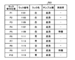
- the rack information read by the reading device 66 is stored in the rack information storage unit 22B as a rack information table 503 as shown in FIG. Is remembered.
- the reading device 66 also reads the sample information of the sample container 9a accommodated in the rack 9, and the sample information is stored in the rack information storage unit 22B as a sample information table 504 as shown in FIG. 12 together with the extracted analysis item information. Is done.
- the sample information table 504 is configured for each rack, and stores, for example, a rack number, a sample container position, a sample number, and an analysis item.
- the specimen information table 504 also stores the biochemical dispensing time and the immune dispensing time calculated by the calculation unit 25.
- the biochemical dispensing time and the immune dispensing time are calculated by calculating the number of biochemical items and the number of immune items based on the analysis items, and integrating the dispensing time required for one dispensing in each analysis module.
- the specimen information table 504 also stores the total time of the biochemical dispensing time and the immune dispensing time of the specimen stored in the rack (rack number 1101).
- steps S302 to S310 are repeated until the number of racks in the rack buffer unit 68 reaches the set number (step S303, Yes).
- the determining unit 23B determines the analysis order of the racks 9 placed on the rack buffer unit 68 (Step S312). As shown in FIG. 13, in determining the analysis order of the racks 9 by the determination unit 23B, racks are first classified by rack color based on the rack information stored in the rack information storage unit 22B (step S401). The rack colors are analyzed in the order of red ⁇ blue ⁇ white, and the racks of each color are classified.
- the racks 9 are ranked based on the dispensing time of each rack 9 in units of analysis modules (step S402), and the analysis order is determined (step S403).
- the analysis order may be determined according to whether it is a re-inspection rack or an unanalyzed rack as in the first embodiment, or the analysis order may be changed depending on the sample type.
- the rack information storage unit 22B includes the rack information.
- the rack information table 505 and 506 are stored as rack information tables 505 and 506 to which biochemical dispensing time and immune dispensing time (total) are added.
- the rack information table 505 of the blue rack group is for three racks except for the rack number 1117 waiting for reexamination, and is ranked according to the length of biochemical dispensing time and immune dispensing time.
- the operation time of each analysis module can be made the same, so the dispensing time in each analysis module is long, or Change the analysis order to dispense alternately from the shortest.
- the biochemical dispensing time is in the order of rack numbers 1111 (500 seconds), 1113 (400 seconds), 1119 (100 seconds), and the length of immune dispensing time is rack numbers 1119 (400 seconds), 1113. Since (40 seconds) and 1111 (0 seconds), the analysis is performed alternately from the modules having the dispensing length rank of 1.
- the analysis order is rack numbers 1111, 1119, 1113.
- the time for transporting and dispensing the rack number 1111 as the analysis order 1 to the biochemical analysis module is 500 seconds, and the time for transporting the rack number 1119 of the dispensing order 2 to the immunoassay module and dispensing is approximately 400 seconds. It becomes the same time, and each analysis module is in the same operating condition.
- the rack information table 506 of the white rack group is for five racks except for the rack number 1109 waiting for re-examination. Like the blue rack group, the rack information table 506 is ranked according to the length of the biochemical dispensing time and the immune dispensing time. Is done. Ranking from the longest biochemical dispensing time, the rack numbers are 1101 (400 seconds), 1103 (350 seconds), 1107 (200 seconds), 1105 (150 seconds), 1115 (80 seconds). From longest time, rack numbers 1115 (400 seconds), 1105 (360 seconds), 1107 (300 seconds), 1103 (200 seconds), 1101 (180 seconds).
- the order of analysis of the white rack group is from that of biochemical dispensing time length rank 1 to immune dispensing time length rank 1, biochemical rank 2, so that the operating status of each analysis module is comparable.
- the analysis order is alternately performed with the immunity order 2...
- the analysis order is rack number 1101 (analysis order 1), 1115 (analysis order 2), 1103 (analysis order 3), 1105 (analysis order 4), 1107 ( The order of analysis is 5).
- FIG. 16 shows a rack information table 507 to which the dispensing order and transport lanes of all racks 9 determined by the determination unit 23B are added. Since the blue rack group is given priority and the white rack group is analyzed thereafter, rack numbers 1111 (analysis order 1), 1119 (analysis order 2), 1113 (analysis order 3), 1101 (analysis order 4), 1115 (analysis order 5), 1103 (analysis order 6), 1105 (analysis order 7), and 1107 (analysis order 8).
- the transportation lane has an odd number 69a in dispensing order and an even number 69b (or vice versa).
- the racks 9 in which the analysis order is determined are all unanalyzed racks 9 and the dispensing time in each analysis module is relatively long, so that the racks 9 are alternately transported in the transport lanes 69a and 69b. However, in re-inspection racks, dispensing may be completed in a short time. In such a case, the determination unit 23B also selects the transport lane so as to determine the analysis order so that the operation statuses of the analysis modules are approximately the same.
- the analysis order shown in the rack information table 507 is a sequential dispensing order in which the analysis order of the blue rack group and the analysis order of the white rack group are kept as they are. The order may be determined.
- step S313 and subsequent steps are performed in order to perform dispensing in the determined analysis order.
- Step S313 and subsequent steps are the same as step S111 and subsequent steps in the flowchart shown in FIG.
- the automatic analyzer and the rack transport method of the present invention are useful in an automatic analyzer that wants to change the order of analysis according to the sample, and in particular, an efficient analysis with an automatic analyzer having a plurality of analysis modules. Suitable for doing.
Landscapes
- Chemical & Material Sciences (AREA)
- Physics & Mathematics (AREA)
- Health & Medical Sciences (AREA)
- Life Sciences & Earth Sciences (AREA)
- Analytical Chemistry (AREA)
- Biochemistry (AREA)
- General Health & Medical Sciences (AREA)
- General Physics & Mathematics (AREA)
- Immunology (AREA)
- Pathology (AREA)
- Chemical Kinetics & Catalysis (AREA)
- Automatic Analysis And Handling Materials Therefor (AREA)
Abstract
ラックバッファー部(68)に載置される分析待ちのラック(9)のラック情報等に基づき、ラックの分析順を変更して分析効率を向上しうる自動分析装置(1)を提供する。この目的のために、自動分析装置(1)は、測定機構40に移送前のラック(9)を一時的に載置保管するラックバッファー部(68)を備え、ラック移送部(65)上に備えられる読取装置(66)により、ラック(9)と検体容器(9a)とに貼付された情報記憶媒体からラック情報と検体情報とを読み取り、該情報をラック情報記憶部(22)に位置情報と共に記憶し、該情報に基づき決定部(23)が分析順を決定して、移送制御部(24)が該分析順にラック(9)を検体吸引部(67)に移送するよう制御する。
Description
本発明は、分析前の複数の検体容器を搭載したラックの分析順を調整しうる自動分析装置ならびにラック搬送方法に関する。
検体と試薬とを反応させることによって検体の成分の分析を行う自動分析装置では、検体容器に収容されている検体を所定の反応容器へ分注し、その反応容器内で検査項目に応じた試薬と混合し、反応を生じさせている。このような検体の分注を迅速に行うため、自動分析装置には、複数の検体容器をまとめて搭載したラックを搬送するラック搬送機構が設けられている。
近年、分析結果が測定可能範囲を超える等の異常値を示した場合に、同一検体について再検査を行なうために、分注が終了後分析結果の待機用のラック待機部を設けて、再検査が必要な場合に該ラック待機部からラックを分析モジュールまで搬送する自動分析装置が開示されている(例えば、特許文献1および2を参照)。同様に、ラックをセットする荷載ラック部とラックの位置決め装置とラックを搬送する搬送装置とを備え、入力データと複数の試料処理の優先順位とに基づき、搬送装置によりラックを荷載ラック部から位置決め装置に搬送し、位置決め装置が診断モジュールで試験可能なように位置決めする分析装置が開示されている(例えば、特許文献3を参照)。さらに、生化学分析部と免疫分析部の2つの分析モジュールを備え、ラックに収容される検体の分析項目に応じて免疫分析部と生化学分析部とへの搬送を振り分ける振り分け部と、ラック待機部とを備えた分析装置が開示されている(例えば、特許文献4を参照)。
ところで、特許文献1および2に開示される分析装置では、分注済みのラックについて、再検査または搬出指示が出ていないラックをラック待機部に載置することができるので、分析終了し再検査指示が出されたラックについては即時に再分析可能であるが、これから分析を行うラックの分析順序を制御することはできず、緊急検体を除いて受け入れ順に分析が行われることになる。このため、緊急検体以外で早期に分析結果を知りたい検体がある場合には対応することができない。また、生化学分析、免疫学分析等、異なる分析モジュールを備える複合機においては、受付順にサンプルラックの分析を行うことになるため、サンプルラックに収容される検体の分析項目がどちらかの分析モジュールに偏っているラックが続く場合、他方の分析モジュールは待機状態となり、装置全体の分析効率が著しく低下してしまう。
また、特許文献3に開示される装置では、これから分注が行なわれるラックや、分注後の再検査要否未定で待機中のラックがすべて荷載ラック部に保管され、荷載ラック部に載置されるラックに対してプログラムされた優先順位に基づき分析順を決定する。したがって、複数の分析モジュールを備えた装置での稼動効率は優れるものの、ラックの搬入・搬出はすべて荷載ラック部で行なわれるため、誤ったラックの抜き取り防止のためにすべてのラックの分析が終了するまで荷載ラック部にアクセスできず、装置へのラックの搬入・搬出時は分析が中断されるという問題を有する。
さらに、特許文献4に開示される装置では、搬送先を振り分け、搬送予定の分析モジュールにおいて分注待ちとなる場合にはラック待機部に搬送することにより搬送レーンの渋滞を回避できるものの、未分析のラックの分析項目を考慮してラックの分析順を変更することはできないため、装置全体の分析効率を向上することはできない。
本発明は、上記に鑑みてなされたものであって、ラックバッファー部に載置された分析待ちのラックのラック情報、検体情報、分析項目等の情報に基づき、ラックの分析順を変更して装置全体の稼働状況を改善し、分析効率を向上する自動分析装置を提供することを目的とする。
上述した課題を解決し、目的を達成するために、本発明の自動分析装置は、検体と試薬とを反応させた反応物を含む液体検体を光学的に分析する分析モジュールを少なくとも1以上備える自動分析装置において、検体を収容する検体容器を複数保持しうるラックをセットするラックセット部と、分析が終了した検体容器を保持するラックを載置するラック回収部と、分析モジュールに移送前のラックを一時的に載置保管するラックバッファー部と、前記ラックセット部、前記ラック回収部、前記ラックバッファー部および検体吸引部間を移動してラックを搬送するラック移送部と、前記ラック移送部により移送される前記ラックおよび/または前記検体容器からラック情報と検体情報とを読み取る読取装置と、前記ラックバッファー部に載置されるすべてのラックのラック情報および検体情報に位置情報を付加して記憶するラック情報記憶部と、前記ラック情報記憶部に記憶されたラック情報および検体情報に基づき、前記ラックバッファー部に載置されるすべてのラックの分析順を決定する決定部と、前記ラックバッファー部に載置される前記ラックを、前記決定部が決定した分析順に前記分析モジュールの検体分注位置へ移送するよう前記ラック移送部を制御する移送制御部と、を備えることを特徴とする。
また、本発明の自動分析装置は、上記発明において、前記ラックは分析の優先順位に基づき区別され、前記読取装置は前記ラックの優先順位を判別し、前記決定部は、該判別した優先順位に基づき分析順を決定することを特徴とする。
前記ラックの優先順位は、前記ラックの色、前記ラックに貼付された磁気情報、前記ラックの物理的形状により判別されることを特徴とする。
また、本発明の自動分析装置は、上記発明において、前記決定部は、サンプル種類に基づき分析順を決定することを特徴とする。
また、本発明の自動分析装置は、上記発明において、検体と試薬とを反応させた反応物を含む液体検体を光学的に分析するための分析モジュールを2以上備え、前記ラック移送部は複数の搬送レーンを備え、前記決定部は前記ラックの分析順および移送する前記ラックの搬送レーンを決定することを特徴とする。
また、本発明の自動分析装置は、上記発明において、検体と試薬とを反応させた反応物を含む液体検体を光学的に分析するための異なる分析モジュールを備え、分析項目情報を抽出し、該分析項目情報に基づきラック毎に分析モジュール単位の分注時間を積算する算出部を備え、前記ラック情報記憶部は各検体の分析項目情報および前記算出部により算出された分析モジュール単位の分注時間を記憶し、前記決定部は、前記ラック情報記憶部が記憶する前記ラックの分析モジュール単位の分注時間に基づき、前記ラックの分注順を決定することを特徴とする。
また、本発明の自動分析装置は、上記発明において、前記ラックバッファー部は、再検査要否未定で待機中のラックも載置保管し、前記決定部は、未分析の検体容器を保持する前記ラックと、再検査を要する検体容器を保持する前記ラックとを含むすべてのラックについて分析順を決定することを特徴とする。
また、本発明の自動分析装置は、上記発明において、再検査要否未定で待機中のラックを載置保管する再検ラックバッファー部を備え、前記決定部は、未分析の検体容器を保持する前記ラックと、再検査を要する検体容器を保持する前記ラックとを含むすべてのラックについて1の分析順を決定することを特徴とする。
また、本発明の自動分析装置のラック搬送方法は、検体と試薬とを反応させた反応物を含む液体検体を光学的に分析する自動分析装置におけるラック搬送方法において、ラックセット部にセットされた分析前のラックをラック移送部によりラックバッファー部に搬送する第1搬送ステップと、第1搬送ステップでの搬送時に搬送する前記ラックのラック情報と検体情報とを読み取る読み取りステップと、前記ラックバッファー部に載置されるすべてのラックのラック情報および検体情報に位置情報を付加して記憶するラック情報記憶ステップと、前記ラック情報記憶ステップで記憶されたラック情報および検体情報に基づき前記ラックバッファー部に載置されるすべてのラックの分析順を決定する決定ステップと、前記ラックバッファー部に載置される前記ラックを、ラック移送部により前記決定ステップが決定した分析順に分析モジュールの検体分注位置に搬送する第2搬送ステップと、を含むことを特徴とする。
また、本発明の自動分析装置のラック搬送方法は、上記の発明において、前記ラックは分析の優先順位に基づき区別され、前記読み取りステップは前記ラックの優先順位を判別して、該判別した優先順位に基づき前記決定ステップで分析順を決定することを特徴とする。
また、本発明の自動分析装置のラック搬送方法は、上記の発明において、前記ラックの優先順位は、前記ラックの色、前記ラックに貼付された磁気情報、前記ラックの物理的形状により判別されることを特徴とする。
また、本発明の自動分析装置のラック搬送方法は、上記の発明において、サンプル種類に基づき分析順を決定することを特徴とする。
また、本発明の自動分析装置のラック搬送方法は、上記の発明において、検体と試薬とを反応させた反応物を含む液体検体を光学的に分析するための分析モジュールを2以上備え、前記ラック移送部は複数の搬送レーンを備え、前記決定ステップは前記ラックの分析順および移送する前記ラックの搬送レーンを決定することを特徴とする。
また、本発明の自動分析装置のラック搬送方法は、上記の発明において、検体と試薬とを反応させた反応物を含む液体検体を光学的に分析するための異なる分析モジュールを2以上備え、ホストコンピューターまたは記憶部から検体の分析項目情報を抽出する抽出ステップと、前記分析項目情報に基づきラック毎に分析モジュール単位の分注時間を積算する算出ステップとを含み、前記ラック情報記憶ステップは前記分析項目情報および前記算出ステップにより算出したラック毎の分析モジュール単位の分注時間を記憶し、前記決定ステップは、前記ラック情報記憶ステップが記憶するラック毎の分析モジュール単位の分注時間に基づき、前記ラックの分析順を決定することを特徴とする。
また、本発明の自動分析装置のラック搬送方法は、上記の発明において、前記ラックバッファー部は、分注終了後の再検査要否未定で待機中のラックも載置保管し、前記決定ステップは、未分析の検体容器を保持する前記ラックと、再検査を要する検体容器を保持する前記ラックとを含むすべてのラックについて分析順を決定することを特徴とする。
また、本発明の自動分析装置のラック搬送方法は、上記の発明において、分注終了後で再検査要否未定で待機中のラックを載置保管する再検ラックバッファー部を備え、前記決定ステップは、未分析の検体容器を保持する前記ラックと、再検査を要する検体容器を保持する前記ラックとを含むすべてのラックについて1の分析順を決定することを特徴とする。
本発明の自動分析装置ならびにラック搬送方法では、ラックバッファー部に載置される未分析のラックについて、ユーザーの指定する優先順位に基づき、ラック情報、検体情報、および分析項目情報を参照してラックの分析順を容易に変更でき、特に複数の分析モジュールを搭載する分析装置においては、分析効率を大幅に改善できるという効果を奏する。
以下、添付した図面を参照して、この発明の実施の形態にかかる自動分析装置について、血液などの液体検体をサンプルとして分析する自動分析装置を例に説明する。以下の説明で参照する図面は模式的なものであって、同じ物体を異なる図面で示す場合には、寸法や縮尺等が異なる場合もある。なお、この実施の形態によりこの発明が限定されるものではない。また、図面の記載において、同一部分には同一の符号を付している。
(実施の形態1)
図1は、実施の形態1にかかる自動分析装置1の構成を示す模式図である。図1に示すように、自動分析装置1は、分析対象である検体および試薬を反応容器5にそれぞれ分注し、分注した反応容器5内で生じる反応を光学的に測定する測定機構40と、検体容器9aを保持するラック9を測定機構40に搬送するラック搬送機構60と、測定機構40とラック搬送機構60とを含む自動分析装置1全体の制御を行うとともに測定機構40における測定結果の分析を行う制御機構50とを備える。自動分析装置1は、これらの機構が連携することによって複数の検体の生化学的、免疫学的あるいは遺伝学的な分析を自動的に行う。
図1は、実施の形態1にかかる自動分析装置1の構成を示す模式図である。図1に示すように、自動分析装置1は、分析対象である検体および試薬を反応容器5にそれぞれ分注し、分注した反応容器5内で生じる反応を光学的に測定する測定機構40と、検体容器9aを保持するラック9を測定機構40に搬送するラック搬送機構60と、測定機構40とラック搬送機構60とを含む自動分析装置1全体の制御を行うとともに測定機構40における測定結果の分析を行う制御機構50とを備える。自動分析装置1は、これらの機構が連携することによって複数の検体の生化学的、免疫学的あるいは遺伝学的な分析を自動的に行う。
測定機構40は、試薬庫2と、反応テーブル4と、試薬分注装置6と、測光装置11と、洗浄機構12と、攪拌装置13と、検体分注装置20とを備えている。
試薬庫2は、図1に示すように、試薬を収容する試薬容器2aが周方向に複数配置され、駆動手段(図示せず)により回転されて試薬容器2aを周方向に搬送する。複数の試薬容器2aは、それぞれ検査項目に応じた試薬が満たされ、外面には収容した試薬の種類、ロット及び有効期限等の情報を記録した情報記録媒体(図示せず)が貼付されている。ここで、試薬庫2の外周には、試薬容器2aに貼付した情報記録媒体に記録された試薬情報を読み取り、制御部へ出力する読取装置(図示せず)が設置されている。試薬庫2の上方には、試薬の蒸発や変性を抑制するため、開閉自在な蓋(図示せず)が設けられており、試薬庫2の下方には試薬冷却用の恒温槽(図示せず)が設けられている。
試薬分注装置6は、鉛直方向への昇降および自身の基端部を通過する鉛直線を中心軸とする回転を自在に行なうアーム6aを備える。このアーム6aの先端部には、検体の吸引および吐出を行なうプローブが取り付けられている。試薬分注装置6は、図示しない吸排シリンジまたは圧電素子を用いた吸排機構を備える。試薬分注装置6は、上述した試薬庫2上の所定位置に移送された試薬容器2aの中からプローブによって試薬を吸引し、アーム6aを図中時計回りに旋回させ、反応容器5に試薬を吐出して分注を行なう。また、プローブの回動軌跡上には、洗浄水によってプローブを洗浄する洗浄槽6cが設置される。
反応テーブル4は、図1に示すように、複数の反応容器5が周方向に沿って配列されており、試薬庫2を駆動する駆動手段とは異なる駆動手段(図示せず)によって矢印で示す方向に回転されて反応容器5を周方向に移動させる。反応テーブル4の上方には開閉自在な蓋(図示せず)が、下方には検体と試薬の反応を促進させる温度に加温するための恒温槽(図示せず)がそれぞれ設けられている。
反応容器5は、測光装置11から出射された分析光(340~800nm)に含まれる光の80%以上を透過する光学的に透明な素材、例えば、耐熱ガラスを含むガラス、環状オレフィンやポリスチレン等によって四角筒状に成形されたキュベットと呼ばれる容器である。
測光装置11は、試薬と検体とが反応した反応容器5内の液体試料に分析光(340~800nm)を透過させて分析するための光学系であり、光源、分光部及び受光部を有している。光源から出射された分析光は、反応容器5内の液体試料を透過し、分光部と対向する位置に設けた受光部によって受光される。
洗浄装置12は、ノズルによって測光装置11による測定が終了した反応容器5内の反応液を吸引して排出するとともに、洗剤や洗浄水等の洗浄液を注入および吸引することで洗浄を行なう。この洗浄した反応容器5は再利用されるが、検査内容によっては1回の測定終了後に反応容器5を廃棄してもよい。
攪拌装置13は、分注された検体と試薬とを攪拌棒によって攪拌し、反応を均一化させる。
検体分注装置20は、鉛直方向への昇降および自身の基端部を通過する鉛直線を中心軸とする回転を自在に行なうアーム20aを備える。このアーム20aの先端部には、検体の吸引および吐出を行なうプローブが取り付けられている。検体分注装置20は、図示しない吸排シリンジまたは圧電素子を用いた吸排機構を備える。検体分注装置20は、後述するラック搬送機構60により分注位置に移送された検体容器9aの中からプローブによって検体を吸引し、アーム20aを図中反時計回りに旋回させ、反応容器5に検体を吐出して分注を行なう。また、プローブの回動軌跡上には、洗浄水によってプローブを洗浄する洗浄槽20cが設置される。
ラック搬送機構60は、緊急検体ラックセット部61と、ラックセット部62と、ラック回収部63と、ラック移送部65と、読取装置66と、検体吸引部67と、ラックバッファー部68とを備える。
ラックセット部62には、分析を行う検体容器9aを複数保持するラック9を載置する。ユーザーは分析を行うラック9を随時ラックセット部62に載置することが可能であり、ラックセット部62は、複数のラック9を保持するラックトレイを載置するものでもよく、キャタピラ方式であってもよい。ラックトレイによってラック9を補充する場合は、ラックトレイに保持されるラック9がすべてラックバッファー部68に移送され、ラックトレイが空になった後、ラック9を収容するラックトレイと交換することによりラック9を補充する。ラックトレイを使用する場合でも、ラックバッファー部68に未分析のラック9が載置されているので、分析が中断することはない。
ラックバッファー部68は、ラックセット部62に載置された未分析のラック9を一時的に保管する。ラックバッファー部68に載置される未分析のラック9は、ラック移送部65によりラックセット部62から移送される際、読取装置66により、ラック9に貼付されるラック情報を記録した情報記録媒体と、検体容器9aに貼付される検体情報を記録した情報記録媒体とを読み込む。情報記録媒体としては、通常バーコードが使用されるが、二次元コードやIDチップなどの使用も可能である。さらに読取装置66は、着色されたラック9の色を判別するカラーセンサを備え、ラック情報および検体情報に加え、ラック9の色も判別する。ラック9は、ラック9が保持する検体の分析結果取得の緊急度により、赤(緊急検体)、青(迅速検体)、白(通常検体)等に着色されている。緊急検体を保持するラック9は、通常緊急検体ラックセット部61にセットされ、検体吸引部67が空き次第緊急検体ラックセット部61からラック移送部65により検体吸引部67に搬送され、分析が行われる。迅速検体は、例えば、病院などにおいて、来院患者からの検体を入院患者(通常検体)と区別するためのものであり、来院患者からの検体の分析結果を迅速に入手するために、ラック9の色を変えて優先順位付けを行なうことが可能である。
ラック回収部63は、分析が終了したラック9を保管する。検体吸引部67での検体吸引終了後のラック9は、検体分注後に分析が終了し、分析結果にエラーがない場合にのみラック移送部65によりラック回収部63に搬送される。分析結果が出ていない場合は、ラック9は、ラック回収部63でなく、ラックバッファー部68に搬送され、ラックバッファー部68で分析結果が出るまで待機する。ユーザーは、ラック回収部63に搬送されたラック9を随時搬出することができる。
ラック移送部65は、移送するラック9をラック移送部65側へ引き込む引き込み部(図示せず)と、ラック移送部65側から移送先にラックを押し出す押し出し部(図示せず)を備え、搬送するラック9の位置まで移動後、引き込み部(図示せず)によりラック9をラック移送部65に引き込み、前記ラック移送部65に備えられる読取装置66によりラック9のラック情報と検体情報とを読み込む。読取装置66により読み込んだラック情報と検体情報は、後述するラック情報記憶部22によりラックバッファー部68上の載置位置とともに記憶される。また、ラック移送部65は、緊急検体ラックセット部61に載置される緊急検体を保持するラックの検体吸引部67への移送も行なう。
つぎに、制御機構50について説明する。制御機構50は、制御部15と、入力部16と、出力部17と、分析部18と、記憶部19と、ラック制御部21とを備える。制御部15は、測定機構40、ラック搬送機構60および制御機構50が備える各部と接続される。これら各部の作動を制御するため、制御部15には、マイクロコンピュータ等が使用される。制御部15は、これらの各構成部位に入出力される情報について所定の入出力制御を行い、かつ、この情報に対して所定の情報処理を行う。制御部15は、自動分析装置1の各部の作動を制御すると共に、情報記録媒体から読み取った情報に基づき、試薬の有効期限等が設置範囲外の場合、分析作業を停止するように自動分析装置1を制御し、或いはオペレータに警告を発する。
入力部16は、キーボード、マウス等を用いて構成され、検体の分析に必要な諸情報や分析動作の指示情報等を外部から取得する。出力部17は、プリンタ、通信機構等を用いて構成され、検体の分析結果を含む諸情報を出力し、ユーザーに報知する。分析部18は、測光装置11から取得した測定結果に基づいて吸光度等を演算し、検体の成分分析等を行う。記憶部19は、情報を磁気的に記憶するハードディスクと、自動分析装置1が処理を実行する際にその処理にかかわる各種プログラムをハードディスクからロードして電気的に記憶するメモリとを用いて構成され、検体の分析結果等を含む諸情報を記憶する。記憶部19は、CD-ROM、DVD-ROM、PCカード等の記憶媒体に記憶された情報を読み取ることができる補助記憶装置を備えてもよい。
ラック制御部21は、ラック移送部65によるラック9の移送を制御する。ラック制御部21は、ラック情報記憶部22と、決定部23と、移送制御部24とを備える。ラック情報記憶部22は、読取装置66により読み取られたラック情報と検体情報とを、ラック9のラックバッファー部68上の載置位置とともに記憶する。ラック情報には、ラックIDの他、ラック色、収容するサンプル種の情報が含まれる。検体情報には、検体容器情報、検体IDが含まれる。決定部23は、前記ラック情報および前記検体情報に基づき分析順を決定する。移送制御部24は、ラック移送部65を制御することにより、ラック9を、ラックセット部62からラックバッファー部68へ、ラックバッファー部68から検体吸引部67へ、検体吸引部67からラックバッファー部68へ、ラックバッファー部68からラック回収部63へ移送する。さらに、移送制御部24は、決定部23が決定した分析順に、ラックバッファー部68に載置されるラック9を検体吸引部67へ移送するよう制御する。
以上のように構成された自動分析装置1では、列をなして順次搬送される複数の反応容器5に対して、ラック移送部65により検体吸引部67に移送されたラック9に保持される検体容器9a中の検体を検体分注装置20により分注し、試薬分注装置6が試薬容器2a中の試薬を分注して、測光装置11が検体と試薬とを反応させた状態の試料の分光強度測定を行い、この測定結果を分析部18が分析することで、検体の成分分析等が自動的に行われる。また、洗浄機構12が測光装置11による測定が終了した後に反応容器5を搬送させながら洗浄することで、一連の分析動作が連続して繰り返し行われる。
つぎに、実施の形態1にかかる自動分析装置1のラック搬送機構60によるラック搬送について、図2~図6を参照して詳細に説明する。図2は、ラック搬送機構60によるラック搬送のフローチャートである。図3は、実施の形態1にかかるラックバッファー部68の構成を示す模式図である。図4は、ラック情報記憶部22が記憶するラック情報と位置情報の構成例を示す図である。図5は、図3の分析順決定のフローチャートを示す図である。図6は、図4のラック情報に基づき決定された分注順を含むラック情報の構成例を示す図である。
まず、分析を行う検体が収容された検体容器9aを保持するラック9を、ラックセット部62にセットする(ステップS101)。緊急検体を収容するラック9は、緊急検体ラックセット部61にセットされる。ラック9のセット後、移送制御部24は、緊急検体ラックセット部61にラック9がセットされているか否かを判断する(ステップS102)。緊急検体ラックセット部61にラック9がセットされていない場合は(ステップS102、No)、移送制御部24はラックバッファー部68に載置されるラック9の数をラック情報記憶部22から抽出し、設定数以下であるか否か判断する(ステップS103)。ラックバッファー部68に載置されるラック9の数が設定数以下である場合(ステップS103、Yes)、移送制御部24の制御のもと、ラックセット部62のラック9をラック移送部65に移動させる(ステップS104)。ラック移送部65内に移送のために引き込まれたラック9およびラック9が保持する検体容器9aにそれぞれ貼付される情報記憶媒体から、読取装置66はラック情報および検体情報を読み取る(ステップS105)。ラック情報および検体情報の取得の後、移送制御部24は、ラック移送部65を制御してラック9をラックバッファー部68に移送する(ステップS106)。なお、移送制御部24は、ラック9および検体容器9aにそれぞれ貼付される情報記憶媒体から収容するサンプル種や検体容器情報が取得できない場合は、検体の分析項目情報と共にホストコンピューターから該情報を取得する。ラック情報記憶部22は、取得したラック情報および検体情報を載置された位置情報とともに記憶する(ステップS107)。移送制御部24は、ラックセット部62にラック9が有るか否か判断し(ステップS108)、ラックセット部62にラック9が有る場合には(ステップS108、Yes)、ステップS102以降を繰り返す。
緊急検体ラックセット部61にラック9がセットされている場合は(ステップS102、Yes)、移送制御部24は、緊急検体を収容するラック9を検体吸引部67に移送可能か判断するために、検体吸引部67にラック9があるか否かを判断する(ステップS113)。検体吸引部67にラック9がある場合は(ステップS113、Yes)、検体吸引部が空くまで待機させ、検体吸引部67にラック9がない場合は(ステップS113、No)、移送制御部24の制御のもと、緊急検体を収容するラック9をラック移送部65へ移動する(ステップS114)。ラック移送部65内に引き込まれた緊急検体を収容するラック9および検体容器9aに貼付された情報記憶媒体から、読取装置66によりラック情報および検体情報を読み取り後(ステップS115)、緊急検体を収容するラック9をラック移送部65により検体吸引部67に移送して(ステップS116)、検体分注装置20により検体容器9a中の検体を分注する(ステップS117)。移送制御部24は、緊急検体の分析項目について分注がすべて終了したか確認し(ステップS118)、緊急検体のすべて分析項目の分注が終了している場合には(ステップS118、Yes)、ラック移送部65によりラック9をラックバッファー部68に搬送し(ステップS119)、分析結果が出るまで待機させる。終了していない場合には(ステップS118、No)、すべての検体について分注を続行する。ラック搬送部21は、ラック9をラックバッファー部68に搬送後(ステップS119)、ラックバッファー部68に載置される待機中のラック9について分析が終了したか否か確認し(ステップS120)、終了している場合には(ステップS120、Yes)、再検査が必要か判断する(ステップS121)。再検査が必要な場合には(ステップS121、Yes)、ステップS110で再度分析順を決定し、ステップS111以降を繰り返す。再検査が不要な場合には(ステップS121、No)、再検査不要と判断されたラック9をラック移送部65を制御してラック回収部63に移動させる(ステップS122)。また、ラックバッファー部68に分析終了済みのラックがない場合には(ステップS120、No)、前回ステップS110で決めた分析順に分注を続行するために、ステップS111から繰り返す。
ステップS102~ステップS108の繰り返しにより、ラックバッファー部68に載置されるラック9の数が設定数になった場合(ステップS103、No)、ラック情報記憶部22に記憶されるラック情報および検体情報に基づきラック9の分注順を決定する(ステップS110)。
ラックの分析順の決定方法につき、図3~図6を参照して説明する。図3は、実施の形態1にかかるラックバッファー部68の構成を示す模式図である。図3に示すように、ラックバッファー部68は複数のラック9を載置可能であり、ラック9の載置場所を、例えばP1、P2・・・と位置づけしている。ラック9の分析順を決定するタイミングは、ラックバッファー部68に載置されるラック9の数が所定値となったときと設定する。実施の形態1では所定値を10とし、ラックバッファー部68にラック9が10台載置された後分注順を決定するものとする。図4は、ラック情報記憶部22が記憶するラック情報と位置情報の構成例を示す図である。図4に示すように、ラック情報501には、現在ラックバッファー部68に載置されているラック9について、ラック受付位置、ラック番号、ラック色、サンプル種、初検(未分析)または再検査の要否等が記憶される。例えば、ラック情報501では、ラック受付位置P1には、ラック番号1001、ラック色は白、サンプル種は血液の初検(未分析)のラック9が載置されている。ラック色の白、青、赤は、通常検体(入院患者)、迅速検体(来院患者)、緊急検体を区分するためのものである。緊急検体は、通常、緊急検体ラックセット部61に載置されるが、緊急検体ラックセット部61にすでにラック9がセットされている場合などは、ラックセット部62に載置してもラックバッファー部68で分析順を決定するので、分析順を繰り上げて分析を行うことが可能となる。サンプル種は、血液、尿等が例示されるが、検体分注装置20が金属プローブ等の連続的に分注を行なうプローブを採用する場合には、キャリーオーバー防止を目的としてサンプル種が変更するたびに通常洗浄に加えて特別洗浄を行なうよう制御される。したがって、同じサンプル種を連続して分析するよう制御することで、特別洗浄回数を低減することができ、これによりトータルの分析時間を短縮し、洗浄にかかるコストも抑制することができる。再検査の空欄(-)は、未分析のラック9を示し、要は再分析が必要なラック9を、待機は分析結果待ちのラック9を示す。再検査が必要と判断されたラック9は優先的に分析を行うものとする。
図5は、図3の分析順決定のフローチャートを示す図である。図5に示すように、決定部23は、ラック情報記憶部22に記憶されるラック情報テーブル501に基づき、まずラック色でラックを分類する(ステップS201)。ラック色は、赤→青→白の順に分析を行うものとし、各色のラックを分類する。その後、各色のラック群の中で、再検査と未分析のラックを分類し(ステップS202)、最後にサンプル種での分類を行ない(ステップS203)、決定部23が分析順を決定する(ステップS204)。図6は、図4のラック情報501に基づき決定部23により分注順が決定された場合の情報の構成例である。図6に示すように、まず、ラック受付位置P10の赤色ラック(ラック番号3001)が分析順1となり、次に青色ラック群(受付位置P6、P7、P9)の順番を決定する。受付位置P9のラック(ラック番号1017)は、再検査待機中であるので再検査の要否がわかるまで分析には組み込まれない。受付位置P6、P7の青色ラックは、サンプル種が血液の未分析ラックであり、優劣がなく、分析順は受付順(P6が2、P7が3)となる。白色ラック群(受付位置P1、P2、P3、P4、P5、P8)の順番は、再検査が必要な受付位置P5のラック(ラック番号1009)が分析順4となり、再検査待機中の受付位置P4のラック(ラック番号1007)を除いた受付位置P1、P2、P3、P8で順番を決定する。さらに、サンプル種で分析順を決定するが、直前の分析順4のサンプル種(ラック番号1009)が血液であり、特別洗浄を省略するため、血液サンプルのラックを優先して分析する。サンプル種が血液のラックは受付位置P1、P3、P8であり、受付順に分析を行い(P1が5、P3が6、P8が7)、最後にサンプル種が尿である受付位置P2のラック(ラック番号1003)の分析となる。
図5に示す分注順決定処理はあくまで例示であり、各判断項目(ラック色、未分析か再検査、サンプル種)は変わらないものの、優先順位はユーザーの使用状況により変更しうるものである。また、ラックバッファー部68には、校正、精度管理等の標準サンプルを搭載したラック9も載置されるが、再検査待ちのラック9と同様に、ラックバッファー部68に待機させて、必要な場合に優先順位をあげて検体吸引部67に移送することが可能である。
上記のようにして、分析順を決定した後(ステップS110)、分析順の早いものから検体吸引部67にラック9を搬送するために、移送制御部24は、検体吸引部67にラック9があるか否か確認する(ステップS111)。検体吸引部67にラック9がない場合には(ステップS111、No)、移送制御部24は、決定部23が決定した分析順に、ラックバッファー部68に載置されるラック9を検体吸引部へ移送するよう制御する。移送制御部24の制御のもと、ラック情報502の分析順1のラック9がラック移送部65により検体吸引部67に移送され(ステップS112)、検体分注装置20により検体分注が行なわれる(ステップS117)。検体吸引部67にラック9がある場合には(ステップS111、Yes)、検体吸引部67のラックが搬送されるまで待機する。
検体分注後(ステップS117)、上述した緊急検体の場合と同様に、移送制御部24はラック9に収容されるすべての検体の分注が終了したか確認し(ステップS118)、終了している場合には(ステップS118、Yes)、ラック9をラックバッファー部68に搬送し(ステップS119)、分析結果が出るまで待機させる。終了していない場合には(ステップS118、No)、すべての検体について分注を続行する。ラック9のラックバッファー部68への搬送後(ステップS119)、ラックバッファー部68に載置される待機中のラック9について分析が終了したか否か確認し(ステップS120)、終了している場合には(ステップS120、Yes)、再検査が必要か判断する(ステップS121)。再検査が必要な場合には(ステップS121、Yes)、再度ステップS110以降を繰り返し、再検査が不要な場合には(ステップS121、No)、再検査不要と判断されたラック9をラック回収部63に移動後(ステップS122)、ステップS102以降を繰り返す。また、ラックバッファー部68に分析終了済みのラック9がない場合には(ステップS120、No)、前回ステップS110で決めた分析順に分注を続行するために、ステップS111から繰り返す。
一方、ステップS102~ステップS107の繰り返しによりラックセット部62にセットされたラック9がすべてラックバッファー部68へ搬送された場合は(ステップS108、No)、ラックバッファー部68にラック9があるか否か確認し(ステップS109)、ラックバッファー部68にラック9がある場合には(ステップS109、Yes)、ラックバッファー部68に載置されるラック9について、ステップS110の分析順決定処理を行い、決定した順番に分析を行う(ステップS111~S122を繰り返す)。ラックバッファー部68にラック9がない場合には(ステップS109、No)、分析の終了となる。
上記のフローでは、ラックバッファー部68のラック9の入れ替えのたびに分析順を決定するので、優先順位が高くないラック9はいつまでもラックバッファー部68に載置され続けるため、載置される時間の制限を定めて制限時間を超えたラック9は分析順にかかわらず、優先的に分析を行うこととしてもよい。
さらに、実施の形態1の変形例として、ラック搬送機構60Aが再検ラックバッファー部69を備える自動分析装置1Aが例示される(図7参照)。ラック9の分析結果の待機時間が長くなる場合は、ラックバッファー部68に載置される待機中のラック9が増加してしまい、ラックバッファー部68に載置される未分析のラック9が少なくなる場合がある。かかる場合には、分析順変更による分析効率向上効果が低下してしまうため、図7に示す自動分析装置1Aのように再検ラックバッファー部69を設置することにより、分析結果の待機時間が長くなる場合でも、ラックバッファー部68に載置される未分析ラック9の数を一定以上にできるため、分析順変更による分析効率向上の効果を維持することが可能になる。
また、実施の形態1は、ラック9の分析の優先順位に基づく区分付けを、ラック9の色で行なっているが、ラック9の底面に貼付されたマグネットの配置箇所により磁気的に優先順位を判別したり、ラック9に穴を開けて、当該穴の位置(物理的形状)で区分付けをして光学的に優先順位を判別してもよい。
(実施の形態2)
実施の形態2は異なる分析モジュールが接続された複合機におけるラック搬送方法にかかるものである。異なる分析モジュールを備える自動分析装置では、ラック9に収容される検体の分析項目がいずれかの分析モジュールに偏りがある場合(例えば、一方の分析モジュールのみでの分析を行うラックが続き、その後他方の分析モジュールのみで分析を行うラックが続くような場合)には、各分析モジュールで分析が滞り分析効率が低下してしまうおそれがある。実施の形態2にかかる自動分析装置1Bは、各ラック9の分析項目情報から各分析モジュールの稼働状況を同程度とするように分析順を決定することができるので、各分析モジュールの稼働状況を調整して処理時間を短縮することができる。
実施の形態2は異なる分析モジュールが接続された複合機におけるラック搬送方法にかかるものである。異なる分析モジュールを備える自動分析装置では、ラック9に収容される検体の分析項目がいずれかの分析モジュールに偏りがある場合(例えば、一方の分析モジュールのみでの分析を行うラックが続き、その後他方の分析モジュールのみで分析を行うラックが続くような場合)には、各分析モジュールで分析が滞り分析効率が低下してしまうおそれがある。実施の形態2にかかる自動分析装置1Bは、各ラック9の分析項目情報から各分析モジュールの稼働状況を同程度とするように分析順を決定することができるので、各分析モジュールの稼働状況を調整して処理時間を短縮することができる。
図8は、本発明の実施の形態2に係る自動分析装置1Bの構成を模式的に示す図である。自動分析装置1Bは、生化学分析モジュール41と免疫学分析モジュール42が接続された複合機であるが、これはあくまで例示である。生化学分析モジュール41は、試薬庫2、3、試薬分注装置6、7、および洗浄槽6c、7cを各2有する以外は、実施の形態1にかかる自動分析装置の測定機構40とほぼ同様の構成を備える。
免疫学分析モジュール42は、免疫反応テーブル31と、BFテーブル32と、試薬テーブル33および34と、試薬分注装置35および36と、酵素反応テーブル37と、測光装置38と、検体分注装置39と、反応容器移送部55および56と、洗浄槽35cおよび36cと、チップ装填ユニット57とを備えている。
免疫学分析モジュールの各構成要素は、生化学分析モジュールと共通するものが多いので、以下、免疫学分析モジュールに特徴的な構成について説明する。
試薬テーブル33および34は、試薬容器を複数収納し、各試薬容器には、免疫学的分析項目の分析に使用される試薬であって、分析対象である検体内の抗原または抗体と特異的に結合する反応物質を固相した磁性粒子を含む試薬や、磁性粒子と結合した抗原または抗体と特異的に結合する標識物質(たとえば酵素)、標識物質との酵素反応によって発光する基質を含む基質液が収容されている。
免疫反応テーブル31は、反応容器5a内で検体と所定の試薬とを反応させるための反応ラインを有し、検体と磁性粒子試薬との第一反応用の外周ラインと、検体と標識試薬との第二反応用の内周ラインの2つの反応ラインを有する。各反応ラインには、反応容器5aを収容する反応容器収容部が複数形成される。免疫反応テーブル31は、免疫反応テーブル31の中心を通る鉛直線を回転軸として図8の矢印の方向に回動自在であり、免疫反応テーブル31の図示しない反応容器収容部に収容された反応容器5aを所定タイミングで検体吐出位置C等に移送する。
BFテーブル32は、所定の洗浄液を吸引吐出して検体または試薬における未反応物質を分離するBF(bound-free)分離を実施するBF洗浄処理を行なう。BFテーブル32は、BFテーブル32の中心を通る鉛直線を回転軸として図8の矢印の方向に回動自在であり、BFテーブル32に配置された反応容器5aを所定タイミングで所定位置に移送する。BFテーブル32は、BF分離に必要な磁性粒子を集磁する集磁機構と、BF液を反応容器内に吐出・吸引してBF分離を実施するBF洗浄プローブを有するBF洗浄部と、集磁された磁性粒子を分散させる攪拌機構とを有する。
酵素反応テーブル37は、反応容器5a内に注入された基質液内の基質が発光可能となる酵素反応処理を行なうための反応ラインである。酵素反応テーブル37には、周方向に反応容器5aを収容する反応容器収容部が形成される。酵素反応テーブル37は、酵素反応テーブル37の中心を通る鉛直線を回転軸として図8の矢印の方向に回動自在であり、酵素反応テーブル37に配置された反応容器5aを所定タイミングで所定位置に移送する。
反応容器移送部55および56は、鉛直方向への昇降および自身の基端部を通過する鉛直線を中心軸とする回転を自在に行ない、検体および所定の試薬を収容した反応容器5aを所定タイミングで、免疫反応テーブル31、BFテーブル32、酵素反応テーブル37、測光装置38、図示しない反応容器供給部および反応容器廃棄部の所定位置に移送するアームを備える。
検体分注装置39は、ラック搬送機構60Bにより検体吸引位置AまたはBに搬送された検体容器9a内の検体を、免疫反応テーブル31上の検体吐出位置Cに搬送された反応容器5aに分注する。検体分注装置39は、検体の吸引および吐出を行なうディスポーザブルチップがプローブ先端部に取り付けられ、鉛直方向への昇降および自身の基端部を通過する鉛直線を中心軸とする回転を自在に行なう。検体分注装置39は、図示しない吸排シリンジまたは圧電素子を用いた吸排機構を備える。チップ装填ユニット57は、複数のチップを整列したチップケースを設置しており、このケースからディスポーザブルチップが供給される。このディスポーザブルチップは、免疫学分析項目測定時のキャリーオーバー防止のため、検体分注装置39のプローブ先端部に装着され、検体分注ごとに交換される使い捨てのサンプルチップである。また、チップ装填ユニット57のチップ装着位置Gにおいて、ディスポーザブルチップの装着のほか、ディスポーザブルチップの脱着を行い、使用済みのディスポーザブルチップの廃棄ボックスを有している。
ラック搬送機構60Bは、搬送レーン69a、69b、69cを備える点を除き、実施の形態1のラック搬送機構60と同様の構成を有する。ラック移送部65は、移送制御部24Bの制御のもと、ラック9を、ラックセット部62からラックバッファー部68へ、ラックバッファー部68から搬送レーン69aまたは69bへ、搬送レーン69cからラックバッファー部68へ、ラックバッファー部68からラック回収部63へ移送する。ラック移送部65により搬送レーン69aに移送されたラック9は、図示しない搬送機構によって搬送レーン69a上を搬送され、検体吸引位置Eで生化学分析モジュール41の検体分注装置20により吸引された検体は、反応テーブル4上の反応容器5に吐出される。さらに図示しない搬送機構によって搬送レーン69a上を搬送され、検体吸引位置Bで免疫学分析モジュール42の検体分注装置39により吸引された検体は、免疫反応テーブル31上の反応容器5aに吐出される。ラック9に収容されるすべての検体分注が終了した後、図示しない押し出し機構によりラック9は搬送レーン69aから搬送レーン69cに押し出され、図示しない搬送機構によって搬送レーン69c上を搬送され、ラック移送部65によりラックバッファー部68に移送される。ラック9は、各分析モジュールの稼働状況に応じて、検体吸引位置Bに先に搬送されてもよい。また、ラック9によってはいずれか一方の分析モジュールのみでしか分析を行わないものもあるため、かかる場合にはいずれか一方の検体吸引位置に搬送し、分注終了後、図示しない押し出し機構によりラック9は搬送レーン69cに押し出され、図示しない搬送機構によって搬送レーン69c上を搬送された後、ラック9はラック移送部65によりラックバッファー部68に移送されることになる。
また、ラック移送部65により搬送レーン69bに移送された、上記したラック9とは別のラック9は、図示しない搬送機構によって搬送レーン69b上を搬送され、検体吸引位置Dで生化学分析モジュール41の検体分注装置20により吸引された検体は、反応テーブル4上の反応容器5に吐出される。さらに図示しない搬送機構によって搬送レーン69b上を搬送され、検体吸引位置Aで免疫学分析モジュール42の検体分注装置39により吸引された検体は、免疫反応テーブル31上の反応容器5aに吐出される。ラック9に収容されるすべての検体分注が終了した後、図示しない押し出し機構によりラック9は搬送レーン69bから搬送レーン69cに押し出され、図示しない搬送機構によって搬送レーン69c上を搬送された後、ラック移送部65によりラックバッファー部68に移送される。ラック9は、各分析モジュールの稼働状況に応じて、検体吸引位置Aに先に搬送されてもよい。また、ラック9によってはいずれか一方の分析モジュールのみでしか分析を行わないものもあるため、かかる場合にはいずれか一方の検体吸引位置に搬送し、分注終了後、図示しない押し出し機構によりラック9は搬送レーン69cに押し出され、図示しない搬送機構によって搬送レーン69c上を搬送され、ラック9はラック移送部65によりラックバッファー部68に移送されることになる。
制御機構50Bは、ラック制御部21Bが算出部25を備える点で実施の形態1の制御機構50と異なる。算出部25は、ホスト等から抽出した分析項目情報に基づき、ラック9毎に分析モジュール単位の分注時間を積算する。ラック情報記憶部22Bは、ラック情報、検体情報およびラックの位置情報に加え、分析項目情報および算出部25が算出した分析モジュール単位の分注時間を記憶する。決定部23Bは、ラック色およびラック情報記憶部22Bが記憶する各ラック9の分析モジュール単位の分注時間に基づきラックの分注順を決定する。
つぎに、実施の形態2にかかる自動分析装置1Bのラック搬送機構60Bによるラック搬送について、図9~図15を参照して詳細に説明する。図9は、ラック搬送機構60Bによるラック搬送のフローチャートである。図10は、実施の形態2にかかるラックバッファー部68の構成を示す模式図である。図11は、ラック情報と位置情報の構成例を示す図である。図12は、検体情報の構成例を示す図である。図13は、図9の分析順決定のフローチャートを示す図である。図14は、検体情報(各モジュールでの分注時間)に基づき決定された青色ラック群についての分注順の構成例を示す図である。図15は、検体情報(各モジュールでの分注時間)に基づき決定された白色ラック群についての分注順の構成例を示す図である。図16は、検体情報(各モジュールでの分注時間)に基づき決定されたラックの分注順を含むラック情報の構成例を示す図である。
実施の形態2にかかるラック搬送は、ラックセット部62からラック移送部65によりラックバッファー部68に搬送する際、読取装置66でラック情報および検体情報を読み取るまでは(図9参照、ステップS305)、実施の形態1のラック搬送と同様であり、その後、読み取った検体情報に基づき、分析項目情報を自動分析装置1Bの記憶部19または自動分析装置1Bと接続されるホストコンピューター(図示せず)から抽出する(ステップS306)。算出部25は、抽出した分析項目情報に基づきラック9毎に分析モジュール単位の分注時間を積算する(ステップS307)。ラック情報および検体情報が読み取られたラック9は、移送制御部24Bの制御のもと、ラック移送部65によりラックバッファー部68に移送される(ステップS308)。ラック情報記憶部22Bは、ラック情報、検体情報、分析項目情報および位置情報と共に、算出部25が算出したラック9毎の分析モジュール単位の分注時間を記憶する(ステップS309)。たとえば、ラックバッファー部68に図10に示すようにラック9が載置されている場合、読取装置66で読み取られたラック情報は、図11に示すようなラック情報テーブル503としてラック情報記憶部22Bに記憶される。さらに読取装置66は、ラック9に収容される検体容器9aの検体情報も読取り、該検体情報は抽出した分析項目情報とともに、図12に示すような検体情報テーブル504としてラック情報記憶部22Bに記憶される。検体情報テーブル504はラック毎に構成され、たとえば、ラック番号、検体容器位置、検体番号、分析項目が記憶される。また、検体情報テーブル504には、算出部25が算出した生化学分注時間および免疫分注時間も記憶される。生化学分注時間と免疫分注時間は、前記分析項目に基づき生化学項目数と免疫項目数を算出し、各分析モジュールで1回の分注に要する分注時間を積算することにより算出される。さらに、検体情報テーブル504には、ラック(ラック番号1101)に収容される検体の生化学分注時間および免疫分注時間の合計時間も記憶される。
その後、ラックバッファー部68のラック数が設定数になるまで(ステップS303、Yes)、ステップS302~ステップS310が繰り返される。ラックバッファー部68のラック数が設定数となった後(ステップS303、No)、ラックバッファー部68に載置されるラック9の分析順が決定部23Bにより決定される(ステップS312)。図13に示すように、決定部23Bによるラック9の分析順決定は、ラック情報記憶部22Bに記憶されるラック情報に基づき、まずラック色でラックを分類する(ステップS401)。ラック色は、赤→青→白の順に分析を行うものとし、各色のラックを分類する。その後、各ラック9の分析モジュール単位の分注時間に基づきラック9を順位付けし(ステップS402)、分析順を決定する(ステップS403)。分析順の決定は、上記以外に、実施の形態1のように再検査ラックか未分析ラックかにより優先順位をつけたり、サンプル種類で分析順を入れ替えてもよい。
図14および15は、図12に示す検体情報テーブル504等に基づき各ラック群について決定部23Bが決定したラックの分注順の構成例を示す図である。算出部25が算出した各ラック9に収容される検体の生化学分注時間および免疫分注時間の合計時間に基づき分析順を決定部23Bが決定するために、ラック情報記憶部22Bは、ラック情報に生化学分注時間および免疫分注時間(合計)を付加したラック情報テーブル505、506として記憶する。青色ラック群のラック情報テーブル505は、再検査待機中のラック番号1117を除き3ラック分であり、生化学分注時間および免疫分注時間の長さに応じて順位付けがされる。各分析モジュールでの分注時間が同程度のものを同時に分注することにより、各分析モジュールの稼働時間を同程度にすることができるので、各分析モジュールでの分注時間が長いもの、あるいは短いものから交互に分注するように分析順を変更する。生化学分注時間の長さでは、ラック番号1111(500秒)、1113(400秒)、1119(100秒)という順番となり、免疫分注時間の長さでは、ラック番号1119(400秒)、1113(40秒)、1111(0秒)となるから、各モジュールの分注長さ順位1のものから交互に分析する。分析順はラック番号1111、1119、1113の順となる。ラック番号1111を分析順1として生化学分析モジュールに搬送し分注する時間は500秒であり、分注順2のラック番号1119を免疫分析モジュールに搬送し分注する時間である400秒とほぼ同じ時間となり、各分析モジュールは同程度の稼動状況となる。
白色ラック群のラック情報テーブル506は、再検査待機中のラック番号1109を除き5ラック分であり、青色ラック群と同様に、生化学分注時間および免疫分注時間の長さに応じて順位付けがされる。生化学分注時間の長いものから順位付けすると、ラック番号1101(400秒)、1103(350秒)、1107(200秒)、1105(150秒)、1115(80秒)という順番となり、免疫分注時間の長いものからでは、ラック番号1115(400秒)、1105(360秒)、1107(300秒)、1103(200秒)、1101(180秒)となる。白色ラック群の分析順は、各分析モジュールの稼動状況が同程度となるように、生化学分注時間の長さ順位1のものから、免疫分注時間の長さ順位1、生化学順位2、免疫順位2・・・と交互に分析を行うようにし、分析順はラック番号1101(分析順1)、1115(分析順2)、1103(分析順3)、1105(分析順4)、1107(分析順5)となる。
図16に、決定部23Bが決定したすべてのラック9の分注順と搬送レーンを付加したラック情報テーブル507を示す。分析順は、青色ラック群が優先されその後白色ラック群が分析されるため、ラック番号1111(分析順1)、1119(分析順2)、1113(分析順3)、1101(分析順4)、1115(分析順5)、1103(分析順6)、1105(分析順7)、1107(分析順8)となる。搬送レーンは、分注順の奇数が69a、偶数が69b(逆でもよい)となる。分析順が定められたラック9はすべて未分析のラック9であり、各分析モジュールでの分注時間も比較的長いものであるため、各ラック9を交互に搬送レーン69a、69bで搬送しているが、再検査ラックなどでは短時間で分注が終わる場合がある。かかる場合は、決定部23Bは各分析モジュールの稼動状況が同程度となるよう搬送レーンも選択して分析順を決定する。なお、ラック情報テーブル507に示した分析順は、青色ラック群の分析順と白色ラック群の分析順をそのまま連続した分注順としているが、各ラック群の分析切り替えの状況を考慮して分析順を決定してもよい。
決定部23Bによる分析順の決定後(ステップS312)、決定した分析順に分注を行うために、ステップS313以降が行なわれる。ステップS313以降は、ステップ番号は異なるが、実施の形態1の図2に示すフローチャートのステップS111以降と同様である。
以上のように、本発明の自動分析装置およびラック搬送方法は、検体に応じて分析の順番を変更したい自動分析装置において有用であり、特に複数の分析モジュールを有する自動分析装置で効率的に分析を行う場合に適している。
1、1A、1B 自動分析装置
2、3 試薬庫
2a、3a 試薬容器
4 反応テーブル
5 反応容器
6、7 試薬分注装置
6a、7a、20a アーム
6c、7c、20c 洗浄槽
9 ラック
9a 検体容器
11 測光装置
12 洗浄機構
13 攪拌装置
15 制御部
16 入力部
17 出力部
18 分析部
19 記憶部
20 検体分注装置
21、21B ラック制御部
22、22B ラック情報記憶部
23、23B 決定部
24、24B 移送制御部
25 算出部
31 免疫反応テーブル
32 BFテーブル
33、34 試薬テーブル
35、36 試薬分注装置
35c、36c 洗浄槽
37 酵素反応テーブル
38 測光装置
39 検体分注装置
40 測定機構
41 生化学分析モジュール
42 免疫学分析モジュール
50、50B 制御機構
55、56 反応容器移送部
57 チップ装填ユニット
60、60A、60B ラック搬送機構
61 緊急検体ラックセット部
62 ラックセット部
63 ラック回収部
65 ラック移送部
66 読取装置
67 検体吸引部
68 ラックバッファー部
69 再検ラックバッファー部
501、502、503、505、506、507 ラック情報テーブル
504 検体情報テーブル
2、3 試薬庫
2a、3a 試薬容器
4 反応テーブル
5 反応容器
6、7 試薬分注装置
6a、7a、20a アーム
6c、7c、20c 洗浄槽
9 ラック
9a 検体容器
11 測光装置
12 洗浄機構
13 攪拌装置
15 制御部
16 入力部
17 出力部
18 分析部
19 記憶部
20 検体分注装置
21、21B ラック制御部
22、22B ラック情報記憶部
23、23B 決定部
24、24B 移送制御部
25 算出部
31 免疫反応テーブル
32 BFテーブル
33、34 試薬テーブル
35、36 試薬分注装置
35c、36c 洗浄槽
37 酵素反応テーブル
38 測光装置
39 検体分注装置
40 測定機構
41 生化学分析モジュール
42 免疫学分析モジュール
50、50B 制御機構
55、56 反応容器移送部
57 チップ装填ユニット
60、60A、60B ラック搬送機構
61 緊急検体ラックセット部
62 ラックセット部
63 ラック回収部
65 ラック移送部
66 読取装置
67 検体吸引部
68 ラックバッファー部
69 再検ラックバッファー部
501、502、503、505、506、507 ラック情報テーブル
504 検体情報テーブル
Claims (16)
- 検体と試薬とを反応させた反応物を含む液体検体を光学的に分析する分析モジュールを少なくとも1以上備える自動分析装置において、
検体を収容する検体容器を複数保持しうるラックをセットするラックセット部と、
分析が終了した検体容器を保持するラックを載置するラック回収部と、
分析モジュールに移送前のラックを一時的に載置保管するラックバッファー部と、
前記ラックセット部、前記ラック回収部、前記ラックバッファー部および検体吸引部間を移動してラックを搬送するラック移送部と、
前記ラック移送部により移送される前記ラックおよび/または前記検体容器からラック情報と検体情報とを読み取る読取装置と、
前記ラックバッファー部に載置されるすべてのラックのラック情報および検体情報に位置情報を付加して記憶するラック情報記憶部と、
前記ラック情報記憶部に記憶されたラック情報および検体情報に基づき前記ラックバッファー部に載置されるすべてのラックの分析順を決定する決定部と、
前記ラックバッファー部に載置される前記ラックを、前記決定部が決定した分析順に前記検体吸引部に移送するよう前記ラック移送部を制御する移送制御部と、
を備えることを特徴とする自動分析装置。 - 前記ラックは分析の優先順位に基づき区別され、
前記読取装置は前記ラックの優先順位を判別し、
前記決定部は、該判別した優先順位に基づき分析順を決定することを特徴とする請求項1に記載の自動分析装置。 - 前記ラックの優先順位は、前記ラックの色、前記ラックに貼付された磁気情報、前記ラックの物理的形状により判別されることを特徴とする請求項2に記載の自動分析装置。
- 前記決定部は、サンプル種類に基づき分析順を決定することを特徴とする請求項1~3のいずれか一つに記載の自動分析装置。
- 検体と試薬とを反応させた反応物を含む液体検体を光学的に分析するための分析モジュールを2以上備え、
前記ラック移送部は複数の搬送レーンを備え、
前記決定部は前記ラックの分析順および移送する前記ラックの搬送レーンを決定することを特徴とする請求項1~4のいずれか一つに記載の自動分析装置。 - 検体と試薬とを反応させた反応物を含む液体検体を光学的に分析するための異なる分析モジュールを備え、
分析項目情報を抽出し、該分析項目情報に基づきラック毎に分析モジュール単位の分注時間を積算する算出部を備え、
前記ラック情報記憶部は各検体の分析項目情報および前記算出部により算出された分析モジュール単位の分注時間を記憶し、
前記決定部は、前記ラック情報記憶部が記憶する各ラックの分析モジュール単位の分注時間に基づき、前記ラックの分析順を決定することを特徴とする請求項1~5のいずれか一つに記載の自動分析装置。 - 前記ラックバッファー部は、再検査要否未定で待機中のラックも載置保管し、
前記決定部は、未分析の検体容器を保持する前記ラックと、再検査を要する検体容器を保持する前記ラックとを含むすべての前記ラックについて分析順を決定することを特徴とする請求項1~6のいずれか一つに記載の自動分析装置。 - 再検査要否未定で待機中のラックを載置保管する再検ラックバッファー部を備え、
前記決定部は、未分析の検体容器を保持する前記ラックと、再検査を要する検体容器を保持する前記ラックとを含むすべての前記ラックについて1の分析順を決定することを特徴とする請求項1~6のいずれか一つに記載の自動分析装置。 - 検体と試薬とを反応させた反応物を含む液体検体を光学的に分析する自動分析装置におけるラック搬送方法において、
ラックセット部にセットされた分析前のラックをラック移送部によりラックバッファー部に搬送する第1搬送ステップと、
第1搬送ステップでの搬送時に搬送する前記ラックのラック情報および検体情報を読み取る読み取りステップと、
前記ラックバッファー部に載置されるすべてのラックのラック情報および検体情報に位置情報を付加して記憶するラック情報記憶ステップと、
前記ラック情報記憶ステップで記憶されたラック情報および検体情報に基づき前記ラックバッファー部に載置されるすべてのラックの分析順を決定する決定ステップと、
前記ラックバッファー部に載置される前記ラックを、前記ラック移送部により前記決定ステップが決定した分析順に検体吸引部に搬送する第2搬送ステップと、
を含むことを特徴とする自動分析装置のラック搬送方法。 - 前記ラックは分析の優先順位に基づき区別され、
前記読み取りステップは前記ラックの優先順位を判別し、
前記決定ステップは、該判別した優先順位に基づき分析順を決定することを特徴とする請求項9に記載の自動分析装置のラック搬送方法。 - 前記ラックの優先順位は、前記ラックの色、前記ラックに貼付された磁気情報、前記ラックの物理的形状により判別されることを特徴とする請求項10に記載の自動分析装置のラック搬送方法。
- 前記決定ステップは、サンプル種類に基づき分析順を決定することを特徴とする請求項9~11のいずれか一つに記載の自動分析装置のラック搬送方法。
- 検体と試薬とを反応させた反応物を含む液体検体を光学的に分析するための分析モジュールを2以上備え、
前記ラック移送部は複数の搬送レーンを備え、
前記決定ステップは前記ラックの分析順および移送する前記ラックの搬送レーンを決定することを特徴とする請求項9~12のいずれか一つに記載の自動分析装置のラック搬送方法。 - 検体と試薬とを反応させた反応物を含む液体検体を光学的に分析するための異なる分析モジュールを2以上備え、
ホストコンピューターまたは記憶部から検体の分析項目情報を抽出する抽出ステップと、
前記分析項目情報に基づきラック毎に分析モジュール単位の分注時間を積算する算出ステップと、
を含み、
前記ラック情報記憶ステップは前記分析項目情報および前記算出部により算出された分析モジュール単位の分注時間を記憶し、
前記決定ステップは、前記ラック情報記憶ステップで記憶されたラック毎の分析モジュール単位の分注時間に基づき、前記ラックの分析順を決定することを特徴とする請求項10~13のいずれか一つに記載の自動分析装置のラック搬送方法。 - 前記ラックバッファー部は、分注終了後の再検査要否未定で待機中のラックも載置保管し、
前記決定ステップは、未分析の検体容器を保持する前記ラックと、再検査を要する検体容器を保持する前記ラックとを含むすべてのラックについて分析順を決定することを特徴とする請求項10~14のいずれか一つに記載の自動分析装置のラック搬送方法。 - 分注終了後の再検査要否未定で待機中のラックを載置保管する再検ラックバッファー部を備え、
前記決定ステップは、未分析の検体容器を保持する前記ラックと、再検査を要する検体容器を保持する前記ラックとを含むすべてのラックについて1の分析順を決定することを特徴とする請求項10~14のいずれか一つに記載の自動分析装置のラック搬送方法。
Applications Claiming Priority (2)
| Application Number | Priority Date | Filing Date | Title |
|---|---|---|---|
| JP2009-022974 | 2009-02-03 | ||
| JP2009022974A JP2010181197A (ja) | 2009-02-03 | 2009-02-03 | 自動分析装置およびラック搬送方法 |
Publications (1)
| Publication Number | Publication Date |
|---|---|
| WO2010090138A1 true WO2010090138A1 (ja) | 2010-08-12 |
Family
ID=42542034
Family Applications (1)
| Application Number | Title | Priority Date | Filing Date |
|---|---|---|---|
| PCT/JP2010/051244 Ceased WO2010090138A1 (ja) | 2009-02-03 | 2010-01-29 | 自動分析装置およびラック搬送方法 |
Country Status (2)
| Country | Link |
|---|---|
| JP (1) | JP2010181197A (ja) |
| WO (1) | WO2010090138A1 (ja) |
Cited By (13)
| Publication number | Priority date | Publication date | Assignee | Title |
|---|---|---|---|---|
| EP3086123A4 (en) * | 2013-12-20 | 2017-08-09 | Hitachi High-Technologies Corporation | Automatic analysis device |
| CN107636469A (zh) * | 2015-06-19 | 2018-01-26 | 株式会社日立高新技术 | 自动分析装置 |
| CN109212242A (zh) * | 2018-08-23 | 2019-01-15 | 迪瑞医疗科技股份有限公司 | 样本架承载运输装置和样本架运输方法 |
| CN110554180A (zh) * | 2019-10-10 | 2019-12-10 | 深圳市亚辉龙生物科技股份有限公司 | 一种蛋白质印迹法和免疫荧光法同盘检测装置 |
| CN110658348A (zh) * | 2018-06-29 | 2020-01-07 | 深圳迈瑞生物医疗电子股份有限公司 | 一种分析装置及进样系统、进样方法和介质 |
| EP3594691A1 (en) * | 2017-03-07 | 2020-01-15 | Hitachi High-Technologies Corporation | Automated analyzer |
| CN112415214A (zh) * | 2019-08-21 | 2021-02-26 | 拜克门寇尔特公司 | 样本架操纵装置、检测系统和送检方法及计算机可读介质 |
| WO2021111916A1 (ja) * | 2019-12-05 | 2021-06-10 | 株式会社日立ハイテク | 自動分析装置 |
| CN112986599A (zh) * | 2021-02-24 | 2021-06-18 | 杭州海世嘉生物科技有限公司 | 一种应用于病理组织切片的自动分类排列方法和设备 |
| US11073526B2 (en) | 2016-02-10 | 2021-07-27 | Hitachi High-Tech Corporation | Automatic analysis device |
| CN114521236A (zh) * | 2019-10-09 | 2022-05-20 | 株式会社日立高新技术 | 自动分析装置 |
| WO2022179350A1 (zh) * | 2021-02-24 | 2022-09-01 | 深圳市亚辉龙生物科技股份有限公司 | 样本联检分析系统 |
| JPWO2024053256A1 (ja) * | 2022-09-06 | 2024-03-14 |
Families Citing this family (13)
| Publication number | Priority date | Publication date | Assignee | Title |
|---|---|---|---|---|
| EP2755037B1 (en) | 2011-09-05 | 2024-12-25 | Hitachi High-Tech Corporation | Automatic analysis device |
| EP3964839B1 (en) | 2013-03-15 | 2024-04-10 | Abbott Laboratories | Automated diagnostic analyzers having rear accessible track systems and related methods |
| JP6077992B2 (ja) | 2013-12-27 | 2017-02-08 | シスメックス株式会社 | 検体処理装置およびラック |
| US10746755B2 (en) * | 2015-02-24 | 2020-08-18 | Hitachi High-Tech Corporation | Automatic analyzer |
| CN106053772A (zh) * | 2015-04-14 | 2016-10-26 | 爱科来株式会社 | 生物体试样测定装置、生物体试样测定系统及生物体试样测定方法 |
| JP6577747B2 (ja) | 2015-05-13 | 2019-09-18 | 日本光電工業株式会社 | 血液検査装置 |
| CN108700603B (zh) * | 2016-03-16 | 2021-09-28 | 株式会社日立高新技术 | 自动分析装置 |
| CN112867925A (zh) | 2018-10-23 | 2021-05-28 | 积水医疗株式会社 | 自动取样器、自动分析装置、取样方法以及自动检查方法 |
| EP3872498A4 (en) | 2018-10-23 | 2022-07-13 | Sekisui Medical Co., Ltd. | Autosampler, automatic analysis device, sampling method, and automatic inspection method |
| CN113272653B (zh) * | 2019-01-18 | 2023-09-15 | 株式会社日立高新技术 | 自动分析装置、自动分析系统以及检体的自动分析方法 |
| WO2020166611A1 (ja) * | 2019-02-13 | 2020-08-20 | 富士レビオ株式会社 | 分析装置 |
| EP3940387B1 (en) * | 2019-03-11 | 2024-09-25 | Hitachi High-Tech Corporation | Automatic analysis device and automatic analysis method |
| US20220196688A1 (en) * | 2019-04-12 | 2022-06-23 | Lsi Medience Corporation | Transport mechanism and analyzing device |
Citations (7)
| Publication number | Priority date | Publication date | Assignee | Title |
|---|---|---|---|---|
| JPH063361A (ja) * | 1992-06-17 | 1994-01-11 | Toshiba Corp | 自動化学分析装置 |
| JPH10282115A (ja) * | 1997-04-10 | 1998-10-23 | Hitachi Ltd | 検体分析装置 |
| JP2004028588A (ja) * | 2002-06-21 | 2004-01-29 | Hitachi High-Technologies Corp | 自動分析装置 |
| JP2004279357A (ja) * | 2003-03-19 | 2004-10-07 | Hitachi High-Technologies Corp | 自動分析装置 |
| JP2007309743A (ja) * | 2006-05-17 | 2007-11-29 | Olympus Corp | 多ユニット分析装置とそのラック搬送制御方法 |
| JP2008003010A (ja) * | 2006-06-23 | 2008-01-10 | Olympus Corp | 自動分析装置 |
| JP2009008464A (ja) * | 2007-06-27 | 2009-01-15 | Hitachi High-Technologies Corp | 自動分析装置のラック搬送方法 |
-
2009
- 2009-02-03 JP JP2009022974A patent/JP2010181197A/ja not_active Withdrawn
-
2010
- 2010-01-29 WO PCT/JP2010/051244 patent/WO2010090138A1/ja not_active Ceased
Patent Citations (7)
| Publication number | Priority date | Publication date | Assignee | Title |
|---|---|---|---|---|
| JPH063361A (ja) * | 1992-06-17 | 1994-01-11 | Toshiba Corp | 自動化学分析装置 |
| JPH10282115A (ja) * | 1997-04-10 | 1998-10-23 | Hitachi Ltd | 検体分析装置 |
| JP2004028588A (ja) * | 2002-06-21 | 2004-01-29 | Hitachi High-Technologies Corp | 自動分析装置 |
| JP2004279357A (ja) * | 2003-03-19 | 2004-10-07 | Hitachi High-Technologies Corp | 自動分析装置 |
| JP2007309743A (ja) * | 2006-05-17 | 2007-11-29 | Olympus Corp | 多ユニット分析装置とそのラック搬送制御方法 |
| JP2008003010A (ja) * | 2006-06-23 | 2008-01-10 | Olympus Corp | 自動分析装置 |
| JP2009008464A (ja) * | 2007-06-27 | 2009-01-15 | Hitachi High-Technologies Corp | 自動分析装置のラック搬送方法 |
Cited By (21)
| Publication number | Priority date | Publication date | Assignee | Title |
|---|---|---|---|---|
| EP3086123A4 (en) * | 2013-12-20 | 2017-08-09 | Hitachi High-Technologies Corporation | Automatic analysis device |
| CN107636469A (zh) * | 2015-06-19 | 2018-01-26 | 株式会社日立高新技术 | 自动分析装置 |
| CN107636469B (zh) * | 2015-06-19 | 2023-07-04 | 株式会社日立高新技术 | 自动分析装置 |
| US11073526B2 (en) | 2016-02-10 | 2021-07-27 | Hitachi High-Tech Corporation | Automatic analysis device |
| EP3594691A1 (en) * | 2017-03-07 | 2020-01-15 | Hitachi High-Technologies Corporation | Automated analyzer |
| CN110658348B (zh) * | 2018-06-29 | 2024-03-12 | 深圳迈瑞生物医疗电子股份有限公司 | 一种分析装置及进样系统、进样方法和介质 |
| CN110658348A (zh) * | 2018-06-29 | 2020-01-07 | 深圳迈瑞生物医疗电子股份有限公司 | 一种分析装置及进样系统、进样方法和介质 |
| CN109212242B (zh) * | 2018-08-23 | 2022-02-18 | 迪瑞医疗科技股份有限公司 | 样本架承载运输装置和样本架运输方法 |
| CN109212242A (zh) * | 2018-08-23 | 2019-01-15 | 迪瑞医疗科技股份有限公司 | 样本架承载运输装置和样本架运输方法 |
| CN112415214A (zh) * | 2019-08-21 | 2021-02-26 | 拜克门寇尔特公司 | 样本架操纵装置、检测系统和送检方法及计算机可读介质 |
| CN114521236A (zh) * | 2019-10-09 | 2022-05-20 | 株式会社日立高新技术 | 自动分析装置 |
| CN110554180A (zh) * | 2019-10-10 | 2019-12-10 | 深圳市亚辉龙生物科技股份有限公司 | 一种蛋白质印迹法和免疫荧光法同盘检测装置 |
| WO2021111916A1 (ja) * | 2019-12-05 | 2021-06-10 | 株式会社日立ハイテク | 自動分析装置 |
| JPWO2021111916A1 (ja) * | 2019-12-05 | 2021-06-10 | ||
| US12038450B2 (en) | 2019-12-05 | 2024-07-16 | Hitachi High-Tech Corporation | Automatic analysis device |
| JP7490671B2 (ja) | 2019-12-05 | 2024-05-27 | 株式会社日立ハイテク | 自動分析装置 |
| WO2022179350A1 (zh) * | 2021-02-24 | 2022-09-01 | 深圳市亚辉龙生物科技股份有限公司 | 样本联检分析系统 |
| CN112986599B (zh) * | 2021-02-24 | 2023-10-17 | 杭州海世嘉生物科技有限公司 | 一种应用于病理组织切片的自动分类排列方法和设备 |
| CN112986599A (zh) * | 2021-02-24 | 2021-06-18 | 杭州海世嘉生物科技有限公司 | 一种应用于病理组织切片的自动分类排列方法和设备 |
| JPWO2024053256A1 (ja) * | 2022-09-06 | 2024-03-14 | ||
| WO2024053256A1 (ja) * | 2022-09-06 | 2024-03-14 | 株式会社日立ハイテク | 容器保管装置、自動分析システム及び試料容器取り出し方法 |
Also Published As
| Publication number | Publication date |
|---|---|
| JP2010181197A (ja) | 2010-08-19 |
Similar Documents
| Publication | Publication Date | Title |
|---|---|---|
| WO2010090138A1 (ja) | 自動分析装置およびラック搬送方法 | |
| JP5930961B2 (ja) | 試薬の在庫品を管理するためのシステム | |
| US5580524A (en) | Assay or reaction apparatus with agitating device | |
| JP5193408B2 (ja) | 自動分析装置 | |
| JP7325171B2 (ja) | ラックの搬送方法、検体測定システム | |
| CN108027380B (zh) | 自动分析装置 | |
| WO2007139212A1 (ja) | 自動分析装置 | |
| WO2020152991A1 (ja) | 自動分析システムおよび検体の搬送方法 | |
| JP5580636B2 (ja) | 検体分析装置 | |
| JP2010054232A (ja) | 反応カード及び自動分析装置 | |
| CN111919122A (zh) | 样本测定系统、架的运送方法 | |
| JP5839987B2 (ja) | 自動分析装置 | |
| CN111751565A (zh) | 样本测定装置和样本测定方法 | |
| JP4101466B2 (ja) | 生体サンプルの分析装置 | |
| JP4153171B2 (ja) | 生体サンプルの分析方法 | |
| JP5123859B2 (ja) | 異常特定方法、分析装置および試薬 | |
| JPWO2008050396A1 (ja) | 分析装置 | |
| JP2010223736A (ja) | 自動分析装置、自動分析システムおよびその自動電源オフ方法 | |
| JP2011002340A (ja) | ラック搬送装置及び自動分析装置 | |
| JP2010019684A (ja) | 自動分析装置 | |
| JP2010008372A (ja) | 自動分析装置 | |
| CN111624358A (zh) | 样本分析装置和样本分析方法 | |
| RU2824499C1 (ru) | Система совместного контроля и анализа образцов | |
| US20240142482A1 (en) | Specimen measurement apparatus and specimen transport device | |
| JP2025144280A (ja) | 自動分析装置 |
Legal Events
| Date | Code | Title | Description |
|---|---|---|---|
| 121 | Ep: the epo has been informed by wipo that ep was designated in this application |
Ref document number: 10738472 Country of ref document: EP Kind code of ref document: A1 |
|
| NENP | Non-entry into the national phase |
Ref country code: DE |
|
| 122 | Ep: pct application non-entry in european phase |
Ref document number: 10738472 Country of ref document: EP Kind code of ref document: A1 |