WO2010089986A1 - チャンバ及びその製造方法 - Google Patents
チャンバ及びその製造方法 Download PDFInfo
- Publication number
- WO2010089986A1 WO2010089986A1 PCT/JP2010/000588 JP2010000588W WO2010089986A1 WO 2010089986 A1 WO2010089986 A1 WO 2010089986A1 JP 2010000588 W JP2010000588 W JP 2010000588W WO 2010089986 A1 WO2010089986 A1 WO 2010089986A1
- Authority
- WO
- WIPO (PCT)
- Prior art keywords
- chamber
- seal
- bodies
- joint
- seal member
- Prior art date
- Legal status (The legal status is an assumption and is not a legal conclusion. Google has not performed a legal analysis and makes no representation as to the accuracy of the status listed.)
- Ceased
Links
Images



Classifications
-
- H—ELECTRICITY
- H10—SEMICONDUCTOR DEVICES; ELECTRIC SOLID-STATE DEVICES NOT OTHERWISE PROVIDED FOR
- H10P—GENERIC PROCESSES OR APPARATUS FOR THE MANUFACTURE OR TREATMENT OF DEVICES COVERED BY CLASS H10
- H10P72/00—Handling or holding of wafers, substrates or devices during manufacture or treatment thereof
- H10P72/04—Apparatus for manufacture or treatment
- H10P72/0441—Apparatus for sealing, encapsulating, glassing, decapsulating or the like
-
- C—CHEMISTRY; METALLURGY
- C23—COATING METALLIC MATERIAL; COATING MATERIAL WITH METALLIC MATERIAL; CHEMICAL SURFACE TREATMENT; DIFFUSION TREATMENT OF METALLIC MATERIAL; COATING BY VACUUM EVAPORATION, BY SPUTTERING, BY ION IMPLANTATION OR BY CHEMICAL VAPOUR DEPOSITION, IN GENERAL; INHIBITING CORROSION OF METALLIC MATERIAL OR INCRUSTATION IN GENERAL
- C23C—COATING METALLIC MATERIAL; COATING MATERIAL WITH METALLIC MATERIAL; SURFACE TREATMENT OF METALLIC MATERIAL BY DIFFUSION INTO THE SURFACE, BY CHEMICAL CONVERSION OR SUBSTITUTION; COATING BY VACUUM EVAPORATION, BY SPUTTERING, BY ION IMPLANTATION OR BY CHEMICAL VAPOUR DEPOSITION, IN GENERAL
- C23C14/00—Coating by vacuum evaporation, by sputtering or by ion implantation of the coating forming material
- C23C14/22—Coating by vacuum evaporation, by sputtering or by ion implantation of the coating forming material characterised by the process of coating
- C23C14/56—Apparatus specially adapted for continuous coating; Arrangements for maintaining the vacuum, e.g. vacuum locks
-
- C—CHEMISTRY; METALLURGY
- C23—COATING METALLIC MATERIAL; COATING MATERIAL WITH METALLIC MATERIAL; CHEMICAL SURFACE TREATMENT; DIFFUSION TREATMENT OF METALLIC MATERIAL; COATING BY VACUUM EVAPORATION, BY SPUTTERING, BY ION IMPLANTATION OR BY CHEMICAL VAPOUR DEPOSITION, IN GENERAL; INHIBITING CORROSION OF METALLIC MATERIAL OR INCRUSTATION IN GENERAL
- C23C—COATING METALLIC MATERIAL; COATING MATERIAL WITH METALLIC MATERIAL; SURFACE TREATMENT OF METALLIC MATERIAL BY DIFFUSION INTO THE SURFACE, BY CHEMICAL CONVERSION OR SUBSTITUTION; COATING BY VACUUM EVAPORATION, BY SPUTTERING, BY ION IMPLANTATION OR BY CHEMICAL VAPOUR DEPOSITION, IN GENERAL
- C23C16/00—Chemical coating by decomposition of gaseous compounds, without leaving reaction products of surface material in the coating, i.e. chemical vapour deposition [CVD] processes
- C23C16/44—Chemical coating by decomposition of gaseous compounds, without leaving reaction products of surface material in the coating, i.e. chemical vapour deposition [CVD] processes characterised by the method of coating
-
- H—ELECTRICITY
- H10—SEMICONDUCTOR DEVICES; ELECTRIC SOLID-STATE DEVICES NOT OTHERWISE PROVIDED FOR
- H10P—GENERIC PROCESSES OR APPARATUS FOR THE MANUFACTURE OR TREATMENT OF DEVICES COVERED BY CLASS H10
- H10P72/00—Handling or holding of wafers, substrates or devices during manufacture or treatment thereof
- H10P72/04—Apparatus for manufacture or treatment
- H10P72/0451—Apparatus for manufacturing or treating in a plurality of work-stations
- H10P72/0462—Apparatus for manufacturing or treating in a plurality of work-stations characterised by the construction of the processing chambers, e.g. modular processing chambers
Definitions
- the present invention relates to a chamber used as, for example, a vacuum container for maintaining the inside in a vacuum or a reduced-pressure atmosphere, and a method for manufacturing the same. About.
- vacuum chambers used in vacuum processing apparatuses such as film forming apparatuses and etching apparatuses are also increasing in size.
- the vertical and horizontal dimensions of a glass substrate for a flat panel display are expected to be about 2850 mm ⁇ 3250 mm in the 10th generation and about 3200 mm ⁇ 3700 mm in the 11th generation. Accordingly, since the vacuum chamber will be further increased in size in the future, the structure and manufacturing method of the chamber will become increasingly important in terms of installation workability and manufacturing cost of the vacuum processing apparatus.
- Patent Document 1 discloses a method of manufacturing a large vacuum chamber by forming a vacuum chamber main body by a plurality of chamber pieces and joining flange portions formed on the joining surfaces of the chamber pieces to each other. Are listed.
- the vacuum chamber has an internal sealing property secured by a seal member mounted between the flange portions joined together by a plurality of bolts.
- an object of the present invention is to provide a chamber capable of ensuring an appropriate sealing property and excellent in assembling workability, and a manufacturing method thereof.
- a chamber according to an aspect of the present invention includes first and second chamber bodies, first joining means, and a first seal member.
- the first and second chamber bodies are formed in a polyhedral shape each having a first opening end.
- the first joining means forms a first joint by joining the first opening ends of the first and second chamber bodies to each other.
- the first seal member is mounted around the first joint and seals the inside of the first and second chamber bodies.
- the chamber which concerns on the other form of this invention comprises a some chamber main body, a joining means, and a sealing member.
- Each of the plurality of chamber bodies has at least one open end joined to each other.
- the joining means forms a plurality of joints by joining the open end portions of the plurality of chamber bodies to each other.
- the seal member is mounted around each of the plurality of joints and seals the inside of the plurality of chamber bodies.
- the method for manufacturing a chamber according to an aspect of the present invention includes a step of joining the open end portions of the first chamber body and the second chamber body to each other.
- the seal member is mounted so as to surround a boundary portion of the first and second chamber bodies joined to each other through the opening end portions.
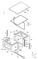
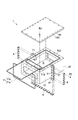
- FIG. 1 is a perspective view showing an overall configuration of a vacuum chamber according to a first embodiment of the present invention. It is a disassembled perspective view of the vacuum chamber of FIG. It is a perspective view explaining the manufacturing method of the vacuum chamber of FIG. It is a disassembled perspective view of the conventional vacuum chamber which concerns on a comparative example. It is a disassembled perspective view of the vacuum chamber by the 2nd Embodiment of this invention. It is a disassembled perspective view of the vacuum chamber by the 3rd Embodiment of this invention. It is a disassembled perspective view of the vacuum chamber by the 4th Embodiment of this invention.
- a chamber according to an embodiment of the present invention includes first and second chamber bodies, first joining means, and a first seal member.
- the first and second chamber bodies are formed in a polyhedral shape each having a first opening end.
- the first joining means forms a first joint by joining the first opening ends of the first and second chamber bodies to each other.
- the first seal member is mounted around the first joint and seals the inside of the first and second chamber bodies.
- first seal member In the chamber configured as described above, after the first and second chamber bodies are joined to each other, a seal member (first seal member) is mounted around the joint (first joint). Therefore, the fine adjustment work of the joining position at the time of joining the chamber main body becomes easy. Furthermore, it is possible to ensure proper sealing performance by improving the mounting workability of the sealing member.
- the chamber is typically a vacuum chamber whose internal pressure is lower than atmospheric pressure, but is not limited thereto, and may be a pressure chamber (positive pressure chamber) whose internal pressure is higher than atmospheric pressure.
- the first and second chamber bodies have a box-like polyhedral shape having a space inside, and the surface on which the first opening end is formed is not particularly limited.
- the first bonding means includes a bonding tool, a bonding material, a bonding jig and the like for bonding the first and second chamber bodies to each other.
- the joint includes a fastener such as a bolt, a screw, or a clamp.
- the bonding material include an adhesive, an adhesive tape, a welding material, a bead formed by welding, and the like.
- the joining jig is typically a temporary fixing positioning jig, but may remain without being removed even after the chamber is assembled. When the first joining means is for temporarily fixing the chamber main body, the joint portion is fixed using various joining tools or joining materials after the sealing member is mounted.
- the first joining portion is formed by joining the open end portions of the chamber bodies to each other.
- a flange portion is formed at the periphery of the open end portion of each chamber body, and the end portions of these flange portions are joined to each other to form the joint portion.
- the joining means for example, a plurality of bolts for fastening both flange portions can be used.
- the seal member may be mounted on the outer peripheral side of the bolt fastening position, or may be mounted on the inner peripheral side of the bolt fastening position. In the former case, a seal portion that maintains airtightness with the chamber body may be formed on the bolt in order to ensure sealing performance at the bolt fastening position.
- the first sealing member is typically composed of an annular sealing member such as an O-ring.
- the cross-sectional shape of the seal member is not particularly limited, and may be circular or polygonal.
- the seal member is mounted so as to elastically adhere to the outer peripheral side of the joint portion, but may be mounted on the inner peripheral side of the joint portion.
- the first joint portion may have a groove for accommodating the first seal member around the first joint portion. Thereby, mounting workability
- the groove may be a groove formed around the first joint by joining the first and second chamber bodies. Thereby, the appropriate sealing performance of a junction part is securable.
- the groove may be separately formed after the chamber body is joined.
- the chamber may further include a fixing member that fixes the first seal member around the first joint.
- a fixing member that fixes the first seal member around the first joint.
- the first and second chamber bodies may each have a second opening end portion that is continuous with the first opening end portion and that is coupled to each other when joined by the first joining means.
- the chamber further includes a chamber plate that covers the second open end portions of the first and second chamber bodies in common.
- the first seal member is mounted between the first seal portion mounted around the first joint portion, the second opening end portions, and the chamber plate. And a second seal portion.
- the first seal portion is mounted around the first joint portion.
- the chamber plate is joined in a state where the second seal portion is mounted along the second opening end.
- the second chamber body may further include a third opening end facing the first opening end and continuing to the second opening end.
- the chamber further includes a third chamber body, second joining means, and a second seal member.
- the third chamber body is formed in a polyhedral shape having a first opening end.
- the second joining unit joins the third opening end portion of the second chamber body and the first opening end portion of the third chamber body to each other, thereby connecting the second joining portion.
- the second seal member is attached around the second joint.
- each chamber main body can be joined in the same procedure as described above by forming the second joint similar to the first joint. is there.
- the second joining means and the second seal member can be configured in the same manner as the first joining means and the first seal member.
- the third chamber main body may further include a second open end that is continuous with the second open end of the second chamber main body when bonded by the second bonding means.
- the chamber plate may be configured to cover the second opening end of each of the first, second, and third chamber bodies in common.
- first seal member and the second seal member can be constituted by a common seal member.
- the common seal member includes a first seal portion attached around the first joint portion, a second seal portion attached around the second joint phrase portion, and the second seal portions. And a third seal portion mounted between the open end portion of the chamber and the chamber plate.
- a chamber according to another embodiment of the present invention includes a plurality of chamber bodies, joining means, and a seal member.
- Each of the plurality of chamber bodies has at least one open end joined to each other.
- the joining means forms a plurality of joints by joining the open end portions of the plurality of chamber bodies to each other.
- the seal member is mounted around each of the plurality of joints and seals the inside of the plurality of chamber bodies.
- the method for manufacturing a chamber includes a step of joining the open end portions of the first chamber body and the second chamber body to each other.
- the seal member is mounted so as to surround a boundary portion of the first and second chamber bodies joined to each other through the opening end portions.
- a seal member is attached so as to surround the boundary between the first and second chamber bodies. Therefore, the fine adjustment work of the joining position at the time of joining the chamber main body is facilitated, and furthermore, the mounting workability of the seal member is improved, so that an appropriate sealability can be secured satisfactorily.
- the method for manufacturing the chamber may further include a step of fixing the seal member to the boundary portion after the seal member is mounted. Thereby, it becomes possible to improve the fixing property of the sealing member with respect to the boundary portion and to ensure a good sealing property.
- the chamber according to the present invention is a vacuum chamber for a vacuum processing apparatus
- a vacuum chamber for a vacuum processing apparatus will be described as an example.
- FIG. 1 is an overall perspective view showing a configuration of a vacuum chamber 1 according to a first embodiment of the present invention.
- FIG. 2 is an exploded perspective view of the vacuum chamber 1.
- FIG. 3 is a perspective view for explaining a manufacturing method of the vacuum chamber 1.
- the vacuum chamber 1 of the present embodiment has a width direction in the X-axis direction, a length direction in the Y-axis direction, and a height direction in the Z-axis direction.
- the vacuum chamber 1 includes a first chamber body 10, a second chamber body 20, a seal member 71, and a chamber plate 50.
- the first chamber main body 10 and the second chamber main body 20 face each other along the length direction, and constitute a main body of the vacuum chamber 1 by being joined to each other.
- Each of the chamber bodies 10 and 20 is made of a metal material such as stainless steel or aluminum alloy, and is formed into a polyhedral shape having space portions S1 and S2 inside through processing steps such as press molding and welding. .
- the chamber bodies 10 and 20 are each formed in a hexahedral shape in which two end portions are open.
- the first and second chamber bodies 10 and 20 have open end portions 11 and 21 (first open end portions) that open in the Y-axis direction, respectively.
- the open end 11 forms one of the four side surfaces of the first chamber body 10.
- the open end 21 forms one of the four side surfaces of the second chamber body 20.
- the first chamber body 10 and the second chamber body 20 are integrated by joining the open end portions 11 and 21 to each other.
- Open end portions 11 and 21 have flange portions 11F and 21F projecting outward, respectively.
- the chamber bodies 10 and 20 are integrated by joining the flange portions 11F and 21F to each other.
- Each flange portion 11F, 21F has a plurality of screw holes h11 and h21, and each screw hole h11 and h21 is formed at a position aligned with each other at the time of joining.
- By screwing the bolt member B1 into the screw holes h11 and h21 both the flange portions 11F and 21F are joined to each other.
- the joint portion J1 (first joint portion) of the first and second chamber bodies 10 and 20 is formed around the open end portions 11 and 21.
- a groove T1 for accommodating the first seal portion 71a of the seal member 71 is formed in the outer peripheral portion of the joint portion J1.
- a notch-shaped groove portion t1 is formed in the outer peripheral edge portion of the joint surface of each flange portion 11F, 21F, and the first and second chamber main bodies 10, 20 are joined, thereby the joint portion J1.
- a groove T1 is formed around the periphery. The groove portion t1 is formed on the outer peripheral side from the formation positions of the screw holes h11 and h21.
- the first and second chamber bodies 10 and 20 have open end portions 12 and 22 (second open end portions) that open in the Z-axis direction, respectively.
- the open end 12 forms the upper surface of the first chamber body 10.
- the open end 22 forms the upper surface of the second chamber body 20.
- the open ends 12 and 22 form one open end that is continuous with each other when the first chamber body 10 and the second chamber body 20 are joined.
- the chamber plate 50 is joined to the chamber bodies 10 and 20 so as to cover the open ends 12 and 22. As a result, a joint J0 is formed between the first and second chamber bodies 10 and 20 and the chamber plate 50.
- a plurality of screw holes h12 and h22 are formed around the open ends 12 and 22, respectively.
- Grooves T12 and T22 for accommodating the second seal portion 71b of the seal member 71 are formed on the inner peripheral sides of the screw holes h12 and h22, respectively.
- the grooves T12 and T22 are continuous with each other when the chamber bodies 10 and 20 are joined to form one annular groove.
- the first chamber body 10 has an opening 19 on the side wall surface facing the opening end 11.
- the second chamber body 20 has an opening 29 on the side wall surface facing the opening end 21.
- These openings 19 and 29 form a passage for transferring a substrate to be processed such as a semiconductor wafer or a glass substrate between the inside and the outside of the vacuum chamber 1.
- a substrate to be processed such as a semiconductor wafer or a glass substrate between the inside and the outside of the vacuum chamber 1.
- One of these openings 19 and 29 may be omitted as necessary. Or when one opening part is not used, you may seal with a cover body.
- the chamber plate 50 has a flat plate shape made of a metal material such as stainless steel or aluminum alloy.
- the chamber plate 50 has a rectangular shape having substantially the same size as the upper surfaces of the chamber bodies 10 and 20 joined to each other.
- a plurality of screw holes h50 that are continuous with the screw holes h12 and h22 of the open ends 12 and 22 are formed at the time of joining to the chamber bodies 10 and 20.
- the seal member 71 is formed of various elastic materials used as a vacuum seal, and includes a first seal portion 71a and a second seal portion 71b.
- the cross-sectional shapes of the first seal portion 71a and the second seal portion 71b are not particularly limited, and may be circular or quadrangular.
- the first seal portion 71a and the second seal portion 71b have an integral structure, but may be formed of separate members.
- the first seal portion 71a is formed in an annular shape in a plane parallel to the XZ plane. After the first and second chamber bodies 10 and 20 are joined, the first seal portion 71a is attached to the groove T1 around the joint portion J1, thereby sealing the joint portion J1.
- the second seal portion 71b is formed in an annular shape in a plane parallel to the XY plane. The second seal portion 71b seals the joint portion J0 by being attached to the grooves T12 and T22 after the first and second chamber bodies 10 and 20 are joined.
- the vacuum chamber 1 of the present embodiment includes a fixing member 6 for fixing the seal member 71 (first seal portion 71a) attached to the joint portion J1 to the joint portion J1.
- the fixing member 6 is attached so as to sandwich the groove T1 formed in the joint portion J1 using the bolt member B3, thereby holding the first seal portion 71a in the groove T1.
- h14 and h24 are screw holes that are screwed into the bolt member B3.
- the fixing member 6 is composed of a plurality of rectangular plate pieces and is arranged at equal intervals along the outer peripheral portion of the joint portion J1. Not only this but the fixing member 6 may be comprised by the elongate board piece corresponding to the length of each edge
- the first chamber body 10 and the second chamber body 20 are joined.
- the first opening end portions 11 and 21 of the chamber bodies 10 and 20 are opposed to each other, and both flange portions 11F and 21F are overlapped.
- both the flange portions 11F and 21F are joined to each other.
- the junction J1 is formed.
- the bolt member B1 is not limited to the configuration in which the bolt member B1 is screwed into the screw holes h11 and h21, and the flange portions 11F and 21F may be sandwiched using a nut member.
- the sliding resistance between the flange portions 11F and 21F is reduced and the joining position is reduced. Can be easily fine-tuned. Thereby, since the assembly of the bolt member B1 becomes easy, workability can be improved.
- the first seal portion 71a of the seal member 71 is elastically deformed and mounted in the groove T1 formed in the outer peripheral portion of the joint portion J1.
- the groove T1 is formed simultaneously with the formation of the joint portion J1. Therefore, the groove T1 is also properly formed by appropriately forming the joint portion J1. Accordingly, it is possible to obtain an appropriate sealing action of the joint portion J1 only by mounting the first seal portion 71a in the groove T1.
- the bolt member B1 since the bolt member B1 is disposed on the inner side of the vacuum chamber 1 with respect to the mounting position of the first seal portion 71a, a predetermined sealing property is provided between the bolt member B1 and the screw holes h11 and h21. It may not be obtained.
- a method such as wrapping a seal tape around the threaded portion of the bolt member B1 or attaching a seal ring to the bolt member B1 (and nut member) can be employed.
- the seal tape and the seal ring constitute a seal portion that maintains airtightness between the bolt member and the chamber body.
- the second seal portion 71b of the seal member 71 is mounted in the grooves T12 and T22 formed in the second open end portions 12 and 22 of the chamber bodies 10 and 20.
- the mounting operation of the second seal portion 71b in the grooves T12 and T22 may be performed before, after, or simultaneously with the mounting operation of the first seal portion 71a with respect to the groove T1 of the joint portion J1.
- the chamber plate 50 is joined to the open ends 12 and 22 of the chamber bodies 10 and 20 by using the bolt member B2. Thereby, the joint portion J0 is formed.
- the second seal portion 71b is sandwiched between the chamber plate 50 and the chamber main bodies 10 and 20, thereby ensuring the sealing performance of the joint portion J0.
- the fixing member 6 is attached around the joint portion J1 using the bolt member B3. Thereby, the position shift of the 1st seal
- the vacuum chamber 1 having the space S therein is manufactured.
- the vacuum chamber 1 is divided into three parts of a first chamber body 10, a second chamber body 20, and a chamber plate 50. For this reason, even if the chamber size is increased, it is possible to avoid an increase in production cost due to an increase in processing equipment, and it is possible to solve a decrease in installation workability and a problem in transportation. Thereby, it is possible to provide a large vacuum chamber that can sufficiently cope with an increase in substrate size.
- FIG. 4 shows a configuration of a conventional vacuum chamber 1000 having a divided structure as a comparative example.
- the vacuum chamber 1000 includes a first chamber body 100, a second chamber body 200, a chamber plate 500, and a seal member 15.
- the first chamber main body 100 and the second chamber main body 200 are divided in the Y-axis direction, and have first opening end portions 111 and 121 that open in the Y-axis direction, respectively.
- the first and second chamber bodies 100 and 200 are joined by making the respective open end portions 111 and 121 face each other and fastening the flange portions 111F and 121F with a plurality of bolt members.
- the seal member 15 has an integral structure of a first seal portion 15a and a second seal portion 15b.
- the first seal portion 15a is mounted between one flange portion 111F and the other flange portion 121F when the first chamber body 100 and the chamber body 200 are joined.
- a groove V1 for accommodating the first seal portion 15a is formed on each joint surface of the flange portions 111F and 121F.
- the chamber plate 500 is joined to the upper surfaces of the chamber main bodies 100 and 200 using a plurality of bolt members so as to cover the second opening end portions 112 and 122 that open in the Z-axis direction.
- the second seal portion 15 b of the seal member 15 is mounted in the grooves V ⁇ b> 21 and V ⁇ b> 22 formed on the joint surfaces of the opening end portions 112 and 122.
- the first seal portion 15a needs to be appropriately positioned between the flange portions 111F and 121F. That is, since the groove V1 for positioning the seal portion 15a is formed on the joint surfaces of the flange portions 111F and 121F, the seal portion 15a is fitted in the groove V1 when the chamber bodies 100 and 200 are assembled. It is necessary to tighten the bolt.
- the seal portion 71a is attached after the formation of the joint portion J1, it is possible to dramatically improve the attachment workability of the seal portion 71a.
- the accuracy of the groove T1 formed on the outer peripheral side of the joint portion J1 is improved by appropriately forming the joint portion J1 as described above. Thereby, the mounting accuracy of the seal portion 71a is improved, and it is possible to ensure an appropriate sealing property of the joint portion J1.
- the joint portion J1 is formed by fastening the flange portions 11F and 21F of the chamber bodies 10 and 20 with the bolt member B1.
- the chamber main bodies 10 and 20 and the chamber plate 50 can be configured to be detachable, and the vacuum chamber 1 can be easily disassembled.
- it is not restricted to this structure For example, you may join both flange parts 11F and 21F by welding. Or you may make it form the junction part J1 by using both flange parts 11F and 21F individually or suitably combining a clamp tool, various adhesive agents, an adhesive tape, etc.
- the open end portions 11 and 21 of the chamber bodies 10 and 20 may be directly joined without forming the flange portions 11F and 21F.
- the joint forming the joint J1 is not limited to the example that remains as the final product.
- an appropriate joining jig is used for joining the flange portions 11F and 21F, and after the seal portion 71a is mounted, the joining jig is removed and both flanges are joined by another joining means (joining tool such as a bolt or joining material). It is also possible to join the parts.
- the seal portion mounting groove T1 formed on the outer peripheral surface of the joint portion J1 is not limited to the example formed simultaneously with the formation of the joint portion J1 as described above.
- a mounting groove for the seal portion 71a may be formed on the outer peripheral portion thereof, or a sheet surface on which the seal portion 71a is mounted may be separately provided.
- FIG. 5 is an exploded perspective view showing the configuration of the vacuum chamber 2 according to the second embodiment of the present invention.
- portions corresponding to those of the first embodiment described above are denoted by the same reference numerals, and detailed description thereof is omitted.
- the vacuum chamber 2 of the present embodiment includes a first chamber body 10, a second chamber body 20, a seal member 72, a first chamber plate 51, and a second chamber plate 52.
- the first chamber body 10 has an opening end 11 (first opening end) that opens in the Y-axis direction, and two opening ends 12 and 13 (second opening end) that open in the Z-axis direction. And have.
- the second chamber body 20 includes an opening end 21 (first opening end) that opens in the Y-axis direction and two opening ends 22 and 23 (second opening) that open in the Z-axis direction. End).
- the first chamber body 10 and the second chamber body 20 are joined to each other via the first seal portion 72 a of the seal member 72.
- the first and second chamber bodies 10 and 20 and the first chamber plate 51 are joined to each other via the second seal portion 72 b of the seal member 72.
- the first and second chamber bodies 10 and 20 and the second chamber plate 52 are joined to each other via the third seal portion 72 c of the seal member 72.
- Each of the opening end portions 11 and 21 of the first and second chamber bodies 10 and 20 has flange portions 11F and 21F protruding in the X-axis direction, and the flange portions 11F and 21F are made of a plurality of bolt members.
- the first and second chamber main bodies 10 and 20 are joined by fastening through the two.
- the flange portions 11F and 21F form a joint portion J1 (first joint portion) of the chamber bodies 10 and 20.
- Groove portions t1 for forming a groove for accommodating the seal portion 72a when the joint portion J1 is formed are formed on the peripheral portions of the joint surfaces of the flange portions 11F and 21F, respectively.
- Grooves T12 and T22 for accommodating the second seal portion 72b are formed in the open end portions 12 and 22 of the first and second chamber bodies 10 and 20, respectively. These grooves T12 and T22 are combined when the chamber bodies 10 and 20 are joined to form one annular groove. Similarly, grooves for accommodating the third seal portion 72c are respectively formed in the opening end portions 13 and 23 of the first and second chamber bodies 10 and 20, respectively. When the chamber bodies 10 and 20 are joined, they are combined to form one annular groove.
- the seal member 72 has a first seal portion 72a, a second seal portion 72b, and a third seal portion 72c, which are integrally formed.
- the first seal portion 72a is formed so as to connect the annular second and third seal portions 72b and 72c to each other.
- the first chamber plate 51 is joined to the upper surfaces of the chamber bodies 10 and 20 using a plurality of bolt members via the second seal portion 72b so as to cover the open end portions 12 and 22.
- the second chamber plate 52 is joined to the lower surfaces of the chamber bodies 10 and 20 using a plurality of bolt members through the third seal portion 72c so as to cover the open end portions 13 and 23.
- the first and second chamber bodies 10 and 20 are joined to each other, and then a seal portion 72a is mounted around the joined portion J1, as in the first embodiment. Is done.
- the seal portion 72a is attached, the second seal portion 72b is attached to the grooves T12 and T22 of the open end portions 12 and 22, and the third seal portion 72c is attached to the groove of the open end portions 13 and 23. Is done.
- the first and second chamber plates 51 and 52 are joined to the chamber bodies 10 and 20, respectively.
- sticker part 72a is hold
- the vacuum chamber 2 of the present embodiment is manufactured. Also according to the present embodiment, the same operational effects as those of the first embodiment described above can be obtained.
- FIG. 6 is an exploded perspective view showing the configuration of the vacuum chamber 3 according to the third embodiment of the present invention.
- portions corresponding to those of the first embodiment described above are denoted by the same reference numerals, and detailed description thereof is omitted.
- the vacuum chamber 3 of the present embodiment includes a first chamber body 10, a second chamber body 20, a third chamber body 30, a fourth chamber body 40, a seal member 73, a chamber plate 50, Is provided.
- the first and fourth chamber bodies 10 and 40 have opening end portions 11 and 41 (first opening end portion) that open in the Y-axis direction and opening end portions 12 and 42 (second opening) that open in the Z-axis direction. Open end).
- the second and third chamber bodies 20 and 30 have opening end portions 21 and 31 (first opening end portion) that open in the Y-axis direction and opening end portions 22 and 32 (second opening) that open in the Z-axis direction. Open end portions) and open end portions 24 and 34 (third open end portions) facing the open end portions 21 and 31.
- the first chamber body 10 and the second chamber body 20 are joined to each other via the first seal portion 73a of the seal member 73.
- the second chamber body 20 and the third chamber body 30 are joined to each other via the second seal portion 73 b of the seal member 73.
- the third chamber body 30 and the fourth chamber body 40 are joined to each other via the third seal portion 73 c of the seal member 73.
- the first to fourth chamber bodies 10 to 40 and the chamber plate 51 are joined to each other via the fourth seal portion 73 d of the seal member 73.
- the open end portions 11 and 21 of the first and second chamber bodies 10 and 20 have flange portions 11F and 21F, respectively, and these flange portions 11F and 21F are fastened through a plurality of bolt members.
- the first and second chamber bodies 10 and 20 are joined.
- the flange portions 11F and 21F form a joint portion J1 (first joint portion) of the chamber bodies 10 and 20.
- Groove portions t1 for forming a groove for accommodating the first seal portion 73a when the joint portion J1 is formed are formed on the peripheral edge portions of the joint surfaces of the flange portions 11F and 21F, respectively.
- the open end portions 24 and 31 of the second and third chamber bodies 20 and 30 have flange portions 24F and 31F, respectively, and these flange portions 24F and 31F are fastened via a plurality of bolt members.
- the second and third chamber bodies 20, 30 are joined.
- the flange portions 24F and 31F form a joint portion J2 (second joint portion) of the chamber bodies 20 and 30.
- Groove portions t2 for forming a groove for accommodating the second seal portion 73b when the joint portion J2 is formed are formed on the peripheral edge portions of the joint surfaces of the flange portions 24F and 31F, respectively.
- the open end portions 34 and 41 of the third and fourth chamber bodies 30 and 40 have flange portions 34F and 41F, respectively, and these flange portions 34F and 41F are fastened through a plurality of bolt members.
- the third and fourth chamber bodies 30, 40 are joined.
- the flange portions 34F and 41F form a joint portion J3 (third joint portion) of the chamber bodies 30 and 40.
- Groove portions t3 for forming a groove for accommodating the third seal portion 73c when the joint portion J3 is formed are formed on the peripheral portions of the joint surfaces of the flange portions 34F and 41F, respectively.
- Grooves T12, T22, T32, and T42 for accommodating the fourth seal portion 73d are formed in the open end portions 12, 22, 32, and 42 of the first to fourth chamber bodies 10 to 40, respectively. ing. These grooves T12, T22, T32 and T42 are combined when the chamber bodies 10 to 40 are joined to form one annular groove.
- the seal member 73 includes a first seal portion 73a, a second seal portion 73b, a third seal portion 73c, and a fourth seal portion 73d, which are integrally formed.
- the first to third seal portions 73a to 73c are formed so as to be connected to the annular fourth seal portion 73d.
- the chamber plate 50 is joined to the upper surfaces of the chamber bodies 10 to 40 using a plurality of bolt members via the fourth seal portion 73d so as to cover the open end portions 12, 22, 32, and 42.
- seal portions 73a to 73c are mounted around the joints J1 to J3.
- the fourth seal portion 73d is attached to the grooves T12, T22, T32, T42 of the open end portions 12, 22, 32, 42.
- the chamber plate 50 is joined to the chamber bodies 10 to 40, respectively.
- the fixing member 6 is joined to the joint portions J1 to J4, respectively, whereby the first seal portion 73a is held by the joint portions J1 to J4.
- the vacuum chamber 3 of the present embodiment is manufactured. Even in the case where the chamber main body is divided into a plurality of three or more as in the present embodiment, the same operational effects as those of the first embodiment described above can be obtained.
- FIG. 7 is an exploded perspective view showing the configuration of the vacuum chamber 4 according to the fourth embodiment of the present invention.
- portions corresponding to those of the above-described second embodiment are denoted by the same reference numerals, and detailed description thereof is omitted.
- the vacuum chambers 1 to 3 of the above embodiments are divided in the X-axis direction, whereas the vacuum chamber 4 of the present embodiment has the chamber bodies in the X-axis direction and the Y-axis direction. It is divided into That is, the vacuum chamber 4 of the present embodiment includes a first chamber body 10A, a second chamber body 10B, a third chamber body 20A, a fourth chamber body 20B, a seal member 74, and a first member.
- the chamber plate 51 and the second chamber plate 52 are provided.
- the first and second chamber bodies 10A and 20A have flange portions 19AF and 19BF joined in the X-axis direction, respectively.
- the flange portions 19AF and 19BF are joined to each other by a plurality of bolt members, whereby the first chamber body unit 110 having the joint portion J4 is configured.
- Groove portions t4 for accommodating the seal portions d1 and d2 of the seal member 74 are formed in the peripheral portions of the joint surfaces of the flange portions 19AF and 19BF, respectively.
- the first chamber body 10A and the second chamber body 10B are joined to each other, whereby an opening 19 is formed on one side surface of the first chamber body unit 110.
- the first and second chamber bodies 10 ⁇ / b> A and 10 ⁇ / b> B have grooves T ⁇ b> 19 ⁇ / b> A and T ⁇ b> 19 ⁇ / b> B that accommodate the seal portion 74 d of the seal member 74 along the periphery of the opening portion 19.
- the third and fourth chamber bodies 20A and 20B have flange portions 29AF and 29BF joined in the X-axis direction, respectively.
- the flange portions 29AF and 29BF are joined to each other by a plurality of bolt members, whereby the second chamber body unit 120 having the joint portion J5 is configured.
- Groove portions t5 for receiving the seal portions e1 and e2 of the seal member 74 are formed in the peripheral portions of the joint surfaces of the flange portions 29AF and 29BF, respectively.
- the third chamber body 20A and the fourth chamber body 20B are joined to each other, whereby an opening 29 is formed on one side surface of the second chamber body unit 120.
- the third and fourth chamber bodies 20 ⁇ / b> A and 20 ⁇ / b> B have grooves (not shown) in which the seal portion 74 e of the seal member 74 is accommodated along the periphery of the opening 29.
- the first chamber body unit 110 includes an opening end portion 11 (first opening end portion) that opens in the Y-axis direction, and two opening end portions 12 and 13 (second opening end portions) that open in the Z-axis direction. ).
- the second chamber body unit 120 includes an opening end 21 (first opening end) that opens in the Y-axis direction, and two opening ends 22 and 23 (second opening) that open in the Z-axis direction. Open end).
- the first chamber body unit 110 and the second chamber body unit 120 are joined to each other via the seal portion 74 a of the seal member 74.
- the first and second chamber body units 110 and 120 and the first chamber plate 51 are joined to each other via the seal portion 74 b of the seal member 74.
- the first and second chamber body units 110 and 120 and the second chamber plate 52 are joined to each other via the seal portion 74 c of the seal member 74.
- the open end portions 11 and 21 of the first and second chamber body units 110 and 120 have flange portions 11AF, 11BF, 21AF, and 21BF, respectively, that protrude in the X-axis direction.
- the flange portions 11AF, 11BF, 21AF, and 21BF form a joint portion J1 (first joint portion) of the chamber body units 110 and 120.
- Groove portions t1 for forming a groove that accommodates the seal portion 74a when the joint portion J1 is formed are respectively formed on the peripheral portions of the joint surfaces of the flange portions.
- Grooves T12A, T12B, T22A, T22B for accommodating the seal portion 74b are formed in the open end portions 12, 22 of the first and second chamber body units 110, 120, respectively. These grooves are united when the chamber body units 110 and 120 are joined to form one annular groove. Similarly, the opening end portions 13 and 23 of the first and second chamber body units 110 and 120 are respectively formed with grooves for accommodating the seal portion 74c, and these grooves are formed in the chamber body. When the units 110 and 120 are joined, they are combined to form one annular groove.
- the seal member 74 includes a first seal portion 74a, a second seal portion 74b, a third seal portion 74c, fourth seal portions d1, d2, fifth seal portions e1, e2, 6 seal portions 74d and a seventh seal portion 74e, which are integrally formed.
- the first seal portion 74a is formed to connect the annular second and third seal portions 74b and 74c to each other.
- the fourth seal portions d1 and d2 are formed so as to connect the annular sixth seal portion 74d to the second and third seal portions 74b and 74c.
- the fifth seal portions 74e1 and 74e2 are formed so as to connect the annular seventh seal portion 74e to the second and third seal portions 74b and 74c.
- the first chamber plate 51 is joined to the upper surfaces of the chamber body units 110 and 120 using a plurality of bolt members via the seal portion 74b so as to cover the open end portions 12 and 22.
- the second chamber plate 52 is joined to the lower surfaces of the chamber main body units 110 and 120 using a plurality of bolt members via the seal portion 74 c so as to cover the open end portions 13 and 23.
- first and second chamber body units 110 and 120 are assembled, the first and second chamber body units 110 and 120 are joined to each other.
- a seal portion 74a is mounted around the joint portion J1.
- the seal portions d1 and d2 are attached to the groove portion t4 around the joint portion J4, and the seal portions e1 and e2 are attached to the groove portion t5 around the joint portion J5.
- the seal portion 74b is attached to the grooves T12A, T12B, T22A, T22B of the open end portions 12 and 22, and the seal portion 74c is attached to the groove of the open end portions 13 and 23.
- the first and second chamber plates 51 and 52 are joined to the chamber body units 110 and 120, respectively.
- the seal portion 74d is attached to the grooves T19A and T19B around the opening portion 19, and the seal portion 74e is attached to the groove around the opening portion 29.
- the sealing member 74a is hold
- the vacuum chamber 4 of the present embodiment is manufactured. Even in the case where the chamber main body is divided into a plurality of four or more as in the present embodiment, the same effects as those of the first embodiment described above can be obtained.
- the present invention is not limited to this, and the present invention is also applied to a pressure chamber (positive pressure chamber) in which the internal pressure is maintained higher than the external pressure.
- the invention is applicable.
- the chamber main body is formed in a substantially hexahedral shape, but may be formed in another polyhedral shape such as an octahedral shape instead.
- the present invention is not limited to an example in which two chamber main bodies are bonded to one bonding section, and one bonding section may be formed at the open ends of three or more chamber main bodies.
- the seal member is attached to the outer peripheral portion of the joint portion of the chamber body, but the seal member may be attached to the inner peripheral portion of the joint portion. This configuration is advantageous when the present invention is applied to a positive pressure chamber.
Landscapes
- Chemical & Material Sciences (AREA)
- Chemical Kinetics & Catalysis (AREA)
- Engineering & Computer Science (AREA)
- Materials Engineering (AREA)
- Mechanical Engineering (AREA)
- Metallurgy (AREA)
- Organic Chemistry (AREA)
- General Chemical & Material Sciences (AREA)
- Pressure Vessels And Lids Thereof (AREA)
- Physical Vapour Deposition (AREA)
- Drying Of Semiconductors (AREA)
Abstract
Description
上記第1及び第2のチャンバ本体は、第1の開口端部をそれぞれ有する多面体形状で形成されている。上記第1の接合手段は、上記第1及び第2のチャンバ本体の各々の上記第1の開口端部を相互に接合することで第1の接合部を形成する。上記第1のシール部材は、上記第1の接合部の周囲に装着され、上記第1及び第2のチャンバ本体の内部を密封する。
上記複数のチャンバ本体は、相互に接合される少なくとも1つの開口端部をそれぞれ有する。上記接合手段は、上記複数のチャンバ本体の各々の上記開口端部を相互に接合することで複数の接合部を形成する。上記シール部材は、上記複数の接合部のそれぞれの周囲に装着され上記複数のチャンバ本体の内部を密封する。
上記第1及び第2のチャンバ本体は、第1の開口端部をそれぞれ有する多面体形状で形成されている。上記第1の接合手段は、上記第1及び第2のチャンバ本体の各々の上記第1の開口端部を相互に接合することで第1の接合部を形成する。上記第1のシール部材は、上記第1の接合部の周囲に装着され、上記第1及び第2のチャンバ本体の内部を密封する。
このような構成とすることにより、上記チャンバを構成するチャンバ本体の設計自由度が高められ、仕様や取り扱い性、加工性などに応じてチャンバ本体を構成することができる。上記第2の開口端部は、上記第1の接合手段による接合時、上記第1の開口端部と同一平面上に位置してもよいし、そうでなくてもよい。
この場合、各チャンバ本体を接合した後、第1の接合部の周囲に第1のシール部が装着される。そして、第2のシール部が第2の開口端部に沿って装着された状態で、チャンバプレートが接合される。
上記第3のチャンバ本体は、第1の開口端部を有する多面体形状に形成される。上記第2の接合手段は、上記第2のチャンバ本体の第3の開口端部と、上記第3のチャンバ本体の第1の開口端部とを相互に接合することで第2の接合部を形成する。上記第2のシール部材は、上記第2の接合部の周囲に装着される。
上記複数のチャンバ本体は、相互に接合される少なくとも1つの開口端部をそれぞれ有する。上記接合手段は、上記複数のチャンバ本体の各々の上記開口端部を相互に接合することで複数の接合部を形成する。上記シール部材は、上記複数の接合部のそれぞれの周囲に装着され上記複数のチャンバ本体の内部を密封する。
図1は本発明の第1の実施形態による真空チャンバ1の構成を示す全体斜視図である。図2は真空チャンバ1の分解斜視図である。図3は、真空チャンバ1の製造方法を説明する斜視図である。
図5は本発明の第2の実施形態による真空チャンバ2の構成を示す分解斜視図である。なお、図において上述の第1の実施形態と対応する部分については同一の符号を付し、その詳細な説明は省略する。
図6は本発明の第3の実施形態による真空チャンバ3の構成を示す分解斜視図である。なお、図において上述の第1の実施形態と対応する部分については同一の符号を付し、その詳細な説明は省略する。
図7は本発明の第4の実施形態による真空チャンバ4の構成を示す分解斜視図である。なお、図において上述の第2の実施形態と対応する部分については同一の符号を付し、その詳細な説明は省略する。
6…固定部材
10、10A、10B、20、20A、20B、30、40…チャンバ本体
11、21、31、41…開口端部(第1の開口端部)
12、13、22、23、32、42…開口端部(第2の開口端部)
24、34…開口端部(第3の開口端部)
50、51、52…チャンバプレート
110、120…チャンバ本体ユニット
71、72、73、74…シール部材
J1、J2、J3、J4、J5…接合部
T1、T21、T22、T32、T42…溝
Claims (15)
- 第1の開口端部をそれぞれ有する多面体形状の第1及び第2のチャンバ本体と、
前記第1及び第2のチャンバ本体の各々の前記第1の開口端部を相互に接合することで第1の接合部を形成する第1の接合手段と、
前記第1の接合部の周囲に装着され前記第1及び第2のチャンバ本体の内部を密封する第1のシール部材と
を具備するチャンバ。 - 請求項1に記載のチャンバであって、
前記第1の接合部は、
前記第1の開口端部に形成された第1の接合面と、
前記第2の開口端部に形成され前記第1の接合面と対向する第2の接合面とを有し、
前記第1の接合手段は、前記第1の接合面及び前記第2の接合面を貫通し、前記第1の接合面及び第2の接合面を相互に接合させる複数の締結具である
チャンバ。 - 請求項2に記載のチャンバであって、
前記第1のシール部材は、前記締結具の貫通位置よりも外周側の、前記第1の接合部の周囲に装着される
チャンバ。 - 請求項3に記載のチャンバであって、
前記締結具は、前記第1のチャンバ本体及び前記第2のチャンバ本体に対する気密性を保持するシール部を有する
チャンバ。 - 請求項1に記載のチャンバであって、
前記第1の接合部は、その周囲に、前記第1のシール部材を収容するための溝を有する
チャンバ。 - 請求項5に記載のチャンバであって、
前記溝は、前記第1及び第2のチャンバ本体を接合することで前記第1の接合部の周囲に形成される溝部である
チャンバ。 - 請求項1に記載のチャンバであって、
前記第1のシール部材を前記第1の接合部の周囲に固定する固定部材をさらに具備する
チャンバ。 - 請求項1に記載のチャンバであって、
前記第1及び第2のチャンバ本体は、前記第1の開口端部と連続し、前記第1の接合手段による接合時に互いに結合する第2の開口端部をそれぞれ有し、
前記チャンバは、前記第1及び第2のチャンバ本体の前記第2の開口端部を共通に被覆するチャンバプレートをさらに具備する
チャンバ。 - 請求項8に記載のチャンバであって、
前記第1のシール部材は、
前記第1の接合部の周囲に装着される第1のシール部と、
前記各第2の開口端部と前記チャンバプレートとの間に装着される第2のシール部とを有する
チャンバ。 - 請求項8に記載のチャンバであって、
前記第2のチャンバ本体は、前記第1の開口端部と対向し、かつ、前記第2の開口端部と連続する第3の開口端部をさらに有し、
前記チャンバは、
第1の開口端部とを有する多面体形状の第3のチャンバ本体と、
前記第2のチャンバ本体の前記第3の開口端部と、前記第3のチャンバ本体の前記第1の開口端部とを相互に接合することで第2の接合部を形成する第2の接合手段と、
前記第2の接合部の周囲に装着される第2のシール部材とをさらに具備する
チャンバ。 - 請求項10に記載のチャンバであって、
前記第3のチャンバ本体は、前記第2の接合手段による接合時に前記第2のチャンバ本体の前記第2の開口端部と連続する第2の開口端部をさらに有し、
前記チャンバプレートは、前記第1、第2及び第3のチャンバ本体の各々の前記第2の開口端部を共通に被覆する
チャンバ。 - 請求項11に記載のチャンバであって、
前記第1のシール部材と前記第2のシール部材とは共通のシール部材からなり、
前記共通のシール部材は、
前記第1の接合部の周囲に装着される第1のシール部と、
前記第2の接合部の周囲に装着される第2のシール部と、
前記各第2の開口端部と前記チャンバプレートとの間に装着される第3のシール部とを有する
チャンバ。 - 相互に接合される少なくとも1つの開口端部をそれぞれ有する複数のチャンバ本体と、
前記複数のチャンバ本体の各々の前記開口端部を相互に接合することで複数の接合部を形成する接合手段と、
前記複数の接合部のそれぞれの周囲に装着され前記複数のチャンバ本体の内部を密封するシール部材と
を具備するチャンバ。 - 第1のチャンバ本体と第2のチャンバ本体の各々の開口端部を相互に接合し、
前記各開口端部を介して相互に接合された前記第1及び第2のチャンバ本体の境界部を囲むようにシール部材を装着する
チャンバの製造方法。 - 請求項14に記載のチャンバの製造方法であって、
前記シール部材の装着後、前記シール部材を前記境界部に固定する工程をさらに有する
チャンバの製造方法。
Priority Applications (2)
| Application Number | Priority Date | Filing Date | Title |
|---|---|---|---|
| CN2010800013711A CN102007575A (zh) | 2009-02-06 | 2010-02-01 | 工作腔及其制作方法 |
| JP2010534296A JP5158994B2 (ja) | 2009-02-06 | 2010-02-01 | チャンバ |
Applications Claiming Priority (2)
| Application Number | Priority Date | Filing Date | Title |
|---|---|---|---|
| JP2009025985 | 2009-02-06 | ||
| JP2009-025985 | 2009-02-06 |
Publications (1)
| Publication Number | Publication Date |
|---|---|
| WO2010089986A1 true WO2010089986A1 (ja) | 2010-08-12 |
Family
ID=42541897
Family Applications (1)
| Application Number | Title | Priority Date | Filing Date |
|---|---|---|---|
| PCT/JP2010/000588 Ceased WO2010089986A1 (ja) | 2009-02-06 | 2010-02-01 | チャンバ及びその製造方法 |
Country Status (5)
| Country | Link |
|---|---|
| JP (1) | JP5158994B2 (ja) |
| KR (1) | KR20100123885A (ja) |
| CN (1) | CN102007575A (ja) |
| TW (1) | TW201036093A (ja) |
| WO (1) | WO2010089986A1 (ja) |
Families Citing this family (3)
| Publication number | Priority date | Publication date | Assignee | Title |
|---|---|---|---|---|
| KR20120062574A (ko) | 2010-12-06 | 2012-06-14 | 현대자동차주식회사 | 에어클리너 필터 점검주기 인지시스템 |
| KR102077271B1 (ko) * | 2017-11-24 | 2020-04-07 | 코스텍시스템(주) | 게이트 밸브 하우징 및 이의 제조방법 |
| KR102293803B1 (ko) * | 2021-03-22 | 2021-08-24 | 최창두 | 반도체 챔버 제조 방법 |
Citations (5)
| Publication number | Priority date | Publication date | Assignee | Title |
|---|---|---|---|---|
| JPH01312271A (ja) * | 1988-06-13 | 1989-12-18 | Hitachi Ltd | 大型真空容器の真空シール構造 |
| JP2003117655A (ja) * | 2001-10-12 | 2003-04-23 | Toyo Jigu:Kk | 真空容器 |
| JP2006137995A (ja) * | 2004-11-12 | 2006-06-01 | Ulvac Japan Ltd | 真空チャンバ |
| JP2007299785A (ja) * | 2006-04-27 | 2007-11-15 | Tokyo Electron Ltd | シール部材、減圧容器、減圧処理装置、減圧容器のシール機構、および減圧容器の製造方法 |
| JP2009302106A (ja) * | 2008-06-10 | 2009-12-24 | Tokyo Electron Ltd | チャンバ及び処理装置 |
-
2010
- 2010-02-01 JP JP2010534296A patent/JP5158994B2/ja active Active
- 2010-02-01 KR KR1020107021587A patent/KR20100123885A/ko not_active Ceased
- 2010-02-01 CN CN2010800013711A patent/CN102007575A/zh active Pending
- 2010-02-01 WO PCT/JP2010/000588 patent/WO2010089986A1/ja not_active Ceased
- 2010-02-05 TW TW099103475A patent/TW201036093A/zh unknown
Patent Citations (5)
| Publication number | Priority date | Publication date | Assignee | Title |
|---|---|---|---|---|
| JPH01312271A (ja) * | 1988-06-13 | 1989-12-18 | Hitachi Ltd | 大型真空容器の真空シール構造 |
| JP2003117655A (ja) * | 2001-10-12 | 2003-04-23 | Toyo Jigu:Kk | 真空容器 |
| JP2006137995A (ja) * | 2004-11-12 | 2006-06-01 | Ulvac Japan Ltd | 真空チャンバ |
| JP2007299785A (ja) * | 2006-04-27 | 2007-11-15 | Tokyo Electron Ltd | シール部材、減圧容器、減圧処理装置、減圧容器のシール機構、および減圧容器の製造方法 |
| JP2009302106A (ja) * | 2008-06-10 | 2009-12-24 | Tokyo Electron Ltd | チャンバ及び処理装置 |
Also Published As
| Publication number | Publication date |
|---|---|
| TW201036093A (en) | 2010-10-01 |
| CN102007575A (zh) | 2011-04-06 |
| JP5158994B2 (ja) | 2013-03-06 |
| JPWO2010089986A1 (ja) | 2012-08-09 |
| KR20100123885A (ko) | 2010-11-25 |
Similar Documents
| Publication | Publication Date | Title |
|---|---|---|
| JPH09209150A (ja) | 真空チャンバ及びその製造方法 | |
| TWI493640B (zh) | Workpiece Adhesive Chuck Device and Workpiece Clamping Machine | |
| JP5158994B2 (ja) | チャンバ | |
| KR102532102B1 (ko) | 개스킷 및 그 제조방법 | |
| JP2000514601A (ja) | チャンバ連結o―リングおよびその構成方法 | |
| TWI763886B (zh) | 閘閥的安裝構造 | |
| KR101802286B1 (ko) | 반도체 및 디스플레이 제조 설비용 진공배관 지지장치 | |
| JP2020504269A (ja) | フランジ継手の平型ガスケット用の取付装置 | |
| KR101195125B1 (ko) | 조립형 진공챔버 | |
| WO2005035186A1 (ja) | 位置決め装置及びそれを備えるクランピングシステム | |
| KR20040084863A (ko) | 진공 챔버 조립체 | |
| JP6221677B2 (ja) | 配管接続方法及び配管接続継手 | |
| KR20070082055A (ko) | 기판 진공처리용 로드락 챔버 | |
| US9847241B2 (en) | Transport module for a semiconductor fabrication device or coupling device | |
| JP5580004B2 (ja) | 真空容器、および真空処理装置 | |
| JP2006137995A (ja) | 真空チャンバ | |
| JP5403716B2 (ja) | 組立て式密閉チャンバ | |
| JP5427317B2 (ja) | 密閉チャンバ | |
| JP5225236B2 (ja) | ウェーハ用ホルダ | |
| JP2009144773A (ja) | 金属積層形ガスケット構造 | |
| KR100743012B1 (ko) | 강성보강구조를 갖는 홀더 구조체 | |
| JP4117928B2 (ja) | 真空容器 | |
| JP2006153624A (ja) | 漏洩試験用プラグ | |
| JPH09159492A (ja) | 計器類の読取り用覗き窓枠 | |
| JP5225228B2 (ja) | ウェーハ用ホルダ |
Legal Events
| Date | Code | Title | Description |
|---|---|---|---|
| WWE | Wipo information: entry into national phase |
Ref document number: 201080001371.1 Country of ref document: CN |
|
| WWE | Wipo information: entry into national phase |
Ref document number: 2010534296 Country of ref document: JP |
|
| ENP | Entry into the national phase |
Ref document number: 20107021587 Country of ref document: KR Kind code of ref document: A |
|
| 121 | Ep: the epo has been informed by wipo that ep was designated in this application |
Ref document number: 10738329 Country of ref document: EP Kind code of ref document: A1 |
|
| NENP | Non-entry into the national phase |
Ref country code: DE |
|
| 122 | Ep: pct application non-entry in european phase |
Ref document number: 10738329 Country of ref document: EP Kind code of ref document: A1 |