WO2010089979A1 - 磁性素子 - Google Patents
磁性素子 Download PDFInfo
- Publication number
- WO2010089979A1 WO2010089979A1 PCT/JP2010/000492 JP2010000492W WO2010089979A1 WO 2010089979 A1 WO2010089979 A1 WO 2010089979A1 JP 2010000492 W JP2010000492 W JP 2010000492W WO 2010089979 A1 WO2010089979 A1 WO 2010089979A1
- Authority
- WO
- WIPO (PCT)
- Prior art keywords
- core member
- core
- magnetic element
- terminal
- base
- Prior art date
- Legal status (The legal status is an assumption and is not a legal conclusion. Google has not performed a legal analysis and makes no representation as to the accuracy of the status listed.)
- Ceased
Links
Images



Classifications
-
- H—ELECTRICITY
- H01—ELECTRIC ELEMENTS
- H01F—MAGNETS; INDUCTANCES; TRANSFORMERS; SELECTION OF MATERIALS FOR THEIR MAGNETIC PROPERTIES
- H01F17/00—Fixed inductances of the signal type
- H01F17/04—Fixed inductances of the signal type with magnetic core
- H01F17/045—Fixed inductances of the signal type with magnetic core with core of cylindric geometry and coil wound along its longitudinal axis, i.e. rod or drum core
-
- H—ELECTRICITY
- H01—ELECTRIC ELEMENTS
- H01F—MAGNETS; INDUCTANCES; TRANSFORMERS; SELECTION OF MATERIALS FOR THEIR MAGNETIC PROPERTIES
- H01F27/00—Details of transformers or inductances, in general
- H01F27/28—Coils; Windings; Conductive connections
- H01F27/29—Terminals; Tapping arrangements for signal inductances
- H01F27/292—Surface mounted devices
-
- H—ELECTRICITY
- H01—ELECTRIC ELEMENTS
- H01F—MAGNETS; INDUCTANCES; TRANSFORMERS; SELECTION OF MATERIALS FOR THEIR MAGNETIC PROPERTIES
- H01F5/00—Coils
- H01F5/04—Arrangements of electric connections to coils, e.g. leads
- H01F2005/043—Arrangements of electric connections to coils, e.g. leads having multiple pin terminals, e.g. arranged in two parallel lines at both sides of the coil
-
- H—ELECTRICITY
- H01—ELECTRIC ELEMENTS
- H01F—MAGNETS; INDUCTANCES; TRANSFORMERS; SELECTION OF MATERIALS FOR THEIR MAGNETIC PROPERTIES
- H01F27/00—Details of transformers or inductances, in general
- H01F27/06—Mounting, supporting or suspending transformers, reactors or choke coils not being of the signal type
- H01F2027/065—Mounting on printed circuit boards
-
- H—ELECTRICITY
- H01—ELECTRIC ELEMENTS
- H01F—MAGNETS; INDUCTANCES; TRANSFORMERS; SELECTION OF MATERIALS FOR THEIR MAGNETIC PROPERTIES
- H01F3/00—Cores, Yokes, or armatures
- H01F3/10—Composite arrangements of magnetic circuits
-
- H—ELECTRICITY
- H01—ELECTRIC ELEMENTS
- H01F—MAGNETS; INDUCTANCES; TRANSFORMERS; SELECTION OF MATERIALS FOR THEIR MAGNETIC PROPERTIES
- H01F41/00—Apparatus or processes specially adapted for manufacturing or assembling magnets, inductances or transformers; Apparatus or processes specially adapted for manufacturing materials characterised by their magnetic properties
- H01F41/02—Apparatus or processes specially adapted for manufacturing or assembling magnets, inductances or transformers; Apparatus or processes specially adapted for manufacturing materials characterised by their magnetic properties for manufacturing cores, coils, or magnets
- H01F41/04—Apparatus or processes specially adapted for manufacturing or assembling magnets, inductances or transformers; Apparatus or processes specially adapted for manufacturing materials characterised by their magnetic properties for manufacturing cores, coils, or magnets for manufacturing coils
- H01F41/10—Connecting leads to windings
Definitions
- the present invention relates to a magnetic element used in various electronic devices.
- FIG. 8 is a perspective view of the magnetic element 100 of this type (with the ring core removed).
- the magnetic element 100 shown in this figure is a transformer, and a terminal 121 of the coil 120 is connected to two of the plurality of terminals 111 arranged on the front side and two of the plurality of terminals 111 arranged on the back side. I'm bald.
- a portion of the drum core 130 where the coil 120 is disposed (hereinafter, this portion is referred to as a reel portion 131).
- a terminal 121 (conductive wire) of the coil 120 extends toward a portion on which the ring core is placed (hereinafter, this portion is referred to as a ring placement portion 112).
- the terminal 121 is positioned on the ring placement unit 112, or the terminal 121 interferes with the ring core.
- the terminal 121 When the terminal 121 is positioned on the ring mounting unit 112, the terminal 121 is sandwiched between the ring core and the ring mounting unit 112. In addition, when the ring core and the terminal 121 interfere with each other, it is difficult to appropriately place the ring core on the ring placement unit 112. In any case, since the ring core is inclined or the ring core is wobbled, the ring core is not positioned at an accurate position. In other words, in the configuration shown in FIG. 8, it is necessary to place the ring core on the ring mounting unit 112 while preventing the terminal 121 from being positioned on the ring mounting unit 112, which increases the man-hours. The terminal 121 is obstructive when the ring core is attached.
- the present invention has been made on the basis of the above circumstances, and an object of the present invention is to provide a magnetic element capable of preventing the end of the coil from being positioned on the ring mounting portion.
- a first side surface of a magnetic element includes a first core member having a winding frame portion and a first core member disposed opposite to the entire circumference of the outer periphery of the first core member. 2 core member, a coil disposed on the winding frame portion by winding of the conductive wire, and a first placement portion on which the first core member is placed, and is raised from the first placement portion.
- a second mounting portion that is provided between both ends and on which the second core member is mounted, and a base on which a plurality of terminals protrude from the side are provided.
- the end portion of the two mounting portions is provided with a protruding portion extending in a direction away from the second mounting portion, the protruding portion is provided smaller than the thickness of the base, and the end of the coil is the protruding portion.
- the second core member is entangled with the terminal after being positioned on the back surface opposite to the side on which the second core member is placed A.
- the end of the second mounting portion of the base is provided with a recessed portion that is recessed toward the opposite side surface of the base.
- the protrusion part is provided in the state which covers a dent part from the side by which the 2nd core member is mounted.
- the end of the coil enters the recess.
- the terminal since the terminal is positioned on the back surface side of the protruding portion, it is possible to position the bent portion of the terminal more on the center side in the radial direction than in the case where the recess is not provided. Therefore, it is possible to effectively prevent the end of the coil from interfering with the placement of the second core member.
- the first core member is provided with a positioning projection that protrudes toward the base side, and a recess in which the positioning projection is fitted into the first placement portion of the base. It is preferable that a portion is provided.
- the first core member is positioned with respect to the base by fitting the positioning protrusion into the recess. For this reason, the first core member can be accurately positioned with respect to the base, and the characteristics of the magnetic element can be stabilized.
- the second core member has an inner diameter dimension of a lower opening which is a side to be placed on the second placement section. It is preferable to have a gap portion that is formed to be larger than that.
- the end of the coil can be easily pulled out from the winding frame to the recess through the gap. For this reason, it becomes easy to entangle with the terminal in the state where the end of the coil is positioned by the protruding portion of the recess.
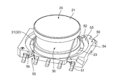
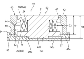
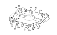
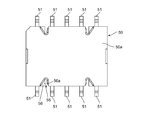
- FIG. 1 It is a perspective view which shows the structure of the magnetic element which concerns on one embodiment of this invention. It is a perspective view which shows the structure which removed the ring core among the magnetic elements of FIG. It is sectional drawing which shows the state which cut
- the magnetic element 10 of the present embodiment is a transformer, and includes a drum core 20, a coil 30, a ring core 40, and a base 50.
- the drum core 20 corresponds to the first core member.
- the drum core 20 includes an upper flange portion 21, a column base portion 22, and a lower flange portion 23.
- the planar shape of the upper collar part 21, the column base part 22, and the lower collar part 23 is provided in a circular shape.
- the upper collar portion 21 of the drum core 20 is provided to have a diameter equivalent to that of the lower collar portion 23.
- the upper collar part 21 and the lower collar part 23 are provided with the thickness dimension of the collar part equally.
- the coil 30 can be formed.
- the magnetic element 10 is a transformer
- the primary coil 30 ⁇ / b> A coil 30 located on the inner peripheral side
- the secondary coil 30 ⁇ / b> B on the outer peripheral side
- the coil 30 is wound around the winding frame 24.
- the coil 30 when it is not necessary to distinguish the primary coil 30A and the secondary coil 30B, they are simply referred to as the coil 30.
- a positioning projection 23b protrudes downward from the lower surface 23a side of the lower collar 23.
- the positioning projection 23b is a portion that fits into a recessed portion 58 of the base 50 described later, and the drum core 20 is positioned with respect to the base 50 by this fitting. For this reason, the drum core 20 can be accurately positioned with respect to the base 50, and the characteristics of the magnetic element 10 can be stabilized.
- the ring core 40 corresponds to the second core member.
- the ring core 40 is a core member formed in an annular shape when viewed from above, and the above-described drum core 20 is formed in an opening 41 thereof. Can be positioned.
- the ring core 40 is provided such that its height dimension Hr is smaller than the height dimension Hd of the drum core 20.
- the height dimension Hr may be greater than or equal to the height dimension Hd.
- the opening 41 has a radial dimension that is larger on the lower side than on the upper side. That is, in the ring core 40, the dimension in the radial direction of the core portion 42 is reduced as it goes downward from the middle portion in the height direction, and a gap portion 44 having a constant size from a predetermined position to the lower end is formed.
- a gap portion 44 having a constant size from a predetermined position to the lower end is formed.
- the ring core 40 is provided with a notch 43 from the bottom to the top.
- the notch 43 is a part for pulling out the terminal 32 of the coil 30 toward the terminal 51.
- the cutout 43 is arranged so as to face the side of the base 50 where the terminals 51 are arranged side by side (the short direction of the base 50).
- the drum core 20 and the ring core 40 are made of a magnetic material.
- the magnetic material for example, various ferrites such as nickel-based ferrite or manganese-based ferrite, permalloy, sendust, and the like can be used. is there.
- the base 50 is made of a non-magnetic material such as resin, and is formed by embedding a plurality of terminals 51. As shown in FIG. 5, the terminal 51 has a substrate connecting portion 51 a that protrudes downward from the lower surface 50 a of the base 50. Thus, the board connection portion 51a is provided in contact with the board when mounted on the mounting board.
- the base 50 includes a drum placement portion 52, a ring placement portion 53, an outer peripheral wall portion 54, and a recess portion 55 as other parts of the embedded terminal 51. And a protrusion 56.
- the drum placement portion 52 corresponds to the first placement portion, is a portion having the lowest height dimension on the upper surface side of the base 50, and is a portion on which the drum core 20 is placed.
- the 1st surrounding wall part 57 which is a boundary of the drum mounting part 52 and the ring mounting part 53 is provided so that a substantially circular arc may be made when it sees from upper direction.
- the radial dimension (corresponding to a radius) from the center of the drum mounting portion 52 to the first peripheral wall portion 57 is provided to be slightly larger than the radius of the lower surface 23a of the lower flange portion 23 of the drum core 20. ing.
- a recess 58 is provided at the center of the drum mounting portion 52. The positioning projection 23b of the drum core 20 is fitted into the recess 58, and the drum core 20 is positioned with respect to the base 50.
- the ring placement unit 53 corresponds to the second placement unit.
- the ring mounting portion 53 is located on the outer diameter side of the drum mounting portion 52 with the first peripheral wall portion 57 interposed therebetween, and is provided so as to protrude (position above) the drum mounting portion 52. ing.
- the ring placement portion 53 is a portion on which the ring core 40 is placed.
- the second peripheral wall portion 59 which is a boundary between the ring placement portion 53 and the outer peripheral wall portion 54, is provided so as to form a substantially circular arc when viewed from above.
- the radial dimension from the center of the drum mounting portion 52 to the second peripheral wall portion 59 is set so that the lower surface 40a side of the ring core 40 can be mounted on the ring mounting portion 53.
- the ring mounting portion 53 is provided in an arc shape, and is provided in a state where both end portions are present (having a finite length). Moreover, the both ends of the ring mounting part 53 are provided with a recessed part 55 and a protruding part 56 described later.
- the recessed part 55 is located in the both ends of the ring mounting part 53 as mentioned above, and the shape which notched the said base 50 along the transversal direction of the base 50 as shown in FIG. Is provided.
- there are a total of four indentations 55 because they are provided at both ends of a pair of ring mounting portions 53 having a substantially circumferential shape.
- the recessed portion 55 is a portion through which the terminal 32 of the coil 30 is passed, as will be described later.
- the shape of the recessed part 55 is provided in the substantially right triangle shape whose top part is R in what is shown in FIG.
- the shape of the recessed portion 55 is not limited to such a shape, and various shapes (for example, a polygonal shape such as a square shape, a circular shape, etc.) can be adopted.
- the number of the recessed portions 55 is not limited to four, and it is sufficient that there are at least two or more.
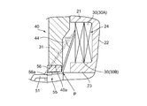
- the protrusion part 56 is provided so that the upper part of the dent part 55 may be covered.
- the projecting portion 56 is provided in a shape in which the end portion of the ring mounting portion 53 protrudes above the recessed portion 55.
- the protruding portion 56 is provided so that the lower surface 56 a is positioned above the upper end portion of the terminal 51.
- the terminal 32 of the coil 30 is positioned on the lower surface 56a of the protruding portion 56, the protruding portion 56 only needs to protrude above the recessed portion 55 by a corresponding amount.
- the protruding portion 56 protrudes so as to cover approximately half of the recessed portion 55.
- the conducting wire 31 is wound around the winding frame portion 24 of the drum core 20 by using a winding machine or the like or by manual work. Thereby, the primary coil 30A and the secondary coil 30B are formed. At this time, the terminals 32 of the primary coil 30A and the secondary coil 30B are kept pulled out.
- the terminal 32 of the coil 30 is guided to the outside of the ring core 40, and the terminal 32 is further inserted into the recessed portion 55.
- the terminal 32 is positioned on the lower surface 56 a of the protrusion 56.
- the terminal 32 of the coil 30 is made to reach the terminal 51, and the terminal 32 is bound to the terminal 51.
- the terminal 32 of the conducting wire 31 comes into a state where the bent portion P is formed by being bent in contact with the protruding portion 56.
- the terminal 32 may be attached and fixed in a state where both are electrically conducted by soldering.
- the cutout portion 43 of the ring core 40 is arranged so as to face the side where the terminals 51 are arranged, and the ring core 40 is placed on the ring placement portion 53.
- the bent portion P is formed in the terminal 32 due to the presence of the protruding portion 56, but at the same time, the terminal 32 enters the recessed portion 55. Therefore, the conducting wire 31 closer to the coil 30 than the bent portion P is brought closer to the center side of the drum core 20 (see the solid line and the two-dot chain line in FIG. 7). Therefore, it will be in the state which prevents that the ring core 40 and the conducting wire 31 interfere.
- an adhesive may be applied to the lower surface 40a side of the ring core 40.
- the terminal 32 of the coil 30 is positioned in the recess 55 and then positioned on the lower surface 56 a of the protrusion 56. No more going up. Therefore, it is possible to prevent the terminal 32 of the coil 30 from interfering when the ring core 40 is placed on the ring placement portion 53.
- the terminal 32 of the coil 30 enters the recess 55. Therefore, it is possible to position the bent portion P of the terminal 32 closer to the center side in the radial direction of the drum core 20 than in the case where the recessed portion 55 is not provided. For this reason, the lead wire 31 closer to the coil 30 than the bent portion P is brought closer to the center side of the drum core 20, so that the ring core 40 and the lead wire 31 can be prevented from interfering with each other. It is possible to effectively prevent the terminal 31 from interfering (the terminal 32 obstructs the placement of the ring core 40).
- the drum core 20 is provided with a positioning projection 23b that protrudes toward the base 50, and the base 50 is provided with a recess 58 into which the positioning projection 23b is fitted. For this reason, the drum core 20 can be accurately positioned with respect to the base 50 by fitting the positioning projection 23b into the recess 58. As a result, the characteristics of the magnetic element 10 can be stabilized.
- the ring core 40 has a gap 44 formed therein. For this reason, the terminal 32 of the coil 30 can be easily pulled out from the winding frame portion 24 to the recess portion 55 through the gap portion 44. Therefore, the terminal 32 of the coil 30 is easily entangled with the terminal 51 in a state where the terminal 32 is positioned by the protruding portion 56 of the recessed portion 55.
- the drum core 20 is used as the first core member and the ring core 40 is used as the second core member has been described.
- the first core member is not limited to the drum core 20
- the second core member is not limited to the ring core 40.
- a T-shaped core may be used as the first core member
- a pot-type core may be used as the second core member.
- the upper collar portion 21 and the lower collar portion 23 of the drum core 20 are provided with substantially the same diameter.
- the upper collar part may be formed with a larger diameter than the lower collar part, and conversely, the upper collar part may be formed with a smaller diameter than the lower collar part.
- a drum-shaped core may be formed by combining a T-shaped core and a disk-shaped core.
- the drum core 20 and the ring core 40 are provided in a circular shape when viewed from above.
- the drum core and the ring core are not limited to a circular shape when viewed from above, and various shapes can be adopted. Examples of various shapes include a polygonal shape such as a quadrangular shape, a hexagonal shape, and an octagonal shape, and an elliptical shape.
- the ring mounting portion 53 is formed on a flat surface.
- the ring core 40 may be configured to be positioned with respect to the base 50.
- the magnetic element is not limited to the transformer, and the present invention may be applied to a magnetic element (inductor, choke coil, filter, etc.) other than the transformer.
- the use of the magnetic element 10 in the above-described embodiment is not particularly limited, and can be used for various uses.
- the magnetic element of the present invention can be used in the field of electrical equipment.
Landscapes
- Engineering & Computer Science (AREA)
- Power Engineering (AREA)
- Microelectronics & Electronic Packaging (AREA)
- Coils Or Transformers For Communication (AREA)
Abstract
Description
以上のような構成を有する磁性素子10の組み付け方法について、以下に説明する。まず、ドラムコア20を、ベース50のドラム載置部52に載置する。このとき、位置決め突起23bが窪み部58に嵌り込む状態とする。なお、ドラムコア20のドラム載置部52への載置に際して、予め下鍔部23の下面23aに接着剤を塗布するようにしても良い。
以上のような構成の磁性素子10によれば、コイル30の端末32は、凹み部55に位置し、その後突出部56の下面56aに位置させられるので、当該端末32がリング載置部53の上に差し掛かることが無くなる。そのため、コイル30の端末32が、リングコア40をリング載置部53に載置する際に邪魔になるのを防止することが可能となる。
以上、本発明の一実施の形態に係る磁性素子10について説明したが、本発明はこれ以外にも種々変形可能となっている。以下、それについて述べる。
20…ドラムコア(第1のコア部材に対応)
21…上鍔部
22…柱脚部
23…下鍔部
23b…位置決め突起
30…コイル
31…導線
32…端末
40…リングコア(第2のコア部材に対応)
41…開口部
42…コア部分
44…隙間部
50…ベース
51…端子
52…ドラム載置部(第1載置部に対応)
53…リング載置部(第2載置部に対応)
54…外周壁部
55…凹み部
56…突出部
58…窪み部
Claims (4)
- 巻枠部を有する第1のコア部材と、
上記第1のコア部材の外周の全周に亘って対向配置される第2のコア部材と、
導線の巻回によって上記巻枠部に配置されるコイルと、
上記第1のコア部材が載置される第1載置部を有し、上記第1載置部よりも隆起して設けられ両端部の間に位置しかつ上記第2のコア部材が載置される第2載置部を有すると共に、複数の端子が側方から突出して設けられるベースと、
を具備し、さらに、
上記第2載置部の端部には、当該第2載置部から離間する向きに延伸する突出部が設けられると共に、この突出部は上記ベースの厚み寸法よりも小さく設けられ、
上記コイルの端末は上記突出部のうち上記第2のコア部材が載置される側とは反対側の裏面に位置させた後に、上記端子に絡げられる、
ことを特徴とする磁性素子。 - 請求項1記載の磁性素子において、
前記ベースのうち、前記第2載置部の端部には、当該ベースの反対側の側面に向かって窪んだ凹み部が設けられていて、
前記突出部は、前記第2のコア部材が載置される側から上記凹み部を覆う状態で設けられている、
ことを特徴とする磁性素子。 - 請求項1記載の磁性素子において、
前記第1のコア部材には、ベース側に向かって突出する位置決め突起が設けられると共に、前記ベースの第1載置部には上記位置決め突起が嵌り込む窪み部が設けられていることを特徴とする磁性素子。 - 請求項2記載の磁性素子において、
前記第2のコア部材は、前記第2載置部に載置される側となる下方側の開口部の内径寸法が上方側の内径寸法と比較して大きく形成される隙間部を有することを特徴とする磁性素子。
Priority Applications (2)
| Application Number | Priority Date | Filing Date | Title |
|---|---|---|---|
| CN201080005109.4A CN102292783B (zh) | 2009-02-03 | 2010-01-28 | 磁性元件 |
| US13/147,033 US8508322B2 (en) | 2009-02-03 | 2010-01-28 | Magnetic element |
Applications Claiming Priority (2)
| Application Number | Priority Date | Filing Date | Title |
|---|---|---|---|
| JP2009022666A JP5544721B2 (ja) | 2009-02-03 | 2009-02-03 | 磁性素子 |
| JP2009-022666 | 2009-02-03 |
Publications (1)
| Publication Number | Publication Date |
|---|---|
| WO2010089979A1 true WO2010089979A1 (ja) | 2010-08-12 |
Family
ID=42541890
Family Applications (1)
| Application Number | Title | Priority Date | Filing Date |
|---|---|---|---|
| PCT/JP2010/000492 Ceased WO2010089979A1 (ja) | 2009-02-03 | 2010-01-28 | 磁性素子 |
Country Status (4)
| Country | Link |
|---|---|
| US (1) | US8508322B2 (ja) |
| JP (1) | JP5544721B2 (ja) |
| CN (1) | CN102292783B (ja) |
| WO (1) | WO2010089979A1 (ja) |
Families Citing this family (16)
| Publication number | Priority date | Publication date | Assignee | Title |
|---|---|---|---|---|
| CN101681710A (zh) * | 2007-06-19 | 2010-03-24 | 胜美达集团株式会社 | 磁性元件及使用磁性元件的天线装置 |
| JP5516357B2 (ja) * | 2010-11-17 | 2014-06-11 | スミダコーポレーション株式会社 | 磁性素子 |
| JP6100999B2 (ja) * | 2012-01-18 | 2017-03-22 | 株式会社小糸製作所 | 電力供給装置の製造方法 |
| GB2501104A (en) * | 2012-04-12 | 2013-10-16 | Eltek As | Compact, efficient common mode inductor for a power converter system |
| KR101792279B1 (ko) * | 2012-12-04 | 2017-11-01 | 삼성전기주식회사 | 인덕터 및 인덕터 제조 방법 |
| CN103489567B (zh) * | 2013-09-13 | 2017-06-06 | 华为技术有限公司 | 共模电感 |
| JP6398302B2 (ja) * | 2014-05-12 | 2018-10-03 | スミダコーポレーション株式会社 | コイル部品および電子回路 |
| CN104319079A (zh) * | 2014-10-13 | 2015-01-28 | 东莞建冠塑胶电子有限公司 | 一种电感元件 |
| CN104377023A (zh) * | 2014-11-27 | 2015-02-25 | 广州金升阳科技有限公司 | 一种电流互感器 |
| KR102010256B1 (ko) * | 2016-05-24 | 2019-08-13 | 주식회사 아모그린텍 | 코일부품 |
| JP6577918B2 (ja) | 2016-08-02 | 2019-09-18 | 太陽誘電株式会社 | コイル部品 |
| WO2018117595A1 (en) * | 2016-12-20 | 2018-06-28 | Lg Innotek Co., Ltd. | Magnetic core, coil component, and electronic component including same |
| US11450461B2 (en) * | 2019-03-22 | 2022-09-20 | Cyntec Co., Ltd. | Electronic device |
| CN111540575B (zh) * | 2020-06-08 | 2025-06-17 | 昆山玛冀电子有限公司 | 磁性元件及其制备方法 |
| US12255002B2 (en) * | 2020-11-24 | 2025-03-18 | Steering Solutions Ip Holding Corporation | High current surface mount toroid inductor |
| CN120913991A (zh) * | 2024-05-06 | 2025-11-07 | 台达电子企业管理(上海)有限公司 | 磁性元件及其制作方法 |
Citations (5)
| Publication number | Priority date | Publication date | Assignee | Title |
|---|---|---|---|---|
| JPH01163306U (ja) * | 1988-05-07 | 1989-11-14 | ||
| JPH058914U (ja) * | 1991-07-16 | 1993-02-05 | テイーデイーケイ株式会社 | コイル部品 |
| JPH10303035A (ja) * | 1997-04-30 | 1998-11-13 | Tokyo Parts Ind Co Ltd | 面実装コイル |
| JPH11224819A (ja) * | 1998-02-04 | 1999-08-17 | Fuji Elelctrochem Co Ltd | トランス用巻線部品 |
| JP2008004740A (ja) * | 2006-06-22 | 2008-01-10 | Sumida Corporation | 磁性素子 |
Family Cites Families (3)
| Publication number | Priority date | Publication date | Assignee | Title |
|---|---|---|---|---|
| JPS625618A (ja) * | 1985-07-02 | 1987-01-12 | Matsushita Electric Ind Co Ltd | チツプ・インダクタ |
| JP3497276B2 (ja) | 1994-07-20 | 2004-02-16 | 松下電器産業株式会社 | インダクタンス素子とその製造方法 |
| JP2007194282A (ja) * | 2006-01-17 | 2007-08-02 | Sumida Corporation | コイル部品 |
-
2009
- 2009-02-03 JP JP2009022666A patent/JP5544721B2/ja not_active Expired - Fee Related
-
2010
- 2010-01-28 US US13/147,033 patent/US8508322B2/en not_active Expired - Fee Related
- 2010-01-28 CN CN201080005109.4A patent/CN102292783B/zh not_active Expired - Fee Related
- 2010-01-28 WO PCT/JP2010/000492 patent/WO2010089979A1/ja not_active Ceased
Patent Citations (5)
| Publication number | Priority date | Publication date | Assignee | Title |
|---|---|---|---|---|
| JPH01163306U (ja) * | 1988-05-07 | 1989-11-14 | ||
| JPH058914U (ja) * | 1991-07-16 | 1993-02-05 | テイーデイーケイ株式会社 | コイル部品 |
| JPH10303035A (ja) * | 1997-04-30 | 1998-11-13 | Tokyo Parts Ind Co Ltd | 面実装コイル |
| JPH11224819A (ja) * | 1998-02-04 | 1999-08-17 | Fuji Elelctrochem Co Ltd | トランス用巻線部品 |
| JP2008004740A (ja) * | 2006-06-22 | 2008-01-10 | Sumida Corporation | 磁性素子 |
Also Published As
| Publication number | Publication date |
|---|---|
| US20110291783A1 (en) | 2011-12-01 |
| JP5544721B2 (ja) | 2014-07-09 |
| JP2010182733A (ja) | 2010-08-19 |
| CN102292783B (zh) | 2013-08-07 |
| CN102292783A (zh) | 2011-12-21 |
| US8508322B2 (en) | 2013-08-13 |
Similar Documents
| Publication | Publication Date | Title |
|---|---|---|
| JP5544721B2 (ja) | 磁性素子 | |
| JP5388141B2 (ja) | トランスフォーマー及びこれを備える平板ディスプレイ装置 | |
| CN103632819B (zh) | 磁性元件 | |
| TWI395238B (zh) | Magnetic parts | |
| KR101153580B1 (ko) | 라인 필터 및 이를 구비하는 평판 디스플레이 장치 | |
| US7573364B2 (en) | Coil unit | |
| KR101475677B1 (ko) | 코일 부품 및 이를 포함하는 전원공급장치 | |
| JP5516357B2 (ja) | 磁性素子 | |
| JP4586879B2 (ja) | コイル部品 | |
| WO2020162334A1 (ja) | コイル部品 | |
| US20060006970A1 (en) | Inductance device | |
| CN103426612A (zh) | 表面安装电感器 | |
| JP6413639B2 (ja) | 磁性素子 | |
| JP2003257741A (ja) | インダクタンス素子 | |
| CN1933051B (zh) | 电感器 | |
| JP2010021479A (ja) | トランス | |
| JP6405695B2 (ja) | トランスボビンおよびトランス | |
| JP4825693B2 (ja) | コイル部品 | |
| JP6606830B2 (ja) | 磁性素子 | |
| JP4786744B2 (ja) | 複合磁性素子 | |
| JP4987657B2 (ja) | 小型昇圧トランス | |
| JP2013182927A (ja) | コイル部品 | |
| JP5187248B2 (ja) | 巻線部品 | |
| JP2006294872A (ja) | コイルボビン及びそのコイルボビンを用いた電気機器 | |
| JPH0794342A (ja) | 面実装型コイル |
Legal Events
| Date | Code | Title | Description |
|---|---|---|---|
| WWE | Wipo information: entry into national phase |
Ref document number: 201080005109.4 Country of ref document: CN |
|
| 121 | Ep: the epo has been informed by wipo that ep was designated in this application |
Ref document number: 10738322 Country of ref document: EP Kind code of ref document: A1 |
|
| WWE | Wipo information: entry into national phase |
Ref document number: 13147033 Country of ref document: US |
|
| NENP | Non-entry into the national phase |
Ref country code: DE |
|
| 122 | Ep: pct application non-entry in european phase |
Ref document number: 10738322 Country of ref document: EP Kind code of ref document: A1 |