WO2010087162A1 - カラー画像処理方法、カラー画像処理装置および記録媒体 - Google Patents
カラー画像処理方法、カラー画像処理装置および記録媒体 Download PDFInfo
- Publication number
- WO2010087162A1 WO2010087162A1 PCT/JP2010/000458 JP2010000458W WO2010087162A1 WO 2010087162 A1 WO2010087162 A1 WO 2010087162A1 JP 2010000458 W JP2010000458 W JP 2010000458W WO 2010087162 A1 WO2010087162 A1 WO 2010087162A1
- Authority
- WO
- WIPO (PCT)
- Prior art keywords
- albedo
- color
- surface reflectance
- correction
- information
- Prior art date
Links
Images


Classifications
-
- H—ELECTRICITY
- H04—ELECTRIC COMMUNICATION TECHNIQUE
- H04N—PICTORIAL COMMUNICATION, e.g. TELEVISION
- H04N1/00—Scanning, transmission or reproduction of documents or the like, e.g. facsimile transmission; Details thereof
- H04N1/46—Colour picture communication systems
- H04N1/56—Processing of colour picture signals
- H04N1/60—Colour correction or control
- H04N1/62—Retouching, i.e. modification of isolated colours only or in isolated picture areas only
- H04N1/628—Memory colours, e.g. skin or sky
Definitions
- the present invention relates to image processing of a color image, and in particular, a color image processing method for improving the texture by realizing color correction of an object in a color image actually captured by a color image device and desired color reproduction of the object.
- the present invention relates to a color image processing apparatus and a color image processing program.
- a preferred color is obtained by bringing the color of a specific object (skin color, green vegetation, blue sky, etc.) in the color image close to the memory color of the object.
- skin color, green vegetation, blue sky, etc. skin color, green vegetation, blue sky, etc.
- Patent Document 1 discloses a technique related to color correction of a color image.
- a representative color is extracted from an object region in an image, the representative color is compared with a preset central color of correction, RGB correction parameters are determined, and correction of each pixel is performed with the central color.
- the correction strength of the correction parameter is controlled according to the distance.
- the RGB value which is the color information of each pixel of the color image, is converted to hue, saturation, and brightness, and the distance in the color space between the color and the correction center color is calculated, and according to the distance
- a method has been proposed in which the color of an object is intensively corrected by adjusting the correction intensity.
- RGB correction amount is calculated for each pixel according to the distance from the correction center color.
- a correction parameter corresponding to the distance from the correction center color is added to or subtracted from the RGB value of each pixel in almost the entire face area.
- Patent Document 2 discloses a technique related to detection of a face area in an input image.
- Patent Literature 3 when color correction is performed on spectral color image data, the spectral color is converted to a lower-dimensional color space than the original dimension, and color correction is performed within the lower-dimensional color space.
- a color correction apparatus and method for generating a spectral light of a different dimension when color correction is performed on spectral color image data, the spectral color is converted to a lower-dimensional color space than the original dimension, and color correction is performed within the lower-dimensional color space.
- Patent Document 4 discloses a technique for converting an original color space into a color of a target color space while matching the appearance of colors between color systems having different reference whites. Specifically, the spectral distribution characteristic of the original reference white is restored from the color temperature of the original reference white that is the reference white of the original color space, and the target reference white is converted from the color temperature of the target reference white that is the reference white of the target color space. Restore spectral distribution characteristics. Then, the surface reflectance of the arbitrary color in the original color space is restored using the tristimulus value of the arbitrary color, the light distribution characteristic of the original reference white, and the human color matching function. Further, tristimulus values that are colors in the target color space are obtained based on the restored surface reflectance, the restored spectral distribution characteristics of the target reference white, and the human color matching function.
- Patent Document 5 discloses a technique for automatically performing good white correction on an important subject in a natural image taken under various lighting environments. Specifically, the body surface color of the specific object is extracted, and the color correction parameter optimum for the extracted representative color is set. This makes it possible to automatically perform color correction on important subjects in natural images taken under various lighting environments. Note that the inventions of Patent Documents 3, 4, and 5 have completely different configurations from the present invention described later.
- Patent Document 6 proposes a method of modeling human skin reflexes for rendering facial images.
- a face is scanned with a 3D scanner to obtain a three-dimensional shape.
- a plurality of face images illuminated in different illumination directions from different viewpoints are acquired.
- the total reflectance and the normal map are estimated using the surface scan data and the image data.
- the subsurface reflectance is scanned using an optical fiber spectrometer to obtain a translucency map.
- the total reflectance is separated into two components: subsurface scattering and (specular) surface reflectance.
- Patent Documents 1 and 2 and Non-Patent Documents 1 and 2 are incorporated herein by reference.
- the following is an analysis of the related art according to the present invention.
- a color image processing method using three color attributes such as RGB, hue, saturation, and brightness of color image data may reduce the texture of the original object. There is.
- the reason for this is that when correcting the color of an object in the image brightly, the color component (for example, red) that normally has a high pixel value is saturated and the other color components (green, blue) are saturated. A phenomenon occurs in which correction parameters are added or subtracted. When this process is performed on the entire area of the object, the dispersion of color information or pixel values in the area of the object is reduced, and the apparent texture in the area of the object is reduced.
- the color component for example, red
- the other color components green, blue
- Patent Document 6 proposes a human skin reflection model for rendering a facial image, but requires an optical fiber spectrometer as a special measurement device. For this reason, it is difficult to apply color correction to general color image processing.
- An object of the present invention is to provide a color image processing method, a color image processing apparatus, and a color image for realizing a desired color reproduction of a predetermined object in a color image photographed by a color image device and improving the texture. It is to provide a processing program.
- One aspect of the color image processing method detects an object region based on an input image, acquires color information and three-dimensional information of the object region, and obtains the color information and the three-dimensional information. Based on the above, the surface reflection component and the body reflection component of the object region are restored, the surface reflection component and the body reflection component are removed from the color information, an albedo is calculated, and the color information and the albedo are used. Recovering the surface reflectance, calculating a corrected albedo obtained by correcting the albedo using the surface reflectance, and adding the body reflection component and the surface reflection component to the corrected albedo to reproduce the color of the object region And an output image is generated.
- an image information acquisition unit that detects an object region based on an input image and acquires color information and three-dimensional information of the object region; Based on the information and the three-dimensional information, a reflection information restoration unit for restoring the surface reflection component and the body reflection component of the object region, and an albedo obtained by removing the surface reflection component and the body reflection component from the color information are calculated.
- An albedo calculation unit that restores surface reflectance using the color information and the albedo, calculates an albedo correction processing unit that corrects the albedo using the surface reflectance, and the correction albedo
- a reproduction color calculation unit that adds a body reflection component and the surface reflection component to calculate a reproduction color of the object region, and generates an output image.
- the program detects a target area based on an input image on the computer, and the color information of the target area and 3 From the color information, an image information acquisition procedure for acquiring dimensional information, a reflection information restoration procedure for restoring a surface reflection component and a body reflection component of the object region based on the color information and the three-dimensional information, and the color information
- An albedo calculation procedure for calculating the albedo by removing the surface reflection component and the body reflection component, and a correction in which the surface reflectance is restored using the color information and the albedo, and the albedo is corrected using the surface reflectance.
- An albedo correction processing procedure for calculating an albedo, and adding the body reflection component and the surface reflection component to the correction albedo; Calculating a reproduced color of the band, and reproduced color calculation procedure for generating the output image, thereby executing.
- the present invention it is possible to realize a desired color reproduction of a predetermined object in a color image taken by a color image device and improve the texture.
- FIG. 1 is a block diagram illustrating a configuration example of a color image processing apparatus according to an embodiment of the present invention. It is a flowchart explaining the example of a procedure of the color image processing method of Embodiment 1 of this invention. It is a figure explaining the process which calculates
- the present invention when correcting the color of the specific object in the input image, first, the three-dimensional shape (also referred to as three-dimensional information) of the specific object restored from the input image and the illumination geometric condition ( The surface reflection component (highlight) generated on the specific object and the complete scattering component including the shadow are calculated. Next, using the color information (albedo) from which the influence of the surface reflection component and the complete scattering component including the shadow (hereinafter referred to as body reflection component) is removed from the color information of the specific object, the specific object is The surface reflectance to be expressed is accurately restored, and correction is performed so as to approach the more preferable reference surface reflectance of the object set in advance. Then, the reproduced color of the specific object is calculated using the corrected surface reflectance, surface reflection component, and body reflection component. As a result, the reproduced color after color correction of the specific object looks close to nature and is expressed in a more preferable color.
- FIG. 1 shows a processing flow of a color image processing method according to an embodiment of the present invention.
- an input image and information about the input image are acquired to the color image processing apparatus (image information acquisition process). Specifically, an input image is input, and a specific object is specified from the input image. By specifying the specific object, a region (object region) for correcting the albedo is detected. Further, the three-dimensional shape and color information (color of the object area) of the specific object are acquired.
- the reflection information of the specific object is restored (reflection information restoration process). Specifically, the illumination geometric condition is restored based on the three-dimensional shape.
- the surface reflection component and the body reflection component are restored using the color information, the three-dimensional shape, and the geometric conditions of illumination.
- the surface reflection component is removed from the pixel value of each pixel of the input image, and the component represented by the product of the albedo and the body reflection component is separated.
- the body reflection component is a component including shadow information.
- the albedo of the specific object is calculated (albedo calculation process). Specifically, the albedo is calculated by dividing the pixel value from which the surface reflection component is removed by the body reflection component.
- the calculated surface reflectance is brought close to the reference surface reflectance.
- the albedo is corrected.
- the surface reflection component and the body reflection component are added to the corrected albedo, and the reproduction color of the specific object is calculated (reproduction color calculation processing).
- an object region detected from a specific object is composed of a plurality of pixels.
- Each pixel has color information, and the color information is sometimes referred to as a pixel value.
- the color information includes at least a surface reflection component and a body reflection component and includes other color information.
- the specific object and the object area are not particularly distinguished.
- Albedo is color information obtained by removing the surface reflection component and the body reflection component from the color information of the specific object. That is, the color information is obtained by removing the surface reflection component (light) and the body reflection component (shadow) from the image information of the specific object (color information acquired from the input image). Therefore, it can also be said to be color information of the specific object itself.
- the color information of the object area is expressed as a product of an albedo and a body reflection component plus a surface reflection component.
- the body reflection component includes shadow information.
- the reference surface reflectance is a surface reflectance set in advance according to the specific object. The reference surface reflectance will be described later.
- FIG. 2 shows a configuration example of a color image processing apparatus according to an embodiment of the present invention.
- the color image processing apparatus 100 includes an image information acquisition unit 110, a reflection information restoration unit 120, an albedo calculation unit 130, an albedo correction processing unit 140, and a reproduction color calculation unit 150.
- the image information acquisition unit 110 inputs an input image from the outside, specifies a specific target based on the input image, and detects a target region of the specific target. Further, the image information acquisition unit 110 acquires color information and a three-dimensional shape of the object area.
- the reflection information restoration unit 120 restores the shadow information, the surface reflection component, and the body reflection component of the object area based on the color information and the three-dimensional shape. Specifically, the reflection information restoration unit 120 restores illumination geometric information (illumination irradiance) using the three-dimensional information, and uses the three-dimensional shape and the illumination geometric information to reflect the surface reflection component and the body reflection. Restore ingredients. Details will be described later.
- the albedo calculation unit 130 calculates the albedo by subtracting the surface reflection component from the color information and further dividing by the body reflection component.
- the albedo correction processing unit 140 restores the surface reflectance using the color information and the albedo, and calculates a corrected albedo obtained by correcting the albedo using the surface reflectance.
- the albedo correction processing unit 140 is configured to include a spectral distribution restoration unit 141 and an albedo correction unit 142.
- the spectral distribution restoration unit 141 restores the illumination spectral distribution using the color information of the object region.
- the albedo correction unit 142 restores the surface reflectance of the object region using the restored spectral distribution of illumination and the albedo. Then, the corrected albedo is calculated by correcting the albedo based on the restored surface reflectance.
- the reproduction color calculation unit 150 adds the surface reflection component and the body reflection component to the correction albedo to calculate the reproduction color of the object area, and generates an output image using the calculated reproduction color. A description will be given below according to the embodiment.
- FIG. 3 is a flowchart for explaining the color image processing method according to the first embodiment of the present invention.
- the color system of the image is the RGB color system. That is, the color of the image is represented by a combination of R (red), G (green), and B (blue), and is represented as color information RGB.
- the present invention it is needless to say that the present invention can be applied to a color system other than RGB.
- the reproducible color is recalculated in each pixel of the object area in the color image.
- the specific object is different from the individual, that is, even if there is an individual difference, the rough color information and texture are universal, so it is specified as an object assumed from the characteristics obtained from the color image There is no particular limitation as long as it is possible.
- the image information acquisition unit 110 automatically detects a specific object from the input image (step S1). At this time, the image information acquisition unit 110 acquires the color information of the object area in the detected specific object. As shown in FIG. 4, a specific object is detected from the input color image using color information, texture, and the like. Hereinafter, a case where the specific object is a human face will be described. When the specific object is a human face, a face region is detected using shape features such as eyes, nose and mouth.
- the face detection method described in Non-Patent Document 2 can be used.
- This method is a face detection method that combines an image-based type and a feature-based type for eye detection using generalized learning vector quantization.
- a method for detecting a face area from an input image a method described in Patent Document 2 for detecting eyes from an image can be used. That is, it is easy to estimate the face area if the eye position is detected from the input image.
- the above two methods generally perform face detection using monochrome information. However, by adding a determination as to whether the detected face area is a skin color, It is also possible to improve the detection accuracy.
- a method using an image histogram described in Patent Document 1 can be used.
- the face detection method is not limited to the above two methods, and another method may be used.
- the object to be automatically detected from an arbitrarily given input image is a face, but other objects than the face can also be handled.
- the object is automatically detected by comparing the pre-registered visual feature information of the object region with the visual feature information of the image data. Can be used.
- the spectral distribution restoration unit 141 restores the illumination color information (illumination spectral distribution) when the input image is captured from the color information (color of the object region) of the specific object in the input image (Ste S2).
- the color information of the illumination that would have been used when the input image was taken that is, the spectral distribution characteristics of the illumination To restore.
- the color information RGB of the object area is acquired, and tristimulus values XYZ of the XYZ color system are obtained based on the acquired color information RGB.
- the spectral distribution is restored from the tristimulus values XYZ of the object region in the input image and the surface reflectance of the object.
- FIG. 4 is a diagram for explaining an outline of processing for automatically detecting a target area in an input image and obtaining color information.
- the color information of the object area any one color such as the average color of the pixels existing in the area occupied by the object, the center color (median), or the most frequent color (mode) is used. Can be used as the color information of the object area.
- the color information RGB of the object area is acquired, and tristimulus values XYZ of the XYZ color system are obtained based on the acquired color information RGB.
- the color information RGB of the input image the chromaticity and white chromaticity of the RGB phosphors of RGB are designated in advance, and the relationship between the RGB data and the emission intensity of the display device is assumed to be linear. .
- the relationship between the RGB of the input image and the tristimulus values XYZ is expressed by the following equation (1).
- RX is a 3 ⁇ 3 transformation matrix. This conversion matrix RX can be uniquely calculated if the chromaticity of the RGB phosphor and the chromaticity of white are determined.
- Non-Patent Document 2 As a method for calculating the transformation matrix RX, for example, the method described in Non-Patent Document 2 can be used. Moreover, if the color image display apparatus currently used is an sRGB (Standard RGB) display, a conversion matrix defined by the International Electrotechnical Commission (IEC) may be used. An XYZ value of black may be further added as an offset term to the expression (1).
- sRGB Standard RGB
- IEC International Electrotechnical Commission
- the spectral distribution restoration unit 141 calculates the spectral distribution of illumination.
- the spectral distribution of illumination is color information of illumination when an input image is taken.
- photography the input image is the illumination (light source) which irradiates the target object in an input image.
- an observation equation for restoring the spectral distribution is generated from the tristimulus values XYZ of the object region in the image obtained by Expression (1) and the surface reflectance of the object.
- the tristimulus value XYZ indicating the color of the object area based on the XYZ color system is expressed by the following formula (from the surface reflectance of the object area, the spectral distribution of illumination illuminating the object, and the color matching function of human vision: 2).
- ⁇ is the wavelength
- I ( ⁇ ) is the spectral distribution of illumination
- R ( ⁇ ) is the surface reflectance of the object region.
- x ( ⁇ ), y ( ⁇ ), and z ( ⁇ ) are known functions of color matching functions. Integration is performed in the wavelength region of visible light.
- the equation (2) is an observation equation of the spectral distributions I ( ⁇ ) and R ( ⁇ ) of unknown illumination. It becomes.
- I ( ⁇ ) and R ( ⁇ ) which are continuous functions related to the wavelength, cannot be calculated from Equation (2).
- Equation (2) becomes an observation equation of only I ( ⁇ ).
- the surface reflectance of the Japanese face region having the average skin color illustrated in FIG. 5 may be used as R ( ⁇ ) in the equation (2). it can.
- FIG. 5 is a graph showing the surface reflectance of a Japanese face region having an average skin color. The horizontal axis represents wavelength (nm) and the vertical axis represents surface reflectance (%).
- the surface reflectance of the object region selected as having the average or representative color of the surface reflectance obtained by measuring the object multiple times is obtained in advance.
- R ( ⁇ ) the surface reflectance of the object region is acquired in advance and stored in the color image processing apparatus 100 (for example, in the albedo correction processing unit 140).
- I ( ⁇ ) cannot be calculated analytically as it is. This is because the illumination spectral distribution I ( ⁇ ) is inherently represented by an infinite dimensional waveform in the visible light region.
- I ( ⁇ ) can be expressed with a small number of parameters.
- CIE daylight is a light source for colorimetry specified by the CIE (International Commission on Illumination) by a relative spectral distribution, and is known to be well approximated by an average and a linear sum of two principal components.
- FIG. 6 is a graph showing the average of CIE daylight and the first and second principal component vectors. The horizontal axis represents the wavelength (nm), and the vertical axis represents the spectral distribution spectrum power at each wavelength of the illumination or light source. From this, the spectral distribution I ( ⁇ ) of illumination can be expressed as follows.
- Substituting I (lambda) of the formula (3) into equation (2) becomes a binary simultaneous linear equations for the unknown characteristic parameters a 1 and a 2 representing the color of the illumination, easily calculate a 1, a 2 I can do it.
- the characteristic parameters a 1 and a 2 representing the color of the obtained illumination By substituting the characteristic parameters a 1 and a 2 representing the color of the obtained illumination into the equation (3), the spectral distribution I ( ⁇ ) of the illumination is obtained.
- the illumination spectral distribution obtained by the above procedure is the illumination spectral distribution I ( ⁇ ) when the input image is taken.
- the image information acquisition unit 110 restores the three-dimensional shape of the specific object in the image (step S3).
- the specific object is described as a human face, and in this case, the technique of the following document (hereinafter referred to as non-patent document 3) can be used.
- a three-dimensional shape of a face in a 2D image is estimated using a face model having average 3D information about a human face shape in advance.
- Non-Patent Document 3 Satoshi Ishiyama, “Verification of non-frontal face images by posture conversion using a general 3D face model”, IEICE, 2007 General Conference, D-12-085, 2007, p. 201.
- the above is a 3D shape restoration method in the case of specializing a human face as a specific object.
- the specific object has a generally universal shape even if there is an individual difference
- Non-Patent Document 3 is By expanding to a specific object, an approximate three-dimensional shape can be restored from the input image.
- the apparent color of a specific object in the input image is affected by the geometric conditions between the lighting in the scene and the object. That is, when the illumination and the geometric condition of the object change, the apparent color of the object also changes.
- non-patent documents 4, 5, and 6 describe non-patent documents 4, 5, and 6.
- Non-Patent Document 4 R. Basri and D. Jacobs, “Lambertian Reflectance and Linear Subspaces”, Proc. IEEE Intl. Conf. Computer Vision 01, pp.383-389, 2001.
- Non-Patent Document 5 R. Ramamoorthi and P. Hanrahan, “An efficient representation for irradiance environment maps”, [online], Proc. ACM SIGGRAPH 01, pp.
- Non-Patent Document 6 Ravi Ramamoorthi and Pat Hanrahan: "On the relationship between radiance and irradiance: determining the illumination from images of a convex Lambertian object", J. Opt. Soc. Am. A / Vol. 18, No. 10 / October 2001.
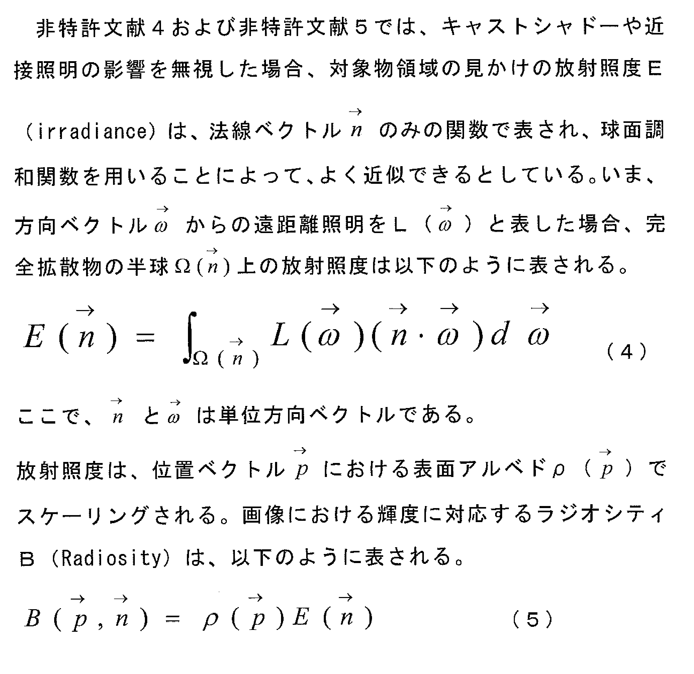
- the lighting conditions are estimated from the observed values (irradiance irradiance) on the Lambertian surface.
- the illumination is a non-negative function on the surface of the convex object under the assumption that the influence of cast shadow and proximity illumination can be ignored.
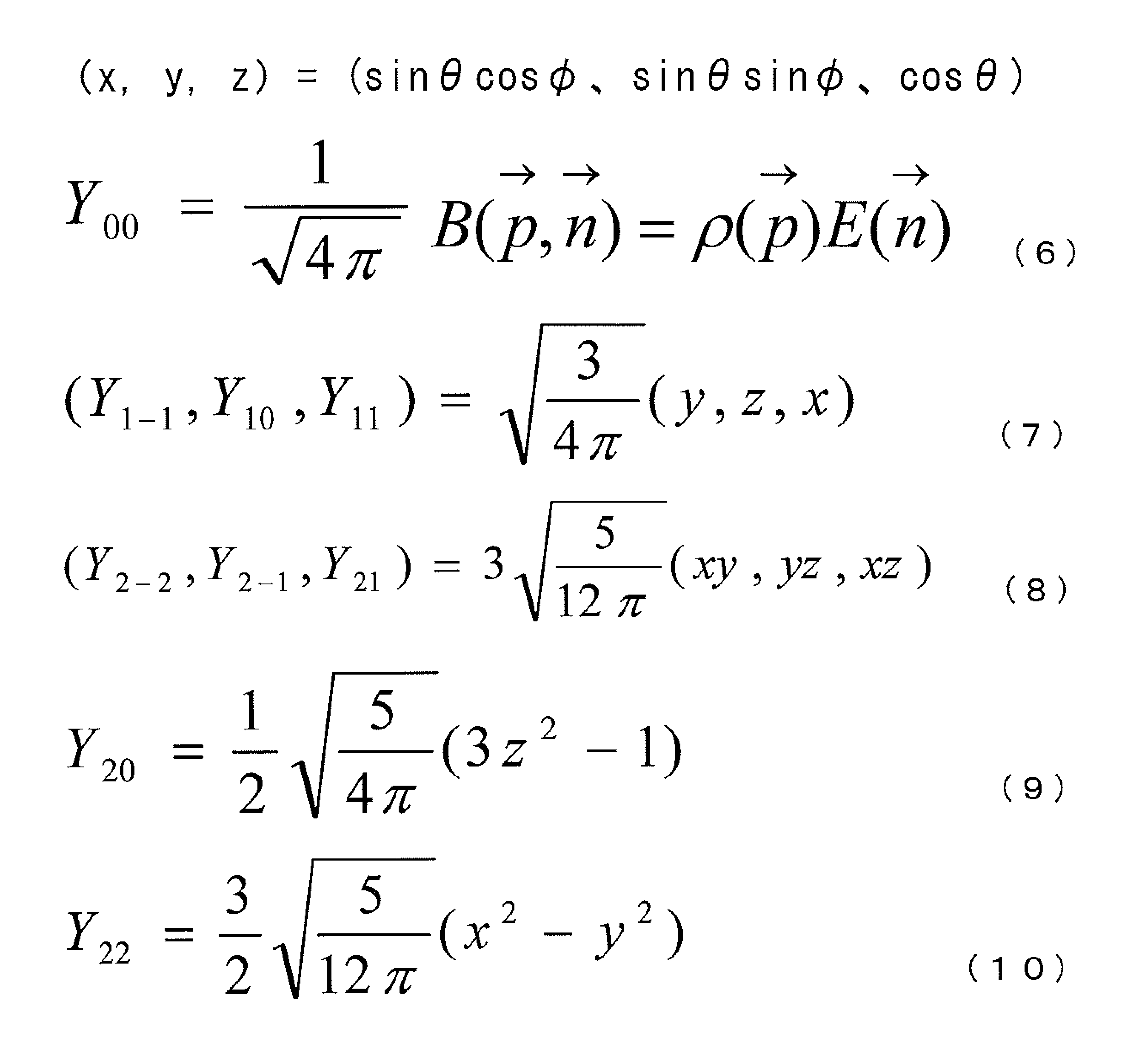
- this function is expressed using a spherical harmonic function.
- the spherical harmonic Y lm (l ⁇ 0, ⁇ l ⁇ m ⁇ 1) is similar to the Fourier basis for a straight line or a circle and on the sphere.
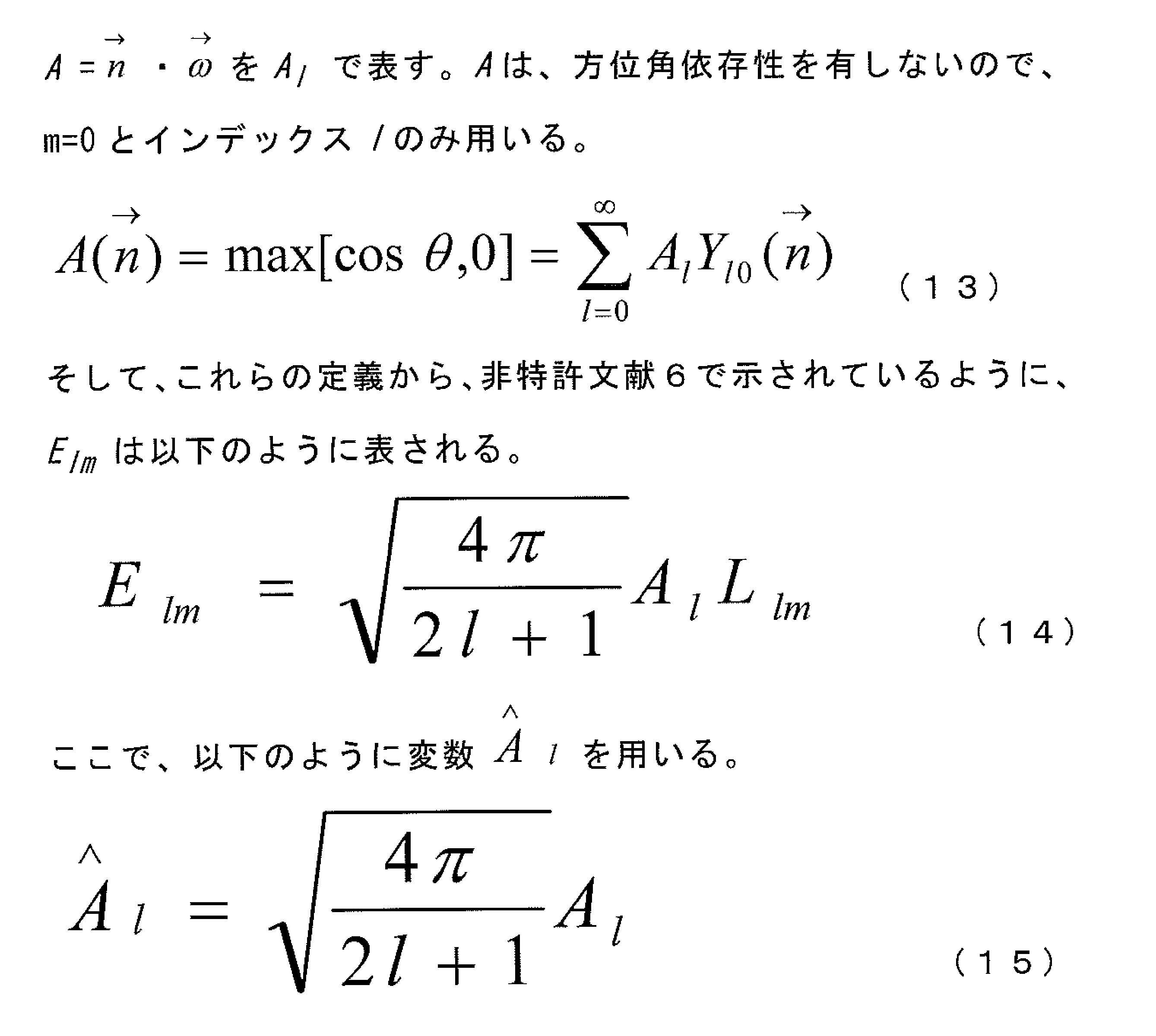
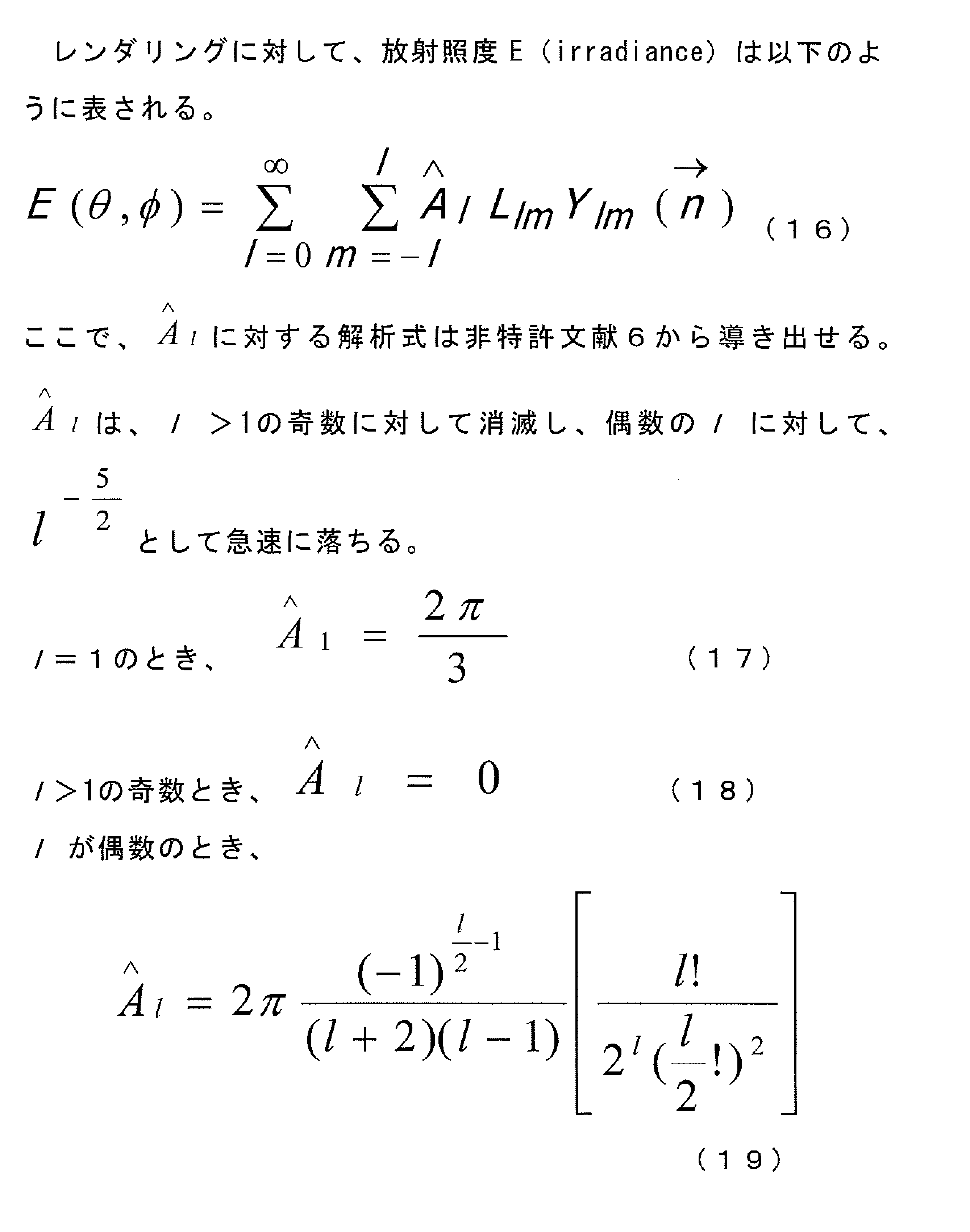
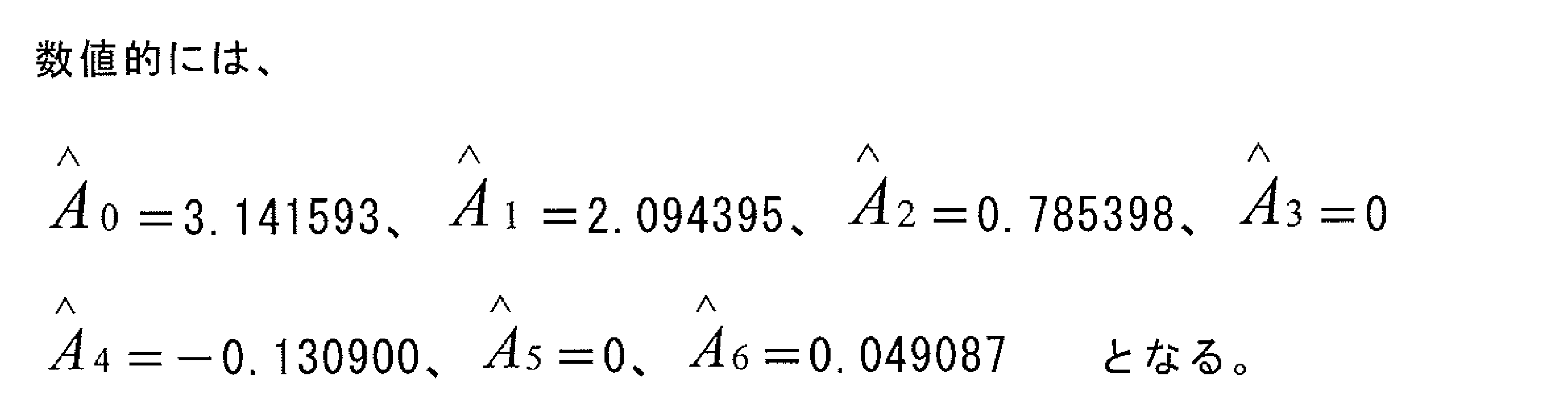
- the irradiance E in each pixel of the specific object represented by the equation (16) is obtained. That is, it means that the illumination geometric condition for the specific object in the input image can be restored.
- the irradiance E is regarded as a geometric condition.
- the reflection information restoration unit 120 restores (calculates) the surface reflection component and the body reflection component of the specific object in the input image (step S5).
- the reflectance of an object depends on the geometric conditions of incident light and emitted light.
- this reflection characteristic is expressed as a bidirectional reflectance distribution function BRDF (Bidirectional Reflectance Distribution Function).
- the BRDF is often composed of two components, a surface reflection component (Secular component) and a body reflection component (Body reflection component).
- the surface reflection component is a component that reflects on the surface of the skin.
- the body component is a component of light once incident on the inside of the skin and the light diffused in the body once again diverges through the skin.
- the irradiance at each pixel of the specific object is calculated by spherical harmony as shown in step S4. . Since perfect diffusion is assumed, this irradiance E can be regarded as a diffuse reflection component (or body reflection component) DR (Diffuse Reflection) of a specific object.
- DR diffuse Reflection
- the irradiance E is calculated for each color channel (for example, R, G, B, etc.) and is expressed as Ei. i represents each color channel.
- the diffuse reflection component body reflection component
- DRi diffuse Reflecti.
- the diffuse reflection component (body reflection component) is calculated on the assumption that the specific object is a Lambertian, but actually includes a surface reflection component rather than a diffuse reflection component (body reflection component). . That is, it can be said that the pixel value of each color channel of the input image represents the apparent brightness in the color channel including the diffuse reflection component (body reflection component) and the surface reflection component.
- the diffuse reflection component (body reflection component) is calculated by the least square method or the like in the object region, and the irradiance does not necessarily match the pixel value. The difference that occurs here can be considered to be the surface reflection component. Accordingly, the surface reflection component SPi of each color channel of a certain pixel in the specific object region is calculated by the following equation.
- Ii a pixel value of a certain pixel in the specific object region of the input image
- i a color channel (for example, R, G, B, etc.).
- the body reflection component BRi of a certain pixel in the specific object region of the input image is obtained by subtracting the surface reflection component SPi from the pixel value Ii of the image.
- Min (x, y) is a function that outputs the minimum value of x and y.
- the luminance (brightness) of the diffuse reflection component (body reflection component) DRi is the shadow information (Shading) of the object area.
- the shadow information represents the luminance of the diffuse reflection component (body reflection component) DRi of a certain pixel in the region of the specific object of the input image, and can be calculated by Expression (1). If the tristimulus value Y (Y component of the tristimulus value) calculated by the equation (1) is used as the shadow information generated from the three-dimensional shape of the object and the geometry of the illumination, the albedo calculates the shadow information from the color information. It may be defined that the color information is obtained by removing.
- the albedo correction processing unit 140 restores the surface reflectance R ( ⁇ ) from the albedo of each pixel and the spectral distribution of illumination in the specific object in the input image (step S7).
- the input image is an RGB color system image.
- the tristimulus values XYZ are calculated from the RGB values of each pixel represented by the albedo ADi in the region of the specific object according to the equation (1), and are substituted into the left side of the equation (2).
- the equation (2) is obtained at a pixel having the region of the specific object.
- the surface reflectance R ( ⁇ ) is also represented by an infinite dimensional waveform in the visible light region, as is the case with the spectral distribution of illumination, and this can be analytically calculated from the observation equation (2). Absent. Therefore, the surface reflectance of the specific object is also modeled using a finite-dimensional linear model expressed by a weighted sum of low-dimensional basis vectors.
- FIG. 7 is an example of basis vectors obtained by principal component analysis of the surface reflectance of an object.
- the horizontal axis represents the wavelength (nm), and the vertical axis represents the spectral distribution spectrum power at each wavelength of the illumination or light source. Note that a basis vector obtained by collecting a large number of surface reflectances of a specific object and analyzing them by principal component analysis may be used.
- step S8 using the reference surface reflectance of the object region, the reproduction surface reflectance of each pixel in the object in the input image is calculated, and the corrected albedo is calculated (step S8).
- the surface reflectance of each pixel in the target object in the input image calculated in step S7 is corrected based on the reference surface reflectance set so that the desired color of the target region can be reproduced.
- the reference surface reflectance of the object region is a surface reflectance that is set so that a desired color of the object region can be reproduced. More specifically, in a color image obtained by photographing the object under standard illumination, the surface reflectance is such that the object is good and has a preferable color (lightness, saturation, hue). That is.
- This reference surface reflectance depends on human subjectivity and cannot be uniquely defined, but can be obtained in advance by performing a subjective evaluation experiment. For example, the image quality is evaluated by changing the color of the object region in the image in various ways using an image processing tool. And the above-mentioned step S2 and step S3 are applied about the image when it is judged that it is most preferable in evaluation. Thereby, the reference surface reflectance of each pixel in the object region can be obtained.
- the reference surface reflectance three or more colors are selected in advance from the object region, and correspond to the average color, the center color (median), and the most frequent color (mode) of the selected colors.
- the surface reflectance may be the reference surface reflectance of the object area, and Rref ( ⁇ ).
- the lightest color, darkest color, highest saturation color, lowest saturation color in the target area, and the color distribution in the target area are analyzed, and the colors located at both ends of the hue are analyzed.
- the reference surface reflectance Rref ( ⁇ ) of the object region may be used.
- the surface reflectance for the color in the region may be set as the reference surface reflectivity of the target region as Rref ( ⁇ ). For example, when the object is a face, a cheek, a corner of the eye, a forehead, and the like are given as feature regions.
- An average color of pixels existing in a certain range in these characteristic areas may be obtained, and a surface reflectance for the average color may be calculated to obtain a reference surface reflectance Rref ( ⁇ ) of the object area.
- Rref a reference surface reflectance of the object region
- the reproduction surface reflectance Rmd ( ⁇ ) is calculated by correcting the surface reflectance R ( ⁇ ) of each pixel in the specific object in the input image by using the reference surface reflectance Rref ( ⁇ ). . That is, the reproduction surface reflectance Rmd ( ⁇ ) for reproducing a preferable color is calculated using Rref ( ⁇ ) that is a reference surface reflectance for reproducing the color of the object region satisfactorily.
- Reproduction surface reflectance Rmd An example of the calculation method of ( ⁇ ) is shown below.
- Rmd ( ⁇ ) ⁇ ⁇ R ( ⁇ ) + (1- ⁇ ) ⁇ Rref ( ⁇ ) (26)
- ⁇ is a real number between zero and 1.0 (0 ⁇ ⁇ ⁇ 1.0).
- the surface reflectance is obtained for the color of the pixel corresponding to the average color, the median color (median), or the most frequent color (mode) of the specific object in the input image, and this is expressed as Ravg ( ⁇ ).
- Ravg the average color
- mode the most frequent color
- ⁇ the reference surface reflectance
- a function F ( ⁇ ) relating to the wavelength ⁇ is defined as follows.
- F ( ⁇ ) Rref ( ⁇ ) / Ravg ( ⁇ ) (27)
- the surface reflectance R ( ⁇ ) of each pixel in the specific object in the input image is corrected as follows to calculate a reproduction surface reflectance Rmd ( ⁇ ) that reproduces a preferable color.
- Rmd ( ⁇ ) ⁇ ⁇ F ( ⁇ ) ⁇ R ( ⁇ ) + (1- ⁇ ) ⁇ R ( ⁇ ) (28)
- ⁇ is a real number between zero and 1.0 (0 ⁇ ⁇ ⁇ 1.0).
- the average color, center color (median), and most frequent color (mode) of a specific object area the brightest, darkest, most saturated, and most saturated color in the object area Low color, color distribution in the object area, and colors located at both ends of the hue, or if the shape feature is available in the object in the input image, the color in that area, etc.
- Corresponding reference surface reflectivity For each, colors having the same properties in the object region in the input image are obtained, and the surface reflectance is obtained for those colors.
- the first reference surface reflectance Rref (1, ⁇ ) is the surface reflectance with respect to the average color of the object region in the image determined to be most preferable as described above,
- the surface reflectance R (1, ⁇ ) for the average color in the object region is obtained.
- the average color in the object area in the input image is corrected to the center color in the object area in the image when it is determined to be preferable.
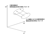
- the distribution of the characteristic parameter in the region of the specific object in the input image is maintained at the distribution of the characteristic parameter in the reference surface reflectance that brings about the desired color reproduction (change in color dispersion ( (Bias and reduction) can be suppressed, and the texture of the color after correction is not impaired.
- the color dispersion is adjusted by adjusting the distribution of the characteristic parameter in the reference surface reflectance. It is also possible to improve the deterioration of the texture due to too large.
- Applying the correction matrix of Equation (29) to the characteristic parameter b i (i 1 to 3) that constitutes the surface reflectance of each pixel in the target object in the input image to calculate the corrected characteristic parameter; By substituting into the equation (24), it is possible to obtain the reproduced surface reflectance after correction of each pixel in the object in the input image.
- the corrected color of each pixel in the object in the input image is calculated by substituting the spectral distribution of illumination and the reproduced surface reflectance into the right side of Equation (2) to obtain tristimulus values X′Y′Z ′.
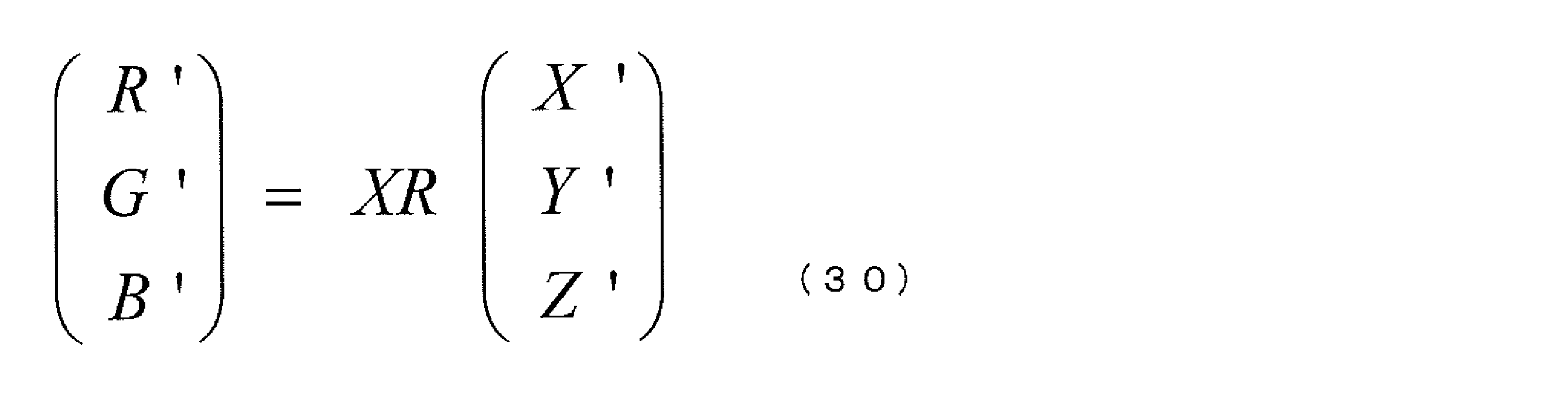
- the corrected albedo ADi ′ (i represents the color channel) is calculated. In the case of RGB, calculation is performed as follows.
- XR is an inverse matrix of the matrix RX of Equation (1), and is a known value.
- the corrected color of each pixel in the object in the input image is calculated using the corrected albedo, shadow information (brightness of diffuse reflection component), and surface reflection component (step S9).
- the corrected albedo ADi ′ is multiplied by the luminance of the diffuse reflection component to calculate the body reflection component BRi ′.
- BRi ' ADi' x Y (31)
- Y is the luminance of the diffuse reflection component DRi, that is, the Y component of the tristimulus value obtained by Equation (1).
- the pixel value Ii ′ after color correction is obtained by adding the surface reflection component SPi to the body reflection component BRi.
- Ii ' Bri' + Spi (32)
- the device-dependent color of the input image and the output image is RGB
- the device-dependent color other than RGB such as CMY or CMYK
- the device-dependent color and the device-independent color are three. If the correspondence with the stimulus value XYZ is obtained, the color correction method of the present invention can be applied to images other than RGB.
- the device-dependent color means a color space that depends on the output destination device.
- step S2 the process of restoring the spectral distribution of illumination (illumination color information) in step S2 only needs to be performed in a stage prior to step S7, and is not necessarily performed in the order of the processes in FIG. May be.
- FIG. 9 is a diagram illustrating a configuration example of the color image processing apparatus according to the first embodiment of the present invention.
- the color image processing apparatus 101 is an apparatus that performs color correction on the input image 1 and outputs an output image 2.
- the color image processing apparatus 101 includes an object region detection unit 3, a spectral distribution restoration unit (illumination spectral distribution restoration unit) 4, a representative surface reflectance storage memory (a representative surface reflectance storage memory of the object region) 5, A three-dimensional information restoration unit (three-dimensional information restoration unit of the object region) 6, a reflection information restoration unit (surface reflection component and body reflection component restoration unit of the object region) 7, and an albedo calculation unit (object region An albedo calculation unit) 8, a surface reflectance restoration unit (surface reflectance restoration unit of the object region) 9, a correction albedo calculation unit (albedo correction unit by surface reflectance correction) 10, and a reference surface reflectance storage memory ( A reference surface reflectance storage memory 11 for the object region and a reproduction color calculation unit (reproduction color calculation unit for the object region) 12 are provided.
- the target area detection unit 3 analyzes the input image 1, detects a specific target assumed in advance, and outputs information indicating the target area in the detected specific target.
- the information indicating the object area includes color information of the object area.
- the target area detection unit 3 obtains the color information of the target area by the procedure for acquiring the color information of the target area described in the first half of step S2.
- the object to be detected from the input image 1 is such that the color and shape characteristics of the object region can be limited to some extent, such as a human face, as described above. About a detection method, what is necessary is just to follow an above-described method. If the target object is not detected from the input image 1, the input image 1 is output as the output image 2.
- the spectral distribution restoration unit 4 restores the spectral distribution of the illumination in the input image using the color information in the target area and the representative surface reflectance of the target area.
- the object area is detected by the object area detection unit 3.
- the spectral distribution restoration unit 4 performs the spectral distribution (illumination color information) of the illumination in the target area by the procedure of restoring the spectral distribution described in the second half of step S2 in FIG. 3 from the target area.
- the representative surface reflectance of the object area is read from the representative surface reflectance storage memory 5 of the object area.
- the spectral distribution restoration unit 4 restores the spectral distribution of illumination according to the process described in step S2, using the color information in the object area and the representative surface reflectance of the object area. That is, the spectral distribution restoration unit 4 executes a process corresponding to step S2 in FIG.
- the representative surface reflectance storage memory 5 of the object area stores a typical surface reflectance of the object area (representative surface reflectance of the object area). A preset value is used for the representative surface reflectance of the object region.
- the 3D information restoring unit 6 restores the 3D shape of the object area detected by the object area detecting unit 3. In the three-dimensional information restoration unit 6, a process corresponding to step S3 described above is executed.
- the reflection information restoration unit 7 first restores the irradiance E (illumination geometric condition) of the object using the three-dimensional shape (that is, the normal vector) of the object region. Then, the surface reflection component and the body reflection component are restored using the color information, the three-dimensional shape, and the irradiance E.
- the three-dimensional shape is calculated by the three-dimensional information restoration unit 6.
- the three-dimensional shape of the object region is a normal vector as described in step S4 of FIG.
- the processing described in step S4 described above is executed as the calculation of irradiance. Further, the reflection information restoration unit 7 restores (calculates) the surface reflection component and the body reflection component in the object region according to the processing method described in step S5 above.
- the albedo calculation unit 8 calculates the brightness of the body reflection component DRi obtained by the reflection information restoration unit 7, that is, albedo that is color information from which the shadow information is removed. The calculation follows the processing procedure described in step S6 above.
- the surface reflectance restoring unit 9 restores the surface reflectance of each pixel in the object area according to the above method from the restored spectral distribution of illumination and the albedo of the object area.
- a process corresponding to step S7 of FIG. 3 described above is executed.
- the correction albedo calculation unit 10 uses the reference surface reflectance of the object area stored in the reference surface reflectance storage memory 11 to correct the surface reflectance of each pixel in the restored object area according to the above method. And calculate the reproducible surface reflectance. Then, a corrected albedo (corrected albedo) is calculated from the spectral distribution of illumination and the reproduced surface reflectance. In the correction albedo calculation unit 10, a process corresponding to step S8 of FIG. 3 described above is executed.
- the reference surface reflectance storage memory 11 stores the reference surface reflectance of the object area.
- the reference surface reflectance storage memory 11 preferably stores reference surface reflectances of three or more object regions. By using a plurality of reference surface reflectances, the color information of the specific object itself can be made closer.
- the reproduction color calculation unit 12 uses the albedo of each pixel in the corrected object region, the luminance of the diffuse reflection component (body reflection component), that is, the shadow information, and the surface reflection component, to detect the object in the input image.
- the corrected color of each pixel is calculated and output as an output image.
- a process corresponding to step S9 in FIG. 3 described above is executed.
- the color image processing apparatus 101 can be related as follows.
- the image information acquisition unit 110 includes an object region detection unit 3 and a three-dimensional information restoration unit 6.
- the reflection information restoration unit 120 corresponds to the reflection information restoration unit 7.
- the albedo calculation unit 130 corresponds to the albedo calculation unit 8.
- the spectral distribution restoration unit 141 includes the spectral distribution restoration unit 4 and the representative surface reflectance storage memory 5 of the object region.
- the albedo correction unit 142 includes a surface reflectance restoration unit 9, a correction albedo calculation unit 10, and a reference surface reflectance storage memory 11.
- the reproduction color calculation unit 150 corresponds to the reproduction color calculation unit 12. Note that the configuration of the color image processing apparatus shown in FIG. 2 or FIG. 9 is an example, and other configurations may be adopted as long as the apparatus implements the same function.
- the color image processing apparatus 101 can be realized by a computer, and each component constituting the color image processing apparatus, that is, the object region detection unit 3, the spectral distribution restoration unit 4, and the representative surface of the object region.
- the reproduction color calculation part 12 is realizable as a program for making the central processing unit (CPU) of a computer implement
- the fact that each component constituting the color image processing apparatus can be realized by a computer and can be realized as a program is not limited to the first embodiment, but is also the same in other embodiments.
- FIG. 10 is a flowchart showing a color image processing method according to the second embodiment of the present invention.
- the two processes performed in step S7 and step S8 (FIG. 3) of the color image processing method of the first embodiment are combined. Specifically, a process of restoring the surface reflectance of each pixel in the object in the input image (step S7), and a process of correcting the restored surface reflectance and calculating a corrected albedo (step S8). ) And a correction formula based on linear calculation.
- This is a color image processing method that provides a correction result equivalent to that of the color image processing method of the first embodiment. Since the processing from step S1 to step S6 and step S9 in FIG. 10 is the same as the processing in the first embodiment, description thereof will be omitted, and step S10 will be described using the configuration example shown in FIG.
- the matrix to be corrected is calculated using the method for calculating the surface reflectance in the object region described in step S7. Specifically, in step S10, a calculation formula based on linear conversion that gives the same result as the calculation result of the reproduced color after correction performed in step S9 is constructed.
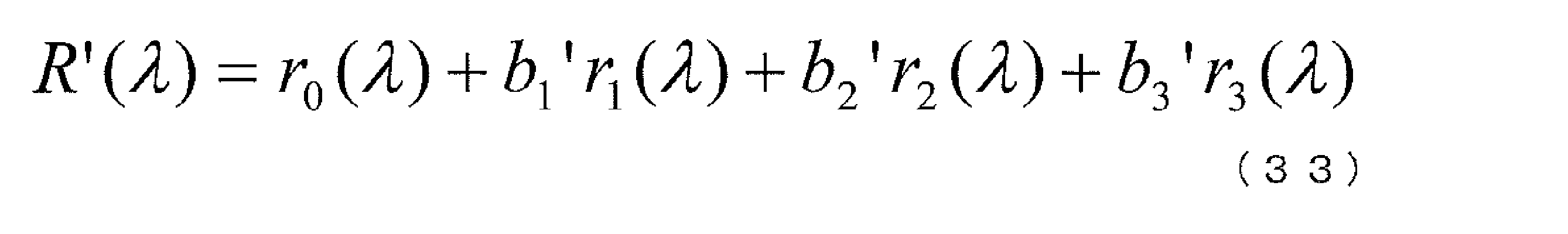
- the corrected surface reflectance R ′ ( ⁇ ) is expressed by Expression (33).
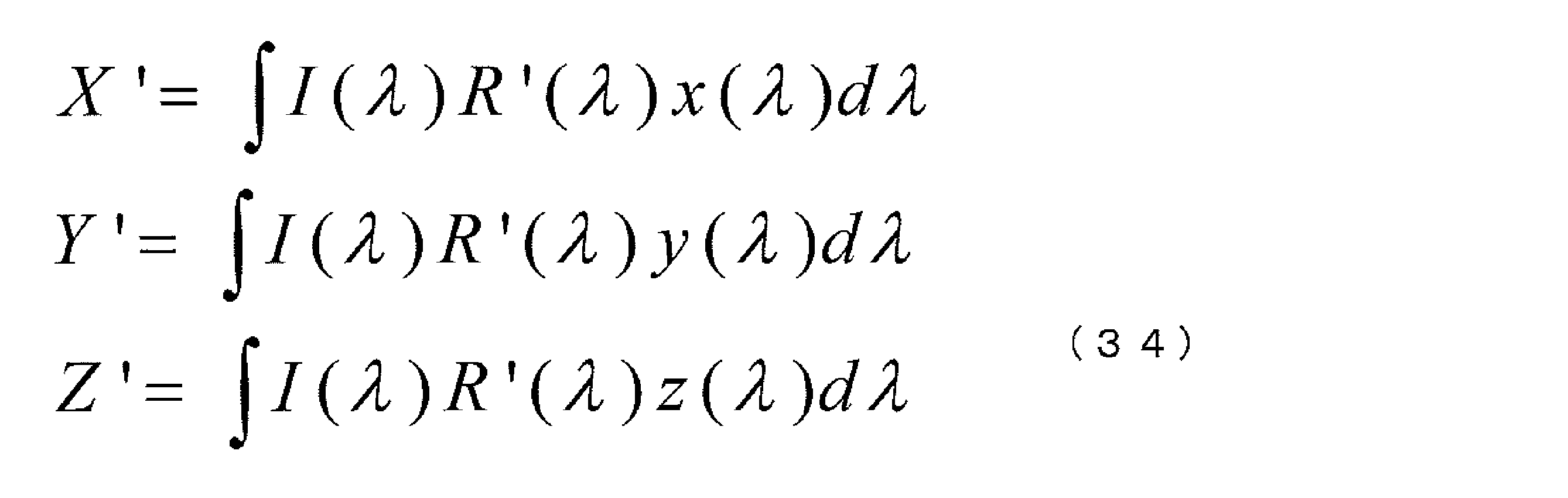
- the corrected tristimulus values X′Y′Z ′ of the object area are expressed as follows.
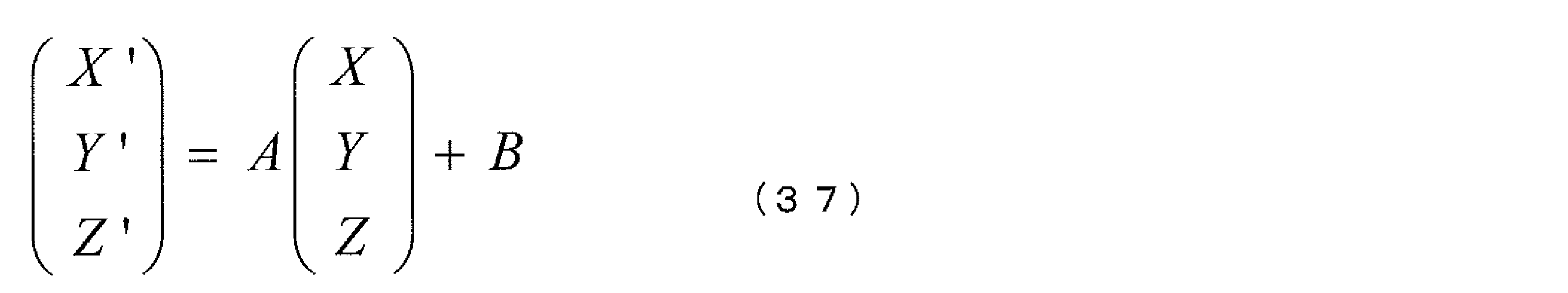
- Expression (34) is expressed as follows from Expression (25) and Expression (29).
- Equation (36) can then be summarized as Equation (37).
- the matrix A is a 3 ⁇ 3 matrix represented by the following equation (38)
- the matrix B is a 3 ⁇ 1 matrix represented by the following equation (39), both of which are constant matrices. It becomes.
- formula (37) which is a formula for correcting color information
- tristimulus values XYZ are calculated for all pixels in the object region in the input image
- tristimulus values after correction are calculated using formula (37).
- X'Y'Z ' is calculated.
- R′G′B ′ after correction that is, the albedo after correction is obtained by using linear transformation. In this way, the processing time can be increased by replacing the correction formula based on one linear calculation.
- FIG. 11 is a block diagram showing the configuration of Embodiment 2 of the color image processing apparatus according to the present invention.
- the color image processing apparatus 102 according to this embodiment is an apparatus that performs color correction on an input image 1 and outputs an output image 2.
- the color image processing apparatus 102 includes an object region detection unit 3, a spectral distribution restoration unit 4, a representative surface reflectance storage memory 5 for the object region, a three-dimensional information restoration unit 6, a reflection information restoration unit 7, An albedo calculation unit 8, an albedo correction unit 13, a reference surface reflectance storage memory 11, and a reproduction color calculation unit 12 are provided.
- the color image processing apparatus 102 is obtained by replacing the surface reflectance restoration unit 9 and the correction albedo calculation unit 10 of the color image processing apparatus 101 with an albedo correction unit 13. Therefore, only the albedo correction unit 13 will be described.
- the albedo correction unit 13 creates a correction formula for correcting the color of the object area represented by the formula (37). Then, the albedo correction unit 13 calculates the corrected albedo for the pixels in the object region by color correction according to Expression (37). Specifically, the albedo correction unit 13 restores the surface reflectance of the object region using the illumination spectral distribution and the albedo, and corrects the albedo using the surface reflectance in the creation of the correction formula. Create a correction formula. The albedo correction unit 13 corrects the surface reflectance using the reference surface reflectance to calculate the reproduced surface reflectance, and creates a correction formula using the reproduced surface reflectance. The reference surface reflectance is stored in the reference surface reflectance storage memory 11.
- the color image processing method and apparatus of each of the above embodiments can be realized using a computer.
- Each process of the color image processing method and apparatus can be realized by a combination of two or more of software, hardware, and firmware.
- the program program instruction group
- the program causes a computer to execute at least the following procedure.
- the program is loaded into the memory of the computer, and each instruction is executed under the control of the CPU.
- A An image information acquisition procedure for inputting an input image, detecting an object region based on the input image, and acquiring color information and a three-dimensional shape of the object region. This procedure corresponds to the image information acquisition unit 110 in FIG.
- B A reflection information restoration procedure for restoring the surface reflection component and the body reflection component of the object area based on the color information and the three-dimensional shape. This procedure corresponds to the reflection information restoration unit 120 in FIG.
- C An albedo calculation procedure for calculating an albedo obtained by subtracting the surface reflection component and the body reflection component from the color information. This procedure corresponds to the albedo calculation unit 130 of FIG.
- the albedo correction processing procedure may be specifically realized by the following procedure.
- F Spectral distribution restoration procedure for restoring the spectral distribution of illumination using color information.
- G An albedo correction procedure that uses the spectral distribution of illumination and the albedo to restore the surface reflectance of the object region, corrects the albedo based on the restored surface reflectance, and calculates a corrected albedo.
- the albedo correction procedure calculates the reproduced surface reflectance by correcting the surface reflectance using the reference surface reflectance corresponding to the object region previously stored in the reference surface reflectance storage memory, The albedo is corrected using the reproduced surface reflectance.
- the reference surface reflectance storage memory preferably stores three or more reference surface reflectances. In this case, the albedo correction procedure corrects the surface reflectivity using three or more reference surface reflectivities.
- the spectral distribution restoration procedure restores using the representative surface reflectance corresponding to the preset object region in addition to the color information.
- a correction expression for correcting the albedo may be created, and the correction albedo may be calculated by matrix conversion using the correction expression.
- Each procedure described above is an example of a procedure realized by a program, and is not limited to these. Also, some of the plurality of procedures can be realized by hardware or firmware.
- the program can be provided by being recorded on a recording medium, or can be provided by being transmitted via the Internet or another communication medium.
- the storage medium includes, for example, a flexible disk, a hard disk, a magnetic disk, a magneto-optical disk, a CD-ROM, a DVD, a ROM cartridge, a battery-backed RAM memory cartridge, a flash memory cartridge, and a nonvolatile RAM cartridge.
- the communication medium includes a wired communication medium such as a telephone line, a wireless communication medium such as a microwave line, and the like.
- a desired color reproduction of the specific object region is realized, It is possible to prevent the texture from deteriorating and maintain or improve the texture.
- the problem that the texture of an original object is lowered in color image processing using three color attributes such as RGB, hue, saturation, and brightness of color image data is solved.
- a measuring device such as an optical fiber spectrometer is not required, an easier method using only an input image can be realized.
- the present invention can be applied to a function for realizing color correction in a color image input / output device. Further, the present invention can be applied as color correction software or utility for an arbitrary color image by adopting a program that operates in a computer system.
Abstract
Description
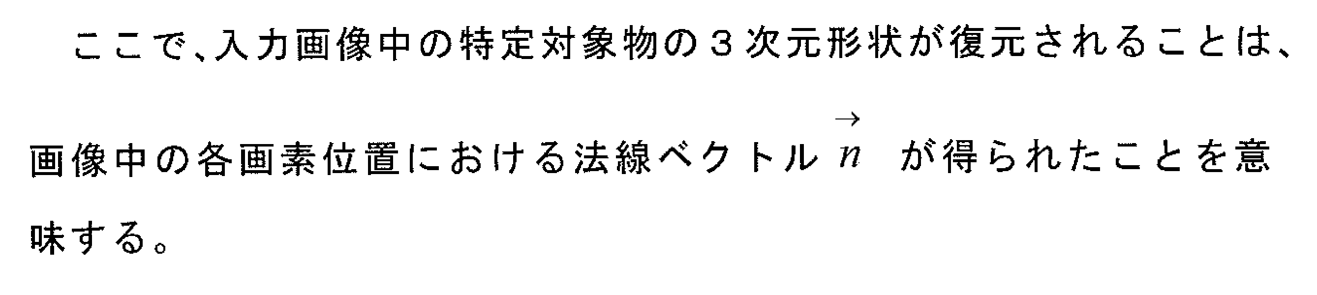
I.まず、カラー画像処理装置へ入力画像および入力画像に関する情報を取得する(画像情報取得処理)。具体的には、入力画像が入力され、入力画像から特定対象物が特定される。特定対象物が特定されることによって、アルベドを補正する領域(対象物領域)が検出される。また、特定対象物の3次元形状と色情報(対象物領域の色)が取得される。
II.次に、特定対象物の反射情報を復元する(反射情報復元処理)。具体的には、3次元形状に基づいて、照明の幾何条件が復元される。続いて、色情報、3次元形状及び照明の幾何条件を用いて、表面反射成分、及びボディー反射成分が復元される。このとき、入力画像の各画素の画素値から表面反射成分が除かれ、アルベドとボディー反射成分の積で表わされる成分が分離される。ここで、ボディー反射成分は陰影情報を含む成分である。
III.特定対象物のアルベドを計算する(アルベド計算処理)。具体的には、表面反射成分が除かれた画素値を、ボディー反射成分で割ることでアルベドを算出する。
IV.アルベドを補正する(アルベド補正処理)。具体的には、特定対象物の色情報とアルベドとを用いて表面反射率を算出する。そして、算出した表面反射率を参照表面反射率に近づける。これにより、アルベドを補正する。
V.補正されたアルベドへ表面反射成分とボディー反射成分とを付加し、特定対象物の再現色を算出する(再現色算出処理)。
また、以降の説明では、特定対象物と対象物領域とは特に区別しない。
アルベドは、特定対象物の色情報から表面反射成分とボディー反射成分とを除いた色情報である。すなわち、特定対象物の画像情報(入力画像から取得した色情報)から、表面反射成分(てかり)とボディー反射成分(影)を取り除いた色情報である。したがって、特定対象物そのものの色情報ともいえる。
対象物領域の色情報は、アルベドとボディー反射成分の積に、表面反射成分を付加したものとして表わされる。ボディー反射成分には陰影情報が含まれている。
参照表面反射率は、予め特定対象物に応じて設定された表面反射率である。参照表面反射率については後述する。
画像情報取得部110は、入力画像を外部から入力し、入力画像に基づいて、特定対象物を特定し、特定対象物の対象物領域を検出する。また、画像情報取得部110は、対象物領域の色情報と3次元形状とを取得する。
アルベド計算部130は、色情報から表面反射成分を引き、さらにボディー反射成分で割ることでアルベドを算出する。
再現色算出部150は、補正アルベドへ表面反射成分とボディー反射成分とを付加して対象物領域の再現色を算出し、算出した再現色を用いて出力画像を生成する。
以下実施形態に即して説明する。
まず、本発明の実施形態1のカラー画像処理方法について、図面を用いて処理の流れを説明する。ここでは、図2に示したカラー画像処理装置100の構成例を用いて説明する。
図3は、本発明の実施形態1のカラー画像処理方法を説明するためのフローチャートである。なお、ここでの説明の便宜上、画像の表色系は、RGB表色系であるものとする。すなわち、画像の色は、R(赤)、G(緑)、B(青)の組み合わせで表されるものとし、色情報RGBと表記するものとする。なお、本発明において、RGB以外の表色系にも適用可能であることは勿論である。
図4に示したように、入力されたカラー画像中から特定対象物を、色情報、テクスチャなどを用いて検出する。以下では、特定対象物を人間の顔とした場合について説明する。特定対象物を人間の顔とした場合には、目、鼻、口などの形状特徴を利用して顔領域を検出する。
また、入力画像から顔領域を検出する方法として、特許文献2に記載された、画像中から目を検出する方法を用いることができる。つまり、入力画像中から、目の位置が検出されれば、顔領域を推定することは容易である。
ここでは、カラー画像中の対象物領域の色情報、対象物が有する表面反射特性を利用して、入力画像を撮影した際に用いたであろう照明の色情報、すなわち、照明の分光分布特性を復元する。具体的には、対象物領域の色情報RGBを取得し、取得した色情報RGBに基づいて、XYZ表色系の三刺激値XYZを求める。そして、入力画像中の対象物領域の三刺激値XYZと対象物が有する表面反射率とから、分光分布を復元する。
図4は、入力画像中の対象物領域を自動検出し、色情報を求める処理の概略を説明する図である。なお、対象物領域の色情報として、対象物が占める領域内に存在する画素の平均色、中央色(メジアン)、最頻色(モード)など、いずれか一つの色を対象物領域の色情報として利用することができる。
以下では、入力画像の色情報RGBに関して、このRGBのRGB蛍光体の色度および白色の色度はあらかじめ指定されており、RGBデータと表示機器の発光強度の関係が線形であるものとして説明する。
この場合、入力画像のRGBと三刺激値XYZとの関係は、以下の式(1)で表される。

この変換行列RXは、RGBの蛍光体の色度と白色の色度が決まれば一意に計算できる。
XYZ表色系に基づく対象物領域の色を示す三刺激値XYZは、対象物領域の表面反射率、その対象物を照射する照明の分光分布および人間視覚の等色関数から、以下の式(2)で表現される。

いま、式(1)で計算された三刺激値XYZを式(2)の左辺に代入すると、式(2)は、未知である照明の分光分布I(λ)およびR(λ)の観測方程式となる。
しかし、現状では、波長に関する連続関数であるI(λ)およびR(λ)を、式(2)から計算することはできない。
例えば、対象物を日本人の顔とした場合には、図5に例示する平均的な肌色を有する日本人の顔領域の表面反射率を、式(2)のR(λ)として用いることができる。図5は、平均的な肌色を有する日本人の顔領域の表面反射率を示すグラフである。横軸は波長(nm)、縦軸は、表面反射率(%)を表す。
照明の分光分布I(λ)の観測方程式である式(2)から、このままでは、I(λ)を解析的に計算することは出来ない。これは、本来、照明の分光分布I(λ)は、可視光領域において無限次元の波形で表されるためである。しかし、I(λ)が少ないパラメータで表現できれば、この問題は解決される。
図6は、CIE昼光の平均および第1、第2主成分ベクトルを示すグラフである。横軸は波長(nm)、縦軸は照明や光源の各波長における分光分布スペクトルパワーを表している。
このことから、照明の分光分布I(λ)を以下のように表すことができる。
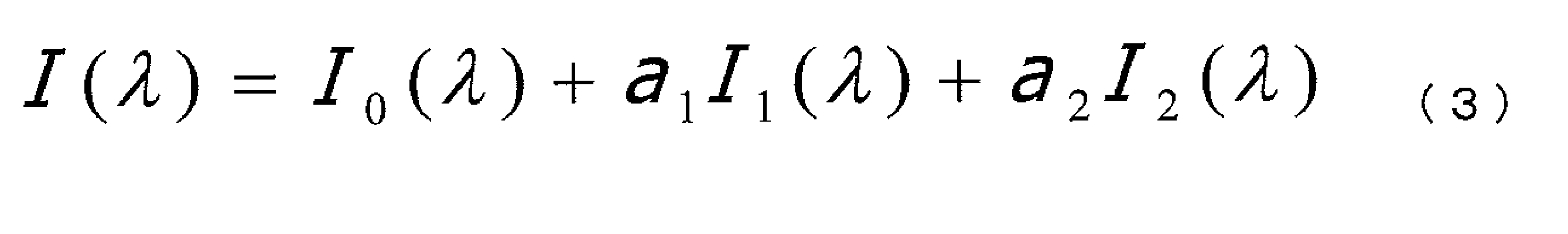
ai(i=1~2)は、各基底ベクトルの重み係数で、照明の色を表現する特性パラメータとなる。
得られた照明の色を表現する特性パラメータa1,a2を、式(3)に代入することによって、照明の分光分布I(λ)が得られる。
以上の手順にて得られた照明の分光分布を、入力画像を撮影した際の照明の分光分布I(λ)とする。
上記は、特定対象物として人間の顔に特化した場合の3D形状復元方法であるが、個体差があっても大体普遍的な形状を有する特定対象物であれば、非特許文献3をその特定対象物に拡張することで、入力画像からおおよその3次元形状を復元できる。
非特許文献5:R. Ramamoorthi and P. Hanrahan,"An efficient representation for irradiance environment maps" ,[online],Proc. ACM SIGGRAPH 01,pp. 497-500,2001,[平成21年1月26日検索]、インターネット<URL: http://www1.cs.columbia.edu/~ravir/papers/envmap/envmap.pdf>
非特許文献6:Ravi Ramamoorthi and Pat Hanrahan: "On the relationship between radiance and irradiance: determining the illumination from images of a convex Lambertian object" ,J. Opt. Soc. Am. A/Vol. 18, No. 10/October 2001.

一般に対象物の反射率は入射光と放射光の幾何条件に依存する。一般に、この反射特性は双方向反射率分布関数BRDF(Bidirectional Reflectance Distribution Function)として表現される。BRDFでは、表面反射成分(Secular component)とボディー反射成分(Body reflection component)の2つの成分から構成される場合が多い。
表面反射成分は、皮膚の表面で反射する成分である。
ボディー成分は、一旦、皮膚内部に入射し、その内部で拡散された光が、再度皮膚を通じて発散する光の成分である。
= 0のとき 上記以外 (21)
ここで、Iiは、入力画像の特定対象物領域におけるある画素の画素値を現しており、iはカラーチャネル(たとえば、R、G、Bなど)を表している。
BRi = Ii - Spi = Min(Ii, DRi) (22)
ここで、Min(x,y)は、xとyの最小値を出力する関数である。
ADi = BRi / Y (23)
いま、入力画像は、RGB表色系の画像であるものとして説明する。
特定対象物の領域におけるアルベドADiで表される各画素のRGB値から、式(1)に従って、三刺激値XYZを計算し、式(2)の左辺に代入する。
ここで、特定対象物の表面反射率についても、照明の分光分布と同様に可視光領域において無限次元の波形で表されるため、これを観測方程式(2)から解析的に計算することは出来ない。
そこで、特定対象物の表面反射率についても低次元の基底ベクトルの加重和で表す有限次元線形モデルを用いてモデル化する。

bi(i=1~3)は、各基底ベクトルの重み係数で、物体の色を表現する未知の特性パラメータとなる。
なお、特定対象物の表面反射率を多数集めて、それらを主成分分析して得られる基底ベクトルを用いても良い。

式(25)で得られた物体の色を表現する特性パラメータbi(i=1~3)を、式(24)に代入することで、対象物の領域における任意の画素における表面反射率が求められる。
ステップS7で算出した入力画像中の対象物における各画素の表面反射率を、その対象物領域の望ましい色が再現できるように設定された参照表面反射率を基に補正する。
この参照表面反射率は、人間の主観に依存するため一意に定義できるものではないが、主観評価実験を実施することであらかじめ求めておくことができる。例えば、画像処理ツールを用いて画像中の対象物領域の色を様々に変化させてその画質を評価する。そして、評価した中で最も好ましいと判断されたときの画像について、上述のステップS2およびステップS3を適用する。これにより、対象物領域における各画素の参照表面反射率を求めることができる。
さらに、入力画像中の対象物において形状的な特徴が利用できる場合には、その領域における色に対する表面反射率を、その対象物領域の参照表面反射率をRref(λ)としてもよい。例えば、対象物が顔の場合、頬、目尻、額などが特徴領域として与えられる。
以上の手法で、その対象物領域の参照表面反射率をあらかじめ得ておくことができる。
再現表面反射率Rmd(λ)の計算方法の一例を以下に示す。
Rmd(λ)=α・R(λ)+(1-α)・Rref(λ) (26)
ここで、αは、ゼロ以上1.0以下(0≦α≦1.0)の実数である。
まず、入力画像中の特定対象物における色の平均色、中央色(メジアン)、もしくは最頻色(モード)に相当する画素の色について、その表面反射率を求め、これをRavg(λ)とする。参照表面反射率については、上述のRref(λ)を用いる。
F(λ)= Rref(λ)/ Ravg(λ) (27)
そして、入力画像中の特定対象物における各画素の表面反射率R(λ)を、以下のように補正して、好ましい色を再現する再現表面反射率Rmd(λ)を算出する。
Rmd(λ)=α・F(λ)・R(λ)+(1-α)・R(λ) (28)
ここで、αは、ゼロ以上1.0以下(0≦α≦1.0)の実数である。
対象物領域内の色の分散が小さくなってしまうと、質感の低下を引き起こしてしまう場合があるからである。
特性パラメータbi(i=1~3)に対する補正式の一例を以下に示す。
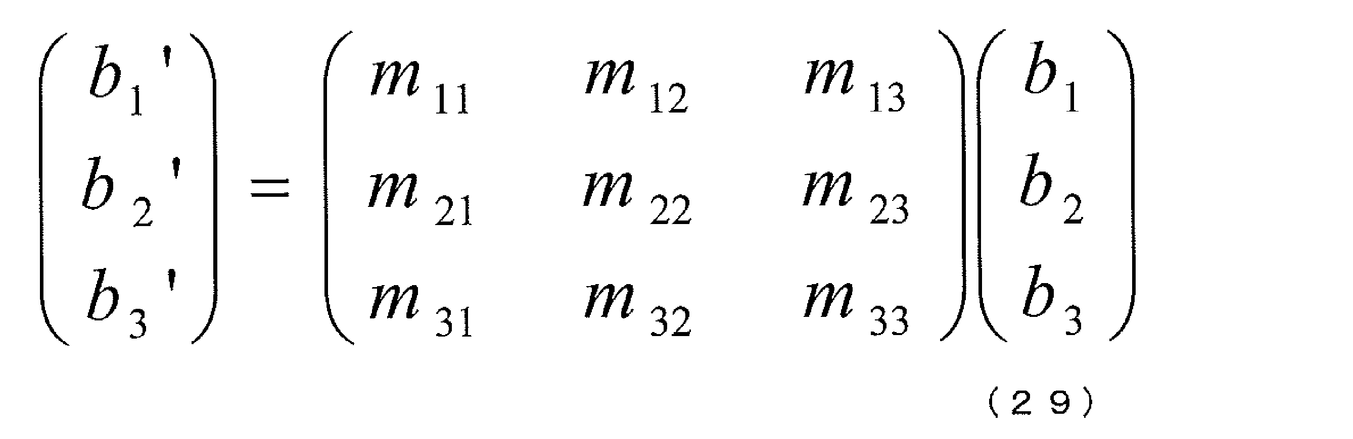
3×3行列が補正行列であり、その要素mij(i,j=1~3)は以下のようにして算出する。
それぞれに対して、入力画像中の対象物領域において同じ性質を有する色を求め、それらの色について表面反射率を求める。
入力画像中の対象物領域における平均色を、好ましいと判断されたときの画像中の対象物領域における中心色に補正する。Rref(1,λ)の特性パラメータであるbr1,i(i=1~3)を、式(29)の左辺の特性パラメータbi'(i=1~3)に、R(1,λ)の特性パラメータをb1,i(i=1~3)を、式(29)の右辺の特性パラメータbi(i=1~3)に代入する。
すると、式(29)は、未知である要素mij(i,j=1~3)に関する連立方程式となる。
対象物における3個以上の色について同様にすれば、方程式と未知数との数の関係から、未知である要素mij(i,j=1~3)を解くことができ、式(29)の補正行列が得られる。
図8からもわかるように、入力画像中の特定対象物の領域における特性パラメータの分布が、望ましい色再現をもたらす参照表面反射率における特性パラメータの分布に維持されることで色の分散の変化(偏りや低下)を抑えることができ、補正後の色の質感が損なわれることがない。
入力画像中の対象物における各画素の表面反射率を構成する特性パラメータbi(i=1~3)に、式(29)の補正行列を適用して、補正後の特性パラメータを算出し、式(24)に代入することで、入力画像中の対象物における各画素の補正後の再現表面反射率を得ることが出来る。
補正後のアルベドADi'に拡散反射成分の輝度を乗算し、ボディー反射成分BRi'を計算する。
BRi'= ADi'× Y (31)
ここで、Yは拡散反射成分DRiの輝度、すなわち、式(1)で求められる三刺激値のY成分である。そして、ボディー反射成分BRiに表面反射成分SPiを加算することで、色補正後の画素値Ii'が得られる。
Ii'= Bri'+ Spi (32)
上記した方法にしたがって、入力画像中の対象物領域の色を補正した画像を出力画像として出力する。
カラー画像処理装置101は、入力画像1に対して色補正を施し出力画像2を出力する装置である。カラー画像処理装置101は、対象物領域検出部3と、分光分布復元部(照明の分光分布復元部)4と、代表表面反射率保存メモリ(対象物領域の代表表面反射率保存メモリ)5と、3次元情報復元部(対象物領域の3次元情報復元部)6と、反射情報復元部(対象物領域の表面反射成分とボディー反射成分復元部)7と、アルベド計算部(対象物領域のアルベド計算部)8と、表面反射率復元部(対象物領域の表面反射率復元部)9と、補正アルベド算出部(表面反射率補正によるアルベド補正部)10と、参照表面反射率保存メモリ(対象物領域の参照表面反射率保存メモリ)11と、再現色算出部(対象物領域の再現色算出部)12と、を備える。
ここで、入力画像1から検出する対象物は、上記のように、人の顔などのようにその対象物領域の色と形状特徴がある程度限定できるものである。検出方法については、上記した手法に従えばよい。なお、入力画像1から目的とする対象物が検出されない場合には、入力画像1を出力画像2として出力する。
3次元形状は、3次元情報復元部6によって算出される。対象物領域の3次元形状は、図3のステップS4に記載したように、法線ベクトルである。反射情報復元部7では、放射照度の計算として、上述のステップS4で述べた処理が実行される。
また、反射情報復元部7は、上述のステップS5で述べた処理方法に従って、対象物領域における表面反射成分及びボディー反射成分を復元(算出)する。
画像情報取得部110は、対象物領域検出部3と、3次元情報復元部6とによって構成される。
反射情報復元部120は、反射情報復元部7に対応する。
アルベド計算部130は、アルベド計算部8に対応する。
アルベド補正処理部140において、分光分布復元部141は、分光分布復元部4と対象物領域の代表表面反射率保存メモリ5とによって構成される。また、アルベド補正部142は、表面反射率復元部9、補正アルベド算出部10、及び参照表面反射率保存メモリ11によって構成される。
再現色算出部150は、再現色算出部12に対応する。
なお、図2または図9に示したカラー画像処理装置の構成は一例であり、同様の機能を実現する装置であればその他の構成をとってもよい。
カラー画像処理装置を構成する各構成要素がコンピュータで実現可能であること、およびプログラムとして実現可能であることは、実施形態1に限らず、その他の実施形態でも同様である。
次に、実施形態2のカラー画像処理方法について説明する。図10は、本発明による実施形態2のカラー画像処理方法を示すフローチャートである。実施形態2のカラー画像処理方法は、実施形態1のカラー画像処理方法のステップS7、ステップS8(図3)で行われる2つの処理を一つにまとめた処理を実施する。具体的には、入力画像中の対象物における各画素の表面反射率を復元する処理(ステップS7)と、復元された表面反射率を補正して、補正後のアルベドを計算する処理(ステップS8)とを、線形計算に基づく補正式に置き換える。これによって、実施形態1のカラー画像処理方法と同等の補正結果をもたらすカラー画像処理方法である。
図10におけるステップS1からステップS6とステップS9の処理は、実施形態1における処理と同様であるため説明を省略し、ステップS10について、図2に示す構成例を用いて説明する。
その結果、補正後の対象物領域の表面反射率R'(λ)の特性パラメータbi'(i=1~3)は式(29)で算出される。次に、補正後の表面反射率R'(λ)は、特性パラメータbi'(i=1~3)を式(24)に代入することで計算される。補正後の表面反射率R'(λ)は、式(33)のようになる。


このように、一つの線形計算に基づく補正式に置き換えることによって、処理時間の高速化を図ることができる。
具体的には、アルベド補正部13は、補正式の作成において、照明の分光分布とアルベドとを用いて、対象物領域の表面反射率を復元し、表面反射率を用いて、アルベドを補正する補正式を作成する。また、アルベド補正部13は、参照表面反射率を用いて表面反射率を補正して再現表面反射率を算出し、再現表面反射率を用いて補正式を作成する。参照表面反射率は、参照表面反射率保存メモリ11に記憶されている。
上記各実施形態のカラー画像処理方法及び装置は、コンピュータを用いて実現することができる。カラー画像処理方法及び装置の各処理は、ソフトウェア、ハードウェア、ファームフェアのいずれか二つ以上の組み合わせで実現することもできる。
例えば、図2に示すカラー画像処理装置100を、プログラムを用いて実現する場合、プログラム(プログラムの命令群)は、少なくとも次の手順をコンピュータに実行させる。プログラムは、コンピュータのメモリにロードされ、CPUの制御のもとで各命令が実行される。
(f)色情報を用いて照明の分光分布を復元する分光分布復元手順。(g)照明の分光分布と前記アルベドとを用いて、対象物領域の表面反射率を復元し、復元した表面反射率に基づいてアルベドを補正して補正アルベドを算出するアルベド補正手順。
さらに、参照表面反射率保存メモリは、3以上の参照表面反射率を保存することが好ましい。この場合、アルベド補正手順は、3以上の参照表面反射率を用いて、前記表面反射率を補正する。
なお、上述した各手順は、プログラムで実現する手順の一例を示したものであり、これらに限られることはない。また、複数の手順のうちの一部をハードウェアやファームウェアによって実現することも可能である。
プログラムは、記録媒体に記録して提供することも可能であり、また、インターネットその他の通信媒体を介して伝送することにより提供することも可能である。また、記憶媒体には、例えば、フレキシブルディスク、ハードディスク、磁気ディスク、光磁気ディスク、CD-ROM、DVD、ROMカートリッジ、バッテリバックアップ付きRAMメモリカートリッジ、フラッシュメモリカートリッジ、不揮発性RAMカートリッジ等が含まれる。また、通信媒体には、電話回線等の有線通信媒体、マイクロ波回線等の無線通信媒体等が含まれる。
2 出力画像
3 対象物領域検出部
4 分光分布復元部
5 対象物領域の代表表面反射率保存メモリ
6 3次元情報復元部
7 反射情報復元部
8 アルベド計算部
9 表面反射率復元部
10 補正アルベド算出部
11 参照表面反射率保存メモリ
12 再現色算出部
13、142 アルベド補正部
100、101、102 カラー画像処理装置
110 画像情報取得部
120 反射情報復元部
130 アルベド計算部
140 アルベド補正処理部
141 分光分布復元部
150 再現色算出部
Claims (19)
- 入力画像に基づいて対象物領域を検出し、
前記対象物領域の色情報と3次元情報とを取得し、
前記色情報と前記3次元情報とに基づいて、前記対象物領域の表面反射成分及びボディー反射成分を復元し、
前記色情報から表面反射成分とボディー反射成分とを除去してアルベドを算出し、
前記色情報と前記アルベドを用いて表面反射率を復元し、
前記表面反射率を用いて前記アルベドを補正した補正アルベドを算出し、
前記補正アルベドへ前記ボディー反射成分と前記表面反射成分とを付加して前記対象物領域の再現色を算出し、出力画像を生成するカラー画像処理方法。 - 前記表面反射率の復元は、前記色情報を用いて照明の分光分布を復元し、前記照明の分光分布と前記アルベドとを用いて、前記対象物領域の表面反射率を復元することを特徴とする請求項1記載のカラー画像処理方法。
- 前記補正アルベドの算出は、予め前記対象物領域に応じて設定され、参照表面反射率保存メモリに保存した参照表面反射率を用いて前記表面反射率を補正して再現表面反射率を算出し、前記再現表面反射率を用いてアルベドを補正することを特徴とする請求項2記載のカラー画像処理方法。
- 前記参照表面反射率保存メモリは、3以上の参照表面反射率を保存し、
前記補正アルベドの算出は、前記3以上の参照表面反射率を用いて、前記表面反射率を補正することを特徴とする請求項3記載のカラー画像処理方法。 - 前記照明の分光分布の復元は、前記色情報に加え、予め前記対象物領域に応じて設定された代表表面反射率を用いて復元することを特徴とする請求項2乃至4のいずれか一項に記載のカラー画像処理方法。
- 前記補正アルベドの算出は、前記アルベドを補正する補正式を作成し、前記補正式を用いた行列変換によって補正アルベドを算出することを特徴とする請求項1乃至5のいずれか一項に記載のカラー画像処理方法。
- 入力画像に基づいて対象物領域を検出し、前記対象物領域の色情報と3次元情報とを取得する画像情報取得手段と、
前記色情報と前記3次元情報とに基づいて、前記対象物領域の表面反射成分及びボディー反射成分を復元する反射情報復元手段と、
前記色情報から表面反射成分とボディー反射成分とを除去したアルベドを算出するアルベド計算手段と、
前記色情報と前記アルベドを用いて表面反射率を復元し、前記表面反射率を用いて前記アルベドを補正した補正アルベドを算出するアルベド補正処理手段と、
前記補正アルベドへ前記ボディー反射成分と前記表面反射成分とを付加して前記対象物領域の再現色を算出し、出力画像を生成する再現色算出手段と、を備えるカラー画像処理装置。 - 前記アルベド補正処理手段は、
前記色情報を用いて照明の分光分布を復元する分光分布復元手段と、
前記照明の分光分布と前記アルベドとを用いて、前記対象物領域の表面反射率を復元する表面反射率復元手段と、
前記表面反射率を用いて前記アルベドを補正して補正アルベドを算出する補正アルベド算出手段と、を有することを特徴とする請求項7記載のカラー画像処理装置。 - 前記アルベド補正処理手段は、
予め前記対象物領域に応じて設定された参照表面反射率を保存する参照表面反射率保存メモリを、さらに備え、
前記補正アルベド算出手段は、前記参照表面反射率を用いて前記表面反射率を補正して再現表面反射率を算出し、前記再現表面反射率を用いてアルベドを補正することを特徴とする請求項8記載のカラー画像処理装置。 - 前記参照表面反射率保存メモリは、3以上の参照表面反射率を保存し、
前記補正アルベド算出手段は、前記3以上の参照表面反射率を用いて、前記表面反射率を補正することを特徴とする請求項9記載のカラー画像処理装置。 - 前記アルベド補正処理手段は、
前記色情報を用いて照明の分光分布を復元する分光分布復元手段と、
前記照明の分光分布と前記アルベドとを用いて、対象物領域の表面反射率を復元し、前記表面反射率を用いて、前記アルベドを補正する補正式を作成し、前記補正式を用いた行列変換によって補正アルベドを算出するアルベド補正手段と、を有することを特徴とする請求項7記載のカラー画像処理装置。 - 前記アルベド補正処理手段は、
前記対象物領域の参照表面反射率を保存する参照表面反射率保存メモリを、さらに備え、
前記アルベド補正手段は、前記参照表面反射率を用いて前記表面反射率を補正して再現表面反射率を算出し、再現表面反射率を用いて前記補正式を作成することを特徴とする請求項11記載のカラー画像処理装置。 - 前記分光分布復元手段は、
前記対象物領域の代表表面反射率を保存する代表表面反射率保存メモリを備え、
前記色情報に加え、前記対象物領域の代表表面反射率を用いて前記照明の分光分布を復元することを特徴とする請求項8乃至12のいずれか一項に記載のカラー画像処理装置。 - コンピュータに、
入力画像に基づいて対象物領域を検出し、前記対象物領域の色情報と3次元情報とを取得する画像情報取得手順と、
前記色情報と前記3次元情報とに基づいて、前記対象物領域の表面反射成分及びボディー反射成分を復元する反射情報復元手順と、
前記色情報から表面反射成分とボディー反射成分とを除去してアルベドを算出するアルベド計算手順と、
前記色情報と前記アルベドを用いて表面反射率を復元し、前記表面反射率を用いて前記アルベドを補正した補正アルベドを算出するアルベド補正処理手順と、
前記補正アルベドへ前記ボディー反射成分と前記表面反射成分とを付加して前記対象物領域の再現色を算出し、出力画像を生成する再現色算出手順と、を実行させるカラー画像処理プログラムを記録したコンピュータ読み取り可能な記録媒体。 - アルベド補正処理手順は、
前記色情報を用いて照明の分光分布を復元する分光分布復元手順と、
前記照明の分光分布と前記アルベドとを用いて、前記対象物領域の表面反射率を復元し、前記表面反射率を用いてアルベドを補正して補正アルベドを算出するアルベド補正手順と、を備えることを特徴とする請求項14記載のカラー画像処理プログラムを記録したコンピュータ読み取り可能な記録媒体。 - 前記アルベド補正手順は、予め前記対象物領域に応じて設定され、参照表面反射率保存メモリに保存した参照表面反射率を用いて前記表面反射率を補正して再現表面反射率を算出し、前記再現表面反射率を用いて前記アルベドを補正することを特徴とする請求項15記載のカラー画像処理プログラムを記録したコンピュータ読み取り可能な記録媒体。
- 前記参照表面反射率保存メモリは、3以上の参照表面反射率を保存し、
前記アルベド補正手順は、前記3以上の参照表面反射率を用いて、前記表面反射率を補正することを特徴とする請求項16記載のカラー画像処理プログラムを記録したコンピュータ読み取り可能な記録媒体。 - 前記分光分布復元手順は、前記色情報に加え、予め前記対象物領域に応じて設定された代表表面反射率を用いて復元することを特徴とする請求項15乃至17のいずれか一項に記載のカラー画像処理プログラムを記録したコンピュータ読み取り可能な記録媒体。
- 前記アルベド補正手順は、前記アルベドを補正する補正式を作成し、前記補正式を用いた行列変換によって補正アルベドを算出することを特徴とする請求項14乃至18のいずれか一項に記載のカラー画像処理プログラムを記録したコンピュータ読み取り可能な記録媒体。
Priority Applications (4)
| Application Number | Priority Date | Filing Date | Title |
|---|---|---|---|
| US13/143,394 US8705855B2 (en) | 2009-01-27 | 2010-01-27 | Color image processing method, color image processing device, and color image processing program |
| CN2010800056100A CN102301391B (zh) | 2009-01-27 | 2010-01-27 | 彩色图像处理方法、彩色图像处理设备以及彩色图像处理程序 |
| EP10735634.7A EP2393061B1 (en) | 2009-01-27 | 2010-01-27 | Color image processing method, color image processing device and recording medium |
| JP2010548417A JP5648483B2 (ja) | 2009-01-27 | 2010-01-27 | カラー画像処理方法、カラー画像処理装置およびカラー画像処理プログラム |
Applications Claiming Priority (2)
| Application Number | Priority Date | Filing Date | Title |
|---|---|---|---|
| JP2009015120 | 2009-01-27 | ||
| JP2009-015120 | 2009-01-27 |
Publications (1)
| Publication Number | Publication Date |
|---|---|
| WO2010087162A1 true WO2010087162A1 (ja) | 2010-08-05 |
Family
ID=42395426
Family Applications (1)
| Application Number | Title | Priority Date | Filing Date |
|---|---|---|---|
| PCT/JP2010/000458 WO2010087162A1 (ja) | 2009-01-27 | 2010-01-27 | カラー画像処理方法、カラー画像処理装置および記録媒体 |
Country Status (5)
| Country | Link |
|---|---|
| US (1) | US8705855B2 (ja) |
| EP (1) | EP2393061B1 (ja) |
| JP (1) | JP5648483B2 (ja) |
| CN (1) | CN102301391B (ja) |
| WO (1) | WO2010087162A1 (ja) |
Cited By (6)
| Publication number | Priority date | Publication date | Assignee | Title |
|---|---|---|---|---|
| CN107533757A (zh) * | 2015-05-22 | 2018-01-02 | 索尼公司 | 处理图像的装置和方法 |
| JP2018151832A (ja) * | 2017-03-13 | 2018-09-27 | キヤノン株式会社 | 情報処理装置、情報処理方法、および、プログラム |
| US10297055B2 (en) | 2013-05-14 | 2019-05-21 | Sony Corporation | Image processing apparatus and method for modifying a display texture of an image |
| US10373344B2 (en) | 2014-04-23 | 2019-08-06 | Sony Corporation | Image processing apparatus and method for adjusting intensity of a reflective property of an object in a displayed image |
| US10636125B2 (en) | 2015-05-08 | 2020-04-28 | Sony Corporation | Image processing apparatus and method |
| JP2022036319A (ja) * | 2020-09-27 | 2022-03-07 | ベイジン バイドゥ ネットコム サイエンス テクノロジー カンパニー リミテッド | 画像のレンダリング方法、装置、電子デバイス、コンピュータ可読記憶媒体及びコンピュータプログラム |
Families Citing this family (19)
| Publication number | Priority date | Publication date | Assignee | Title |
|---|---|---|---|---|
| JP5648483B2 (ja) * | 2009-01-27 | 2015-01-07 | 日本電気株式会社 | カラー画像処理方法、カラー画像処理装置およびカラー画像処理プログラム |
| JP5533670B2 (ja) * | 2009-01-29 | 2014-06-25 | 日本電気株式会社 | カラー画像処理方法、カラー画像処理装置およびカラー画像処理プログラム |
| EP2590135A1 (en) * | 2010-06-30 | 2013-05-08 | Nec Corporation | Color image processing method, color image processing device, and color image processing program |
| US8582873B2 (en) * | 2011-06-16 | 2013-11-12 | Tandent Vision Science, Inc. | Use of an object database in an image process |
| US9230344B2 (en) * | 2012-01-12 | 2016-01-05 | Christopher Joseph Vranos | Software, system, and method of changing colors in a video |
| CN105917383B (zh) * | 2014-01-21 | 2017-10-27 | 三菱电机株式会社 | 动态图像再现装置 |
| JP6350069B2 (ja) * | 2014-07-22 | 2018-07-04 | 富士ゼロックス株式会社 | 情報処理システム、情報処理装置およびプログラム |
| CN106327505B (zh) | 2015-06-26 | 2020-05-05 | 微软技术许可有限责任公司 | 机器视觉处理系统、设备、方法及计算机可读存储介质 |
| JP6624827B2 (ja) * | 2015-07-13 | 2019-12-25 | キヤノン株式会社 | 情報処理装置、情報処理方法、コンピュータプログラム |
| JP6584179B2 (ja) | 2015-07-13 | 2019-10-02 | キヤノン株式会社 | 情報処理装置、情報処理方法、コンピュータプログラム |
| CN105574821A (zh) * | 2015-12-10 | 2016-05-11 | 浙江传媒学院 | 基于数据的软性阴影去除方法 |
| KR102373926B1 (ko) * | 2016-02-05 | 2022-03-14 | 삼성전자주식회사 | 이동체 및 이동체의 위치 인식 방법 |
| US11452442B2 (en) * | 2016-06-15 | 2022-09-27 | Oregon Health & Science University | Systems and methods for automated widefield optical coherence tomography angiography |
| KR20180047367A (ko) | 2016-10-31 | 2018-05-10 | 삼성전자주식회사 | 영상 처리 장치 및 방법 |
| WO2018105062A1 (ja) * | 2016-12-07 | 2018-06-14 | オリンパス株式会社 | 画像処理装置及び画像処理方法 |
| US11333603B2 (en) * | 2018-10-30 | 2022-05-17 | Canon Kabushiki Kaisha | Processing apparatus, processing method, and storage medium |
| JP7334458B2 (ja) * | 2019-04-24 | 2023-08-29 | 富士フイルムビジネスイノベーション株式会社 | 画像処理装置及び画像処理プログラム |
| CN111260577B (zh) * | 2020-01-15 | 2023-04-18 | 哈尔滨工业大学 | 基于多引导图和自适应特征融合的人脸图像复原系统 |
| CN111612882B (zh) * | 2020-06-10 | 2023-04-07 | 腾讯科技(深圳)有限公司 | 图像处理方法、装置、计算机存储介质及电子设备 |
Citations (8)
| Publication number | Priority date | Publication date | Assignee | Title |
|---|---|---|---|---|
| JPH10229499A (ja) | 1997-02-14 | 1998-08-25 | Nec Corp | 色変換方法及びその装置並びにプログラムを記録した機械読み取り可能な記録媒体 |
| JP2001092956A (ja) | 1999-09-22 | 2001-04-06 | Nec Corp | 自動色補正装置及び自動色補正方法並びにその制御プログラムを記録した記録媒体 |
| JP2003317084A (ja) | 2002-04-19 | 2003-11-07 | Nec Corp | 顔画像からの目検出システム、目検出方法および目検出用プログラム |
| JP2004045189A (ja) | 2002-07-11 | 2004-02-12 | Matsushita Electric Ind Co Ltd | 色補正装置及び色補正方法 |
| JP2006277748A (ja) | 2005-03-29 | 2006-10-12 | Mitsubishi Electric Research Laboratories Inc | コンピュータにより実施される、顔の皮膚反射モデルを生成する方法 |
| JP2008225971A (ja) * | 2007-03-14 | 2008-09-25 | Matsushita Electric Ind Co Ltd | 画像合成装置およびそれを用いた画像照合装置ならびに画像合成方法 |
| JP2008225970A (ja) * | 2007-03-14 | 2008-09-25 | Matsushita Electric Ind Co Ltd | 画像合成装置およびそれを用いた画像照合装置ならびに画像合成方法 |
| JP2009015120A (ja) | 2007-07-06 | 2009-01-22 | Yamaha Corp | 電子楽器の鍵盤装置 |
Family Cites Families (11)
| Publication number | Priority date | Publication date | Assignee | Title |
|---|---|---|---|---|
| JP2000090233A (ja) * | 1998-09-08 | 2000-03-31 | Olympus Optical Co Ltd | 画像処理装置 |
| CA2385173A1 (en) * | 1999-09-17 | 2001-03-29 | Nature Technology Co., Ltd. | Image capturing system, image processing system, and camera |
| EP1906674A4 (en) | 2005-07-13 | 2011-06-22 | Nec Corp | METHOD AND DEVICE FOR COLOR CORRECTION |
| JP2007264439A (ja) * | 2006-03-29 | 2007-10-11 | Kyocera Mita Corp | 画像形成装置、画像形成装置のトナー濃度調整方法、プログラム、及び記録媒体 |
| CN101356546B (zh) * | 2006-05-29 | 2011-10-12 | 松下电器产业株式会社 | 图像高分辨率化装置、方法及系统 |
| KR101342987B1 (ko) * | 2006-11-21 | 2013-12-18 | 톰슨 라이센싱 | 3d 이미지의 컬러 보정을 위한 방법 및 시스템 |
| CN101146233A (zh) * | 2007-09-26 | 2008-03-19 | 东南大学 | 一种光源颜色计算和图像校正方法 |
| US9485391B2 (en) * | 2008-02-22 | 2016-11-01 | Nec Corporation | Method, apparatus and program for restoring and correcting surface reflectance with color image processing |
| JP4469021B2 (ja) * | 2008-07-08 | 2010-05-26 | パナソニック株式会社 | 画像処理方法、画像処理装置、画像処理プログラム、画像合成方法、および画像合成装置 |
| US8457389B2 (en) * | 2008-09-03 | 2013-06-04 | Nec Corporation | Image processing device, image processing method and image processing program |
| JP5648483B2 (ja) * | 2009-01-27 | 2015-01-07 | 日本電気株式会社 | カラー画像処理方法、カラー画像処理装置およびカラー画像処理プログラム |
-
2010
- 2010-01-27 JP JP2010548417A patent/JP5648483B2/ja active Active
- 2010-01-27 EP EP10735634.7A patent/EP2393061B1/en active Active
- 2010-01-27 WO PCT/JP2010/000458 patent/WO2010087162A1/ja active Application Filing
- 2010-01-27 CN CN2010800056100A patent/CN102301391B/zh active Active
- 2010-01-27 US US13/143,394 patent/US8705855B2/en active Active
Patent Citations (9)
| Publication number | Priority date | Publication date | Assignee | Title |
|---|---|---|---|---|
| JPH10229499A (ja) | 1997-02-14 | 1998-08-25 | Nec Corp | 色変換方法及びその装置並びにプログラムを記録した機械読み取り可能な記録媒体 |
| JP2001092956A (ja) | 1999-09-22 | 2001-04-06 | Nec Corp | 自動色補正装置及び自動色補正方法並びにその制御プログラムを記録した記録媒体 |
| JP3264273B2 (ja) | 1999-09-22 | 2002-03-11 | 日本電気株式会社 | 自動色補正装置及び自動色補正方法並びにその制御プログラムを記録した記録媒体 |
| JP2003317084A (ja) | 2002-04-19 | 2003-11-07 | Nec Corp | 顔画像からの目検出システム、目検出方法および目検出用プログラム |
| JP2004045189A (ja) | 2002-07-11 | 2004-02-12 | Matsushita Electric Ind Co Ltd | 色補正装置及び色補正方法 |
| JP2006277748A (ja) | 2005-03-29 | 2006-10-12 | Mitsubishi Electric Research Laboratories Inc | コンピュータにより実施される、顔の皮膚反射モデルを生成する方法 |
| JP2008225971A (ja) * | 2007-03-14 | 2008-09-25 | Matsushita Electric Ind Co Ltd | 画像合成装置およびそれを用いた画像照合装置ならびに画像合成方法 |
| JP2008225970A (ja) * | 2007-03-14 | 2008-09-25 | Matsushita Electric Ind Co Ltd | 画像合成装置およびそれを用いた画像照合装置ならびに画像合成方法 |
| JP2009015120A (ja) | 2007-07-06 | 2009-01-22 | Yamaha Corp | 電子楽器の鍵盤装置 |
Non-Patent Citations (9)
| Title |
|---|
| JOJI TAJIMA: "Image engineering series 10, Color image reproduction theory, Fundamentals of color management", MARUZEN CO., LTD., 30 September 1996 (1996-09-30), pages 33 - 39 |
| KENJI INOSE ET AL.: "Fukusu Keisoku ni yoru Zenshu 3-jigen Model Seisei no Tameno Fukusu Texture no Seamless na Gosei Shuho", TRANSACTIONS OF INFORMATION PROCESSING SOCIETY OF JAPAN COMPUTER VISION TO IMAGE MEDIA, vol. 1, no. 2, 15 November 2008 (2008-11-15), pages 136 - 151, XP008166973 * |
| R. BASRI, D. JACOBS: "Lambertian Reflectance and Linear Subspaces", PROC. IEEE INTL CONF. COMPUTER VISION 01, 2001, pages 383 - 389 |
| R. RAMAMOORTHI, P. HANRAHAN: "An efficient representation for irradiance environment maps", ONLINE], PROC. ACM SIGGRAPH 01, 2001, pages 497 - 500 |
| RAVI RAMAMOORTHI, PAT HANRAHAN: "On the relationship between radiance and irradiance: determining the illumination from images of a convex Lambertian object", J. OPT. SOC. AM. A, vol. 18, no. 10, October 2001 (2001-10-01) |
| RUI ISHIYAMA: "Recognition of Non-Frontal Facial Images by Pose Conversion using Generic 3D Face Model", IEICE, GENERAL CONFERENCE 2007, vol. D-12-085, 2007, pages 201 |
| See also references of EP2393061A4 * |
| TOSHINORI HOSOI, TETSUAKI SUZUKI, ATUSHI SATOH: "Face detection based on Generalized LVQ", FIT2002, September 2002 (2002-09-01), pages 1 - 30 |
| YOSHIO IWAI ET AL.: "Gazo Shori ni yoru Kao Kenshutsu to Kao Ninshiki", INFORMATION PROCESSING SOCIETY OF JAPAN KENKYU HOKOKU, vol. 2005, no. 38, 13 May 2005 (2005-05-13), pages 343 - 368, XP008166962 * |
Cited By (11)
| Publication number | Priority date | Publication date | Assignee | Title |
|---|---|---|---|---|
| US10297055B2 (en) | 2013-05-14 | 2019-05-21 | Sony Corporation | Image processing apparatus and method for modifying a display texture of an image |
| US10373344B2 (en) | 2014-04-23 | 2019-08-06 | Sony Corporation | Image processing apparatus and method for adjusting intensity of a reflective property of an object in a displayed image |
| US10636125B2 (en) | 2015-05-08 | 2020-04-28 | Sony Corporation | Image processing apparatus and method |
| CN107533757A (zh) * | 2015-05-22 | 2018-01-02 | 索尼公司 | 处理图像的装置和方法 |
| US10445621B2 (en) | 2015-05-22 | 2019-10-15 | Sony Corporation | Image processing apparatus and image processing method |
| CN107533757B (zh) * | 2015-05-22 | 2022-06-07 | 索尼公司 | 处理图像的装置和方法 |
| JP2018151832A (ja) * | 2017-03-13 | 2018-09-27 | キヤノン株式会社 | 情報処理装置、情報処理方法、および、プログラム |
| US11039076B2 (en) | 2017-03-13 | 2021-06-15 | Canon Kabushiki Kaisha | Information processing apparatus, information processing method, and storage medium |
| JP2022036319A (ja) * | 2020-09-27 | 2022-03-07 | ベイジン バイドゥ ネットコム サイエンス テクノロジー カンパニー リミテッド | 画像のレンダリング方法、装置、電子デバイス、コンピュータ可読記憶媒体及びコンピュータプログラム |
| US11636646B2 (en) | 2020-09-27 | 2023-04-25 | Beijing Baidu Netcom Science And Technology Co., Ltd. | Method and apparatus for rendering image |
| JP7293277B2 (ja) | 2020-09-27 | 2023-06-19 | ベイジン バイドゥ ネットコム サイエンス テクノロジー カンパニー リミテッド | 画像のレンダリング方法、装置、電子デバイス、コンピュータ可読記憶媒体及びコンピュータプログラム |
Also Published As
| Publication number | Publication date |
|---|---|
| JP5648483B2 (ja) | 2015-01-07 |
| CN102301391B (zh) | 2013-07-17 |
| EP2393061A4 (en) | 2013-08-21 |
| US8705855B2 (en) | 2014-04-22 |
| EP2393061B1 (en) | 2016-09-07 |
| EP2393061A1 (en) | 2011-12-07 |
| CN102301391A (zh) | 2011-12-28 |
| JPWO2010087162A1 (ja) | 2012-08-02 |
| US20110274351A1 (en) | 2011-11-10 |
Similar Documents
| Publication | Publication Date | Title |
|---|---|---|
| JP5648483B2 (ja) | カラー画像処理方法、カラー画像処理装置およびカラー画像処理プログラム | |
| JP5533670B2 (ja) | カラー画像処理方法、カラー画像処理装置およびカラー画像処理プログラム | |
| JP6004481B2 (ja) | カラー画像処理方法、カラー画像処理装置およびカラー画像処理プログラム | |
| JP5158100B2 (ja) | カラー画像処理方法、装置およびプログラム | |
| US8855371B2 (en) | Color image processing method, color image processing device, and color image processing program | |
| JP4288530B2 (ja) | 色補正方法および色補正装置 | |
| US9398282B2 (en) | Image processing apparatus, control method, and computer-readable medium | |
| Jang et al. | Spectrum‐Based Color Reproduction Algorithm for Makeup Simulation of 3D Facial Avatar | |
| JP5824423B2 (ja) | 照明光色推定装置、照明光色推定方法及び照明光色推定プログラム | |
| JP4626776B2 (ja) | 色補正方法および色補正装置 | |
| JP2012028973A (ja) | 照明光推定装置、照明光推定方法および照明光推定プログラム | |
| JP2004045189A (ja) | 色補正装置及び色補正方法 |
Legal Events
| Date | Code | Title | Description |
|---|---|---|---|
| WWE | Wipo information: entry into national phase |
Ref document number: 201080005610.0 Country of ref document: CN |
|
| 121 | Ep: the epo has been informed by wipo that ep was designated in this application |
Ref document number: 10735634 Country of ref document: EP Kind code of ref document: A1 |
|
| REEP | Request for entry into the european phase |
Ref document number: 2010735634 Country of ref document: EP |
|
| WWE | Wipo information: entry into national phase |
Ref document number: 2010548417 Country of ref document: JP Ref document number: 2010735634 Country of ref document: EP |
|
| WWE | Wipo information: entry into national phase |
Ref document number: 13143394 Country of ref document: US |
|
| NENP | Non-entry into the national phase |
Ref country code: DE |