WO2010082467A1 - プラズマcvd装置 - Google Patents
プラズマcvd装置 Download PDFInfo
- Publication number
- WO2010082467A1 WO2010082467A1 PCT/JP2010/000106 JP2010000106W WO2010082467A1 WO 2010082467 A1 WO2010082467 A1 WO 2010082467A1 JP 2010000106 W JP2010000106 W JP 2010000106W WO 2010082467 A1 WO2010082467 A1 WO 2010082467A1
- Authority
- WO
- WIPO (PCT)
- Prior art keywords
- chamber
- plasma cvd
- cvd apparatus
- shower plate
- substrate
- Prior art date
- Legal status (The legal status is an assumption and is not a legal conclusion. Google has not performed a legal analysis and makes no representation as to the accuracy of the status listed.)
- Ceased
Links
Images

Classifications
-
- C—CHEMISTRY; METALLURGY
- C23—COATING METALLIC MATERIAL; COATING MATERIAL WITH METALLIC MATERIAL; CHEMICAL SURFACE TREATMENT; DIFFUSION TREATMENT OF METALLIC MATERIAL; COATING BY VACUUM EVAPORATION, BY SPUTTERING, BY ION IMPLANTATION OR BY CHEMICAL VAPOUR DEPOSITION, IN GENERAL; INHIBITING CORROSION OF METALLIC MATERIAL OR INCRUSTATION IN GENERAL
- C23C—COATING METALLIC MATERIAL; COATING MATERIAL WITH METALLIC MATERIAL; SURFACE TREATMENT OF METALLIC MATERIAL BY DIFFUSION INTO THE SURFACE, BY CHEMICAL CONVERSION OR SUBSTITUTION; COATING BY VACUUM EVAPORATION, BY SPUTTERING, BY ION IMPLANTATION OR BY CHEMICAL VAPOUR DEPOSITION, IN GENERAL
- C23C16/00—Chemical coating by decomposition of gaseous compounds, without leaving reaction products of surface material in the coating, i.e. chemical vapour deposition [CVD] processes
- C23C16/44—Chemical coating by decomposition of gaseous compounds, without leaving reaction products of surface material in the coating, i.e. chemical vapour deposition [CVD] processes characterised by the method of coating
-
- C—CHEMISTRY; METALLURGY
- C23—COATING METALLIC MATERIAL; COATING MATERIAL WITH METALLIC MATERIAL; CHEMICAL SURFACE TREATMENT; DIFFUSION TREATMENT OF METALLIC MATERIAL; COATING BY VACUUM EVAPORATION, BY SPUTTERING, BY ION IMPLANTATION OR BY CHEMICAL VAPOUR DEPOSITION, IN GENERAL; INHIBITING CORROSION OF METALLIC MATERIAL OR INCRUSTATION IN GENERAL
- C23C—COATING METALLIC MATERIAL; COATING MATERIAL WITH METALLIC MATERIAL; SURFACE TREATMENT OF METALLIC MATERIAL BY DIFFUSION INTO THE SURFACE, BY CHEMICAL CONVERSION OR SUBSTITUTION; COATING BY VACUUM EVAPORATION, BY SPUTTERING, BY ION IMPLANTATION OR BY CHEMICAL VAPOUR DEPOSITION, IN GENERAL
- C23C16/00—Chemical coating by decomposition of gaseous compounds, without leaving reaction products of surface material in the coating, i.e. chemical vapour deposition [CVD] processes
- C23C16/44—Chemical coating by decomposition of gaseous compounds, without leaving reaction products of surface material in the coating, i.e. chemical vapour deposition [CVD] processes characterised by the method of coating
- C23C16/4401—Means for minimising impurities, e.g. dust, moisture or residual gas, in the reaction chamber
-
- C—CHEMISTRY; METALLURGY
- C23—COATING METALLIC MATERIAL; COATING MATERIAL WITH METALLIC MATERIAL; CHEMICAL SURFACE TREATMENT; DIFFUSION TREATMENT OF METALLIC MATERIAL; COATING BY VACUUM EVAPORATION, BY SPUTTERING, BY ION IMPLANTATION OR BY CHEMICAL VAPOUR DEPOSITION, IN GENERAL; INHIBITING CORROSION OF METALLIC MATERIAL OR INCRUSTATION IN GENERAL
- C23C—COATING METALLIC MATERIAL; COATING MATERIAL WITH METALLIC MATERIAL; SURFACE TREATMENT OF METALLIC MATERIAL BY DIFFUSION INTO THE SURFACE, BY CHEMICAL CONVERSION OR SUBSTITUTION; COATING BY VACUUM EVAPORATION, BY SPUTTERING, BY ION IMPLANTATION OR BY CHEMICAL VAPOUR DEPOSITION, IN GENERAL
- C23C16/00—Chemical coating by decomposition of gaseous compounds, without leaving reaction products of surface material in the coating, i.e. chemical vapour deposition [CVD] processes
- C23C16/44—Chemical coating by decomposition of gaseous compounds, without leaving reaction products of surface material in the coating, i.e. chemical vapour deposition [CVD] processes characterised by the method of coating
- C23C16/455—Chemical coating by decomposition of gaseous compounds, without leaving reaction products of surface material in the coating, i.e. chemical vapour deposition [CVD] processes characterised by the method of coating characterised by the method used for introducing gases into reaction chamber or for modifying gas flows in reaction chamber
- C23C16/45563—Gas nozzles
- C23C16/45565—Shower nozzles
-
- C—CHEMISTRY; METALLURGY
- C23—COATING METALLIC MATERIAL; COATING MATERIAL WITH METALLIC MATERIAL; CHEMICAL SURFACE TREATMENT; DIFFUSION TREATMENT OF METALLIC MATERIAL; COATING BY VACUUM EVAPORATION, BY SPUTTERING, BY ION IMPLANTATION OR BY CHEMICAL VAPOUR DEPOSITION, IN GENERAL; INHIBITING CORROSION OF METALLIC MATERIAL OR INCRUSTATION IN GENERAL
- C23C—COATING METALLIC MATERIAL; COATING MATERIAL WITH METALLIC MATERIAL; SURFACE TREATMENT OF METALLIC MATERIAL BY DIFFUSION INTO THE SURFACE, BY CHEMICAL CONVERSION OR SUBSTITUTION; COATING BY VACUUM EVAPORATION, BY SPUTTERING, BY ION IMPLANTATION OR BY CHEMICAL VAPOUR DEPOSITION, IN GENERAL
- C23C16/00—Chemical coating by decomposition of gaseous compounds, without leaving reaction products of surface material in the coating, i.e. chemical vapour deposition [CVD] processes
- C23C16/44—Chemical coating by decomposition of gaseous compounds, without leaving reaction products of surface material in the coating, i.e. chemical vapour deposition [CVD] processes characterised by the method of coating
- C23C16/50—Chemical coating by decomposition of gaseous compounds, without leaving reaction products of surface material in the coating, i.e. chemical vapour deposition [CVD] processes characterised by the method of coating using electric discharges
-
- C—CHEMISTRY; METALLURGY
- C23—COATING METALLIC MATERIAL; COATING MATERIAL WITH METALLIC MATERIAL; CHEMICAL SURFACE TREATMENT; DIFFUSION TREATMENT OF METALLIC MATERIAL; COATING BY VACUUM EVAPORATION, BY SPUTTERING, BY ION IMPLANTATION OR BY CHEMICAL VAPOUR DEPOSITION, IN GENERAL; INHIBITING CORROSION OF METALLIC MATERIAL OR INCRUSTATION IN GENERAL
- C23C—COATING METALLIC MATERIAL; COATING MATERIAL WITH METALLIC MATERIAL; SURFACE TREATMENT OF METALLIC MATERIAL BY DIFFUSION INTO THE SURFACE, BY CHEMICAL CONVERSION OR SUBSTITUTION; COATING BY VACUUM EVAPORATION, BY SPUTTERING, BY ION IMPLANTATION OR BY CHEMICAL VAPOUR DEPOSITION, IN GENERAL
- C23C16/00—Chemical coating by decomposition of gaseous compounds, without leaving reaction products of surface material in the coating, i.e. chemical vapour deposition [CVD] processes
- C23C16/44—Chemical coating by decomposition of gaseous compounds, without leaving reaction products of surface material in the coating, i.e. chemical vapour deposition [CVD] processes characterised by the method of coating
- C23C16/50—Chemical coating by decomposition of gaseous compounds, without leaving reaction products of surface material in the coating, i.e. chemical vapour deposition [CVD] processes characterised by the method of coating using electric discharges
- C23C16/505—Chemical coating by decomposition of gaseous compounds, without leaving reaction products of surface material in the coating, i.e. chemical vapour deposition [CVD] processes characterised by the method of coating using electric discharges using radio frequency discharges
- C23C16/509—Chemical coating by decomposition of gaseous compounds, without leaving reaction products of surface material in the coating, i.e. chemical vapour deposition [CVD] processes characterised by the method of coating using electric discharges using radio frequency discharges using internal electrodes
- C23C16/5096—Flat-bed apparatus
-
- H—ELECTRICITY
- H01—ELECTRIC ELEMENTS
- H01J—ELECTRIC DISCHARGE TUBES OR DISCHARGE LAMPS
- H01J37/00—Discharge tubes with provision for introducing objects or material to be exposed to the discharge, e.g. for the purpose of examination or processing thereof
- H01J37/32—Gas-filled discharge tubes
- H01J37/32009—Arrangements for generation of plasma specially adapted for examination or treatment of objects, e.g. plasma sources
- H01J37/32082—Radio frequency generated discharge
- H01J37/32091—Radio frequency generated discharge the radio frequency energy being capacitively coupled to the plasma
-
- H—ELECTRICITY
- H01—ELECTRIC ELEMENTS
- H01J—ELECTRIC DISCHARGE TUBES OR DISCHARGE LAMPS
- H01J37/00—Discharge tubes with provision for introducing objects or material to be exposed to the discharge, e.g. for the purpose of examination or processing thereof
- H01J37/32—Gas-filled discharge tubes
- H01J37/32431—Constructional details of the reactor
- H01J37/3244—Gas supply means
-
- H—ELECTRICITY
- H10—SEMICONDUCTOR DEVICES; ELECTRIC SOLID-STATE DEVICES NOT OTHERWISE PROVIDED FOR
- H10P—GENERIC PROCESSES OR APPARATUS FOR THE MANUFACTURE OR TREATMENT OF DEVICES COVERED BY CLASS H10
- H10P14/00—Formation of materials, e.g. in the shape of layers or pillars
- H10P14/20—Formation of materials, e.g. in the shape of layers or pillars of semiconductor materials
- H10P14/24—Formation of materials, e.g. in the shape of layers or pillars of semiconductor materials using chemical vapour deposition [CVD]
-
- H—ELECTRICITY
- H10—SEMICONDUCTOR DEVICES; ELECTRIC SOLID-STATE DEVICES NOT OTHERWISE PROVIDED FOR
- H10P—GENERIC PROCESSES OR APPARATUS FOR THE MANUFACTURE OR TREATMENT OF DEVICES COVERED BY CLASS H10
- H10P14/00—Formation of materials, e.g. in the shape of layers or pillars
- H10P14/60—Formation of materials, e.g. in the shape of layers or pillars of insulating materials
-
- H—ELECTRICITY
- H01—ELECTRIC ELEMENTS
- H01J—ELECTRIC DISCHARGE TUBES OR DISCHARGE LAMPS
- H01J2237/00—Discharge tubes exposing object to beam, e.g. for analysis treatment, etching, imaging
- H01J2237/32—Processing objects by plasma generation
- H01J2237/33—Processing objects by plasma generation characterised by the type of processing
- H01J2237/332—Coating
- H01J2237/3321—CVD [Chemical Vapor Deposition]
Definitions
- the present invention relates to a plasma CVD apparatus including a chamber having a divided structure.
- a parallel plate type plasma CVD apparatus typically includes a vacuum chamber, a stage on which a substrate is placed, and a shower plate (counter electrode) facing the substrate (for example, see Patent Document 1 below).
- process gas is introduced from the shower plate, and a high-frequency electric field is applied between the shower plate and the stage, whereby plasma of the process gas is formed inside the vacuum chamber.
- the reaction product at this time is deposited on the substrate, whereby a thin film is formed.
- the shower plate is disposed so as to face the substrate and is formed with an area larger than the area of the substrate.
- the shower plate is formed so that a plurality of gas ejection holes are uniformly distributed in the plane.
- the shower plate is typically installed inside the vacuum chamber or taken out from the inside of the vacuum chamber through an opening formed in one main surface of the vacuum chamber parallel to the shower plate.
- the vacuum chamber has also increased in size with the recent increase in size of the substrate.
- the vertical and horizontal dimensions of the substrate are expected to be about 2850 mm ⁇ 3250 mm in the 10th generation, and about 3200 mm ⁇ 3700 mm in the 11th generation.
- Increasing the size of the vacuum chamber causes problems in production cost, installation workability, and transportation.
- Patent Document 2 discloses a method of manufacturing a large vacuum chamber by forming a vacuum chamber main body by a plurality of chamber pieces and joining flange portions formed on the joining surfaces of the chamber pieces to each other. Are listed.
- the vacuum chamber has an internal sealing property secured by a seal member mounted between the flange portions joined together by a plurality of bolts.
- an object of the present invention is to provide a plasma CVD apparatus that has a vacuum chamber with a divided structure and can easily attach and detach a shower plate to and from the vacuum chamber.
- a plasma CVD apparatus includes a first chamber block, a second chamber block, a shower plate, and an extraction portion.
- the first chamber block has a first side surface and a second side surface.
- the first side surface has a first opening that intersects the first direction.
- the second side surface has a first transfer port for allowing the substrate to pass therethrough.
- the second chamber block has a third side surface and a fourth side surface.
- the third side surface has a second opening that intersects the first direction.
- the fourth side surface opposes the third side surface in the first direction.
- the second chamber block forms an internal space including the first and second openings and capable of being evacuated by joining the third side surface to the first side surface.
- the shower plate is larger than a first length of the first chamber block along the first direction and a second length of the second chamber block along the first direction, and The third length is smaller than the sum of the first length and the second length.
- the shower plate is disposed in the internal space with the third length direction parallel to the first direction.
- the take-out portion is for carrying the shower plate in and out of the internal space, and is provided on the fourth side surface.
- FIG. 1 is a cross-sectional perspective view of a plasma CVD apparatus according to an embodiment of the present invention. It is a disassembled perspective view of the vacuum chamber which comprises the plasma CVD apparatus by embodiment of this invention.
- a plasma CVD apparatus includes a first chamber block, a second chamber block, a shower plate, and an extraction unit.
- the first chamber block has a first side surface formed with a first opening that intersects a first direction.
- the second chamber block has a second side surface and a third side surface.
- the second side surface has a second opening that intersects the first direction.
- the third side surface opposes the second side surface in the first direction.
- the second chamber block forms an internal space including the first and second openings and capable of being evacuated by joining the second side surface to the first side surface.
- the shower plate is disposed in the internal space so as to penetrate the first and second openings.
- the take-out portion is for taking out the shower plate from the internal space along the first direction, and is provided on the third side surface.
- the plasma CVD apparatus has a vacuum chamber having a divided structure composed of a joined body of first and second chamber blocks.
- the shower plate is taken out from the internal space via an extraction portion provided on the side surface (third side surface) on the non-joint surface side of the second chamber block. Accordingly, the shower plate can be easily attached to and detached from the internal space of the chamber without the shower plate having a divided structure.
- the first (or second) opening intersecting the first direction means that the plane to which the opening belongs intersects the first direction.
- the opening is orthogonal to the first direction, but is not limited thereto.
- the first and second chamber blocks have a polyhedral shape and are made of a metal material such as stainless steel or aluminum alloy. Typically, the first and second chamber blocks can be composed of hexahedrons.
- each chamber block is not restricted to the example comprised by a single component, You may comprise by the aggregate
- the joint surface between the first chamber block and the second chamber block is sealed by a seal member.
- the seal member is interposed on the joint surface of each chamber block.
- the joining method is not particularly limited, and fastening using bolts or welding can be employed.
- the take-out portion is provided on the third side surface facing the first direction. Therefore, by moving the shower plate in the first direction, the shower plate can be easily carried in / out via the take-out portion.
- the take-out portion may include a transport port formed on the third side surface through which the shower plate can pass, and a lid member that can freely open and close the transport port.
- a transport port formed on the third side surface through which the shower plate can pass
- a lid member that can freely open and close the transport port.
- the plasma CVD apparatus may further include a first electrode plate and a shaft member.
- the first electrode plate is attached integrally with the shower plate.
- the shaft member penetrates the first chamber block or the second chamber block, and is detachably connected to the first electrode plate.
- the plasma CVD apparatus may include a second electrode plate.
- the second electrode plate supports the substrate, is disposed in the internal space so as to penetrate the first and second openings, and the shower plate in a second direction orthogonal to the first direction. Opposite.
- the second electrode plate can be used as a stage that supports the substrate.
- the second electrode plate may incorporate a heater that heats the substrate to a predetermined temperature.
- the transport port may be formed in a size that allows the second electrode plate to pass therethrough. As a result, not only the shower plate but also the second electrode plate can be easily removed.
- the first chamber block may further include a fourth side surface.
- the fourth side surface has an opening for transporting the substrate, and faces the first side surface in the first direction. As a result, the substrate can be transferred to the internal space of the vacuum chamber through the opening.
- FIG. 1 is a perspective view of a main part of a vacuum processing apparatus 1 provided with a plasma CVD apparatus 3 according to an embodiment of the present invention.
- the vacuum processing apparatus 1 is configured as a cluster type single wafer vacuum processing apparatus. That is, the vacuum processing apparatus 1 includes a transfer chamber 2 and a plurality of vacuum processing chambers arranged around the transfer chamber 2.
- the transfer chamber 2 is maintained at a predetermined degree of vacuum, and a transfer robot (not shown) for transferring the substrate W (FIG. 2) to each of the vacuum processing chambers is installed.
- the plurality of vacuum processing chambers are configured by appropriate processing chambers such as a load / unload chamber, a heat treatment chamber, a sputtering chamber, and a plasma CVD chamber.
- the plasma CVD apparatus 3 of this embodiment is configured as one of the plurality of vacuum processing chambers.
- the substrate W is, for example, a glass substrate (mother glass) for FPD (Flat Panel Display).
- the size of the substrate W is not particularly limited, and is, for example, a size of 3250 mm or more in the horizontal direction (X direction in FIG. 1) and 2850 mm or more in the vertical direction (Y direction in FIG. 1).
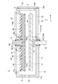
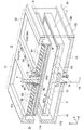
- FIG. 2 is a side sectional view of the plasma CVD apparatus 3, and FIG. 3 is a sectional perspective view thereof.
- the plasma CVD apparatus 3 of this embodiment is configured as a parallel plate type (capacitive coupling type) plasma CVD apparatus, and includes a vacuum chamber 10, an electrode unit 6 including a shower plate 61, and a stage unit for supporting a substrate. 7.
- the vacuum chamber 10 has a length direction in the X direction, a width direction in the Y direction, and a height (thickness) direction in the Z direction.
- the vacuum chamber 10 has a first chamber block 11 and a second chamber block 12.
- the first chamber block 11 and the second chamber block 12 are joined to each other in the Y direction to constitute a vacuum chamber 10 having a processing chamber 8 (internal space) inside.
- Each of the chamber blocks 11 and 12 is formed of a metal material such as stainless steel or an aluminum alloy, and is formed into a polyhedral shape through processing steps such as press molding and welding.
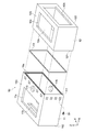
- FIG. 4 is an exploded perspective view of the vacuum chamber 10 showing the first and second chamber blocks 11 and 12 and the seal member 13 mounted between them.
- the first chamber block 11 is formed in a hexahedron shape having a side surface 111 (first side surface) in which an opening 11a (first opening) is formed in a YZ plane orthogonal to the X direction.
- the second chamber block 12 is formed in a hexahedron shape having a side surface 121 (second side surface) in which an opening 12a (second opening) is formed in a YZ plane orthogonal to the X direction. .
- seal member 13 for example, an annular seal part such as an O-ring is used.
- the seal member 13 is mounted between the first side surface 111 and the second side surface 121 to ensure the sealability of the joint portion between the chamber blocks 11 and 12.
- the first chamber block 11 has another side surface 112 (fourth side surface) that faces the side surface 111 in the X direction.
- the side surface 112 is connected to the transfer chamber 2 via the gate valve 4 (FIG. 1).
- an opening 11b for substrate conveyance is formed on the side surface 112.
- the opening 11b is formed in a size that allows the substrate W to pass through, and the substrate W is transferred between the transfer chamber 2 and the vacuum chamber 10 through the opening 11b.
- the first chamber block 11 has a window portion 11c formed on the upper surface 113 thereof.
- the window portion 11c is normally closed by the lid body 21 (FIG. 1) via a seal member, and is opened when the electrode unit 6 (shower plate 61) is installed or removed.
- the lid 21 is attached to the upper surface 113 of the chamber block 11 via a plurality of bolts.
- the second chamber block 12 has another side surface 122 (third side surface) that faces the side surface 121 in the X direction.
- the side surface 122 is provided with an extraction portion 5 (FIG. 1) of the electrode unit 6.
- the take-out unit 5 includes a transport port 12b formed in the side surface 122, and a lid member 23 (FIG. 1) that opens and closes the transport port 12b.
- the conveyance port 12b is formed in a size that allows the electrode unit 6 and the stage unit 7 to pass along the X direction.
- the electrode unit 6 and the stage unit 7 are transported between the inside and the outside of the vacuum chamber 10 through the transport port 12b.
- the transport port 12b is normally closed by the lid member 23, and is opened when the electrode unit 6 is installed or removed.
- the lid member 23 is detachably attached to the side surface 122 via a plurality of bolts.
- the second chamber block 12 has a window portion 12c formed on the upper surface 123 thereof.
- the window portion 12c is normally closed by a lid 22 (FIG. 1) via a seal member (not shown), and is opened when the electrode unit 6 is installed or removed.
- the lid 22 is detachably attached to the upper surface 123 of the chamber block 12 via a plurality of bolts.
- the first chamber block 11 and the second chamber block 12 are joined by a plurality of bolts B1.
- the bolt B ⁇ b> 1 is fastened through a plurality of bolt mounting holes 114 formed around the joint surface of the first chamber block 11.
- the present invention is not limited to this, and flange portions may be formed on the joint surfaces of the first and second chamber blocks 11 and 12, and these flange portions may be joined with bolts.
- the side surface 111 and the side surface 121 can be joined to each other by welding.
- the first chamber block 11 includes a through hole 115 through which the shaft portion 9 for supporting the electrode unit 6 passes, a through hole 116 through which the support shaft 18 for supporting the stage unit 7 passes, and the vacuum chamber 10.
- a connection port (not shown) with an evacuation system for exhausting the internal space is formed.
- an electrode unit 6 and a stage unit 7 are installed in the processing chamber 8 of the vacuum chamber 10.
- the electrode unit 6 and the stage unit 7 are detachably installed with respect to the vacuum chamber 10.
- the electrode unit 6 includes a shower plate 61, an electrode plate 62 (first electrode plate), a dispersion plate 63, and an insulator 64.
- the electrode unit 6 is installed at a predetermined position in the processing chamber 8 through the shaft portion 9.
- the shower plate 61 is typically composed of a flat metal plate, and is opposed to the substrate W on the stage unit 7 with a predetermined distance.
- the shower plate 61 has a plurality of holes 61 a for ejecting process gas at a predetermined flow rate between the electrode unit 6 and the stage unit 7. These holes 61 a are shown in a simplified manner in the drawing, but are formed with a uniform density in the plane of the shower plate 61.
- the size and number of the holes 61a can be set as appropriate, and are not limited to the illustrated example.
- the shower plate 61 is formed in a size that can cover the film formation surface of the substrate W.
- the shower plate 61 has a length penetrating the openings 11 a and 11 b of the chamber blocks 11 and 12 in the processing chamber 8. That is, the length along the X direction of the shower plate 61 is larger than the individual lengths (the lengths in the Y direction) of the first and second chamber blocks 11 and 12, and the length of each chamber block 11 and 12. It is shorter than the total sum.
- the shower plate 61 is rectangular, but may be circular.
- the electrode plate 62 is fixed integrally with the shower plate 61.
- the electrode plate 62 is composed of a metal plate formed in substantially the same shape and size as the shower plate 61.
- a space 62 b having a predetermined volume is formed between the electrode plate 62 and the shower plate 61.
- a through hole 62a that communicates with the space 62b is formed in the substantially central portion of the electrode plate 62.
- the shaft portion 9 is made of a metal material and passes through a through hole 115 formed in the upper surface of the first chamber block 11.
- An electrically insulating cylindrical member 91 is mounted on the outer peripheral surface of the shaft portion 9, thereby ensuring electrical insulation between the chamber block 11 and the shaft portion 9.
- the shaft portion 9 connects between the electrode plate 62 and a control unit 24 that communicates with a high-frequency power source (not shown).
- a lower end portion of the shaft portion 9 is connected to a substantially central portion of the electrode plate 62 via a plurality of bolts B2.
- the shaft portion 9 is movable in the Z direction, for example, and can adjust the relative distance between the shower plate 61 and the stage unit 7.
- the shaft portion 9 is connected to a process gas supply source (not shown), and a gas introduction passage 92 for guiding the process gas to the shower plate 61 is formed in the center portion of the shaft portion 9.
- the gas introduction passage 92 is aligned with the through hole 62a of the electrode plate 62, and introduces the process gas supplied from the supply source to the space 62b through the through hole 62a.
- the dispersion plate 63 is a single or a plurality of plate-like components arranged in the space 62b.
- the dispersion plate 63 is for allowing the process gas introduced into the space 62 b to flow out from the holes 61 a of the shower plate 61 evenly.
- the shape, size, number of installations, and the like of the dispersion plate can be appropriately set according to the volume of the space 62b, the size of the holes 61a of the shower plate 61, the formation density, and the gas flow rate.
- the insulator 64 is for ensuring electrical insulation between the electrode unit 6 and the vacuum chamber 10, and is provided between the electrode plate 62 and the inner surface of the upper wall of the vacuum chamber 10.
- the insulator 64 is in contact with the inner surface of the upper wall of the vacuum chamber 10, but is not limited thereto, and may be opposed to the inner surface of the upper wall of the vacuum chamber 10 with a certain gap.
- the stage unit 7 includes a stage 71 (second electrode plate) that faces the shower plate 61 in the Z direction, and a heater 72 that heats the stage 71 to a predetermined temperature.
- the stage unit 7 is installed in the processing chamber 8 via, for example, a support shaft 18 connected to a ground potential.
- the stage 71 is made of a metal material and has a size that can support the entire substrate W.
- the stage 71 is electrically connected to the support shaft 18 and is configured as a counter electrode of the electrode plate 62.
- the heater 72 covers almost the entire area of the side periphery and the bottom of the stage 71.
- the heater 72 typically includes a resistance heating source.
- the stage unit 7 and the support shaft 18 are detachably connected via a coupling portion 19.
- the coupling portion 19 can be configured by a coupling mechanism that mechanically or electromagnetically couples the stage unit 7 and the support shaft 18.
- the plasma CVD apparatus 3 of the present embodiment is configured as described above. Next, a method for assembling the plasma CVD apparatus 3 will be described.
- the side surface 111 having the opening 11a of the first chamber block 11 and the side surface 121 having the opening 12a of the second chamber block 12 are opposed to each other. Thereafter, the seal member 13 is sandwiched between the side surfaces 111 and 121 of the chamber blocks 11 and 12, and the first chamber block 11 and the second chamber block 12 are joined to each other with a plurality of bolts B1. Thereby, the vacuum chamber 10 in which the processing chamber 8 is formed is configured.
- the attachment of the shaft portion 9 and the support shaft 18 to the through holes 115 and 116 of the first chamber block 11 may be performed before or after the chamber blocks 11 and 12 are joined.
- the electrode unit 6 and the stage unit 7 are loaded into the processing chamber 8 and installed.
- the electrode unit 6 and the stage unit 7 are carried in along the X direction from the transfer port 12 b formed in the side surface 122 of the second chamber block 12.
- the electrode unit 6 carried into the processing chamber 8 is coupled to the shaft portion 9 using a plurality of bolts B2.
- the coupling between the electrode unit 6 and the shaft portion 9 can be performed by the operator through the window portions 11c and 12c of the first and second chamber blocks 11 and 12, respectively.
- the stage unit 7 carried into the processing chamber 8 is coupled to the support shaft 18 via the coupling portion 19.
- the order of assembly of the electrode unit 6 and the stage unit 7 is not particularly limited.
- the plasma CVD apparatus 3 is provided with the take-out portion 5 (transport port 12b) on the side surface 122 on the non-joint surface side of the vacuum chamber 10 having a divided structure, so that the electrode unit 6 is provided via the transport port 12b.
- the stage unit 7 is carried into the processing chamber 8.
- the shower plate 61 can be properly installed in the processing chamber 8 without having a divided structure. Further, since the division of the shower plate is avoided, the process gas can be uniformly irradiated onto the large substrate.
- the windows 11c and 11d and the transfer port 12b of the vacuum chamber 10 are closed by the lids 21 and 22 and the lid member 23, respectively.
- the side surface 112 of the vacuum chamber 10 in which the substrate transport opening 11 b is formed is hermetically fixed to the gate valve 4. As described above, a sealed structure of the processing chamber 8 is ensured.
- the plasma CVD apparatus 3 in the vacuum processing apparatus 1 functions as a film forming chamber for forming a thin film on the surface of the substrate W by the plasma CVD method.
- the window portions 11c and 12 of the chamber blocks 11 and 12 are sealed by the lids 21 and 22, respectively. Further, the transport port 12 b is also sealed by the lid member 23 with respect to the take-out unit 5 of the plasma CVD apparatus 3. Thereby, the internal space (processing chamber 8) of the vacuum chamber 10 can be exhausted or maintained in a predetermined reduced-pressure atmosphere.
- the substrate W is carried into the processing chamber 8 through the gate valve 4 and the opening 11b by the transfer robot installed in the transfer chamber 2.
- the substrate W carried into the processing chamber 8 is placed on the stage 71.
- the gate valve 4 is closed.
- process gas is supplied to the processing chamber 8 via the shower plate 61.
- As the process gas various reactive gases, raw material gases, inert gases, or mixed gases thereof are used.
- plasma of a process gas is generated between the stage 71 as a counter electrode.
- the plasma active species or reaction products generated at this time are deposited on the surface of the substrate W to form a thin film.
- the extraction unit 5 provided in the vacuum chamber 10 can be used to extract the electrode unit 6 from the vacuum chamber 10.
- the shower plate 61 can be taken out without separating the first and second chamber blocks 11 and 12.
- the take-out part 5 (conveying port 12b) is provided on the side surface 122 intersecting with the X direction, the electrode unit 6 can be easily taken out of the chamber by moving in the X direction.
- the lid member 23 constituting the extraction unit 5 of the electrode unit 6 is not limited to the example configured to be separable from the side surface 122 of the vacuum chamber 10. That is, the lid member 23 may be attached to the side surface 122 so as to be slidable or pivotable, and may be configured to open and close the transport port 12b by a sliding operation or a pivoting operation of the lid member 23.
- the shaft portion 9 that supports the electrode unit 6 and the support shaft 18 that supports the stage unit 7 are configured to penetrate the top surface and the bottom surface of the first chamber block 11, respectively.
- the shaft portion 9 and the support shaft 18 may be configured to penetrate the upper surface and the bottom surface of the second chamber block 12.
- the plasma CVD apparatus 3 is configured as a horizontal plasma CVD apparatus that forms a film in a posture in which the substrate W is laid sideways.
- a vertical plasma CVD apparatus for forming a film in a posture in which the substrate W is upright in a substantially vertical direction may be used.
- the stage unit 7 can function as a counter electrode of the electrode unit 6.
Landscapes
- Chemical & Material Sciences (AREA)
- Engineering & Computer Science (AREA)
- Materials Engineering (AREA)
- General Chemical & Material Sciences (AREA)
- Chemical Kinetics & Catalysis (AREA)
- Mechanical Engineering (AREA)
- Metallurgy (AREA)
- Organic Chemistry (AREA)
- Plasma & Fusion (AREA)
- Physics & Mathematics (AREA)
- Analytical Chemistry (AREA)
- Chemical Vapour Deposition (AREA)
- Plasma Technology (AREA)
- Physical Vapour Deposition (AREA)
Abstract
Description
上記第1のチャンバブロックは、第1の側面と、第2の側面とを有する。上記第1の側面は、第1の方向と交差する第1の開口を有する。上記第2の側面は、基板を通過させるための第1の搬送口を有する。
上記第2のチャンバブロックは、第3の側面と、第4の側面とを有する。上記第3の側面は、上記第1の方向と交差する第2の開口を有する。上記第4の側面は、上記第1の方向において上記第3の側面に対向する。上記第2のチャンバブロックは、上記第3の側面が上記第1の側面と接合されることで、上記第1及び第2の開口を含む真空排気可能な内部空間を形成する。
上記シャワープレートは、上記第1のチャンバブロックの上記第1の方向に沿う第1の長さ及び上記第2のチャンバブロックの上記第1の方向に沿う第2の長さよりも大きく、かつ、上記第1の長さと上記第2の長さの和よりも小さい第3の長さを有する。上記シャワープレートは、上記第3の長さ方向を上記第1の方向と平行にして上記内部空間に配置される。
上記取出し部は、上記内部空間から上記シャワープレートを搬出入するためのものであり、上記第4の側面に設けられる。
上記第1のチャンバブロックは、第1の方向と交差する第1の開口が形成された第1の側面を有する。
上記第2のチャンバブロックは、第2の側面と、第3の側面とを有する。上記第2の側面は、上記第1の方向と交差する第2の開口を有する。上記第3の側面は、上記第1の方向において上記第2の側面に対向する。上記第2のチャンバブロックは、上記第2の側面が上記第1の側面と接合されることで、上記第1及び第2の開口を含む真空排気可能な内部空間を形成する。
上記シャワープレートは、上記第1及び第2の開口を貫通するように上記内部空間に配置される。
上記取出し部は、上記内部空間から上記シャワープレートを上記第1の方向に沿って取り出すためのものであり、上記第3の側面に設けられる。
これにより、取出し部の構成を簡素化でき、蓋部材を開閉するだけでシャワープレートの搬送作業を実行することができる。蓋部材は、機械式あるいは電磁式に開閉するバルブで構成することも可能である。
この構成により、第1の電極プレートと軸部材との連結操作及びその解除操作によって、内部空間へのシャワープレートの取り付け及び取り外しを行うことが可能となる。
第2の電極プレートは、基板を支持するステージとして用いることができる。第2の電極プレートは、基板を所定温度に加熱するヒータを内蔵してもよい。
これにより、シャワープレートのみならず、第2の電極プレートの取り外し作業も容易に行うことが可能となる。
これにより、上記開口部を介して真空チャンバの内部空間に基板を搬送することが可能となる。
2…搬送室
3…プラズマCVD装置
4…ゲートバルブ
5…取出し部
6…電極ユニット
7…ステージユニット
8…処理室(内部空間)
9…軸部
10…真空チャンバ
11…第1のチャンバブロック
11a、12a…開口(第1、第2の開口)
11b…開口部
12b…搬送口
11c、12c…窓部
12…第2のチャンバブロック
13…シール部材
18…支持軸
19…結合部
21、22…蓋体
23…蓋部材
61…シャワープレート
62…電極プレート
71…ステージ
72…ヒータ
Claims (6)
- 第1の方向と交差する第1の開口が形成された第1の側面を有する第1のチャンバブロックと、
前記第1の方向と交差する第2の開口が形成された第2の側面と、前記第1の方向において前記第2の側面に対向する第3の側面とを有し、前記第2の側面が前記第1の側面と接合されることで、前記第1及び第2の開口を含む真空排気可能な内部空間を形成する第2のチャンバブロックと、
前記第1及び第2の開口を貫通するように前記内部空間に配置されたシャワープレートと、
前記第3の側面に設けられ、前記内部空間から前記シャワープレートを前記第1の方向に沿って取り出すための取出し部と
を具備するプラズマCVD装置。 - 請求項1に記載のプラズマCVD装置であって、
前記取出し部は、
前記第3の側面に形成され前記シャワープレートが通過可能な搬送口と、
前記搬送口を開閉自在な蓋部材とを有する
プラズマCVD装置。 - 請求項2に記載のプラズマCVD装置であって、
前記シャワープレートと一体的に取り付けられた第1の電極プレートと、
前記第1のチャンバブロック又は前記第2のチャンバブロックを貫通し、前記第1の電極プレートに対して着脱自在に連結された軸部材とをさらに具備する
プラズマCVD装置。 - 請求項3に記載のプラズマCVD装置であって、
前記基板を支持し、前記第1及び第2の開口を貫通するように前記内部空間に配置され、前記第1の方向と直交する第2の方向において前記シャワープレートと対向する第2の電極プレートをさらに具備する
プラズマCVD装置。 - 請求項4に記載のプラズマCVD装置であって、
前記搬送口は、前記第2の電極プレートが通過可能な大きさに形成されている
プラズマCVD装置。 - 請求項1に記載のプラズマCVD装置であって、
前記第1のチャンバブロックは、基板搬送用の開口部が形成された第4の側面をさらに有し、
前記第4の側面は、前記第1の側面と前記第1の方向において対向する
プラズマCVD装置。
Priority Applications (3)
| Application Number | Priority Date | Filing Date | Title |
|---|---|---|---|
| JP2010546584A JP5309161B2 (ja) | 2009-01-14 | 2010-01-12 | プラズマcvd装置 |
| CN201080004227.3A CN102272350B (zh) | 2009-01-14 | 2010-01-12 | 等离子cvd装置 |
| KR1020117013488A KR101338629B1 (ko) | 2009-01-14 | 2010-01-12 | 플라스마 cvd 장치 |
Applications Claiming Priority (2)
| Application Number | Priority Date | Filing Date | Title |
|---|---|---|---|
| JP2009006104 | 2009-01-14 | ||
| JP2009-006104 | 2009-01-14 |
Publications (1)
| Publication Number | Publication Date |
|---|---|
| WO2010082467A1 true WO2010082467A1 (ja) | 2010-07-22 |
Family
ID=42339720
Family Applications (1)
| Application Number | Title | Priority Date | Filing Date |
|---|---|---|---|
| PCT/JP2010/000106 Ceased WO2010082467A1 (ja) | 2009-01-14 | 2010-01-12 | プラズマcvd装置 |
Country Status (5)
| Country | Link |
|---|---|
| JP (1) | JP5309161B2 (ja) |
| KR (1) | KR101338629B1 (ja) |
| CN (1) | CN102272350B (ja) |
| TW (1) | TWI419993B (ja) |
| WO (1) | WO2010082467A1 (ja) |
Cited By (1)
| Publication number | Priority date | Publication date | Assignee | Title |
|---|---|---|---|---|
| JP2018133464A (ja) * | 2017-02-16 | 2018-08-23 | 東京エレクトロン株式会社 | 真空処理装置、及びメンテナンス装置 |
Families Citing this family (3)
| Publication number | Priority date | Publication date | Assignee | Title |
|---|---|---|---|---|
| US8900403B2 (en) | 2011-05-10 | 2014-12-02 | Lam Research Corporation | Semiconductor processing system having multiple decoupled plasma sources |
| KR101947844B1 (ko) * | 2011-05-10 | 2019-02-13 | 램 리써치 코포레이션 | 다수의 디커플링된 플라즈마 소스들을 갖는 반도체 프로세싱 시스템 |
| CN121171865A (zh) * | 2024-06-18 | 2025-12-19 | 中微半导体设备(上海)股份有限公司 | 喷淋头组件、沉积装置及其安装方法 |
Citations (4)
| Publication number | Priority date | Publication date | Assignee | Title |
|---|---|---|---|---|
| JP2006137995A (ja) * | 2004-11-12 | 2006-06-01 | Ulvac Japan Ltd | 真空チャンバ |
| JP2007067218A (ja) * | 2005-08-31 | 2007-03-15 | Tokyo Electron Ltd | 基板処理装置および基板処理システム |
| JP2007073542A (ja) * | 2005-09-02 | 2007-03-22 | Tokyo Electron Ltd | 真空チャンバおよび真空処理装置 |
| JP2009302106A (ja) * | 2008-06-10 | 2009-12-24 | Tokyo Electron Ltd | チャンバ及び処理装置 |
Family Cites Families (3)
| Publication number | Priority date | Publication date | Assignee | Title |
|---|---|---|---|---|
| JP4353601B2 (ja) * | 2000-01-04 | 2009-10-28 | 株式会社アルバック | プラズマcvd装置 |
| JP2007019284A (ja) * | 2005-07-08 | 2007-01-25 | Sony Corp | プラズマcvd装置及び薄膜形成方法 |
| JP4916220B2 (ja) * | 2006-05-31 | 2012-04-11 | 東京エレクトロン株式会社 | プラズマ処理装置及びそれに用いられる電極 |
-
2010
- 2010-01-12 JP JP2010546584A patent/JP5309161B2/ja active Active
- 2010-01-12 KR KR1020117013488A patent/KR101338629B1/ko active Active
- 2010-01-12 WO PCT/JP2010/000106 patent/WO2010082467A1/ja not_active Ceased
- 2010-01-12 CN CN201080004227.3A patent/CN102272350B/zh active Active
- 2010-01-13 TW TW099100799A patent/TWI419993B/zh active
Patent Citations (4)
| Publication number | Priority date | Publication date | Assignee | Title |
|---|---|---|---|---|
| JP2006137995A (ja) * | 2004-11-12 | 2006-06-01 | Ulvac Japan Ltd | 真空チャンバ |
| JP2007067218A (ja) * | 2005-08-31 | 2007-03-15 | Tokyo Electron Ltd | 基板処理装置および基板処理システム |
| JP2007073542A (ja) * | 2005-09-02 | 2007-03-22 | Tokyo Electron Ltd | 真空チャンバおよび真空処理装置 |
| JP2009302106A (ja) * | 2008-06-10 | 2009-12-24 | Tokyo Electron Ltd | チャンバ及び処理装置 |
Cited By (1)
| Publication number | Priority date | Publication date | Assignee | Title |
|---|---|---|---|---|
| JP2018133464A (ja) * | 2017-02-16 | 2018-08-23 | 東京エレクトロン株式会社 | 真空処理装置、及びメンテナンス装置 |
Also Published As
| Publication number | Publication date |
|---|---|
| KR20110084530A (ko) | 2011-07-25 |
| CN102272350A (zh) | 2011-12-07 |
| CN102272350B (zh) | 2014-12-24 |
| TW201033395A (en) | 2010-09-16 |
| TWI419993B (zh) | 2013-12-21 |
| JPWO2010082467A1 (ja) | 2012-07-05 |
| KR101338629B1 (ko) | 2013-12-06 |
| JP5309161B2 (ja) | 2013-10-09 |
Similar Documents
| Publication | Publication Date | Title |
|---|---|---|
| JP5189609B2 (ja) | プラズマ処理装置 | |
| US10190214B2 (en) | Deposition apparatus and deposition system having the same | |
| CN101743610B (zh) | 平面基板的处理装置 | |
| CN101325169B (zh) | 载置台和使用该载置台的等离子体处理装置 | |
| US7534301B2 (en) | RF grounding of cathode in process chamber | |
| CN109314034B (zh) | 真空处理室及制造真空处理的板形基底的方法 | |
| JPWO2000075972A1 (ja) | 真空処理装置 | |
| CN107615459B (zh) | 等离子体原子层生长装置 | |
| CN102142357A (zh) | 等离子处理装置 | |
| CN203639553U (zh) | 具有流量阀门的负载锁定腔室及用于形成器件的装置 | |
| JP5309161B2 (ja) | プラズマcvd装置 | |
| CN107615460A (zh) | 原子层生长装置 | |
| JP4679051B2 (ja) | Cvd装置 | |
| TW201028629A (en) | Heat treatment device | |
| JPH11260881A (ja) | 処理装置 | |
| JP6567886B2 (ja) | プラズマ処理装置 | |
| KR101514108B1 (ko) | 챔버 및 처리 장치 | |
| JP7108347B2 (ja) | 成膜装置 | |
| KR20060047678A (ko) | 성막장치 및 성막장치를 사용하는 성막시스템 | |
| JP6557523B2 (ja) | プラズマ処理装置 | |
| JP5896630B2 (ja) | 真空容器、真空容器の製造方法 | |
| US20050150458A1 (en) | Reduced volume reactor | |
| JP5293220B2 (ja) | 成膜装置 | |
| JP6969373B2 (ja) | プラズマ処理装置 | |
| CN102117735A (zh) | 狭缝阀隧道支撑件 |
Legal Events
| Date | Code | Title | Description |
|---|---|---|---|
| WWE | Wipo information: entry into national phase |
Ref document number: 201080004227.3 Country of ref document: CN |
|
| 121 | Ep: the epo has been informed by wipo that ep was designated in this application |
Ref document number: 10731138 Country of ref document: EP Kind code of ref document: A1 |
|
| ENP | Entry into the national phase |
Ref document number: 20117013488 Country of ref document: KR Kind code of ref document: A |
|
| ENP | Entry into the national phase |
Ref document number: 2010546584 Country of ref document: JP Kind code of ref document: A |
|
| NENP | Non-entry into the national phase |
Ref country code: DE |
|
| 122 | Ep: pct application non-entry in european phase |
Ref document number: 10731138 Country of ref document: EP Kind code of ref document: A1 |