WO2010082273A1 - 中空ニードル及びその製造方法 - Google Patents
中空ニードル及びその製造方法 Download PDFInfo
- Publication number
- WO2010082273A1 WO2010082273A1 PCT/JP2009/006830 JP2009006830W WO2010082273A1 WO 2010082273 A1 WO2010082273 A1 WO 2010082273A1 JP 2009006830 W JP2009006830 W JP 2009006830W WO 2010082273 A1 WO2010082273 A1 WO 2010082273A1
- Authority
- WO
- WIPO (PCT)
- Prior art keywords
- hollow needle
- liquid
- needle
- hole
- holding
- Prior art date
- Legal status (The legal status is an assumption and is not a legal conclusion. Google has not performed a legal analysis and makes no representation as to the accuracy of the status listed.)
- Ceased
Links
Images




Classifications
-
- B—PERFORMING OPERATIONS; TRANSPORTING
- B41—PRINTING; LINING MACHINES; TYPEWRITERS; STAMPS
- B41J—TYPEWRITERS; SELECTIVE PRINTING MECHANISMS, i.e. MECHANISMS PRINTING OTHERWISE THAN FROM A FORME; CORRECTION OF TYPOGRAPHICAL ERRORS
- B41J2/00—Typewriters or selective printing mechanisms characterised by the printing or marking process for which they are designed
- B41J2/005—Typewriters or selective printing mechanisms characterised by the printing or marking process for which they are designed characterised by bringing liquid or particles selectively into contact with a printing material
- B41J2/01—Ink jet
- B41J2/17—Ink jet characterised by ink handling
- B41J2/175—Ink supply systems ; Circuit parts therefor
Definitions
- a method of applying a liquid repellent treatment to the inner and outer surfaces of the needle by a photolithography process at the tip of the hollow glass needle (hereinafter referred to as a liquid volume regulating hollow needle method) is a non-patent document. 1 is proposed.
- a liquid volume regulating hollow needle method By soaking the tip of the needle in a liquid tank, the liquid is wetted by capillary action and is always filled in the needle as long as the liquid repellent treatment inside the hole is not performed. If the liquid is ejected after filling, the liquid can be applied to the object without causing liquid residue by the liquid repellent treatment on the outer surface of the needle.
- the conventional method sometimes has a problem in supplying a small amount of coating without variation.
- the amount of liquid material to be applied is extremely small, and there may be a case where a coating amount of several picoliters to several hundred picoliters is required.
- a liquid material filled in a syringe is pressurized by a piston or screw and discharged from a hollow needle.
- the discharge amount is controlled by the movement amount of the piston, for example, when 100 picoliter is discharged when the inner diameter of the syringe is 5 mm, the movement amount of the piston is about 5 nm, which is difficult to realize.
- the needle diameter is 50 ⁇ m and the material filled in the needle is pushed out by pulse air or the like, the change of about 50 ⁇ m is controlled at the liquid filling position in the needle, and it is difficult to ensure the discharge accuracy.
- a tiny amount of liquid can be applied by applying a lyophilic process to the tip of the pin and a liquid repellent process in addition to it.
- a lyophilic process to the tip of the pin and a liquid repellent process in addition to it.
- the size of the meniscus of the liquid material formed at the tip of the pin changes, and it is difficult to suppress variation in the coating amount with good reproducibility.
- Mass-produced products such as syringes, needles, pistons and supply control devices used in the dispensing method are commercially available and can be obtained at low cost.
- inkjet heads and the like are relatively easily available.
- a needle in the pin transfer system may require a film forming process when performing a liquid repellent treatment or the like, but can be manufactured relatively easily if the process is performed on the outer surface of the pin.
- the liquid volume regulating hollow needle method requires a plurality of needle film forming steps.
- the liquid when the tip of the hollow needle is attached to the liquid tank, the liquid is sucked up by a capillary phenomenon generated in the lyophilic hole of the holding portion provided at the tip of the hollow needle, and the liquid repellent film outside the hole
- a certain amount of droplets can be automatically secured accurately.
- the liquid by supplying air to the inside of the hollow needle, it is possible to stably transfer the filled accurate amount of liquid to the application target.
- FIG. 1 shows a cross-sectional view of a coating needle showing one embodiment of the present invention, and a filling method and a coating method of a liquid material 4.
- a liquid volume regulating needle 10 is constituted by a glass needle body 1 that is a hollow pipe and a cylindrical holding portion 2 that holds the liquid material 4.
- the needle body 1 may be selected in any way other than glass as long as sufficient strength and durability can be obtained, such as a metal material, a resin material, and ceramics.
- this hole has a diameter of several ⁇ m and an aspect ratio of less than 10, it can be precisely machined with a drill.
- the filling amount of the liquid material 6 can be managed by the length of 2.
- the surface of the holding part 2 other than the through-hole 4 is provided with a liquid-repellent film 3a, but this film 3a may be omitted as shown in FIG.
- the holding part 2 is inserted inside the needle body 1.
- chamfering may be performed on the hole opening and the upper portion of the holding member as shown in FIG. 5.
- an adhesive may be used as long as the liquid material 6 does not cause a chemical reaction.
- the outer diameter of the holding portion 2 can be made larger than the inner diameter of the needle body 1, and can be fixed by shrink fitting or cold fitting.
- the needle body 1 may be temporarily softened by heating or the like and the holding portion 2 may be fused.
- the fixing of both is airtight so that the holding part 2 does not pop out due to pressure when air is finally poured into the needle body 1 or the compressed air 8 does not leak from the fitting part (fixing part) of both. If it is, it does not need to be based on said fixing method.
- the through hole 4 penetrates both sides of the fixing part.
- the holding unit 2 be fixed to a region including the tip of the hollow needle body 1 because the liquid can be easily filled.
- the use of the liquid volume regulating needle 10 according to the present invention will be described.
- the liquid quantity regulating needle 10 When the liquid quantity regulating needle 10 is immersed in a liquid tank (not shown) in which a liquid material is stored, the liquid rises through the hole 4 by capillary action, and a meniscus 7 is formed on the upper portion of the holding part 2.
- the difference between the contact angle of the liquid repellent coating 3 inside the needle body 1 and the contact angle of the holding portion 2 is 90 ° or more.
- the size (diameter and length) of the through-hole 4 is a size that fills the entire inside of the through-hole 4 by capillary action, and is specifically several hundred nm to 1 ⁇ m. By doing so, the liquid material 6 wetted by the capillary phenomenon does not rise from the holding part 2 to the needle body 1, and the liquid amount is automatically regulated.
- the liquid material 6 filled in the liquid volume regulating needle 10 by blowing compressed air (air) 9 into the needle body 1.
- a liquid repellent film 3 a may be applied to the upper and lower end faces of the holding part 2.
- the hole 4 may be opened after the liquid repellent coating 3a is formed on the entire outer surface of the holding portion 2.
- the liquid repellent coating 3a also reduces the upper and lower meniscuses of the holding member 2, the amount of the liquid material 8 filled in the holes becomes more dominant.
- a liquid repellency part and a lyophilic part can be incorporated into a hollow needle body that has been subjected to liquid repellency as a whole without using a complicated photolithography process.
- By controlling the processing accuracy of only the size of the holding part it is possible to manufacture a liquid volume-regulated hollow needle with little individual difference, and the liquid volume can be accurately measured.
- an opaque material other than glass can be selected as the material for the hollow needle.
- the liquid repellent treatment is applied to the outer surface of the hollow needle, it is possible to suppress the wetting of the liquid and to apply an accurate amount.
- the holding part is also subjected to a liquid repellent treatment other than the holes, liquid separation is improved during application, and application accuracy is further improved.
- the liquid can be filled more stably. if a material such as lyophilic ceramics is selected as the material for the holding member and the end surface of the hollow needle or holding part is coated with fluorine-based organic matter or plating, the liquid can be filled more stably. .
- Embodiment of the liquid quantity regulation needle 10 concerning Example 2 is shown.
- Example 1 since the needle body 1 is subjected to water repellency treatment on the surface, it is effective when it is formed of a material that does not have liquid repellency or lacks liquid repellency.
- the needle body 1 is formed of a material having strong liquid repellency such as Teflon (registered trademark) resin or a resin or metal kneaded with such a material, as shown in FIG. The same effect can be obtained without applying the protective film 3 to the surface.
- Teflon registered trademark
- FIG. 7A the defect 31 on the substrate 30 is detected and laser processing is performed.
- FIG. 7B film formation is performed on the portion 33 subjected to laser processing.
- basic control according to the program is performed by the main control device 50, and for individual operations and device control, a positioning control unit 52, an image detection unit 53, a laser processing unit 54, which are positioned below the main control device 50, The pneumatic control unit 55 performs this.
- the substrate 30 is mounted on the surface plate 40 and fixed.
- a positioning pin or the like is provided on the surface plate 40, and rough positioning is performed by pressing the end face of the substrate.
- the substrate may be fixed by providing holes or grooves that can be vacuum-adsorbed on the surface plate.
- the laser processing unit controls the operation of the laser transmitter 18 and the diaphragm 17 to adjust the optimum wavelength, output, and irradiation range for each material and thickness of the film to be processed.
- the laser irradiation range 33 needs to be within a range where defects can be accommodated or wider than that, and should be within a range that can be properly applied with a single application liquid amount of the liquid amount regulating needle 10. Considering the wetting and spreading of the liquid material 6, it is better to have a circular shape. After removing the defective portion 31 and its periphery by laser irradiation, the liquid material 6 shown in FIG. 7B is applied.
- the liquid amount regulating needle of the present invention is useful for pinpoint application of liquefied material in, for example, correction of wiring patterns of PDP panels, correction of TFT patterns of liquid crystal panels, organic EL panels, or color filters of liquid crystal panels. It is.
Landscapes
- Coating Apparatus (AREA)
- Optical Filters (AREA)
- Electroluminescent Light Sources (AREA)
- Liquid Crystal (AREA)
Abstract
中空ニードル(10)において、孔内表面が親液性である貫通孔(4)を有する円柱状の保持部(2)を、中空ニードル本体(1)先端に有するものである。 当該中空ニードル(10)の先端を液壷に浸すことにより、保持部(2)の貫通孔(4)に定量の液体を保持でき、また中空ニードル(10)の内部に圧空を吹き込むことにより、貫通孔(4)に保持した液体を吐出し、対象物に塗布できる。
Description
本発明は、液晶パネル等の表示装置の製造工程において、パターンの欠陥個所の修正を行う際に微小な領域に液状材料を一定量安定供給する手段である中空ニードルを低コストかつ安定的に提供するものである。これにより修正個所に液体材料を塗布し、適宜乾燥させることで、局所成膜するものである。
テレビ用途の液晶パネル等の表示装置では、市場の要求により、対角寸法で30,40インチ以上のパネルの面積が拡大してきている。一方、成膜段階でのパネル面積当たりの不良発生率を劇的に削減することは現状難しい。このため、安定した液晶パネルの供給には成膜段階での製品不良の救済策が不可欠である。
液晶パネルの場合を例に示すと、不良個所のパターンの修正を施し、不良製品の救済を施す方法として、特許文献1に示されるような方法が提案されている。フォトリソ工程で生じた画素パターンの欠陥部にレーザ光を照射し欠陥部とその周辺部分の膜を除去する。その後、レーザ照射個所に対して、液状化した薄膜材料を滴下、乾燥させて、局所的に成膜する。この液状化材料は一般的に薄膜材料を溶媒に溶かして作られる。
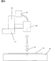
液状材料を塗布する際に、大きく分けて3つの方法が普及している。1つは、特許文献2で提案されるようなシリンジに蓄えられた材料に圧力をかけ、中空ニードルから材料を供給するディスペンス方式である。もう一つは特許文献1または3で提案されるような微小な液滴をヘッドで形成し、放出するインクジェット方式である。他の方法として、特許文献4で提案されるようなニードルの先端に液溜りを作り、ニードルを基板に接触させることで、液を基板に転写するピン転写方式がある。
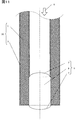
その他の方法として、中空ガラスニードルの先端において、孔の所定深さの領域を除き、ニードルの内外面にフォトリソプロセスで撥液処理を施す方式(以下、液量規定中空ニードル方式)が非特許文献1に提案されている。このニードルの先端を液壷に浸すことにより、液は孔内部の撥液処理を施されていない範囲で、毛細管現象で液の濡れ上がり、常にニードル内部に充填される。充填後、液を噴出せばニードル外面の撥液処理により、液残りを生じず、対象に液を塗布することができる。
日本機械学会第14回バイオエンジニアリング講演会(BE2002)講演論文集, No. 02-04, pp. 207-208, 2002年3月
液体塗布の対象となる表示パネルは高精細化が進み、日増しに露光パターンの微細化が進んでいる。このため、欠陥修正時のレーザ光による除去加工領域及び液状材料の塗布領域も微細化が要求され、数~数百ピコリットル程度の塗布量も必要となるケースが生じてくる。なお、レーザでパターンの除去加工を行った領域に対して過剰な液状材料の塗布を行った場合、乾燥後に除去する必要が生じたり、逆に不足する場合は、断線等の不具合が生じる。また、液を塗布する位置が正確でないと濡れ広がる時にレーザ加工した部分を全て覆いきれない、あるいは、目的以外の場所に膜を形成し、後で除去しなくてはならないなどの不具合が生じる。以上に述べたように、表示パネルの修正では(1)微少量の液滴を、ばらつきを抑えて供給すること、(2)必要な位置に正確に塗布することが求められる。さらに、(3)上記を達成する手段が、単純な製作方法で効率よく製作できることも必要である。
基板上の薄膜パターンの欠陥修正を行う際に、液状材料の塗布可能な量を基準にレーザを照射し、その後液状材料を塗布して修正する場合について従来の方法での技術課題を示す。
従来の方法では微量な塗布量をばらつき無く供給することに問題が生じることもあった。精細なパターンに対する修正において、塗布する液状材料は極めて微量であり、数ピコリットル~数100ピコリットルの塗布量が要求されるケースも考えられる。
ディスペンス方式ではシリンジに充填された液状材料をピストンまたはスクリューにより圧力を付加し、中空のニードルから吐出するものである。ピストンの移動量で吐出量を制御する場合、例えば、シリンジの内径が5mmで100ピコリットルを吐出する場合、ピストンの移動量は5nm程度となり、実現が困難である。また、ニードル径を50μmとして、ニードルに充填した材料を、パルスエア等で押し出す方法にしても、ニードル内の液充填位置で50μm程度の変化を制御することになり、吐出精度の確保が難しい。
ピン転写方式では、ピンの先端に親液加工、それ以外に撥液加工を施すことにより、微小量の液を塗布することが可能になる。しかし、液壷へのピンの浸し方により、ピン先端に形成される液状材料のメニスカスの大きさが変化し、再現性よく、塗布量のばらつきを抑えることが困難であった。
この点、インクジェット方式や液量規定ニードル方式は微量の液滴を一定量供給することは可能である。
次に、従来の方式における塗布位置に関する課題を以下に示す。
基本的にディスペンス方式、ピン転写方式、液量規定中空ニードル方式は塗布位置を画像処理等で計測後、xyzステージなどの手段により、目標位置に液供給手段を移動し、ニードルやピンを塗布対象の基板に接近または接触させて液体を塗布する。この時のステージ移動精度、つまり塗布位置の精度は一般に高精度を実現しやすい。一方、インクジェット方式では、液滴を放出する際、放出角度のばらつきや、供給ヘッド周辺の気流等の影響を受け、精度が劣化し易いという問題があった。
最後に従来の方式における液供給手段の製作方法についての課題を示す。
ディスペンス方式に用いるシリンジ,ニードル,ピストンや供給制御機器などは量産品が市販されており、安価に入手可能である。同様にインクジェットヘッドなども比較的容易に入手可能である。ピン転写方式でのニードルは撥液処理などを施す場合、成膜工程が必要になる場合があるが、ピンの外面への処理であれば、比較的容易に製作可能である。しかし、液量規定中空ニードル方式では、ニードルの複数回の成膜工程が必要である。細いガラス管を作る際、ガラス管を加熱、溶解させ、軸方向に引っ張り、切断する。こうして得られた細いガラス管の先端は、数°程度の傾きを有するテーパー状になる。この状態で成膜し、露光しようとすると、露光光をガラス面に対して直角に入射させることが困難で、斜めに入射した露光光波はガラスの中を広い範囲で伝播するため、感光性レジストにマスキングを掛けて露光範囲の限定が困難である。つまり、撥液性を持たせない領域の範囲にばらつきを生じる可能性がある。すなわち、1本のニードルでは充填する液滴のばらつきを低減できても、ニードル自体に個体差があり、ニードル交換毎に調整が必要となる問題が生じた。
そこで、本発明では、ディスペンス方式やピン転写方式のようにステージ精度で塗布位置の高精度化を図れる塗布方法において、微少量塗布する液体を安定して一定量供給し、部材の個体差を生じない塗布手段を提供することを目的とする。
本発明は、上記課題を解決するための、中空の中空ニードル本体と、前記中空ニードルの中空内に設けられ、孔内の表面が親液性である貫通孔を有する保持部とを備えた中空ニードルを提供する。
本発明によれば、中空ニードルの先端を液壷に付ければ、中空ニードルの先端に設けた保持部の親液性の孔で生じる毛細管現象での液の吸い上げ、孔の外部の撥液皮膜によりメニスカス形成により、自動的に一定量の液滴を正確に確保することができる。その後、中空ニードルの内部にエアを供給することで、充填した正確な量の液を塗布対象に安定して移すことが可能である。
以下では本発明に係る実施例を図を用いて説明する。
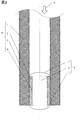
図1は、本発明の1形態を示す塗布用ニードルの断面図と、液状材料4の充填、塗布方法を示す。中空パイプであるガラス製のニードル本体1と液状材料4を保持する円柱状の保持部2より液量規定ニードル10が構成される。
ニードル本体1はガラス以外に、金属材料,樹脂材料,セラミックスなど、十分な強度と耐久性が得られれば、どのように選んでも構わない。
ニードル本体1に対しては、端面も含めた全面にわたり、撥液性の皮膜3を形成する。皮膜3の形成方法としては、その分子にフッ素を含む有機物を溶媒に溶き、それをニードル本体1に塗布またはその溶液にニードル本体1を漬け込み、乾燥させて行う。また、表面の皮膜3にめっきを用いても良い。撥液性皮膜3は強い撥液性を示すものであればフッ素を含む有機物にこだわらなくてもよい。また、皮膜3はニードル本体1全体ではなくても、液状材料4が接触しうる箇所(例えば、ニードル本体1の先端付近のみや、ニードル本体1が保持部2に接している部分を除く部分など)に形成していれば足りる。
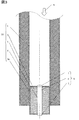
保持部2の材質は液状材料6(例えば、アルコール,アセトン,ヘキサン,NMP,ペグミアなどの有機溶剤で希釈したフォトレジスト,配向膜材料,塗布ITO液,金属錯体など溶液)に対して親液性であり接触角が小さいことが望ましい。この条件に適合すれば、ニードル本体1と同じ材質であることにこだわらず、どのような材質を用いても構わない。例えば、アルミナやジルコニアなどのセラミックス材料を用いてもよいし、金属材料で製作しても構わない。保持部2には少なくとも1つ以上、両底面を貫く孔4を設ける。この孔に液状材料が充填されることになるが、この孔は数μmの直径でアスペクト比10未満であればドリルで精密に加工することが可能であり、孔4の数や直径,保持部2の長さにより液状材料6の充填量を管理できる。保持部2の貫通孔4以外の表面には、發液性の皮膜3aが施されているが、図2に示すようにこの皮膜3aは省略してもよい。
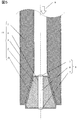
ニードル本体1に対して保持部2は内側に挿入されている。ニードル本体1に保持部2を挿入し易くするために、図5のようにニードル本体1の孔口及び保持部材上部に面取り加工を施しても構わない。両者の固定は液状材料6が化学反応を起こさなければ、接着剤を用いても構わない。接着剤を用いない場合、ニードル本体1の内径よりも保持部2の外径を大きくし、焼きばめ、冷やしばめ等によって固定することができる。また、ニードル本体1を加熱等により一旦軟化させ保持部2を融着しても良い。両者の固定は、最終的にニードル本体1にエアを流し込んだ時に圧力で保持部2が飛び出さない、もしくは、両者のはめあい部分(固定部)から圧空8が漏れ出さないように気密性がとれていれば、上記の固定方法によらなくても良い。保持部2を固定したとき、貫通孔4は固定部の両側に貫通するようになっている。また、保持部2は、中空ニードル本体1の先端を含む領域に固定すると、液の充填がしやすくなるので望ましい。
本発明の中空ニードルの製造方法について説明する。まず、保持部2の基材となる親液性の部材を用意する。この親液性の部材の表面に、必要に応じて撥液性の皮膜3aを成膜し、成膜後に貫通孔4をあけ、保持部2が作製される。表面が發液性または發液処理を行った中空ニードル本体1を用意し、保持部2をニードル本体1の内部に挿入して固定すると、液量規定ニードル10が完成する。
本発明にかかる液量規定ニードル10の使用について説明する。液量規定ニードル10を液状材料が納められた液壷(図示せず)に浸けた時に、毛細管現象で孔4を液が濡れ上がり、保持部2上部にメニスカス7を形成する。取り扱う液状材料6において、ニードル本体1の内部の撥液皮膜3の接触角と保持部2の接触角の差が90°以上あることが望ましい。また、貫通孔4の大きさ(径及び長さ)は、毛細管現象により貫通孔4内全体に液が充填される大きさであり、具体的には数100nm~1μmとなる。このようにすることで、毛細管現象で濡れあがった液状材料6は保持部2からニードル本体1への濡れ上がりが生じず、液量の規定が自動的に行われる。
この機能を有効に活かすためには、液壷への液量規定ニードル10の浸け方も影響する。液量規定ニードル10を液壷に深く浸け過ぎると、水頭差の影響で液量を自動的に規定できなくなるので、液量規定ニードル10の先端が液面に接触する程度、もしくは保持部材2の高さよりも浅く浸ける必要がある。こうすることで、液量規定ニードル10内に毛細管現象を利用して充填する液量を常に一定量に規定することができる。
液壷から液量規定ニードル10を引き上げた時に、保持部2の下部にもメニスカス7を形成する。しかし、ニードル本体1の外側にも撥液皮膜3を施しておけば、液状材料6が濡れ上がることもなく、保持部2の下部に形成するメニスカス7の大きさも一定の大きさになる。保持部2の上下に形成するメニスカス7と孔部に充填した液状材料8の量の合計が、液量規定ニードル10に充填される液の総量となる。
液状材料6を充填後、液量規定ニードル10の先端を塗布対象に近付けて位置決め後、ニードル本体1の内部に圧空(空気)9を吹き込むことで、液量規定ニードル10に充填した液状材料6を塗布する。保持部2下端からの液離れを良くするために、保持部2の上下の端面に撥液皮膜3aを施してもよい。この場合、製作を単純化させるために、保持部2の外面全体に撥液性皮膜3aを形成した後、孔4を開けるようにしてもよい。また、この撥液性皮膜3aにより、保持部材2の上下のメニスカスも小さくなるので、孔に充填された液状材料8の量がより支配的になる。保持部材2の底面の面積に比べて孔開口部の総面積が比較的大きい場合には、図2に示すように保持部2の外面に撥液性皮膜3aを施さなくても構わない。この場合には、上下のメニスカスよりも、孔に充填された液状材料8の量がより支配的になる。
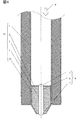
以上に示した図1,図2ではニードル本体1の先端に対して保持部材2の突出はないが、図3,図4に示すように、保持部2を突出させても構わない。また、図4に示すように突出した保持部2に面取りを施しても構わない。なお、保持部2を突出させる場合、その外面に撥液性皮膜3aを施すことが望ましい。
本実施例によれば、中空ニードルの先端を液壷に付ければ、中空ニードルの先端に設けた保持部の親液性の孔で生じる毛細管現象での液の吸い上げ、孔の外部の撥液皮膜によりメニスカス形成により、自動的に一定量の液滴を正確に確保することができる。その後、中空ニードルの内部にエアを供給することで、充填した正確な量の液を塗布対象に安定して移すことが可能である。
また、撥液性を示す部分と親液性示す部分を複雑なフォトリソ工程を用いずに、撥液性を全体に施した中空ニードル本体に、撥液性でない部材を組み込むようにできるので、液保持部の大きさのみの加工精度管理で、個体差の少ない液量規制中空ニードルが製作可能であり、正確に液量を計測することができる。更に、中空ニードルの材料としてガラス以外の不透明な材料を選択することも可能になる。塗布時においては、中空ニードルの外面に撥液処理が施されているため、液の濡れ上がりを抑えることが可能になり正確な量の塗布が可能である。また、本発明で言及するように、保持部においても孔以外に撥液処理を施せば、塗布時に液離れが良くなり、塗布精度も更に向上する。
保持部材の材料として、親液性のあるセラミクス等の材料を選定し、中空ニードルや保持部の端面にフッ素系の有機物やめっきなどが施してあれば、さらに安定した液の充填が可能となる。
液の塗布量を変更する場合には、中空ニードル内部に組み込む保持部材の長さを変更する、つまり孔の長さを変更することにより対応可能である。
実施例2にかかる液量規定ニードル10の実施形態を示す。実施例1ではニードル本体1は、表面に撥水処理を施すので、撥液性を持たないか撥液性が不足している材料で形成されている場合に有効である。しかし、テフロン(登録商標)樹脂などの強力な撥液性を示す材料やそのような材料が混錬された樹脂や金属などでニードル本体1を形成する場合、図6に示すように、撥液性皮膜3を表面に施さなくても同様な効果が得られる。
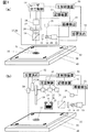
実施例1または2に示した液量規定ニードル10を用いた、基板30上に形成された薄膜の修正を行う装置の一実施例を図7に示す。
図7(a)では、基板30上の欠陥31を検出し、レーザ加工を行う。図7(b)では、レーザ加工を行った個所33に対して、膜形成を行う。この実施例では、プログラムに従った基本的な制御は主制御装置50がおこない、個々の動作や機器の制御についてはその下部に位置する位置決め制御ユニット52、画像検出ユニット53、レーザ加工ユニット54、圧空制御ユニット55が行う。
まず、図7(a)での処理方法を以下に示す。
最初に定盤40上に基板30を載せ固定する。基板30の姿勢をほぼ一定にするため、定盤40には位置決めピンなどを設け、基板の端面を押付けて粗位置決めをしておくとよい。基板の固定は定盤に真空吸着できるような孔または溝を設け、固定すると良い。
その後、画像検知ユニット53は、カメラ13の画像から、基板30上に形成したアライメントマーク32を画像認識し、アライメントマーク32を基準とした座標系の構成を行う。その後、カメラ13で基板30上に形成したパターンをスキャンし、パターンの欠陥31を画像検出ユニット53で検知し、欠陥個所31の位置情報を主制御装置50を介して記憶装置51に記録する。
一通りスキャンが終了した後、パターンの欠陥31が生じている個所にカメラを移動し、レーザ照射を行う。レーザ発信機18や絞り17の操作についてはレーザ加工ユニットが制御を行い、加工対象となる膜の材質、厚さ毎に最適な波長、出力、照射範囲を調整する。レーザの照射範囲33は欠陥が収まるかそれよりも広い範囲とし、液量規定ニードル10の一回の塗布液量で適正に塗布できる範囲とする必要がある。液状材料6の濡れ広がりを考慮すると、円形であると更に良い。レーザ照射により、欠陥個所31およびその周辺を除去したあと、図7(b)に示す液状材料6の塗布を行う。
図7(b)では図7(a)に示した装置と別のステーションで処理する方法と、ヘッドのみを別にして同じ定盤40上で処理する方法が考えられる。以下では、どちらの場合にも当てはまるように説明する。
液量規定ニードル10を液壷25液面に接触させ液状材料6充填する。液壷25は液状材料6の有機溶媒が揮発し、濃度変化が起きないように、液量規定ニードル10が出し入れできる孔が設けられた蓋26を設けることが望ましい。非稼動時には、液量規定ニードル10は液壷の蓋26の孔に差し込まれた状態とし、先端部の乾燥を抑える様にする。
記憶装置51の情報に従い、位置決めユニット52はステージ37.38を駆動し、液量規定ニードル10をレーザ修正範囲33の中心上方に移動する。そこで、基板との高さを光学的に測定する高さセンサ39で、液量規定ニードル10先端と基板30の間隔を狭めて行く。所定の間隔に達したら圧空制御ユニットはバルブ23を開放し、圧空9を液量規定ニードル10内部に送り込む。液離れを良くするために、圧空9を送りながらzステージ38を上昇させるとよい。
以上に示したように液状材料6の塗布が終了後、定盤40に基板を固定したまま温風を吹き付けて、塗布個所34を乾燥させるか、基板30の固定を解除し、基板30を炉に入れて乾燥させる。
本発明の液量規定ニードルは、例えばPDPパネルの配線パターンの修正や液晶パネル,有機ELパネルのTFTパターンあるいは液晶パネルのカラーフィルタの修正において液状化させた材料をピンポイントで塗布するのに有用である。
1…ニードル本体,2…保持部,3…撥液性皮膜,4…貫通孔,6…液状材料,7…メニスカス,8…孔部に充填された液状材料,9…圧空,10…液量規定ニードル,11…圧空供給手段,13…カメラ,14…ハーフミラー,15…フィルタ,16…照明,17…絞り,18…レーザ発信機,19…レンズ,21…コンプレッサ,22…レギュレータ,23…バルブ,25…液壷,26…蓋,30…基板,31…欠陥,32…アライメントマーク,33…レーザ照射範囲,34…塗布範囲,37…xyステージ,38…zステージ,39…高さセンサ,40…定盤,50…主制御装置,51…記憶装置,52…位置決めユニット,53…画像検出ユニット,54…レーザ加工制御ユニット,55…圧空制御ユニット,60…シリンジ,61…ピストン,62…蓋,63…中空ニードル,70…塗布針,71…撥液性皮膜非形成部,72…平坦部,73…液球,80…インクジェットヘッド,81…液状材料タンク,82…射出した液滴。
Claims (12)
- 中空ニードル本体と、
前記中空ニードル端部に設けられ、孔内の表面が親液性である貫通孔を有する保持部とを備えた中空ニードル。 - 請求項1に記載の中空ニードルであって、
前記中空ニードル本体と前記保持部とは、前記ニードル本体の内周側と前記保持部の外周側との間に気密性を有して接続され、
前記貫通孔は、前記保持部の当該接続された部分の両側の面を貫通していることを特徴とする中空ニードル。 - 請求項1または請求項2に記載の中空ニードルであって、
前記中空ニードル本体の内面及び外面が撥液性を有することを特徴とする中空ニードル
。 - 請求項1~3のいずれかに記載の中空ニードルであって、
前記保持部は、前記貫通孔以外の表面に撥液性を有することを特徴とする中空ニードル
。 - 請求項1~4のいずれかに記載の中空ニードルであって、
前記保液部材がセラミクッスで形成されていることを特徴とする中空ニードル。 - 請求項1~5のいずれかに記載の中空ニードルであって、
前記中空ニードル本体は、撥液性を有する材料で形成されていることを特徴とする中空ニードル。 - 請求項1~5のいずれかに記載の中空ニードルであって、
中空ニードル本体の内面及び外面にフッ素を有する有機物でコーティングすることを特徴とする中空ニードル。 - 請求項7において、
前記中空ニードルに対して前記コーティングしたフッ素を有する有機物の層をめっきで形成することを特徴とする中空ニードル。 - 請求項1~8のいずれかに記載の中空ニードルであって、
前記保持部は、前記中空ニードル本体の先端を含む領域に設けられていることを特徴とする中空ニードル。 - 請求項1~9のいずれかに記載の中空ニードルであって、
前記貫通孔は、毛細管現象により、その内部の全体に液を充填可能な大きさであることを特徴とする中空ニードル。 - 親水性を有する材料で形成された部材の表面に撥水処理を施す工程と、
前記撥水処理を施した部材に貫通孔を形成し、保持部とする工程と、
表面に發液性を有する中空ニードル本体の中空内に、前記保持部を挿入する工程とを含む中空ニードルの製造方法。 - 請求項11において、
前記保液部材は、前記中空ニードル本体に気密性を有するように接続され、
前記貫通孔は、前記保持部の前記接続された部分の両側に貫通するように設けられていることを特徴とする中空ニードルの製造方法。
Applications Claiming Priority (2)
| Application Number | Priority Date | Filing Date | Title |
|---|---|---|---|
| JP2009-006208 | 2009-01-15 | ||
| JP2009006208A JP2010162470A (ja) | 2009-01-15 | 2009-01-15 | 中空ニードル及びその製造方法 |
Publications (1)
| Publication Number | Publication Date |
|---|---|
| WO2010082273A1 true WO2010082273A1 (ja) | 2010-07-22 |
Family
ID=42339543
Family Applications (1)
| Application Number | Title | Priority Date | Filing Date |
|---|---|---|---|
| PCT/JP2009/006830 Ceased WO2010082273A1 (ja) | 2009-01-15 | 2009-12-14 | 中空ニードル及びその製造方法 |
Country Status (2)
| Country | Link |
|---|---|
| JP (1) | JP2010162470A (ja) |
| WO (1) | WO2010082273A1 (ja) |
Cited By (2)
| Publication number | Priority date | Publication date | Assignee | Title |
|---|---|---|---|---|
| JP2016503169A (ja) * | 2012-12-26 | 2016-02-01 | ベンタナ メディカル システムズ, インコーポレイテッド | 自動標本処理システムならびに標本担持顕微鏡用スライドガラスを位置合わせおよび輸送する方法 |
| US10746752B2 (en) | 2009-11-13 | 2020-08-18 | Ventana Medical Systems, Inc. | Opposables and automated specimen processing systems with opposables |
Families Citing this family (2)
| Publication number | Priority date | Publication date | Assignee | Title |
|---|---|---|---|---|
| WO2014087629A1 (ja) * | 2012-12-03 | 2014-06-12 | コニカミノルタ株式会社 | ディスペンサー塗布用透光性セラミック材料、及びこれを用いたled装置の製造方法 |
| JP6242122B2 (ja) * | 2013-02-01 | 2017-12-06 | Ntn株式会社 | 塗布ユニットと、それを用いた塗布装置および塗布方法 |
Citations (9)
| Publication number | Priority date | Publication date | Assignee | Title |
|---|---|---|---|---|
| JPH06117970A (ja) * | 1992-10-05 | 1994-04-28 | Fujikura Ltd | 液体供給管の構造 |
| JPH06210187A (ja) * | 1993-01-13 | 1994-08-02 | Fuji Photo Film Co Ltd | 微量定容ピペット |
| JP2003194818A (ja) * | 2001-10-19 | 2003-07-09 | Matsushita Electric Ind Co Ltd | 特異結合分析方法およびこれに用いるデバイス |
| JP2004108862A (ja) * | 2002-09-17 | 2004-04-08 | Ckd Corp | 分注システム |
| JP2006308309A (ja) * | 2005-04-26 | 2006-11-09 | Kyocera Corp | 液状体滴下用ノズル |
| JP2007047003A (ja) * | 2005-08-09 | 2007-02-22 | Olympus Corp | 定量分取具およびその製造方法 |
| JP2007513324A (ja) * | 2003-11-14 | 2007-05-24 | コミサリア、ア、レネルジ、アトミク | 流体状サンプルを受取る装置およびその使用方法 |
| JP2007278937A (ja) * | 2006-04-10 | 2007-10-25 | Olympus Corp | 液体分取具および液体分取装置 |
| JP2007315793A (ja) * | 2006-05-23 | 2007-12-06 | Neat:Kk | 採取液体を検量するために用いられるピペットチップ、このピペットチップを用いた検量方法および検量装置 |
-
2009
- 2009-01-15 JP JP2009006208A patent/JP2010162470A/ja active Pending
- 2009-12-14 WO PCT/JP2009/006830 patent/WO2010082273A1/ja not_active Ceased
Patent Citations (9)
| Publication number | Priority date | Publication date | Assignee | Title |
|---|---|---|---|---|
| JPH06117970A (ja) * | 1992-10-05 | 1994-04-28 | Fujikura Ltd | 液体供給管の構造 |
| JPH06210187A (ja) * | 1993-01-13 | 1994-08-02 | Fuji Photo Film Co Ltd | 微量定容ピペット |
| JP2003194818A (ja) * | 2001-10-19 | 2003-07-09 | Matsushita Electric Ind Co Ltd | 特異結合分析方法およびこれに用いるデバイス |
| JP2004108862A (ja) * | 2002-09-17 | 2004-04-08 | Ckd Corp | 分注システム |
| JP2007513324A (ja) * | 2003-11-14 | 2007-05-24 | コミサリア、ア、レネルジ、アトミク | 流体状サンプルを受取る装置およびその使用方法 |
| JP2006308309A (ja) * | 2005-04-26 | 2006-11-09 | Kyocera Corp | 液状体滴下用ノズル |
| JP2007047003A (ja) * | 2005-08-09 | 2007-02-22 | Olympus Corp | 定量分取具およびその製造方法 |
| JP2007278937A (ja) * | 2006-04-10 | 2007-10-25 | Olympus Corp | 液体分取具および液体分取装置 |
| JP2007315793A (ja) * | 2006-05-23 | 2007-12-06 | Neat:Kk | 採取液体を検量するために用いられるピペットチップ、このピペットチップを用いた検量方法および検量装置 |
Cited By (2)
| Publication number | Priority date | Publication date | Assignee | Title |
|---|---|---|---|---|
| US10746752B2 (en) | 2009-11-13 | 2020-08-18 | Ventana Medical Systems, Inc. | Opposables and automated specimen processing systems with opposables |
| JP2016503169A (ja) * | 2012-12-26 | 2016-02-01 | ベンタナ メディカル システムズ, インコーポレイテッド | 自動標本処理システムならびに標本担持顕微鏡用スライドガラスを位置合わせおよび輸送する方法 |
Also Published As
| Publication number | Publication date |
|---|---|
| JP2010162470A (ja) | 2010-07-29 |
Similar Documents
| Publication | Publication Date | Title |
|---|---|---|
| US11009338B2 (en) | Liquid droplet measurement method and liquid droplet measurement device, and method and apparatus for manufacturing device | |
| US9387562B2 (en) | Device and method for assembling writing head unit | |
| KR100453587B1 (ko) | 액체 방울 토출 헤드의 고정 장치 및 고정 방법과 헤드유닛의 조립 장치 | |
| JP4328614B2 (ja) | マイクロデポジション装置 | |
| TWI244973B (en) | Micro lens and making method thereof, optical device, optical transmitting device, head for laser printer and laser printer | |
| JP3927125B2 (ja) | バイオチップの製造方法 | |
| JP2008264608A (ja) | 液滴塗布装置及び液滴塗布方法 | |
| WO2010082273A1 (ja) | 中空ニードル及びその製造方法 | |
| WO2016199696A1 (ja) | 塗布ユニットおよびそれを用いた塗布装置 | |
| JP2005300940A (ja) | 基板リペア方法並びにリペア装置及びこれを用いてリペアされた基板 | |
| JP4449602B2 (ja) | 液滴吐出装置及び膜パターン形成方法 | |
| CN102481787A (zh) | 喷嘴板保持装置及喷墨头的制造方法 | |
| JP2011033689A (ja) | 塗布方法、塗布ユニット、およびパターン修正装置 | |
| JP2008307455A (ja) | 塗布方法、塗布装置、微細欠陥修正装置 | |
| JP2008221183A (ja) | 液滴噴射塗布装置及び塗布体の製造方法 | |
| CN100570439C (zh) | 涂敷机构及涂敷方法、缺陷修正装置及缺陷修正方法 | |
| JP2010064014A (ja) | 塗布ユニットおよびそれを用いたパターン修正装置 | |
| JP2006113127A (ja) | 修正装置 | |
| US20120205782A1 (en) | Imprint Apparatus, Imprint Method, and Process Condition Selection Method | |
| US20080206482A1 (en) | Droplet jetting applicator and method of manufacturing coated body | |
| JP2010082614A (ja) | 塗布装置と、これを用いたパターン修正装置およびパターン修正方法 | |
| JP2012192562A (ja) | 印刷装置 | |
| JP6868844B2 (ja) | 液滴測定方法 | |
| KR20180051546A (ko) | 도포 방법 | |
| JP2007163609A (ja) | パターン形成方法及び液滴吐出装置 |
Legal Events
| Date | Code | Title | Description |
|---|---|---|---|
| 121 | Ep: the epo has been informed by wipo that ep was designated in this application |
Ref document number: 09838243 Country of ref document: EP Kind code of ref document: A1 |
|
| NENP | Non-entry into the national phase |
Ref country code: DE |
|
| 122 | Ep: pct application non-entry in european phase |
Ref document number: 09838243 Country of ref document: EP Kind code of ref document: A1 |