WO2010067732A1 - 研磨装置、及び研磨方法、並びにガラス板の製造方法 - Google Patents
研磨装置、及び研磨方法、並びにガラス板の製造方法 Download PDFInfo
- Publication number
- WO2010067732A1 WO2010067732A1 PCT/JP2009/070156 JP2009070156W WO2010067732A1 WO 2010067732 A1 WO2010067732 A1 WO 2010067732A1 JP 2009070156 W JP2009070156 W JP 2009070156W WO 2010067732 A1 WO2010067732 A1 WO 2010067732A1
- Authority
- WO
- WIPO (PCT)
- Prior art keywords
- polishing
- sensor
- polished
- plate
- glass plate
- Prior art date
- Legal status (The legal status is an assumption and is not a legal conclusion. Google has not performed a legal analysis and makes no representation as to the accuracy of the status listed.)
- Ceased
Links
Images



Classifications
-
- B—PERFORMING OPERATIONS; TRANSPORTING
- B24—GRINDING; POLISHING
- B24B—MACHINES, DEVICES, OR PROCESSES FOR GRINDING OR POLISHING; DRESSING OR CONDITIONING OF ABRADING SURFACES; FEEDING OF GRINDING, POLISHING, OR LAPPING AGENTS
- B24B49/00—Measuring or gauging equipment for controlling the feed movement of the grinding tool or work; Arrangements of indicating or measuring equipment, e.g. for indicating the start of the grinding operation
- B24B49/10—Measuring or gauging equipment for controlling the feed movement of the grinding tool or work; Arrangements of indicating or measuring equipment, e.g. for indicating the start of the grinding operation involving electrical means
-
- B—PERFORMING OPERATIONS; TRANSPORTING
- B24—GRINDING; POLISHING
- B24B—MACHINES, DEVICES, OR PROCESSES FOR GRINDING OR POLISHING; DRESSING OR CONDITIONING OF ABRADING SURFACES; FEEDING OF GRINDING, POLISHING, OR LAPPING AGENTS
- B24B37/00—Lapping machines or devices; Accessories
- B24B37/04—Lapping machines or devices; Accessories designed for working plane surfaces
-
- B—PERFORMING OPERATIONS; TRANSPORTING
- B24—GRINDING; POLISHING
- B24B—MACHINES, DEVICES, OR PROCESSES FOR GRINDING OR POLISHING; DRESSING OR CONDITIONING OF ABRADING SURFACES; FEEDING OF GRINDING, POLISHING, OR LAPPING AGENTS
- B24B49/00—Measuring or gauging equipment for controlling the feed movement of the grinding tool or work; Arrangements of indicating or measuring equipment, e.g. for indicating the start of the grinding operation
- B24B49/18—Measuring or gauging equipment for controlling the feed movement of the grinding tool or work; Arrangements of indicating or measuring equipment, e.g. for indicating the start of the grinding operation taking regard of the presence of dressing tools
-
- B—PERFORMING OPERATIONS; TRANSPORTING
- B24—GRINDING; POLISHING
- B24B—MACHINES, DEVICES, OR PROCESSES FOR GRINDING OR POLISHING; DRESSING OR CONDITIONING OF ABRADING SURFACES; FEEDING OF GRINDING, POLISHING, OR LAPPING AGENTS
- B24B53/00—Devices or means for dressing or conditioning abrasive surfaces
- B24B53/017—Devices or means for dressing, cleaning or otherwise conditioning lapping tools
Definitions
- the present invention relates to a polishing apparatus, a polishing method, and a method for manufacturing a glass plate that detect abnormalities such as cracks that occur in the glass plate during processing when the glass plate or the like is processed.
- a glass plate used for a flat panel display such as an LCD or OLED has a factor that affects the image due to minute irregularities and undulations on the surface thereof, and therefore a part or the whole of the surface of the glass plate. May be polished by a polishing apparatus.
- a polishing apparatus including a moving polishing head that holds and conveys a glass plate and a plurality of polishing surface plates disposed below the polishing head is known. According to this polishing apparatus, the glass plate is conveyed by the moving polishing head, and the glass plate is sequentially polished by the plurality of polishing surface plates.
- the glass plate is rarely broken. In such a case, if the polishing process is continued while the glass plate is broken, the polishing pad is damaged by the broken glass piece. In addition, there is a problem that a subsequent glass plate is adversely affected during continuous polishing in which a plurality of glass plates are sequentially polished in the production process. For this reason, it is desired to detect the breakage of the glass plate at an early stage and quickly stop the polishing apparatus.
- Patent Document 1 discloses a crack detection device that detects a crack of a glass plate during polishing. This glass breakage detection device collects processing sound generated during polishing by the microphone 30 and extracts sound waves of a predetermined frequency (3 kHz or more) from the collected processing sound by a filter. The crack of the glass plate is determined by comparing the current sound wave level and the steady sound wave level in the past predetermined time from the present time.
- the crack detection apparatus of patent document 1 detects the crack of the glass plate under grinding
- the polishing pad is damaged as described above, and it takes several hours for the cleaning work to remove it. For this reason, the time required for the return operation and the polishing operation in the production process are interrupted, so that there is a disadvantage that the operation rate is lowered.
- the present invention has been made in view of such circumstances, and is caused by damage to a polishing tool, cleaning work, and the like by detecting an initial stage of occurrence of abnormality such as cracking of an object to be polished during polishing. It is an object of the present invention to provide a polishing apparatus, a polishing method, and a glass plate manufacturing method capable of reducing the interruption time and suppressing the occurrence of unnecessary loss time.
- the present invention relates to a polishing apparatus that moves a polishing tool and an object to be polished while relatively pressing the polishing tool and the object to be polished while supplying a polishing liquid between the polishing tool and the object to be polished.
- An AE sensor attached to a polishing tool or a plate that supports an object to be polished and an output signal from the AE sensor when an elastic wave from the object to be polished is detected by the AE sensor.
- an abrading apparatus comprising an anomaly detecting section for detecting an anomaly of the apparatus and a warning means for issuing a warning when an abnormality of the object to be polished is detected by the anomaly detecting section.
- the present invention provides a polishing method in which a polishing tool and an object to be polished are relatively pressed and moved, and the object to be polished is polished by the polishing tool while supplying a polishing liquid between the polishing tool and the object to be polished.
- An abnormality detection unit based on an output signal from the AE sensor when an AE sensor is attached to a plate that supports the polishing tool or the object to be polished, and an elastic wave from the object to be polished is detected by the AE sensor.
- the polishing tool is a polishing pad and the object to be polished is a glass plate, it is suitable for polishing a mother glass substrate for LCD or OLED, for example.
- the polishing tool is a truing grindstone and the object to be polished is a polishing pad, it is suitable for a truing operation of the polishing pad.
- the present invention also provides a glass plate manufacturing method for processing a glass plate using the above polishing method.
- an elastic wave generated from a polishing glass plate or a polishing pad during truing passes through the polishing liquid and is always detected by an AE (acoustic emission) sensor, and the information is always output to an abnormality detection unit.
- a threshold value at which micro cracks such as cracks and chips have occurred and a proper truing efficiency threshold value of the polishing pad are set in advance.
- the output value from the AE sensor exceeds the threshold value during polishing, that is, when the abnormality detection unit detects that a small crack or chip such as a crack has occurred in the glass plate, or the output value from the AE sensor during truing.
- the warning means issues a warning.
- the control unit stops the polishing device at the same time as the warning is issued.
- This makes it possible to detect the occurrence of abnormality such as a reduction in truing efficiency and the initial stage of cracking of the glass plate. Therefore, it is possible to detect a crack in the glass plate and stop the polishing apparatus before the glass plate is shattered. Therefore, according to the present invention, it is possible to minimize interruption time due to damage to the polishing pad, cleaning work, or the like.
- the processing after the abnormality detection can be substantially automated using a mechanical device and computer control without relying on human hands.
- the polishing pad and the glass plate are relatively complicated to rotate and slide, and are continuously operated while always generating a large mechanical vibration.
- generation of electromagnetic noise from the motor and power supply system also exists in the vicinity of the process. Therefore, the AE sensor in the present invention can detect low-level elastic waves and unavoidable noise components generated during normal polishing of the glass plate. Under such circumstances, detecting an elastic wave in a steady state as a case of a crack in a glass plate and judging that an abnormality has occurred may disturb the polishing process.
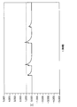
- the threshold value is set based on experimental values or experience values. Furthermore, it has an automatic threshold value adjustment function that uses a value obtained by adding an added value to the maximum value from the past maximum value record in the specified range, and it is possible to select which threshold value to use. A case where a signal component exceeding the selected threshold is detected is determined as “abnormal”. In the example of FIG. 3, 1.000 V is set as the threshold value. When the polishing apparatus is stably and steadily operated, the noise resistance design of the detection circuit, the signal amplification factor, and the like are set so that the noise level is 0.1 V or less.
- the present invention when a minute crack such as a crack or a chip occurs in the glass plate being polished, it is meaningful to detect it instantaneously and stop the polishing apparatus once. In the conventional method, the time spent for cleaning the polishing head and the polishing pad cannot be ignored. However, according to the present invention, since the glass plate is not crushed, the time spent for the cleaning work is short, and it is sufficient to be within several tens of minutes. Therefore, the interruption time of the polishing apparatus in the production process can be greatly shortened. In the present invention, for example, as shown in FIG.
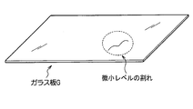
- a microcrack or the like is a short part of a large mother glass substrate that is cracked within several centimeters to several tens of centimeters or penetrates the front and back of a glass plate. It refers to a state where a small number of cracks have occurred.
- an AE sensor is attached to a plate that holds the polishing pad on a polishing surface plate.
- the AE sensor can accurately detect the elastic wave generated during polishing.
- the polishing apparatus uses water or slurry as the polishing liquid, the metal part other than the insulated detection surface of the AE sensor is physically contacted with the plate held on the polishing surface plate or via water or slurry. If they are brought into electrical contact, electrical noise may enter the AE sensor, and an abnormal signal at a minute level may not be discriminated. Therefore, it is preferable to attach a resin (insulating) cover for waterproofing and insulation to the AE sensor.
- the detection surface of the AE sensor is not attached to the plate as it is, but is attached to the plate through a metal cover that is in contact with the detection surface of the AE sensor and covers substantially the whole from the viewpoint of waterproofing.
- a biasing means such as a spring that presses the detection surface of the AE sensor against the metal cover from the viewpoint of increasing the detection accuracy of occurrence of a minute level abnormality.
- the polishing apparatus for the glass plate after detecting the breakage of the glass plate by the abnormality detection unit.
- the flowchart is shown in FIG. That is, the glass plate crack detection device is set up (S1), the processing of the glass plate is started (S2), and when the fine crack of the glass plate is detected, the polishing device is stopped (S3) and the polishing part is checked. Perform (S4) and restore the polishing apparatus (S5).
- a control unit that performs overall control of the entire polishing apparatus may be configured to stop the polishing apparatus. This eliminates the need for human work such as monitoring of the polishing apparatus by the monitor. Moreover, since the influence on another glass plate can be prevented in the case of continuous grinding
- the AE sensor detects an elastic wave from a glass plate from a polishing liquid that has permeated the polishing pad via the plate.
- the polishing liquid it is preferable to use a slurry containing cerium oxide or silica when polishing a glass plate and to use water when truing a polishing pad.
- the polishing pad is usually made of urethane, and urethane itself is difficult to transmit elastic waves.
- the polishing liquid penetrates into the urethane polishing pad, the elastic wave from the glass plate is passed through the plate from this polishing liquid. Is reliably detected by the AE sensor.
- the means for supplying the polishing liquid a means for forming a large number of polishing liquid supply holes in the polishing surface plate and the plate and supplying the polishing liquid from these polishing liquid supply holes to the polishing pad is preferable. Thereby, water or slurry can be uniformly supplied to the whole polishing pad.
- the AE sensor is preferably formed on the plate and attached to the lower surface of the protruding piece of the plate that protrudes laterally from the polishing surface plate.
- the rotating polishing head can be prevented from colliding with the AE sensor.
- a through hole may be formed in the central portion of the polishing surface plate, and the detection surface of the AE sensor may be attached to the plate through the through hole. If the AE sensor is attached to the central portion of the polishing surface plate in this manner, the distance between the glass plate cracking position and the AE sensor is often shortened, so that the detection sensitivity of the elastic wave is improved. What is necessary is just to determine suitably the number of AE sensors to attach according to the magnitude
- the attachment positions of the AE sensors are preferably arranged substantially evenly with respect to the glass plate in order to improve detection sensitivity.
- the frequency band output from the AE sensor to the abnormality detection unit is set in a range of 100 to 200 kHz by a filter.
- Various devices such as a glass plate cutting device, a chamfering device, a conveying device, and a secondary polishing device are installed around the glass plate polishing device. It is necessary to eliminate elastic waves with frequencies below 100 kHz due to mechanical vibrations from these devices. In addition, it is necessary to eliminate elastic waves having a frequency exceeding 200 kHz due to electrical noise.
- the lower limit value of the frequency band output from the AE sensor to the abnormality detection unit is 100 kHz, it is possible to prevent erroneous detection due to the elastic wave of the mechanical vibration, and the upper limit value is 200 kHz. Therefore, it is possible to prevent erroneous detection due to the elastic wave of the electrical noise.
- the upper limit value is 200 kHz. Therefore, it is possible to prevent erroneous detection due to the elastic wave of the electrical noise.
- a filter may be incorporated in the AE sensor itself, an output from the AE sensor may be output to the abnormality detection unit via the filter.
- a discriminator is preferably used as the filter.
- the initial stage of occurrence of abnormality such as cracking of the workpiece being polished is detected by the AE sensor, so that the interruption time caused by damage to the polishing tool, the workpiece, cleaning, etc. Can be minimized.
- the continuous operation in the polishing process can be improved, and the efficiency of the production plant can be improved. Further, since occurrence of a minute level of abnormality can be detected at an early stage, damage to the polishing apparatus and the polishing pad can be prevented, and maintenance of the apparatus can be facilitated.
- FIG. 1 is a perspective view of a polishing apparatus of the present invention.
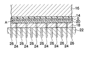
- FIG. 2 is an enlarged cross-sectional view of a main part of the polishing apparatus of FIG.
- FIG. 3 is a waveform diagram showing an output waveform from the AE sensor and a threshold value.
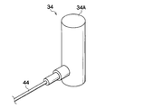
- FIG. 4 is an enlarged perspective view of the AE sensor.
- 5A is a perspective view of an AE sensor covered with a resin cover
- FIG. 5B is a perspective view of the metal cover as viewed from below
- FIG. 5C is a view of the metal cover. It is the perspective view seen from the upper part.
- FIG. 6 is a partial cross-sectional view of the polishing apparatus showing another attachment position of the AE sensor.
- FIG. 7 is a flowchart of the glass plate manufacturing method of the present invention.
- FIG. 8 is a top view showing a micro-level crack in the glass plate.
- FIG. 1 shows a perspective view of a polishing apparatus 10 according to an embodiment.
- FIG. 2 is an enlarged cross-sectional view showing the main structure of the polishing apparatus 10.
- This polishing apparatus 10 is a glass plate G manufactured in a rectangular shape (for example, polishing manufactured by a float method made of an alkali-free glass material for FPD use with a side of 2000 ⁇ 2200 mm to 2200 ⁇ 2600 mm, a thickness of 0.7 mm) It is a polishing apparatus that polishes the front glass plate (for example, AN100) ⁇ to the flatness required for the glass plate for liquid crystal display.
- the structure includes a polishing head 16 that holds a glass plate G on its lower surface via a sheet-like holding member 14, and a polishing surface plate 22 that holds a polishing pad 20 on its upper surface via an aluminum plate 18. It is configured.
- the glass plate G is held by a holding member 14 made of a self-adsorbing backing material or the like, and the polished surface A is pressed against the polishing pad 20 by the polishing head 16 so that the polished surface A is required to be flat. Polished every time.
- a slurry such as a cerium oxide aqueous solution
- the polishing liquid supply holes 24, 24... Are formed densely and uniformly in the polishing surface plate 22 and the plate 18.
- the slurry is uniformly supplied to the polishing pad 20.
- the polishing pad 20 for example, a foamed polyurethane type or a suede type is used, and is adhered to the plate 18.
- the polishing pad 20 may be one in relation to the glass plate G that is the object to be polished, but since the size of the polishing pad 20 is large corresponding to the size of the glass plate G, a plurality of divided polishings are performed. A single polishing pad 20 may be formed by combining the pads.
- suction holes 26, 26... are formed through the polishing surface plate 22, and these suction holes 26, 26... Are connected to a suction pump (not shown) via a valve. Therefore, by opening the valve, the suction force of the suction pump is transmitted to the suction holes 26, 26..., So that the plate 18 is adsorbed and held on the upper surface of the polishing surface plate 22. In addition, since the suction force of the suction pump is released by closing the valve, the polishing pad 20 can be removed from the polishing surface plate 22 together with the plate 18 when the state of the polishing pad 20 is checked or replaced.
- a spindle 28 is fixed to the upper center of the polishing head 16, and a rotation / lifting device 30 is connected to the spindle 28.
- the rotation / lifting device 30 is controlled by a control unit 32 that performs overall control of the entire polishing device 10, and the rotation speed and lowering operation (pressing force) suitable for polishing the glass plate G are controlled.
- the polishing apparatus 10 includes an AE (acoustic emission) sensor 34, an abnormality detection unit 36, and an alarm (warning means) 38.
- the AE sensor 34 one having a resonance frequency of 140 to 150 kHz is used in order to satisfactorily detect a crack in the initial stage of the glass plate G.
- the resonance frequency is preferably set near the center of the frequency band to be detected.
- the AE sensor 34 is attached to the plate 18.
- the abnormality detection unit 36 is a glass plate that is being polished based on an output signal from the AE sensor 34 when an elastic wave from the glass plate G that is being polished passes through the slurry and is detected by the AE sensor 34.
- the crack of the initial stage of G is detected.
- the alarm 38 is controlled by the control unit 32 so as to issue a warning when the abnormality detection unit 36 detects an initial crack of the glass sheet G.
- a signal indicating an elastic wave detected by the AE sensor 34 is amplified by a predetermined amount by the preamplifier 40, and only a signal in a predetermined frequency band is extracted by a discriminator 42, which will be described later. It is transmitted to the anomaly detection unit 36 using a high-speed communication method such as Line Communication).
- the abnormality detection unit 36 is composed of a recording medium such as a CD-ROM in which an algorithm for determining an initial crack of the glass sheet G that occurs during polishing is incorporated. Further, the cable 44 that transmits a signal to the PLC is routed around a place that is likely to be a noise source such as an inverter motor or a power line.
- the elastic wave generated during the polishing of the glass plate G by the polishing apparatus 10 passes through the slurry and is always detected by the AE sensor 34, and the information is always output to the abnormality detection unit 36.
- the anomaly detection unit 36 a threshold value that allows the occurrence of micro-cracks or chips such as cracks in the glass plate G is set in advance.
- FIG. 3 shows an output signal from the AE sensor 34 indicating the threshold value (1 V).
- the abnormality detection unit 36 detects that an abnormality such as a microcrack or a crack such as a crack has occurred in the glass plate G.
- the alarm 38 then issues a warning.
- the polishing unit 10 is automatically stopped immediately by the control unit 32.
- the initial stage of the occurrence of cracking of the glass plate G can be detected by the AE sensor 34, and the polishing apparatus 10 is automatically stopped immediately at that time.
- the crack of the glass plate G can be detected before the glass plate G is shattered. Therefore, according to this polishing apparatus 10, the interruption time resulting from the check of the polishing pad 20, the cleaning operation, the replacement operation, and the like can be minimized.
- the AE sensor 34 also detects low-level elastic waves generated during normal polishing of the glass plate G, but it is determined that even such elastic waves are detected as cracks. There is a risk of disturbing the polishing process. Therefore, in the polishing apparatus 10 according to the embodiment, the threshold value (1 V) based on an experimental value or an empirical value or a value calculated by an automatic threshold adjustment function is set as the threshold value.
- the AE sensor 34 is attached to the plate 18 that holds the polishing pad 20 on the polishing surface plate 22. Thereby, the AE sensor 34 can accurately detect the elastic wave generated during polishing.
- the polishing apparatus 10 uses a slurry when polishing the glass plate G, there is a possibility that electrical noise is generated due to conduction between the plate 18 and the AE sensor 34 excluding the AE sensor detection surface 34A.
- a resin cover 46 for waterproofing and insulation shown in FIG. 5A to the AE sensor 34 shown in FIG.
- the cover 46 covers a portion excluding the detection surface 34A of the AE sensor 34.
- the detection surface 34A of the AE sensor 34 is not directly attached to the plate 18, but is detected by the AE sensor 34 from the viewpoint of waterproofing and prevention of electrical continuity due to slurry as shown in FIGS. 5 (B) and 5 (C).
- a metal cover 48 that is in contact with the surface 34A and covers substantially the entire surface.
- an urging means such as a spring for pressing the detection surface 34A of the AE sensor 34 against the cover 48 from the viewpoint of increasing detection accuracy.
- FIG. 5B is a perspective view of the cover 48 viewed from below
- FIG. 5C is a perspective view of the cover 48 viewed from above. is there.
- the cover 48 is a box having an open bottom, and the detection surface 34A of the AE sensor 34 is pressed and fixed to the center of the lower surface of the top plate 48A via the urging means.
- nuts 48C and 48C are formed on both sides of the top plate 48A with the attachment portion 48B of the AE sensor 34 interposed therebetween. Then, through holes (not shown) are formed in the plate 18 so as to correspond to the nut parts 48C, 48C, and bolts (not shown) are passed through these through holes and fastened to the nut parts 48C, 48C. A cover 48 is fixed to the plate 18.
- system of the polishing apparatus is configured such that when the warning is issued from the alarm 38 in FIG. 1, the control unit 32 that performs overall control of the entire polishing apparatus 10 stops the polishing apparatus 10.
- the controller 32 controls the rotation / lifting device 30 so that the glass plate G is lifted (retracted) from the polishing pad 20 together with the polishing head 16 when the polishing device 10 is stopped. This makes it possible to easily take out the glass plate G at the initial stage of crack generation from the polishing head 16.
- the AE sensor 34 detects the elastic wave from the glass plate G from the slurry that has penetrated the polishing pad 20 through the plate 18.
- FIG. 6 shows the principle of detecting a crack in the glass plate G.
- the polishing pad 20 is usually made of urethane, and the urethane itself hardly transmits an elastic wave, but the slurry penetrates into the polishing pad 20 made of urethane. Therefore, the elastic wave from the point P is reliably detected by the AE sensor 34 from the slurry via the plate 18.
- the AE sensor 34 is formed on the plate 18 as shown in FIG. 1 and attached to the lower surface of the protruding piece 18A that protrudes laterally from the polishing surface plate 22.
- the AE sensor 34 is attached to the lower surface of the protruding piece 18A of the plate 18 projecting laterally from the polishing surface plate 22 in this way, the rotating polishing head 16 can be prevented from colliding with the AE sensor 34.
- FIG. 1 illustrates the case where the number of AE sensors is one, as described above, the number of AE sensors to be attached is preferably determined as appropriate according to the size of the glass plate.
- a through hole 22A is formed in the central portion of the polishing surface plate 22, and the detection surface of the AE sensor 34 indicated by a two-dot chain line through the through hole 22A. 34A may be attached to the lower surface of the plate 18. If the AE sensor 34 is attached to the central portion of the polishing surface plate 22 in this way, the distance between the break position of the glass plate G and the AE sensor 34 can be shortened. By taking such an arrangement, the detection sensitivity of the elastic wave is improved.
- the frequency band output from the AE sensor 34 to the abnormality detection unit 36 is set in the range of 100 to 200 kHz by the discriminator (filter) 42.
- Various devices such as a glass plate G cutting device, a chamfering device, and a drilling device are installed around the polishing device 10, and an elastic wave having a frequency (less than 100 kHz) caused by mechanical vibration from these devices.
- an elastic wave having a frequency (less than 100 kHz) caused by mechanical vibration from these devices.
- the polishing apparatus 10 since the lower limit value of the frequency band output from the AE sensor 34 to the abnormality detection unit 36 is 100 kHz, it is possible to prevent erroneous detection due to the elastic wave of the mechanical vibration. Further, since the upper limit value is set to 200 kHz, it is possible to prevent erroneous detection due to the elastic wave of the electrical noise. Note that the higher the upper limit value, the less the output of the AE sensor 34 is attenuated. Further, the AE sensor itself may incorporate a filter for extracting the frequency in the frequency band.
- the present invention is not limited to the above-described embodiments, and can be applied to substrate processing of electronic devices other than FPD, for example, glass substrates for optical elements, glass disks, solar cells and the like.
- the polishing pad 20 is illustrated as the polishing tool, and the glass plate G is illustrated as the object to be polished.
- the polishing tool is a truing grindstone (planar electrodeposition diamond).
- the present invention can also be applied to an apparatus for truing the polishing pad 20 with a truing grindstone using a polishing plate as a plate) and an object to be polished as the polishing pad 20. Since the configuration of this apparatus replaces the glass plate G with a truing grindstone in FIG. 2, the illustration is omitted here.
- the polishing pad 20 when the polishing pad 20 is trued, water is used as a polishing liquid, and an elastic wave generated from the polishing pad 20 during truing passes through the water and is detected by the AE sensor 34.
- Information from the AE sensor 34 is always output to the abnormality detection unit 36, and the abnormality detection unit 36 is preset with a threshold value of the appropriate truing efficiency lower limit of the polishing pad 20.
- the alarm 38 issues a warning.
Landscapes
- Engineering & Computer Science (AREA)
- Mechanical Engineering (AREA)
- Constituent Portions Of Griding Lathes, Driving, Sensing And Control (AREA)
- Finish Polishing, Edge Sharpening, And Grinding By Specific Grinding Devices (AREA)
- Grinding Of Cylindrical And Plane Surfaces (AREA)
Abstract
Description
取り付けるAEセンサの数は、ガラス板の大きさに応じて適宜決めればよい。例えば、一辺が3000mm×3000mm以上のガラス板に対しては2つ以上のAEセンサを取り付けることが好ましい。
AEセンサを複数取り付ける場合のAEセンサの取付位置は、検出感度を向上させるため、ガラス板に対してほぼ均等に配置されることが好ましい。例えば、2つのAEセンサを取り付ける場合は、ガラス板を挟んでAEセンサが対称となるように取り付けることが好ましい。
図1では、AEセンサの数がひとつの場合を図示しているが、前述の通り、取り付けるAEセンサの数はガラス板の大きさに応じて適宜決定することが好ましい。
本出願は、2008年12月12日出願の日本特許出願2008-317269に基づくものであり、その内容はここに参照として取り込まれる。
14 保持部材
16 研磨ヘッド
18 プレート
20 研磨パッド
22 研磨定盤
22A 貫通孔
24 研磨液供給孔
26 吸引孔
28 スピンドル
30 回転/昇降装置
32 制御部
34 AEセンサ
34A 検出面
36 異常検知部
38 アラーム
40 プリアンプ
42 ディスクリミネータ
44 PLCケーブル
46 カバー
48 カバー
48A 天板
48B 取付部
48C ナット部
Claims (17)
- 研磨具と被研磨物とを相対的に押し付けて移動させるとともに、研磨具と被研磨物との間に研磨液を供給しながら研磨具によって被研磨物を研磨する研磨装置であって、
研磨具又は被研磨物を支持するプレートに取り付けられたAEセンサと、
被研磨物からの弾性波が前記AEセンサに検出された際のAEセンサからの出力信号に基づいて研磨中の異常を検知する異常検知部と、
前記異常検知部によって被研磨物の異常が検知されると警告を発する警告手段、を備えていることを特徴とする研磨装置。 - 前記研磨具が研磨パッドであり、前記被研磨物がガラス板である請求項1に記載の研磨装置。
- 前記研磨具がツルーイング砥石であり、前記被研磨物が研磨パッドである請求項1に記載の研磨装置。
- 前記異常検知部によって前記ガラス板の異常が検知されると、前記研磨装置を制御する制御部によって研磨装置が停止される請求項2に記載の研磨装置。
- 前記AEセンサが、前記ガラス板からの弾性波を、前記研磨パッドに浸透した前記研磨液から前記プレートを介して検出する請求項2又は4に記載の研磨装置。
- 前記研磨パッドが、前記プレートを介して研磨定盤により保持され、
前記AEセンサが、前記プレートに形成されるとともに前記研磨定盤から側方に張り出された突出片の下面に取り付けられている請求項2、4、又は5のいずれか1項に記載の研磨装置。 - 前記AEセンサから前記異常検知部に出力される周波数帯域が、フィルタによって100~200kHzの範囲に設定されている請求項2、4、5又は6のいずれか1項に記載の研磨装置。
- 前記被研磨物からの弾性波が、前記研磨液を通過して前記AEセンサに検出される請求項1~7のうちいずれか1項に記載の研磨装置。
- 研磨具と被研磨物とを相対的に押し付けて移動させるとともに、研磨具と被研磨物との間に研磨液を供給しながら研磨具によって被研磨物を研磨する研磨方法であって、
研磨具又は被研磨物を支持するプレートにAEセンサが取り付けられ、
被研磨物からの弾性波が前記AEセンサに検出された際のAEセンサからの出力信号に基づいて異常検知部が研磨中の異常を検知し、
前記異常検知部によって被研磨物の異常が検知されると警告手段が警告を発することを特徴とする研磨方法。 - 前記研磨具が研磨パッドであり、前記被研磨物がガラス板である請求項9に記載の研磨方法。
- 前記研磨具がツルーイング砥石であり、前記被研磨物が研磨パッドである請求項9に記載の研磨方法。
- 前記異常検知部によって前記ガラス板の異常が検知されると、前記研磨装置を制御部によって制御し、研磨装置を停止させる請求項10に記載の研磨方法。
- 前記AEセンサが、前記ガラス板からの弾性波を、前記研磨パッドに浸透した前記研磨液から前記プレートを介して検出する請求項10又は12に記載の研磨方法。
- 前記研磨パッドが、前記プレートを介して研磨定盤により保持され、
前記AEセンサが、前記プレートに形成されるとともに前記研磨定盤から側方に張り出された突出片の下面に取り付けられている請求項10、12、又は13のいずれか1項に記載の研磨方法。 - 前記AEセンサから前記異常検知部に出力される周波数帯域が、フィルタによって100~200kHzの範囲に設定されている請求項10、12、13又は14のいずれか1項に記載の研磨方法。
- 前記被研磨物からの弾性波が、前記研磨液を通過して前記AEセンサに検出される請求項9~15のうちいずれか1項に記載の研磨方法。
- 請求項9、10、12~16のいずれか1項に記載の研磨方法を用いて、ガラス板の加工を行うことを特徴とするガラス板の製造方法。
Priority Applications (2)
| Application Number | Priority Date | Filing Date | Title |
|---|---|---|---|
| JP2010542083A JP5533666B2 (ja) | 2008-12-12 | 2009-12-01 | 研磨装置、及び研磨方法、並びにガラス板の製造方法 |
| CN200980149953.1A CN102245350B (zh) | 2008-12-12 | 2009-12-01 | 研磨装置及研磨方法、以及玻璃板的制造方法 |
Applications Claiming Priority (2)
| Application Number | Priority Date | Filing Date | Title |
|---|---|---|---|
| JP2008-317269 | 2008-12-12 | ||
| JP2008317269 | 2008-12-12 |
Publications (1)
| Publication Number | Publication Date |
|---|---|
| WO2010067732A1 true WO2010067732A1 (ja) | 2010-06-17 |
Family
ID=42242720
Family Applications (1)
| Application Number | Title | Priority Date | Filing Date |
|---|---|---|---|
| PCT/JP2009/070156 Ceased WO2010067732A1 (ja) | 2008-12-12 | 2009-12-01 | 研磨装置、及び研磨方法、並びにガラス板の製造方法 |
Country Status (5)
| Country | Link |
|---|---|
| JP (1) | JP5533666B2 (ja) |
| KR (1) | KR101601346B1 (ja) |
| CN (1) | CN102245350B (ja) |
| TW (1) | TW201029808A (ja) |
| WO (1) | WO2010067732A1 (ja) |
Cited By (9)
| Publication number | Priority date | Publication date | Assignee | Title |
|---|---|---|---|---|
| CN102225534A (zh) * | 2011-04-19 | 2011-10-26 | 清华大学 | 用于控制修整器的气动控制回路和修整设备 |
| CN102485424A (zh) * | 2010-12-03 | 2012-06-06 | 中芯国际集成电路制造(北京)有限公司 | 抛光装置及其异常处理方法 |
| CN106938411A (zh) * | 2017-04-20 | 2017-07-11 | 上海理工大学 | 外圆磨削加工时间在线优化方法 |
| JP2017190971A (ja) * | 2016-04-12 | 2017-10-19 | 旭硝子株式会社 | ガラス割れ検知方法、ガラス割れ検知装置、ガラス板の研磨方法、ガラス板の研磨装置、及びガラス板の製造方法 |
| US9878934B2 (en) | 2013-05-03 | 2018-01-30 | Corning Incorporated | Methods and apparatus for conveying a glass ribbon |
| CN111941282A (zh) * | 2019-05-17 | 2020-11-17 | Agc株式会社 | 异常检测装置以及异常检测方法 |
| WO2022014475A1 (ja) * | 2020-07-13 | 2022-01-20 | 株式会社荏原製作所 | 基板処理装置及び音響センサ用防水装置 |
| KR20240023190A (ko) * | 2021-07-06 | 2024-02-20 | 어플라이드 머티어리얼스, 인코포레이티드 | 화학적 기계적 연마를 위한 음향 센서의 결합 |
| CN119304715A (zh) * | 2024-12-18 | 2025-01-14 | 杭州泓芯微半导体有限公司 | 石英件全自动研磨装置 |
Families Citing this family (8)
| Publication number | Priority date | Publication date | Assignee | Title |
|---|---|---|---|---|
| US20140329439A1 (en) * | 2013-05-01 | 2014-11-06 | Applied Materials, Inc. | Apparatus and methods for acoustical monitoring and control of through-silicon-via reveal processing |
| CN103639883A (zh) * | 2013-11-25 | 2014-03-19 | 银川博聚工业产品设计有限公司 | 轴承金相分析研磨机 |
| US10478937B2 (en) | 2015-03-05 | 2019-11-19 | Applied Materials, Inc. | Acoustic emission monitoring and endpoint for chemical mechanical polishing |
| JP6846657B2 (ja) * | 2017-01-20 | 2021-03-24 | 株式会社ディスコ | 切削装置 |
| KR102677387B1 (ko) | 2018-03-13 | 2024-06-24 | 어플라이드 머티어리얼스, 인코포레이티드 | 화학적 기계적 연마 동안 진동들의 모니터링 |
| JP2020015105A (ja) * | 2018-07-23 | 2020-01-30 | 東京エレクトロン株式会社 | 基板処理装置および基板処理方法 |
| JP7711466B2 (ja) * | 2021-07-14 | 2025-07-23 | Agc株式会社 | 異常検知装置、異常検知方法及びガラス板の生産方法 |
| JP7659490B2 (ja) * | 2021-12-22 | 2025-04-09 | 株式会社荏原製作所 | 音響センサの較正方法 |
Citations (3)
| Publication number | Priority date | Publication date | Assignee | Title |
|---|---|---|---|---|
| JP2004098250A (ja) * | 2002-09-11 | 2004-04-02 | Sumitomo Heavy Ind Ltd | 両頭研削装置 |
| JP2005022028A (ja) * | 2003-07-02 | 2005-01-27 | Tokyo Seimitsu Co Ltd | 研磨パッドのドレッシング装置及び該装置を有する加工装置 |
| JP2008155299A (ja) * | 2006-12-21 | 2008-07-10 | Sharp Corp | 液晶パネル基板の研削装置 |
Family Cites Families (5)
| Publication number | Priority date | Publication date | Assignee | Title |
|---|---|---|---|---|
| CN2174291Y (zh) * | 1993-10-06 | 1994-08-17 | 王怀章 | 轴承内外环沟道车磨自动调整沟位装置 |
| CN1168127C (zh) * | 2000-09-22 | 2004-09-22 | 联华电子股份有限公司 | 化学机械研磨异常探测装置 |
| JP4328585B2 (ja) * | 2003-09-02 | 2009-09-09 | トーヨーエイテック株式会社 | 切線加工工具の劣化状態検知方法および切線加工装置 |
| JP4569749B2 (ja) | 2004-07-23 | 2010-10-27 | 旭硝子株式会社 | ガラス板の割れ検出方法及びその装置並びにガラス板の研磨方法及びその装置 |
| CN101200052A (zh) * | 2006-12-13 | 2008-06-18 | 上海华虹Nec电子有限公司 | 研磨垫打磨器 |
-
2009
- 2009-12-01 KR KR1020117013256A patent/KR101601346B1/ko not_active Expired - Fee Related
- 2009-12-01 CN CN200980149953.1A patent/CN102245350B/zh active Active
- 2009-12-01 WO PCT/JP2009/070156 patent/WO2010067732A1/ja not_active Ceased
- 2009-12-01 JP JP2010542083A patent/JP5533666B2/ja not_active Expired - Fee Related
- 2009-12-11 TW TW98142595A patent/TW201029808A/zh unknown
Patent Citations (3)
| Publication number | Priority date | Publication date | Assignee | Title |
|---|---|---|---|---|
| JP2004098250A (ja) * | 2002-09-11 | 2004-04-02 | Sumitomo Heavy Ind Ltd | 両頭研削装置 |
| JP2005022028A (ja) * | 2003-07-02 | 2005-01-27 | Tokyo Seimitsu Co Ltd | 研磨パッドのドレッシング装置及び該装置を有する加工装置 |
| JP2008155299A (ja) * | 2006-12-21 | 2008-07-10 | Sharp Corp | 液晶パネル基板の研削装置 |
Cited By (18)
| Publication number | Priority date | Publication date | Assignee | Title |
|---|---|---|---|---|
| CN102485424A (zh) * | 2010-12-03 | 2012-06-06 | 中芯国际集成电路制造(北京)有限公司 | 抛光装置及其异常处理方法 |
| CN102485424B (zh) * | 2010-12-03 | 2015-01-21 | 中芯国际集成电路制造(北京)有限公司 | 抛光装置及其异常处理方法 |
| CN102225534A (zh) * | 2011-04-19 | 2011-10-26 | 清华大学 | 用于控制修整器的气动控制回路和修整设备 |
| US9878934B2 (en) | 2013-05-03 | 2018-01-30 | Corning Incorporated | Methods and apparatus for conveying a glass ribbon |
| JP2017190971A (ja) * | 2016-04-12 | 2017-10-19 | 旭硝子株式会社 | ガラス割れ検知方法、ガラス割れ検知装置、ガラス板の研磨方法、ガラス板の研磨装置、及びガラス板の製造方法 |
| KR20170116955A (ko) | 2016-04-12 | 2017-10-20 | 아사히 가라스 가부시키가이샤 | 유리 깨짐 검지 방법, 유리 깨짐 검지 장치, 유리판의 연마 방법, 유리판의 연마 장치, 및 유리판의 제조 방법 |
| TWI721109B (zh) * | 2016-04-12 | 2021-03-11 | 日商Agc股份有限公司 | 玻璃破裂檢測方法、玻璃破裂檢測裝置、玻璃板之研磨方法、玻璃板之研磨裝置、以及玻璃板之製造方法 |
| CN106938411A (zh) * | 2017-04-20 | 2017-07-11 | 上海理工大学 | 外圆磨削加工时间在线优化方法 |
| KR20200132736A (ko) | 2019-05-17 | 2020-11-25 | 에이지씨 가부시키가이샤 | 이상 검지 장치 및 이상 검지 방법 |
| CN111941282A (zh) * | 2019-05-17 | 2020-11-17 | Agc株式会社 | 异常检测装置以及异常检测方法 |
| WO2022014475A1 (ja) * | 2020-07-13 | 2022-01-20 | 株式会社荏原製作所 | 基板処理装置及び音響センサ用防水装置 |
| JP2022017108A (ja) * | 2020-07-13 | 2022-01-25 | 株式会社荏原製作所 | 基板処理装置及び音響センサ用防水装置 |
| JP7523269B2 (ja) | 2020-07-13 | 2024-07-26 | 株式会社荏原製作所 | 基板処理装置及び音響センサ用防水装置 |
| KR20240023190A (ko) * | 2021-07-06 | 2024-02-20 | 어플라이드 머티어리얼스, 인코포레이티드 | 화학적 기계적 연마를 위한 음향 센서의 결합 |
| JP2024525537A (ja) * | 2021-07-06 | 2024-07-12 | アプライド マテリアルズ インコーポレイテッド | 化学機械研磨のための音響センサの結合 |
| KR102874149B1 (ko) | 2021-07-06 | 2025-10-22 | 어플라이드 머티어리얼스, 인코포레이티드 | 화학적 기계적 연마를 위한 음향 센서의 결합 |
| JP7815413B2 (ja) | 2021-07-06 | 2026-02-17 | アプライド マテリアルズ インコーポレイテッド | 化学機械研磨のための音響センサの結合 |
| CN119304715A (zh) * | 2024-12-18 | 2025-01-14 | 杭州泓芯微半导体有限公司 | 石英件全自动研磨装置 |
Also Published As
| Publication number | Publication date |
|---|---|
| CN102245350A (zh) | 2011-11-16 |
| CN102245350B (zh) | 2016-01-20 |
| JP5533666B2 (ja) | 2014-06-25 |
| JPWO2010067732A1 (ja) | 2012-05-17 |
| KR20110095308A (ko) | 2011-08-24 |
| TW201029808A (en) | 2010-08-16 |
| KR101601346B1 (ko) | 2016-03-08 |
Similar Documents
| Publication | Publication Date | Title |
|---|---|---|
| JP5533666B2 (ja) | 研磨装置、及び研磨方法、並びにガラス板の製造方法 | |
| CN107378750B (zh) | 玻璃破裂检测方法及检测装置、玻璃板的研磨方法及研磨装置、以及玻璃板的制造方法 | |
| US6997778B2 (en) | Polishing apparatus | |
| TWI686264B (zh) | 用於聲學監控及控制直通矽穿孔之顯露處理的設備及方法 | |
| KR20140098636A (ko) | 반도체 소자의 불량 검출장치 및 검출방법 | |
| US6488569B1 (en) | Method and apparatus for detecting micro-scratches in semiconductor wafers during polishing process | |
| US7163435B2 (en) | Real time monitoring of CMP pad conditioning process | |
| JP2018167367A (ja) | 研削装置 | |
| CN110757336A (zh) | 基板处理装置和基板处理方法 | |
| TWI831973B (zh) | 異常檢測裝置及異常檢測方法 | |
| CN102445494A (zh) | 玻璃板的破裂检测方法及其装置以及研磨方法及其装置 | |
| EP4355699B1 (en) | Installation for producing at least one useful part from a glass pane | |
| JP3227876U (ja) | ガラス板の切断面検査装置 | |
| JP2014172161A (ja) | 基板割れ検知装置およびこれを備えた研磨装置並びに基板割れ検知方法 | |
| KR100856361B1 (ko) | 유리판의 균열 검출 방법 및 그 장치 그리고 유리판의 연마방법 및 그 장치 | |
| JP2016046437A (ja) | 粘着テープ剥離方法および粘着テープ剥離装置 | |
| CN108188931A (zh) | 双面行星磨削/研磨加工中工件破碎的在线控制系统 | |
| JP7711466B2 (ja) | 異常検知装置、異常検知方法及びガラス板の生産方法 | |
| JPH11183447A (ja) | 被加工材の割れ発生予知方法及びこれを利用したウエハの加工方法並びに研削盤 | |
| US20140287659A1 (en) | Machining method and machining device of component | |
| JPH11254304A (ja) | センサを組み込んだ定盤 | |
| JPH11198034A (ja) | 研削加工方法及び研削盤 | |
| JP2005057100A (ja) | 半導体基板の研磨方法及び研磨装置 | |
| KR20130062580A (ko) | 글라스 에지의 연삭장치 | |
| JP2000024919A (ja) | ウエハの加工方法及び研削盤 |
Legal Events
| Date | Code | Title | Description |
|---|---|---|---|
| WWE | Wipo information: entry into national phase |
Ref document number: 200980149953.1 Country of ref document: CN |
|
| 121 | Ep: the epo has been informed by wipo that ep was designated in this application |
Ref document number: 09831836 Country of ref document: EP Kind code of ref document: A1 |
|
| WWE | Wipo information: entry into national phase |
Ref document number: 2010542083 Country of ref document: JP |
|
| ENP | Entry into the national phase |
Ref document number: 20117013256 Country of ref document: KR Kind code of ref document: A |
|
| NENP | Non-entry into the national phase |
Ref country code: DE |
|
| 122 | Ep: pct application non-entry in european phase |
Ref document number: 09831836 Country of ref document: EP Kind code of ref document: A1 |