WO2010067680A1 - 車両用回転電機 - Google Patents
車両用回転電機 Download PDFInfo
- Publication number
- WO2010067680A1 WO2010067680A1 PCT/JP2009/069086 JP2009069086W WO2010067680A1 WO 2010067680 A1 WO2010067680 A1 WO 2010067680A1 JP 2009069086 W JP2009069086 W JP 2009069086W WO 2010067680 A1 WO2010067680 A1 WO 2010067680A1
- Authority
- WO
- WIPO (PCT)
- Prior art keywords
- rotating electrical
- electrical machine
- temperature sensor
- terminal block
- refrigerant
- Prior art date
- Legal status (The legal status is an assumption and is not a legal conclusion. Google has not performed a legal analysis and makes no representation as to the accuracy of the status listed.)
- Ceased
Links
Images



Classifications
-
- H—ELECTRICITY
- H02—GENERATION; CONVERSION OR DISTRIBUTION OF ELECTRIC POWER
- H02K—DYNAMO-ELECTRIC MACHINES
- H02K5/00—Casings; Enclosures; Supports
- H02K5/04—Casings or enclosures characterised by the shape, form or construction thereof
- H02K5/22—Auxiliary parts of casings not covered by groups H02K5/06-H02K5/20, e.g. shaped to form connection boxes or terminal boxes
- H02K5/225—Terminal boxes or connection arrangements
-
- H—ELECTRICITY
- H02—GENERATION; CONVERSION OR DISTRIBUTION OF ELECTRIC POWER
- H02K—DYNAMO-ELECTRIC MACHINES
- H02K11/00—Structural association of dynamo-electric machines with electric components or with devices for shielding, monitoring or protection
- H02K11/20—Structural association of dynamo-electric machines with electric components or with devices for shielding, monitoring or protection for measuring, monitoring, testing, protecting or switching
- H02K11/25—Devices for sensing temperature, or actuated thereby
-
- H—ELECTRICITY
- H02—GENERATION; CONVERSION OR DISTRIBUTION OF ELECTRIC POWER
- H02K—DYNAMO-ELECTRIC MACHINES
- H02K9/00—Arrangements for cooling or ventilating
-
- H—ELECTRICITY
- H02—GENERATION; CONVERSION OR DISTRIBUTION OF ELECTRIC POWER
- H02K—DYNAMO-ELECTRIC MACHINES
- H02K9/00—Arrangements for cooling or ventilating
- H02K9/19—Arrangements for cooling or ventilating for machines with closed casing and closed-circuit cooling using a liquid cooling medium, e.g. oil
-
- H—ELECTRICITY
- H02—GENERATION; CONVERSION OR DISTRIBUTION OF ELECTRIC POWER
- H02K—DYNAMO-ELECTRIC MACHINES
- H02K9/00—Arrangements for cooling or ventilating
- H02K9/19—Arrangements for cooling or ventilating for machines with closed casing and closed-circuit cooling using a liquid cooling medium, e.g. oil
- H02K9/193—Arrangements for cooling or ventilating for machines with closed casing and closed-circuit cooling using a liquid cooling medium, e.g. oil with provision for replenishing the cooling medium; with means for preventing leakage of the cooling medium
Definitions
- the present invention relates to a vehicular rotating electrical machine cooled by a refrigerant, and more particularly to a terminal block to which a temperature sensor for measuring the temperature of a coil end in the vehicular rotating electrical machine is attached.
- Rotating electrical machines such as motors and generators used in electric vehicles, hybrid vehicles, and the like generate coils due to iron loss and resistance. Therefore, the rotating electrical machines are provided with cooling means such as air cooling or refrigerant.
- cooling means such as air cooling or refrigerant.
- the rotating electrical machine generates heat due to long-term use or overload, and may overheat when cooling with the refrigerant is insufficient. For this reason, conventionally, the temperature of each part of the rotating electrical machine is measured, and when the measured temperature exceeds a predetermined temperature, control such as limiting the load on the rotating electrical machine or stopping the rotating electrical machine is performed.
- a three-phase AC type rotating electrical machine controlled by an inverter is often used. Since this rotating electrical machine is integrated with an engine and a gear mission and mounted on a vehicle, a cooling method is adopted in which oil as a refrigerant is circulated inside the rotating electrical machine.
- oil as a refrigerant is circulated inside the rotating electrical machine.
- Patent Document 1 discloses that the insulating layer on the outer surface of the neutral point fixed to the coil end of the vehicular rotating electric machine is protected to reduce the size of the vehicular rotating electric machine and at the same time accurately measure the coil temperature. Techniques for performing are disclosed.
- Patent Document 2 discloses a temperature sensor in which a position sensor of a temperature sensor fixed to a coil end is prevented from being displaced and a coil is molded with resin for the purpose of protecting the coil and inserted into a hole formed in the resin part.
- a rotating electric machine having the following is disclosed.
- the temperature sensor can be prevented from being misaligned by supporting the temperature sensor on the inner peripheral surface defined by the hole portion of the coil molded by resin, and the temperature measurement is not disturbed. Temperature measurement is possible.
- the temperature sensor inserted into the hole of the coil needs to be brought into close contact with the hole and filled with the adhesive, and the terminal block for fixing the U phase, V phase, and W phase extending from the coil Since it is necessary to attach separately, it has been desired to further reduce the number of parts and the number of mounting steps.
- the present invention relates to a terminal block for attaching a temperature sensor for measuring the temperature of a coil end to a rotating electrical machine for a vehicle, and provides a terminal block capable of suppressing temperature measurement disturbance and reducing the number of parts and the number of mounting steps. For the purpose.
- a rotating electrical machine for a vehicle includes a coil provided on a cylindrical stator and a resin-molded coil end in a rotating electrical machine for a vehicle cooled by a refrigerant.
- a temperature sensor for detecting the temperature a temperature sensor is housed in a hole formed in the coil end; and the temperature sensor is brought into contact with the coil end with a predetermined load; and a terminal block for connecting a terminal extending from the coil; It is characterized by having.
- the terminal block includes an inflow suppressing member that covers the temperature sensor from the outer circumferential direction of the coil end and suppresses the inflow of the refrigerant around the temperature sensor. .
- the terminal block is provided with a refrigerant pool and a refrigerant channel that passes from the refrigerant pool to the lower part of the terminal block, and the refrigerant channel provided inside the terminal block is used as the refrigerant. It is characterized by flowing.
- the refrigerant flow path is disposed at a predetermined distance from the temperature sensor so that the temperature sensor stably measures the temperature of the central portion of the coil end. It is characterized by that.
- the refrigerant pool of the terminal block is arranged above the refrigerant flow path, and the refrigerant flows down the refrigerant flow path due to gravity.
- FIG. 1 shows a configuration of a rotating electrical machine 100 for a vehicle incorporated in a vehicle transmission.
- the rotating electrical machine 100 is driven by a three-phase alternating current, and is provided in a stator core 13, a mold resin 12 covering a coil wound around the stator core 13, a rotor core 40, a shaft 11 provided in the rotor core 40, and a coil end portion.
- the terminal block 20 and the case 30 covering the rotating electrical machine 100 are provided.
- a plurality of power cables extending from the terminal block 20 are drawn out of the case 30 through a case terminal box 31.
- the temperature sensor 22 is fixed to the hole of the mold resin 12 by the terminal block 20, and the temperature sensor 22 measures the temperature near the heat generation source.
- FIG. 2 shows the structure of the A-A ′ cross section of the rotating electrical machine 100 shown in FIG.
- the rotor core 40 of the rotating electrical machine 100 has a shaft 11 at the center and a plurality of permanent magnets 41 arranged on the outer periphery.
- the stator core 13 is disposed outside the rotor core 40, and U-phase, V-phase, and W-phase coils 42 are wound around the stator core 13, and the coil ends are connected to corresponding electrodes of the terminal block 20.
- An oil discharge port 32 for cooling is provided on the upper side of the rotating electrical machine, and the coil end and the terminal block 20 are cooled by the oil transmitted along the outer periphery of the coil end, and the oil is collected in an oil reservoir 39 on the lower side of the rotating electrical machine. It is done.
- FIG. 3 shows the configuration of the terminal block 20 in the rotating electrical machine 100.
- coil terminals such as U-phase, V-phase, and W-phase are provided on the upstream side of the oil, and the temperature sensor 22 is disposed on the downstream side thereof.
- an oil inflow suppressing member (14, 15) is provided that seals the outer periphery of the temperature sensor 22 and suppresses the inflow of oil.
- the oil flow path 29 also contributes to cooling of the stator and realizes preset heat dissipation even in a portion where heat dissipation is limited by the terminal block 20.
- a pressing member 23 that is an elastic body such as a spring or rubber is provided between the temperature sensor 22 and the base 21 of the terminal block 20, and the temperature sensor 22.
- a seal 27 is provided to prevent oil from entering the cable.
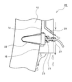
- FIG. 4 shows the temperature sensor mounting structure of the terminal block 20 and the oil flow.
- One of the characteristic features of the present invention is that not only the surface of the terminal block 20 but also the oil reservoir 28 shown in FIG. This is because the inside of the terminal block 20 is cooled by adopting a structure in which the flow is made to flow.
- the oil flows around the terminal block 20, and the oil collected in the oil reservoir 28 of FIG. 1 flows through the oil flow path 29 by gravity. Furthermore, since the terminal block 20 has a plurality of oil flow paths 29, not only the surface of the terminal block 20 but also the mold resin 12 covered with the terminal block 20 can be cooled. Note that the temperature sensor 22 can optimize the shape of the terminal block 20 and the oil flow path 29 so that the temperature measurement 22 is not disturbed by a change in cooling due to oil, so that the maximum temperature can be accurately measured. In addition, it is possible to reduce the man-hours for attaching the temperature sensor 22.
- FIGS. 5A to 5C show temperature sensor mounting structures according to other embodiments.
- FIG. 5A shows a configuration in which the temperature sensor 22 is pressed against the mold resin 12 by a spring 51 with little change in pressing force due to temperature change.
- FIG. 5B although the pressing force slightly changes depending on the temperature change, it can be integrated with the terminal block 20 by the flange shape provided at the bottom of the elastic body 52 and the concave portion holding the temperature sensor 22. It is possible to reduce the installation man-hours.
- FIG. 5C shows a configuration in which the temperature sensor 22 is held on the terminal block 20 by a large O-ring 53 so that a pressing force can be obtained.
- the temperature sensor for measuring the temperature of the coil end is pressed against the mold resin with an appropriate load and held, and the cooling around the temperature sensor is kept constant.
- a terminal block capable of suppressing the measurement disturbance of the temperature sensor and reducing the number of parts and the number of mounting steps.
Landscapes
- Engineering & Computer Science (AREA)
- Power Engineering (AREA)
- Microelectronics & Electronic Packaging (AREA)
- Motor Or Generator Frames (AREA)
Abstract
Description
Claims (5)
- 冷媒によって冷却される車両用回転電機において、
円筒状のステータに設けられたコイルと、
樹脂モールドされたコイルエンドの温度を検出する温度センサと、
コイルエンドに形成された穴部に温度センサが収容され、温度センサをコイルエンドに予め決められた荷重で接触させると共に、コイルから伸びる端子を接続する端子台と、
を有することを特徴とする車両用回転電機。 - 請求項1に記載の車両用回転電機において、
端子台は、
コイルエンドの円周方向外側より温度センサを覆うと共に、温度センサ周囲に冷媒の流入を抑制する流入抑制部材を有することを特徴とする車両用回転電機。 - 請求項2に記載の車両用回転電機において、
端子台には冷媒溜まりと、冷媒溜まりから端子台下部に抜ける冷媒流路と、が設けられ、端子台の内部に設けられた冷媒流路を冷媒が流れることを特徴とする車両用回転電機。 - 請求項2に記載の車両用回転電機において、
冷媒流路は、温度センサがコイルエンドの中心部位の温度を安定して測定するために温度センサから予め決められた距離だけ離間して配置されたことを特徴とする車両用回転電機。 - 請求項3に記載の車両用回転電機において、
端子台の冷媒溜まりは、冷媒流路の上側に配置され、冷媒が重力により冷媒流路を流れ落ちることを特徴とする車両用回転電機。
Priority Applications (3)
| Application Number | Priority Date | Filing Date | Title |
|---|---|---|---|
| CN2009801485967A CN102239624B (zh) | 2008-12-09 | 2009-11-10 | 车辆用旋转电机 |
| DE112009003698T DE112009003698T5 (de) | 2008-12-09 | 2009-11-10 | Motorgenerator für ein fahrzeug |
| US13/133,522 US8803378B2 (en) | 2008-12-09 | 2009-11-10 | Motor generator for vehicle technical field |
Applications Claiming Priority (2)
| Application Number | Priority Date | Filing Date | Title |
|---|---|---|---|
| JP2008313491A JP4535189B2 (ja) | 2008-12-09 | 2008-12-09 | 車両用回転電機 |
| JP2008-313491 | 2008-12-09 |
Publications (1)
| Publication Number | Publication Date |
|---|---|
| WO2010067680A1 true WO2010067680A1 (ja) | 2010-06-17 |
Family
ID=42242672
Family Applications (1)
| Application Number | Title | Priority Date | Filing Date |
|---|---|---|---|
| PCT/JP2009/069086 Ceased WO2010067680A1 (ja) | 2008-12-09 | 2009-11-10 | 車両用回転電機 |
Country Status (5)
| Country | Link |
|---|---|
| US (1) | US8803378B2 (ja) |
| JP (1) | JP4535189B2 (ja) |
| CN (1) | CN102239624B (ja) |
| DE (1) | DE112009003698T5 (ja) |
| WO (1) | WO2010067680A1 (ja) |
Cited By (5)
| Publication number | Priority date | Publication date | Assignee | Title |
|---|---|---|---|---|
| CN102570701A (zh) * | 2012-02-29 | 2012-07-11 | 重庆长安汽车股份有限公司 | 纯电动汽车、动力系统及驱动电机的接线装置 |
| CN103391858A (zh) * | 2011-02-18 | 2013-11-13 | Ntn株式会社 | 轮毂电机驱动装置 |
| DE102013201835A1 (de) | 2013-02-05 | 2014-08-21 | Zf Friedrichshafen Ag | Anordnung zur Temperaturerfassung einer Statorwicklung einer elektrischen Maschine |
| JP2018174604A (ja) * | 2017-03-31 | 2018-11-08 | 日立オートモティブシステムズ株式会社 | 回転電機及びそれに用いられる固定子 |
| JP2018183009A (ja) * | 2017-04-21 | 2018-11-15 | 三菱電機株式会社 | 回転電機 |
Families Citing this family (39)
| Publication number | Priority date | Publication date | Assignee | Title |
|---|---|---|---|---|
| JP4535189B2 (ja) * | 2008-12-09 | 2010-09-01 | トヨタ自動車株式会社 | 車両用回転電機 |
| JP5811665B2 (ja) * | 2011-07-28 | 2015-11-11 | トヨタ自動車株式会社 | 回転電気 |
| CN103959610B (zh) * | 2011-09-14 | 2015-11-25 | 丰田自动车株式会社 | 旋转电机 |
| JP2013074711A (ja) * | 2011-09-27 | 2013-04-22 | Toyota Motor Corp | 電動機装置 |
| US9136739B2 (en) * | 2011-11-22 | 2015-09-15 | Honda Motor Co., Ltd. | Rotary electric machine |
| SE536235C2 (sv) * | 2011-12-06 | 2013-07-09 | Bae Systems Haegglunds Ab | Elektrisk drivanordning för motorfordon |
| JP6079253B2 (ja) * | 2013-01-18 | 2017-02-15 | コベルコ建機株式会社 | 電動機 |
| JP6134639B2 (ja) * | 2013-12-02 | 2017-05-24 | 本田技研工業株式会社 | 回転電機ユニット |
| JP6221804B2 (ja) * | 2014-02-13 | 2017-11-01 | トヨタ自動車株式会社 | 回転電機のステータ |
| JP6224548B2 (ja) * | 2014-08-27 | 2017-11-01 | トヨタ自動車株式会社 | ワイヤハーネスの固定構造 |
| JP1524733S (ja) * | 2014-12-12 | 2015-06-01 | ||
| US9768655B2 (en) * | 2015-06-12 | 2017-09-19 | Borgwarner Inc. | Terminal assembly for an electric machine |
| KR20170088513A (ko) * | 2016-01-25 | 2017-08-02 | 현대자동차주식회사 | 모터용 온도센서 마운팅 장치 |
| DE102016209457A1 (de) * | 2016-05-31 | 2017-11-30 | Zf Friedrichshafen Ag | Stator für eine elektrische Maschine |
| DE102016211536A1 (de) * | 2016-06-27 | 2017-12-28 | Volkswagen Aktiengesellschaft | Elektromotor sowie ein Verfahren zu dessen Herstellung |
| JP6724985B2 (ja) * | 2016-06-30 | 2020-07-15 | 日産自動車株式会社 | 回転電機の固定子構造、及び回転電機の固定子構造の組み付け方法 |
| DE102016121853B4 (de) | 2016-11-15 | 2025-03-13 | C. & E. Fein Gmbh | Stator für einen Elektromotor |
| JP6500878B2 (ja) * | 2016-11-16 | 2019-04-17 | トヨタ自動車株式会社 | 回転電機の冷却構造 |
| DE102017100881A1 (de) * | 2017-01-18 | 2018-07-19 | Ebm-Papst Mulfingen Gmbh & Co. Kg | Wicklungstemperaturüberwachung |
| KR101917961B1 (ko) | 2017-09-26 | 2018-11-13 | (주)타마스 | 볼 스크류 타입의 전자 브레이크 모터 구조체 |
| US10749404B2 (en) * | 2018-01-12 | 2020-08-18 | Ford Global Technologies, Llc | Terminal connector assembly in overmolded single unit with coil end windings, temperature sensors, and cooling channel |
| US10833564B2 (en) * | 2019-02-15 | 2020-11-10 | Ford Global Technologies, Llc | Electric machine temperature sensor |
| JP7172732B2 (ja) * | 2019-02-27 | 2022-11-16 | 株式会社デンソー | 回転電機、その温度検出器、その製造方法、および保護方法 |
| CN113474977B (zh) * | 2019-02-28 | 2022-05-17 | 株式会社明电舍 | 旋转电机的温度检测元件的安装结构 |
| JP7386062B2 (ja) * | 2019-05-13 | 2023-11-24 | アルプスアルパイン株式会社 | 振動発生装置 |
| US11005326B2 (en) * | 2019-07-11 | 2021-05-11 | GM Global Technology Operations LLC | Electric drive unit having cover assembly with integrated cooling channels |
| US11622479B2 (en) | 2020-10-29 | 2023-04-04 | Ford Global Technologies, Llc | Liquid cooled terminal block assemblies |
| DE102021202837A1 (de) * | 2021-03-23 | 2022-09-29 | Volkswagen Aktiengesellschaft | Antriebsanordnung für ein Kraftfahrzeug |
| JP7682676B2 (ja) * | 2021-03-31 | 2025-05-26 | 本田技研工業株式会社 | 複合動力システム |
| JP7616932B2 (ja) * | 2021-03-31 | 2025-01-17 | 本田技研工業株式会社 | 複合動力システム |
| DE102021122089A1 (de) | 2021-08-26 | 2023-03-02 | Audi Aktiengesellschaft | Kraftfahrzeugmotor mit einer Leistungsanschlussschutzabdeckung und Kraftfahrzeug mit einem Kraftfahrzeugmotor |
| JP2023048081A (ja) * | 2021-09-27 | 2023-04-06 | 株式会社デンソー | 回転電機 |
| EP4412058A4 (en) * | 2021-09-27 | 2025-02-12 | Denso Corporation | ELECTRIC LATHE |
| DE102021211079A1 (de) * | 2021-10-01 | 2023-04-06 | Robert Bosch Gesellschaft mit beschränkter Haftung | Elektrische Verschaltungseinrichtung für einen Stator und Verfahren zum Herstellen einer elektrischen Verschaltungseinrichtung für einen Stator |
| JP7605153B2 (ja) * | 2022-02-24 | 2024-12-24 | トヨタ自動車株式会社 | 電動機のステータ |
| JP7841444B2 (ja) | 2023-01-27 | 2026-04-07 | トヨタ自動車株式会社 | モータおよびモータシステム |
| US20250105698A1 (en) * | 2023-09-26 | 2025-03-27 | Solar Turbines Incorporated | Motor power axial penetrator for integrated motor machine |
| JP7816335B2 (ja) * | 2023-12-19 | 2026-02-18 | トヨタ自動車株式会社 | モータ |
| US20250233483A1 (en) * | 2024-01-11 | 2025-07-17 | Schaeffler Technologies AG & Co. KG | Method and apparatus to passively cool high-power phase connections on a fluid cooled electric machine |
Citations (7)
| Publication number | Priority date | Publication date | Assignee | Title |
|---|---|---|---|---|
| JPS61205266U (ja) * | 1985-06-12 | 1986-12-24 | ||
| JPH0677470U (ja) * | 1993-03-30 | 1994-10-28 | 草津電機株式会社 | 電動機の固定子 |
| JP2003032964A (ja) * | 2001-07-17 | 2003-01-31 | Fanuc Ltd | 巻線過熱保護用センサを有する電動機 |
| JP2005012961A (ja) * | 2003-06-20 | 2005-01-13 | Toyota Motor Corp | 回転電機における固定子のコイルエンド構造 |
| JP2008022679A (ja) * | 2006-07-14 | 2008-01-31 | Toyota Motor Corp | 温度検出素子の固定構造および回転電機の製造方法 |
| JP2008131775A (ja) * | 2006-11-22 | 2008-06-05 | Denso Corp | 回転電機の固定子 |
| JP2008136324A (ja) * | 2006-11-29 | 2008-06-12 | Toyota Motor Corp | 回転電機のステータおよびこのステータを備えた回転電機 |
Family Cites Families (10)
| Publication number | Priority date | Publication date | Assignee | Title |
|---|---|---|---|---|
| US4224461A (en) * | 1978-08-18 | 1980-09-23 | General Electric Company | Ungrounded three wire thermocouple |
| DE3534883C2 (de) | 1985-09-30 | 1994-01-13 | Siemens Ag | Am Ständerblechpaket eines elektrischen Kleinmotors festlegbare Kunststoff-Verbindungsvorrichtung |
| JPS6445474U (ja) | 1987-09-11 | 1989-03-20 | ||
| JP2002125348A (ja) * | 2000-10-12 | 2002-04-26 | Suzuki Motor Corp | 配線接続装置 |
| JP4441340B2 (ja) * | 2004-06-23 | 2010-03-31 | 本田技研工業株式会社 | モータ冷却システムおよびハイブリッド車 |
| US7528511B2 (en) * | 2004-10-08 | 2009-05-05 | Smith H Kevin | Cooling system for a vehicle drive assembly |
| JP4586542B2 (ja) * | 2005-01-17 | 2010-11-24 | トヨタ自動車株式会社 | 回転電機 |
| JP4680609B2 (ja) | 2005-01-18 | 2011-05-11 | 三菱電機株式会社 | 電動機 |
| JP2008029127A (ja) | 2006-07-21 | 2008-02-07 | Toyota Motor Corp | 車両用回転電機 |
| JP4535189B2 (ja) * | 2008-12-09 | 2010-09-01 | トヨタ自動車株式会社 | 車両用回転電機 |
-
2008
- 2008-12-09 JP JP2008313491A patent/JP4535189B2/ja not_active Expired - Fee Related
-
2009
- 2009-11-10 DE DE112009003698T patent/DE112009003698T5/de not_active Withdrawn
- 2009-11-10 CN CN2009801485967A patent/CN102239624B/zh not_active Expired - Fee Related
- 2009-11-10 WO PCT/JP2009/069086 patent/WO2010067680A1/ja not_active Ceased
- 2009-11-10 US US13/133,522 patent/US8803378B2/en active Active
Patent Citations (7)
| Publication number | Priority date | Publication date | Assignee | Title |
|---|---|---|---|---|
| JPS61205266U (ja) * | 1985-06-12 | 1986-12-24 | ||
| JPH0677470U (ja) * | 1993-03-30 | 1994-10-28 | 草津電機株式会社 | 電動機の固定子 |
| JP2003032964A (ja) * | 2001-07-17 | 2003-01-31 | Fanuc Ltd | 巻線過熱保護用センサを有する電動機 |
| JP2005012961A (ja) * | 2003-06-20 | 2005-01-13 | Toyota Motor Corp | 回転電機における固定子のコイルエンド構造 |
| JP2008022679A (ja) * | 2006-07-14 | 2008-01-31 | Toyota Motor Corp | 温度検出素子の固定構造および回転電機の製造方法 |
| JP2008131775A (ja) * | 2006-11-22 | 2008-06-05 | Denso Corp | 回転電機の固定子 |
| JP2008136324A (ja) * | 2006-11-29 | 2008-06-12 | Toyota Motor Corp | 回転電機のステータおよびこのステータを備えた回転電機 |
Cited By (6)
| Publication number | Priority date | Publication date | Assignee | Title |
|---|---|---|---|---|
| CN103391858A (zh) * | 2011-02-18 | 2013-11-13 | Ntn株式会社 | 轮毂电机驱动装置 |
| CN102570701A (zh) * | 2012-02-29 | 2012-07-11 | 重庆长安汽车股份有限公司 | 纯电动汽车、动力系统及驱动电机的接线装置 |
| CN102570701B (zh) * | 2012-02-29 | 2017-05-31 | 重庆长安汽车股份有限公司 | 纯电动汽车、动力系统及驱动电机的接线装置 |
| DE102013201835A1 (de) | 2013-02-05 | 2014-08-21 | Zf Friedrichshafen Ag | Anordnung zur Temperaturerfassung einer Statorwicklung einer elektrischen Maschine |
| JP2018174604A (ja) * | 2017-03-31 | 2018-11-08 | 日立オートモティブシステムズ株式会社 | 回転電機及びそれに用いられる固定子 |
| JP2018183009A (ja) * | 2017-04-21 | 2018-11-15 | 三菱電機株式会社 | 回転電機 |
Also Published As
| Publication number | Publication date |
|---|---|
| CN102239624B (zh) | 2013-03-06 |
| JP4535189B2 (ja) | 2010-09-01 |
| US8803378B2 (en) | 2014-08-12 |
| US20110285220A1 (en) | 2011-11-24 |
| JP2010141968A (ja) | 2010-06-24 |
| DE112009003698T5 (de) | 2012-10-31 |
| CN102239624A (zh) | 2011-11-09 |
Similar Documents
| Publication | Publication Date | Title |
|---|---|---|
| JP4535189B2 (ja) | 車両用回転電機 | |
| US20180205282A1 (en) | Electric motor, in particular radiator fan motor | |
| JP5649728B2 (ja) | 回転電機 | |
| CN103812275B (zh) | 具备旋转检测器的驱动单元 | |
| CN105576857A (zh) | 用于电动机或发电机的定子 | |
| JP4237075B2 (ja) | 回転電機 | |
| KR20130029731A (ko) | 전기 기계 모듈 냉각 시스템 및 방법 | |
| JP7744044B2 (ja) | 冷媒缶を用いて電気機械の熱管理を行うためのシステム及び方法 | |
| JP2015115966A (ja) | 電力変換装置付き回転電機 | |
| JP5240131B2 (ja) | 電動機の冷却構造 | |
| US9379593B2 (en) | Vehicle drive device | |
| JP2008029127A (ja) | 車両用回転電機 | |
| KR20220025740A (ko) | 회전 전기 기계용 플라스틱 베어링 | |
| JP2010213543A (ja) | 回転電機のステータおよび回転電機 | |
| JP5916491B2 (ja) | 回転電機 | |
| JP2010213544A (ja) | 回転電機のステータおよび回転電機 | |
| CN107996016B (zh) | 车用旋转电机 | |
| JP6234603B2 (ja) | 車両用回転電機 | |
| JP5678561B2 (ja) | モータの冷却装置 | |
| KR102927223B1 (ko) | 온도 센서를 포함하는 회전 전기 기계 | |
| KR102484884B1 (ko) | 권선형 회전 전기기기의 온도센서 | |
| KR20140084435A (ko) | 모터 어셈블리 | |
| JP2011217437A (ja) | 回転電機のステータ | |
| JP5678562B2 (ja) | モータの冷却装置 | |
| US20150180315A1 (en) | Rotary electric machine for vehicle |
Legal Events
| Date | Code | Title | Description |
|---|---|---|---|
| WWE | Wipo information: entry into national phase |
Ref document number: 200980148596.7 Country of ref document: CN |
|
| 121 | Ep: the epo has been informed by wipo that ep was designated in this application |
Ref document number: 09831786 Country of ref document: EP Kind code of ref document: A1 |
|
| WWE | Wipo information: entry into national phase |
Ref document number: 112009003698 Country of ref document: DE Ref document number: 1120090036988 Country of ref document: DE |
|
| WWE | Wipo information: entry into national phase |
Ref document number: 13133522 Country of ref document: US |
|
| 122 | Ep: pct application non-entry in european phase |
Ref document number: 09831786 Country of ref document: EP Kind code of ref document: A1 |