WO2010067559A1 - リチウム二次電池の製造方法 - Google Patents
リチウム二次電池の製造方法 Download PDFInfo
- Publication number
- WO2010067559A1 WO2010067559A1 PCT/JP2009/006619 JP2009006619W WO2010067559A1 WO 2010067559 A1 WO2010067559 A1 WO 2010067559A1 JP 2009006619 W JP2009006619 W JP 2009006619W WO 2010067559 A1 WO2010067559 A1 WO 2010067559A1
- Authority
- WO
- WIPO (PCT)
- Prior art keywords
- secondary battery
- lithium secondary
- slurry
- foreign matter
- die head
- Prior art date
- Legal status (The legal status is an assumption and is not a legal conclusion. Google has not performed a legal analysis and makes no representation as to the accuracy of the status listed.)
- Ceased
Links
Images


Classifications
-
- H—ELECTRICITY
- H01—ELECTRIC ELEMENTS
- H01M—PROCESSES OR MEANS, e.g. BATTERIES, FOR THE DIRECT CONVERSION OF CHEMICAL ENERGY INTO ELECTRICAL ENERGY
- H01M4/00—Electrodes
- H01M4/02—Electrodes composed of, or comprising, active material
- H01M4/04—Processes of manufacture in general
- H01M4/0402—Methods of deposition of the material
- H01M4/0404—Methods of deposition of the material by coating on electrode collectors
-
- H—ELECTRICITY
- H01—ELECTRIC ELEMENTS
- H01M—PROCESSES OR MEANS, e.g. BATTERIES, FOR THE DIRECT CONVERSION OF CHEMICAL ENERGY INTO ELECTRICAL ENERGY
- H01M10/00—Secondary cells; Manufacture thereof
- H01M10/05—Accumulators with non-aqueous electrolyte
- H01M10/052—Li-accumulators
-
- H—ELECTRICITY
- H01—ELECTRIC ELEMENTS
- H01M—PROCESSES OR MEANS, e.g. BATTERIES, FOR THE DIRECT CONVERSION OF CHEMICAL ENERGY INTO ELECTRICAL ENERGY
- H01M10/00—Secondary cells; Manufacture thereof
- H01M10/05—Accumulators with non-aqueous electrolyte
- H01M10/058—Construction or manufacture
- H01M10/0587—Construction or manufacture of accumulators having only wound construction elements, i.e. wound positive electrodes, wound negative electrodes and wound separators
-
- Y—GENERAL TAGGING OF NEW TECHNOLOGICAL DEVELOPMENTS; GENERAL TAGGING OF CROSS-SECTIONAL TECHNOLOGIES SPANNING OVER SEVERAL SECTIONS OF THE IPC; TECHNICAL SUBJECTS COVERED BY FORMER USPC CROSS-REFERENCE ART COLLECTIONS [XRACs] AND DIGESTS
- Y02—TECHNOLOGIES OR APPLICATIONS FOR MITIGATION OR ADAPTATION AGAINST CLIMATE CHANGE
- Y02E—REDUCTION OF GREENHOUSE GAS [GHG] EMISSIONS, RELATED TO ENERGY GENERATION, TRANSMISSION OR DISTRIBUTION
- Y02E60/00—Enabling technologies; Technologies with a potential or indirect contribution to GHG emissions mitigation
- Y02E60/10—Energy storage using batteries
-
- Y—GENERAL TAGGING OF NEW TECHNOLOGICAL DEVELOPMENTS; GENERAL TAGGING OF CROSS-SECTIONAL TECHNOLOGIES SPANNING OVER SEVERAL SECTIONS OF THE IPC; TECHNICAL SUBJECTS COVERED BY FORMER USPC CROSS-REFERENCE ART COLLECTIONS [XRACs] AND DIGESTS
- Y02—TECHNOLOGIES OR APPLICATIONS FOR MITIGATION OR ADAPTATION AGAINST CLIMATE CHANGE
- Y02P—CLIMATE CHANGE MITIGATION TECHNOLOGIES IN THE PRODUCTION OR PROCESSING OF GOODS
- Y02P70/00—Climate change mitigation technologies in the production process for final industrial or consumer products
- Y02P70/50—Manufacturing or production processes characterised by the final manufactured product
Definitions
- the present invention relates to a method for manufacturing a highly reliable lithium secondary battery.
- lithium secondary batteries are powerful batteries because of their high operating voltage and easy to obtain high output, and are increasingly important as power sources for hybrid vehicles in the future. (For example, see Patent Documents 1 and 2)
- Reliability is most important for lithium secondary batteries used for hybrid vehicles.
- As an item that affects the reliability at the time of manufacturing a lithium secondary battery there is a mixture of fine metal powder from an apparatus, piping, or the like in the manufacturing process.
- the metal powder may be mixed in the slurry for forming the electrode film.
- the metal powder becomes a metal ion during repeated charging and discharging and precipitates in a dendrite form on the negative electrode part, and eventually the positive electrode and the negative electrode It is known that a fire accident may be caused by breaking the separator separating the two and reaching the positive electrode to cause an internal short circuit.
- the main ones of the fine foreign matters mixed from the manufacturing process apparatus and piping are Fe powder and stainless steel powder, that is, Fe-based fine metallic foreign matters.
- An object of the present invention is to provide a highly reliable lithium secondary battery that is free from ignition due to an internal short circuit by removing Fe-based fine metal foreign matters mixed in a manufacturing process.
- the present invention removes Fe-based fine metal foreign matter mixed in the slurry in the manufacturing process of the lithium secondary battery by capturing it from the slurry with a magnet in the die head.
- FIG. 1 shows a die head provided with a mechanism for capturing an Fe-based fine metal foreign substance of a permanent magnet according to the present invention.
- the die head which attached two rows of catching mechanisms concerning the present invention is shown.
- the dimension for causing an internal short circuit is usually greater than the separator thickness and 1/2 or more of the electrode film thickness after coating and drying, and is approximately 25 to 30 ⁇ m or more. Is.
- the size of the active material of the electrode film of the lithium secondary battery is generally about 30 ⁇ m on the large particle side (cumulative 95% particle size) as the particle size distribution. Since foreign matter cannot be removed, it is necessary to capture with a magnet.
- the position of the Fe particle from the magnet surface and the moving distance (capture distance) until the Fe particle is captured by the magnet surface when a 1.0-T magnet was used were calculated.
- the results are shown in FIG. The calculation is for the case where the viscosity of the slurry mixed with Fe is 5000 cps and the flow rate is 20 cm / second.
- the removal of the Fe-based fine metal foreign matter in the slurry mixed with the Fe-based fine metal foreign matter is optimally performed at the die head portion having a small gap from the magnet surface and immediately before coating.
- the distance from the magnet surface is as small as about 0.5 mm, so that the Fe-based fine metal foreign matter can be efficiently captured.
- the trapping distance is about 13 mm for the Fe foreign matter of 30 ⁇ m and the trapping distance is about 30 mm for the Fe foreign matter of 20 ⁇ m.
- the capture distance is larger than the calculation result, so it is effective to increase the magnet surface, for example, to form a plurality of magnetic surfaces.
- the magnetic force is large and the magnetic field gradient is large, the trapping distance will be small, but the approximate magnetic force may be 2000 gauss (0.2 T) or more, but it is also necessary to capture SUS foreign matter other than Fe. From the above, it is desirable that the magnetic field of the capturing part is 0.3 T or more.
- the magnetic field gradient may be about 1 to 3 T / cm, which is a magnetic field gradient in a general permanent magnet.
- the magnet there are a permanent magnet, an electromagnet, a superconducting magnet, etc., but as long as it can be generated with a length requiring a magnetic field of 0.3 T or more as described above.
- the captured Fe-based fine metal foreign matter can be easily pushed out and removed by slurry. If the permanent magnet can be attached and detached, the captured Fe-based fine metal foreign matter can be easily removed.
- Fe-based fine metal foreign matter that has not been captured is less likely to cause an internal short circuit when it is present on the foil side of the coated electrode film than on the coated electrode film surface side. It is preferable that an iron mechanism is installed. [Description of each example] The method for removing the Fe-based fine metal foreign matter according to the present invention has been described above. The results of manufacturing and evaluating a lithium battery will be described below.
- lithium manganese cobalt nickel composite oxide (LiMnCoNiO) powder of lithium transition metal composite oxide was used as the positive electrode active material.
- the powder size the average particle size (D50) was 9.6 ⁇ m, the cumulative 90% particle size (D90) was 16.0 ⁇ m, and the cumulative 95% particle size (D95) was 18.5 ⁇ m.
- a positive electrode mixture was prepared by mixing 9 parts by weight of graphite powder and 2 parts by weight of carbon black as a conductive material with respect to 85 parts by weight of this lithium manganese cobalt nickel composite oxide.
- NMP N-methyl-2-pyrrolidone
- bin polyvinylidene fluoride
- PVDF polyvinylidene fluoride
- solution dispersed in NMP to form a slurry.
- the slurry had a solid content concentration of 32 vol% and a viscosity of 22000 cps.
- the negative electrode film slurry has an average particle diameter (D50) of 9.5 ⁇ m as the negative electrode active material.
- the cumulative 90% particle size (D90) was 16.5 ⁇ m, and the cumulative 95% particle size (D95) was 20.2 ⁇ m.
- a negative electrode mixture was prepared by mixing 90 parts by weight of this amorphous carbon powder and 5 parts by weight of carbon black as a conductive material.
- a binder solution was added to the negative electrode mixture so that PVDF was 5 parts by weight and dispersed in NMP to form a slurry.
- the slurry had a solid content concentration of 30 vol% and a viscosity of 2000 cps.
- the die head 1 includes a slurry flow path 4 in which slurry flows, a slurry discharge portion 2 from which slurry is discharged from the slurry flow path 4, and a magnet iron portion disposed adjacent to the slurry flow path 4.
- the gap of the die head was 0.5 mm, and the distance of the magnetic field portion of 0.3 T or more of the capturing portion of the Fe-based fine metal foreign matter was 25 to 28 mm.
- the film thickness after coating and drying was 60 to 70 ⁇ m, and the positive electrode was coated on an aluminum foil and the negative electrode was coated on a copper foil, dried and roller pressed to prepare a positive electrode and a negative electrode.
- Example 1 the above positive electrode and negative electrode were spirally wound with a microporous separator made of polyethylene having a thickness of 30 ⁇ m and a porosity of 45% interposed therebetween to produce an electrode group.
- a lead was attached to this electrode group, accommodated in a bottomed cylindrical container (battery can), and a non-aqueous electrolyte was further sealed to assemble a cylindrical lithium secondary battery.
- the die head part was not provided with a permanent magnet Fe-based fine metal foreign matter trapping mechanism, and all other parts were assembled in the same manner as in Example 1.
- Example 1 when the defective battery in Example 1 was investigated, the cause of the failure was 1/5 or less due to the Fe-based fine metal foreign matter, whereas in Comparative Example 1, about 3/5 of all defects was Fe-based. It was due to minute metal foreign matter.
- Example 1 After preparing positive and negative electrode slurries in the same manner as in Example 1, the die head gap was changed to 0.3 mm and coating was performed, and a cylindrical lithium secondary battery was assembled in the same manner as in Example 1.
- the defect rate was 0.05 to 0.2%.
- the cause of the defect was 1/20 or less due to the Fe-based fine metal foreign matter.
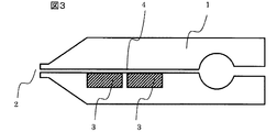
- Example 3 After preparing positive and negative electrode slurries in the same manner as in Example 1, a die head (FIG. 3) with two rows of Fe-based fine metal foreign matter capturing mechanisms of permanent magnets attached was used, and the die head gap was changed to 0.3 mm.
- the cylindrical lithium secondary battery was assembled in the same manner as in Example 1. When this battery was tested and evaluated in the same manner as in Example 1, the defective rate was 0.02 to 0.05%. Further, when the defective batteries were investigated, the cause of the defects was 1/50 or less due to the Fe-based metal particles.
- the reliability of the lithium secondary battery can be greatly improved by capturing the Fe-based fine metal foreign matter at the die head portion.
- the lithium transition metal composite oxide of the positive electrode active material is exemplified by a composite oxide of lithium, manganese, cobalt, and nickel, but the present invention is not limited to this.
- a lithium manganese complex oxide having a spinel crystal structure or a layered crystal structure, or a part of manganese or lithium in the crystal for example, Fe, Co, Ni, Cr, Al, Mg, etc.
- a material substituted or doped with the above element, or a material obtained by substituting or doping part of oxygen in the crystal with an element such as S or P can be given.
- PVDF polytetrafluoroethylene
- PTFE polytetrafluoroethylene
- polyethylene polyethylene
- polystyrene polystyrene
- polybutadiene butyl rubber
- Polymers such as nitrile rubber, styrene / butadiene rubber, polysulfide rubber, nitrocellulose, cyanoethyl cellulose, various latexes, acrylonitrile, vinyl fluoride, vinylidene fluoride, propylene fluoride, chloroprene, and mixtures thereof Can be mentioned.
- NMP is exemplified as the solvent, it is not limited to this.
- the removal of Fe-based fine metal foreign matter in the lithium battery electrode film slurry can be realized, so that it is possible to provide a highly reliable lithium battery and use such a lithium battery.
- the safety of the equipment and devices that were used can also be improved.
Landscapes
- Engineering & Computer Science (AREA)
- Manufacturing & Machinery (AREA)
- Chemical & Material Sciences (AREA)
- Chemical Kinetics & Catalysis (AREA)
- Electrochemistry (AREA)
- General Chemical & Material Sciences (AREA)
- Battery Electrode And Active Subsutance (AREA)
- Secondary Cells (AREA)
Abstract
製造工程での混入するFe系微小金属異物によって内部短絡が発生しリチウム二次電池の信頼性が低下する。 ダイヘッド部で電極膜スラリー中に混入したFe系微小金属異物を除去することで、リチウム電池電極膜スラリー中に混入したFe系微小金属異物の除去できるので、内部短絡事故のない信頼性が高いリチウム電池を提供することができる。
Description
本発明は、信頼性の高いリチウム二次電池の製造方法に関するものである。
環境保護、省エネルギーの観点から、エンジンとモータを動力源として併用したハイブリッド電気自動車が開発、製品化されている。また、将来的には燃料電池をエンジン替わりに用いる燃料電池ハイブリッド自動車の開発も盛んになってきている。この電気ハイブリッド自動車のエネルギー源として、電気を繰り返し充電放電可能な二次電池は必須の技術である。
なかでも、リチウム二次電池はその動作電圧が高く高い出力を得やすいので有力な電池であり、今後ハイブリッド自動車の電源としてますます重要性が増してきている電池である。(例えば特許文献1、2参照)
ハイブリッド自動車用として用いられるリチウム二次電池としては信頼性が最も重要である。リチウム二次電池の製造時に信頼性に影響を与える項目として、製造工程での装置及び配管等からの微小金属粉末の混入がある。
金属粉末は電極膜を形成するためのスラリーに混じっていることがあり、金属粉末が混入した場合、充電放電を繰り返すうちに金属イオンとなって負極部にデンドライト状に析出し、やがて正極と負極を隔てるセパレータを破って正極に到達し内部短絡することで発火事故となることが知られている。
これら金属異物のうち製造工程の装置および配管から混入する微小異物の主なものはFe粉およびステンレス粉、すなわちFe系微小金属異物である。
本発明の目的は、製造工程での混入するFe系微小金属異物を除去することで、内部短絡による発火がない高信頼なリチウム二次電池を提供することにある。
本発明は、上記目的を達成するために、リチウム二次電池の製造工程でスラリーに混入するFe系微小金属異物を、ダイヘッド内でスラリーから磁石で捕捉することで除去する
。
。
本発明によれば、Fe系金属異物に起因した内部短絡の無い高信頼なリチウム二次電池を製造することが可能となる。
製造工程での混入Fe系微小金属異物について、内部短絡を起こす場合の寸法としては
、通常セパレータ厚さ以上および塗布乾燥後の電極膜厚の1/2以上のもので、概略25~30μm以上のものである。
、通常セパレータ厚さ以上および塗布乾燥後の電極膜厚の1/2以上のもので、概略25~30μm以上のものである。
ここで、一般にリチウム二次電池の電極膜の活物質材の大きさとしては粒度分布として大きい粒子側(累積95%粒径)では30μm程度であることから、フィルタでは上記述べたFe系微小金属異物の除去が出来ないため、磁石による捕捉が必要となる。
磁石によるFe系微小金属異物の捕捉について、1.0Tの磁石を用いた場合のFe粒子の磁石面からの位置とFe粒子が磁石面に捕捉されるまでの移動距離(捕捉距離)を計算した結果を図1に示す。計算は、Feが混入したスラリーの粘度は5000cps、流速は20cm/秒の場合であるが、Fe粒子の磁石面からの位置が小さい、すなわち磁石面に近いほど捕捉距離は小さくなる。
また、実際にFe系微小金属異物が混入したスラリーではFe系微小金属異物が磁石面に捕捉される際に他の粒子、すなわち活物質粒子と衝突し磁石面への移動が妨げられるため、捕捉距離は磁石面から離れれば離れるほどほど捕捉距離は計算結果より大きくなり、1mmギャップで概略2~4倍、2mmギャップでは概略6~15倍となる。すなわちFe系微小金属異物が混入したスラリーでは磁石面からの距離を出来るだけ小さくすることが必要である。一般に、配管部での磁石によるFe系金属異物の捕捉では、磁石面と配管内面とのギャップは約5~10mmであり、計算結果より、大幅に捕捉距離は大きくなる
。
。
また、Fe系微小金属異物は装置および配管接続部より混入することから極力最後の段階、すなわち電極膜の塗布直前で行うことが望ましい。
以上から、Fe系微小金属異物が混入したスラリー中のFe系微小金属異物の除去としては磁石面からのギャップが小さく、かつ、塗布直前となるダイヘッド部で行うことが最適である。ダイヘッド部で行う場合、ギャップが0.5mm程度とかなり磁石面からの距離が小さいため、効率良くFe系微小金属異物の捕捉が可能となる。例えば図1に従えば
、30μmのFe異物は捕捉距離は13mm程度、また20μmのFe異物は捕捉距離は30mm程度であることがわかる。前述したが、実際の系では捕捉距離が計算結果よりも大きくなるので、磁石面を大きくする、たとえば磁力面を複数列にすることが効果的である。
、30μmのFe異物は捕捉距離は13mm程度、また20μmのFe異物は捕捉距離は30mm程度であることがわかる。前述したが、実際の系では捕捉距離が計算結果よりも大きくなるので、磁石面を大きくする、たとえば磁力面を複数列にすることが効果的である。
なお、磁力としては大きくかつ磁場勾配が大きければ捕捉距離は小さくなるが、概略磁力としては2000ガウス(0.2T)以上であればよいが、Fe以外のSUS異物を捕捉することも必要なことから捕捉部分の磁場としては0.3T以上であることが望ましい
。また磁場勾配としては、一般的な永久磁石での磁場勾配である1~3T/cm程度であれば良い。
。また磁場勾配としては、一般的な永久磁石での磁場勾配である1~3T/cm程度であれば良い。
また、磁石としては、永久磁石、電磁石、超伝導磁石等があるが、上記述べたように、0.3T以上の磁場を必要とする長さで発生させることが出来れば良い。
さらに、電磁石や超伝導磁石では磁力を0とすれば捕捉されたFe系微小金属異物は容易にスラリーで押し出され取り除くことが可能である。永久磁石でも着脱可能とすれば容易に捕捉されたFe系微小金属異物の除去が可能となる。
さらに、捕捉されなかったFe系微小金属異物は塗布電極膜表面側に存在するよりも塗布電極膜の箔側に存在したほうが内部短絡になりにくいことから、ダイヘッドの下側、すなわち箔側に除鉄機構が設置されているほうが好ましい。
〔各実施例の説明〕
以上、本発明に係るFe系微小金属異物除去についての方法を説明したが、リチウム電池を製造して評価した結果について以下に述べる。
〔各実施例の説明〕
以上、本発明に係るFe系微小金属異物除去についての方法を説明したが、リチウム電池を製造して評価した結果について以下に述べる。
正極電極膜のスラリーは、正極活物質としてリチウム遷移金属複合酸化物のリチウムマンガンコバルトニッケル複合酸化物(LiMnCoNiO)粉末を用いた。粉末サイズとしては平均粒子径(D50)が9.6μm、累積90%粒径(D90)が16.0μm、累積95%粒径(D95)が18.5μmであった。このリチウムマンガンコバルトニッケル複合酸化物を85重量部に対して、導電材として黒鉛粉末を9重量部およびカーボンブラックを2重量部とを混合して正極合剤を調製した。この正極合剤にポリフッ化ビニリデン(以下、PVDFと略記する。)が4重量部となるようにポリフッ化ビニリデンを溶
解したN-メチル-2-ピロリドン(以下、NMPと略記する。)溶液(バインダ溶液)
を加えるとともにNMPに分散させてスラリー状とした。スラリーの固形分濃度32vol%,粘度は22000cpsであった。
解したN-メチル-2-ピロリドン(以下、NMPと略記する。)溶液(バインダ溶液)
を加えるとともにNMPに分散させてスラリー状とした。スラリーの固形分濃度32vol%,粘度は22000cpsであった。
同様に負極電極膜のスラリーは、負極活物質として平均粒子径(D50)が9.5μm
、累積90%粒径(D90)が16.5μm、累積95%粒径(D95)が20.2μmであった。この非晶質炭素粉末90重量部、導電材としてカーボンブラックを5重量部とを混合して負極合剤を調製した。この負極合剤にPVDFが5重量部となるようにバインダ溶液を加えるとともにNMPに分散させてスラリー状とした。スラリーの固形分濃度30vol%,粘度は2000cpsであった。
、累積90%粒径(D90)が16.5μm、累積95%粒径(D95)が20.2μmであった。この非晶質炭素粉末90重量部、導電材としてカーボンブラックを5重量部とを混合して負極合剤を調製した。この負極合剤にPVDFが5重量部となるようにバインダ溶液を加えるとともにNMPに分散させてスラリー状とした。スラリーの固形分濃度30vol%,粘度は2000cpsであった。
続いて、これら正極スラリー及び負極スラリーを永久磁石のFe系微小金属異物の捕捉機構を付けたダイヘッド(図2)を用いて塗布をおこなった。ダイヘッド1はその内部にスラリーが流れるスラリー流路4と、スラリー流路4からスラリーが吐出されるスラリー吐出部2と、スラリー流路4に隣接されて配置された磁石序鉄部とを備えている。このときのダイヘッドのギャップは0.5mm、Fe系微小金属異物の捕捉部分の0.3T以上の磁場部分の距離は25~28mmであった。
塗布乾燥後膜厚としては60~70μmで、正極はアルミ箔に、また負極は銅箔に塗布
, 乾燥, ローラープレスして正極電極及び負極電極を作製した。
, 乾燥, ローラープレスして正極電極及び負極電極を作製した。
次に、厚み30μm、空孔率が45%のポリエチレンから成る微多孔性セパレータを
挟んで上記の正極と負極を渦巻き状に捲回して電極群を作製した。この電極群にリードを取り付けて有底円筒状の容器(電池缶)に収容し、さらに非水電解液を封入することにより、円筒形リチウム二次電池を組立てた。
〔比較例〕
実施例1と異なるのは、ダイヘッド部に永久磁石のFe系微小金属異物の捕捉機構がつ
いていないのみで、その他はすべて実施例1と同様に円筒形リチウム二次電池を組立てた
。
〔試験・評価〕
実施例1及び比較例の電池について、所定回数の充放電を繰り返した後の充電した電池について、10日間放置した時点での電圧低下率が5mV/day以上のものを不良とした場合、実施例1では0.3%以下の不良率であるのに対し比較例では0.7~1.0%であった。
挟んで上記の正極と負極を渦巻き状に捲回して電極群を作製した。この電極群にリードを取り付けて有底円筒状の容器(電池缶)に収容し、さらに非水電解液を封入することにより、円筒形リチウム二次電池を組立てた。
〔比較例〕
実施例1と異なるのは、ダイヘッド部に永久磁石のFe系微小金属異物の捕捉機構がつ
いていないのみで、その他はすべて実施例1と同様に円筒形リチウム二次電池を組立てた
。
〔試験・評価〕
実施例1及び比較例の電池について、所定回数の充放電を繰り返した後の充電した電池について、10日間放置した時点での電圧低下率が5mV/day以上のものを不良とした場合、実施例1では0.3%以下の不良率であるのに対し比較例では0.7~1.0%であった。
なお、実施例1での不良電池について調査したところ、不良原因がFe系微小金属異物によるものは1/5以下であったのに対し、比較例1では全不良の約3/5がFe系微小金属異物によるものであった。
実施例1と同様にして正負極スラリーを作製した後、ダイヘッドのギャップを0.3mmに変更して塗工し、実施例1と同様に円筒形リチウム二次電池を組立てた。この電池について実施例1と同様の試験・評価をしたところ不良率は0.05~0.2%であった。また、不良電池について調査したところ、不良原因がFe系微小金属異物によるものは1/20以下であった。
実施例1と同様にして正負極スラリーを作製した後、永久磁石のFe系微小金属異物の捕捉機構を2列取り付けたダイヘッド(図3)を用い、ダイヘッドのギャップを0.3mmに変更して塗工し、実施例1と同様に円筒形リチウム二次電池を組立てた。この電池について実施例1と同様の試験・評価をしたところ不良率は0.02~0.05%であった
。また、不良電池において調査したところ、不良原因がFe系金属粒子によるものは1/50以下であった。
。また、不良電池において調査したところ、不良原因がFe系金属粒子によるものは1/50以下であった。
以上説明したように、ダイヘッド部でFe系微小金属異物を捕捉することでリチウム二次電池の信頼性が大幅に向上できることがわかる。
また、本実施形態では、正極活物質のリチウム遷移金属複合酸化物にリチウム、マンガン、コバルト、ニッケルの複合酸化物を例示したが、本発明はこれに限定されるものではない。本実施形態以外でも、例えば、スピネル結晶構造や層状結晶構造のリチウムマンガン複酸化物や、結晶中のマンガンやリチウムの一部をそれら以外の例えば、Fe、Co、Ni、Cr、Al、Mg等の元素で置換又はドープした材料、結晶中の酸素の一部をS、P等の元素で置換又はドープした材料を挙げることができる。
また更に、本実施形態ではバインダとしてPVDFの例を示したが、ポリテトラフルオロエチレン(PTFE)、ポリエチレン、ポリスチレン、ポリブタジエン、ブチルゴム、
ニトリルゴム、スチレン/ブタジエンゴム、多硫化ゴム、ニトロセルロ-ス、シアノエチルセルロース、各種ラテックス、アクリロニトリル、フッ化ビニル、フッ化ビニリデン、フッ化プロピレン、フッ化クロロプレン等の重合体及びこれらの混合体等を挙げることができる。
ニトリルゴム、スチレン/ブタジエンゴム、多硫化ゴム、ニトロセルロ-ス、シアノエチルセルロース、各種ラテックス、アクリロニトリル、フッ化ビニル、フッ化ビニリデン、フッ化プロピレン、フッ化クロロプレン等の重合体及びこれらの混合体等を挙げることができる。
また同様に、溶媒としてNMPについて例示したが、これに限定されるものではない。
上記の通り、本発明によれば、リチウム電池電極膜スラリー中のFe系微小金属異物の除去が実現できるので、信頼性が高いリチウム電池を提供することができるとともに、このようなリチウム電池を用いた機器・装置の安全性も向上することが出来る。
1…ダイヘッド、2…スラリー吐出部、3…磁石除鉄部、4…スラリー流路。
Claims (10)
- 除鉄手段付ダイヘッド部でスラリー中に混入したFe系金属異物を除去しながら、当該ダイヘッドを通して前記スラリーを金属箔に塗布し、乾燥させる工程と、
前記スラリーを塗布した金属箔でセパレータを挟ませて電極群を作製する工程と、
前記作製した電極を容器に収容し、非水溶液を封入する工程と、
を含むことを特徴とするリチウム二次電池の製造方法。 - 請求項1において、
前記電極群を作成する工程では、前記金属箔を渦巻き状に巻き回し、
前記容器は電池缶であることを特徴とするリチウム二次電池の製造方法。 - 請求項1において、
前記除鉄手段は、磁力により前記Fe系金属異物を除去することを特徴とするリチウム
二次電池の製造方法。 - 請求項3において、
前記除鉄手段付ダイヘッド部の除鉄部が1列または複数列であることを特徴とする、リ
チウム二次電池の製造方法。 - 請求項3において、
前記除鉄手段付ダイヘッド部のスラリー通過部の磁力が3000ガウス以上であること
を特徴とするリチウム二次電池の製造方法。 - 請求項3において、
前記除鉄手段の磁力発生部が永久磁石または電磁石であることを特徴とするリチウム二
次電池の製造方法。 - 請求項3において、
前記除鉄手段部の磁力発生部が着脱可能であることを特徴とするリチウム二次電池の製
造方法。 - 請求項1において、
前記スラリーは、活物質、導電助材、バインダおよび水または有機溶剤からなる組成で
粘度が500~40000cpsであることを特徴とするリチウム二次電池の製造方法。 - 請求項7において、
前記バインダおよび前記有機溶剤が、ポリフッ化ビニリデンおよびN‐メチル‐2‐ピ
ロリドンであることを特徴とする、リチウム二次電池の製造方法。 - 除鉄手段付ダイヘッド部でスラリー中に混入したFe系金属異物を除去しながら、当該ダイヘッドを通して前記スラリーを金属箔に塗布し、乾燥させる工程と、
前記スラリーを塗布した金属箔でセパレータを挟む工程と、
を含むことを特徴とするリチウム二次電池の電極膜の製造方法。
Priority Applications (1)
| Application Number | Priority Date | Filing Date | Title |
|---|---|---|---|
| CN200980148948.9A CN102239595B (zh) | 2008-12-08 | 2009-12-04 | 锂二次电池的制造方法 |
Applications Claiming Priority (2)
| Application Number | Priority Date | Filing Date | Title |
|---|---|---|---|
| JP2008-311716 | 2008-12-08 | ||
| JP2008311716A JP5372478B2 (ja) | 2008-12-08 | 2008-12-08 | リチウム二次電池の製造方法 |
Publications (1)
| Publication Number | Publication Date |
|---|---|
| WO2010067559A1 true WO2010067559A1 (ja) | 2010-06-17 |
Family
ID=42242554
Family Applications (1)
| Application Number | Title | Priority Date | Filing Date |
|---|---|---|---|
| PCT/JP2009/006619 Ceased WO2010067559A1 (ja) | 2008-12-08 | 2009-12-04 | リチウム二次電池の製造方法 |
Country Status (3)
| Country | Link |
|---|---|
| JP (1) | JP5372478B2 (ja) |
| CN (1) | CN102239595B (ja) |
| WO (1) | WO2010067559A1 (ja) |
Cited By (5)
| Publication number | Priority date | Publication date | Assignee | Title |
|---|---|---|---|---|
| JP2013505193A (ja) * | 2009-09-18 | 2013-02-14 | エー123 システムズ, インコーポレイテッド | リン酸第二鉄およびその調製の方法 |
| CN103567107A (zh) * | 2012-08-08 | 2014-02-12 | 深圳市沃特玛电池有限公司 | 可去除磷酸铁锂电池中杂质的涂布机 |
| US9660267B2 (en) | 2009-09-18 | 2017-05-23 | A123 Systems, LLC | High power electrode materials |
| WO2024125398A1 (zh) * | 2022-12-16 | 2024-06-20 | 蔚来电池科技(安徽)有限公司 | 一种用于制备锂电池的浆料输送及涂布装置 |
| EP4503158A4 (en) * | 2022-12-13 | 2026-02-25 | Lg Energy Solution Ltd | DEVICE FOR MAKING A NEGATIVE ELECTRODE FOR A RECHARGEABLE BATTERY |
Families Citing this family (7)
| Publication number | Priority date | Publication date | Assignee | Title |
|---|---|---|---|---|
| US20130280413A1 (en) * | 2011-01-13 | 2013-10-24 | Yozo Uchida | Electrode material applying apparatus and filtering apparatus |
| WO2014142045A1 (ja) * | 2013-03-14 | 2014-09-18 | 日本ゼオン株式会社 | 電気化学素子電極用複合粒子の製造方法 |
| KR101795117B1 (ko) | 2014-05-27 | 2017-11-07 | 주식회사 엘지화학 | 전지 제조 장치 |
| CN108134126A (zh) * | 2017-11-29 | 2018-06-08 | 清华大学 | 电池内短路的触发方法 |
| JP7522146B2 (ja) * | 2022-02-14 | 2024-07-24 | プライムアースEvエナジー株式会社 | 電極体の製造装置及び電極体の製造方法 |
| KR20240087992A (ko) * | 2022-12-13 | 2024-06-20 | 주식회사 엘지에너지솔루션 | 이차전지용 음극 제조장치 |
| WO2025192226A1 (ja) * | 2024-03-11 | 2025-09-18 | 出光興産株式会社 | 硫化物固体電解質の製造方法及び製造装置 |
Citations (4)
| Publication number | Priority date | Publication date | Assignee | Title |
|---|---|---|---|---|
| JP2003123742A (ja) * | 2001-10-11 | 2003-04-25 | Mitsubishi Chemicals Corp | 非水電解液二次電池用電極板の製造方法 |
| JP2006286404A (ja) * | 2005-03-31 | 2006-10-19 | Dainippon Printing Co Ltd | 非水電解液二次電池用電極板の正極板と負極板の組み合わせ、その正極板と負極板の製造方法、および非水電解液二次電池 |
| JP2008152946A (ja) * | 2006-12-14 | 2008-07-03 | Matsushita Electric Ind Co Ltd | 非水系二次電池用電極群の製造方法およびその製造装置 |
| JP2009164062A (ja) * | 2008-01-10 | 2009-07-23 | Panasonic Corp | 非水系二次電池およびその製造装置 |
Family Cites Families (6)
| Publication number | Priority date | Publication date | Assignee | Title |
|---|---|---|---|---|
| CN101242007A (zh) * | 2007-02-06 | 2008-08-13 | 深圳市比克电池有限公司 | 一种锂离子电池制造方法 |
| CN201082373Y (zh) * | 2007-04-10 | 2008-07-09 | 深圳市比克电池有限公司 | 一种流体过滤系统 |
| CN201036773Y (zh) * | 2007-04-25 | 2008-03-19 | 上海比亚迪有限公司 | 一种涂布机 |
| CN101294198A (zh) * | 2007-04-27 | 2008-10-29 | 上海人类基因组研究中心 | 冠心病检测方法和试剂盒 |
| CN201103795Y (zh) * | 2007-09-25 | 2008-08-20 | 深圳市比克电池有限公司 | 一种电池浆料运送装置 |
| JP4687833B2 (ja) * | 2008-09-18 | 2011-05-25 | 日本ゼオン株式会社 | 二次電池電極用バインダー組成物およびその製造方法 |
-
2008
- 2008-12-08 JP JP2008311716A patent/JP5372478B2/ja not_active Expired - Fee Related
-
2009
- 2009-12-04 CN CN200980148948.9A patent/CN102239595B/zh not_active Expired - Fee Related
- 2009-12-04 WO PCT/JP2009/006619 patent/WO2010067559A1/ja not_active Ceased
Patent Citations (4)
| Publication number | Priority date | Publication date | Assignee | Title |
|---|---|---|---|---|
| JP2003123742A (ja) * | 2001-10-11 | 2003-04-25 | Mitsubishi Chemicals Corp | 非水電解液二次電池用電極板の製造方法 |
| JP2006286404A (ja) * | 2005-03-31 | 2006-10-19 | Dainippon Printing Co Ltd | 非水電解液二次電池用電極板の正極板と負極板の組み合わせ、その正極板と負極板の製造方法、および非水電解液二次電池 |
| JP2008152946A (ja) * | 2006-12-14 | 2008-07-03 | Matsushita Electric Ind Co Ltd | 非水系二次電池用電極群の製造方法およびその製造装置 |
| JP2009164062A (ja) * | 2008-01-10 | 2009-07-23 | Panasonic Corp | 非水系二次電池およびその製造装置 |
Cited By (7)
| Publication number | Priority date | Publication date | Assignee | Title |
|---|---|---|---|---|
| JP2013505193A (ja) * | 2009-09-18 | 2013-02-14 | エー123 システムズ, インコーポレイテッド | リン酸第二鉄およびその調製の方法 |
| US9660267B2 (en) | 2009-09-18 | 2017-05-23 | A123 Systems, LLC | High power electrode materials |
| US9954228B2 (en) | 2009-09-18 | 2018-04-24 | A123 Systems, LLC | High power electrode materials |
| US10522833B2 (en) | 2009-09-18 | 2019-12-31 | A123 Systems, LLC | High power electrode materials |
| CN103567107A (zh) * | 2012-08-08 | 2014-02-12 | 深圳市沃特玛电池有限公司 | 可去除磷酸铁锂电池中杂质的涂布机 |
| EP4503158A4 (en) * | 2022-12-13 | 2026-02-25 | Lg Energy Solution Ltd | DEVICE FOR MAKING A NEGATIVE ELECTRODE FOR A RECHARGEABLE BATTERY |
| WO2024125398A1 (zh) * | 2022-12-16 | 2024-06-20 | 蔚来电池科技(安徽)有限公司 | 一种用于制备锂电池的浆料输送及涂布装置 |
Also Published As
| Publication number | Publication date |
|---|---|
| CN102239595A (zh) | 2011-11-09 |
| JP2010135238A (ja) | 2010-06-17 |
| CN102239595B (zh) | 2014-11-05 |
| JP5372478B2 (ja) | 2013-12-18 |
Similar Documents
| Publication | Publication Date | Title |
|---|---|---|
| JP5372478B2 (ja) | リチウム二次電池の製造方法 | |
| KR101543937B1 (ko) | 리튬 이온 2차 전지와 그 제조 방법 | |
| US11264649B2 (en) | Cylindrical nonaqueous electrolyte secondary battery | |
| US12341187B2 (en) | Non-aqueous electrolyte secondary battery | |
| US20170324089A9 (en) | Electrode material, method for producing the same, and lithium battery | |
| KR101573994B1 (ko) | 전극 재료 도포 장치 및 여과 장치 | |
| JPWO2012039041A1 (ja) | 非水電解質二次電池 | |
| JP2013182712A (ja) | 非水電解質二次電池とその製造方法 | |
| JPWO2011070661A1 (ja) | 電池用電極の製造方法 | |
| JP2013069432A (ja) | リチウムイオン二次電池とその製造方法 | |
| CN101485034A (zh) | 锂二次电池 | |
| WO2013088824A1 (ja) | リチウムイオン電池およびその製造方法 | |
| CN105900276A (zh) | 锂离子二次电池的制造方法 | |
| JP2012109028A (ja) | リチウムイオン二次電池およびその製造方法 | |
| JP6307594B2 (ja) | リチウムイオン二次電池及びその製造方法と製造装置 | |
| JP5317544B2 (ja) | リチウム二次電池の製造方法 | |
| Wang et al. | Particles released by abused prismatic Ni-rich automotive lithium-ion batteries | |
| JP6478112B2 (ja) | 非水電解質二次電池の製造方法 | |
| JP5348488B2 (ja) | 電池用電極の製造方法 | |
| JP2018022564A (ja) | 二次電池の検査方法 | |
| JP2007141590A (ja) | 非水電解質二次電池および非水電解質二次電池用電極群の製造方法 | |
| Wang et al. | Soil pollution element content and size distribution of particles released by abused prismatic Ni-rich automotive lithium-ion batteries | |
| JP2015015084A (ja) | 二次電池の製造方法 | |
| JP6324418B2 (ja) | リチウムイオン電池 | |
| KR102033518B1 (ko) | 비수전해질 이차 전지 |
Legal Events
| Date | Code | Title | Description |
|---|---|---|---|
| WWE | Wipo information: entry into national phase |
Ref document number: 200980148948.9 Country of ref document: CN |
|
| 121 | Ep: the epo has been informed by wipo that ep was designated in this application |
Ref document number: 09831667 Country of ref document: EP Kind code of ref document: A1 |
|
| NENP | Non-entry into the national phase |
Ref country code: DE |
|
| 122 | Ep: pct application non-entry in european phase |
Ref document number: 09831667 Country of ref document: EP Kind code of ref document: A1 |