WO2010058576A1 - 永久磁石式回転電機 - Google Patents
永久磁石式回転電機 Download PDFInfo
- Publication number
- WO2010058576A1 WO2010058576A1 PCT/JP2009/006216 JP2009006216W WO2010058576A1 WO 2010058576 A1 WO2010058576 A1 WO 2010058576A1 JP 2009006216 W JP2009006216 W JP 2009006216W WO 2010058576 A1 WO2010058576 A1 WO 2010058576A1
- Authority
- WO
- WIPO (PCT)
- Prior art keywords
- permanent magnet
- magnetic
- magnet
- permanent
- type rotating
- Prior art date
Links
- 230000004907 flux Effects 0.000 claims abstract description 122
- 230000005415 magnetization Effects 0.000 claims abstract description 67
- 230000002829 reductive effect Effects 0.000 claims abstract description 35
- 238000004804 winding Methods 0.000 claims abstract description 35
- 230000008859 change Effects 0.000 claims description 19
- 230000007423 decrease Effects 0.000 claims description 10
- 230000002427 irreversible effect Effects 0.000 claims description 6
- 230000005347 demagnetization Effects 0.000 abstract description 15
- 230000002441 reversible effect Effects 0.000 abstract description 14
- 229910000859 α-Fe Inorganic materials 0.000 description 22
- BGPVFRJUHWVFKM-UHFFFAOYSA-N N1=C2C=CC=CC2=[N+]([O-])C1(CC1)CCC21N=C1C=CC=CC1=[N+]2[O-] Chemical compound N1=C2C=CC=CC2=[N+]([O-])C1(CC1)CCC21N=C1C=CC=CC1=[N+]2[O-] BGPVFRJUHWVFKM-UHFFFAOYSA-N 0.000 description 21
- 230000009471 action Effects 0.000 description 16
- 229910001172 neodymium magnet Inorganic materials 0.000 description 15
- 230000002093 peripheral effect Effects 0.000 description 15
- 230000004888 barrier function Effects 0.000 description 10
- 230000000694 effects Effects 0.000 description 10
- 229910000828 alnico Inorganic materials 0.000 description 8
- XEEYBQQBJWHFJM-UHFFFAOYSA-N Iron Chemical compound [Fe] XEEYBQQBJWHFJM-UHFFFAOYSA-N 0.000 description 5
- 238000010586 diagram Methods 0.000 description 5
- 238000000034 method Methods 0.000 description 4
- RYGMFSIKBFXOCR-UHFFFAOYSA-N Copper Chemical compound [Cu] RYGMFSIKBFXOCR-UHFFFAOYSA-N 0.000 description 2
- 229910000976 Electrical steel Inorganic materials 0.000 description 2
- 230000008901 benefit Effects 0.000 description 2
- 229910052802 copper Inorganic materials 0.000 description 2
- 239000010949 copper Substances 0.000 description 2
- 230000003247 decreasing effect Effects 0.000 description 2
- 229910052742 iron Inorganic materials 0.000 description 2
- 238000010030 laminating Methods 0.000 description 2
- 230000009467 reduction Effects 0.000 description 2
- 229910000938 samarium–cobalt magnet Inorganic materials 0.000 description 2
- 230000003313 weakening effect Effects 0.000 description 2
- XAGFODPZIPBFFR-UHFFFAOYSA-N aluminium Chemical compound [Al] XAGFODPZIPBFFR-UHFFFAOYSA-N 0.000 description 1
- 229910052782 aluminium Inorganic materials 0.000 description 1
- 238000005266 casting Methods 0.000 description 1
- 230000005389 magnetism Effects 0.000 description 1
- 238000004519 manufacturing process Methods 0.000 description 1
- 239000000463 material Substances 0.000 description 1
- 230000000149 penetrating effect Effects 0.000 description 1
- 230000002040 relaxant effect Effects 0.000 description 1
- 230000001360 synchronised effect Effects 0.000 description 1
Images


Classifications
-
- H—ELECTRICITY
- H02—GENERATION; CONVERSION OR DISTRIBUTION OF ELECTRIC POWER
- H02K—DYNAMO-ELECTRIC MACHINES
- H02K1/00—Details of the magnetic circuit
- H02K1/06—Details of the magnetic circuit characterised by the shape, form or construction
- H02K1/22—Rotating parts of the magnetic circuit
- H02K1/27—Rotor cores with permanent magnets
- H02K1/2706—Inner rotors
- H02K1/272—Inner rotors the magnetisation axis of the magnets being perpendicular to the rotor axis
- H02K1/274—Inner rotors the magnetisation axis of the magnets being perpendicular to the rotor axis the rotor consisting of two or more circumferentially positioned magnets
- H02K1/2753—Inner rotors the magnetisation axis of the magnets being perpendicular to the rotor axis the rotor consisting of two or more circumferentially positioned magnets the rotor consisting of magnets or groups of magnets arranged with alternating polarity
- H02K1/276—Magnets embedded in the magnetic core, e.g. interior permanent magnets [IPM]
- H02K1/2766—Magnets embedded in the magnetic core, e.g. interior permanent magnets [IPM] having a flux concentration effect
Definitions
- the present invention uses two or more types of permanent magnets, and irreversibly changes the amount of magnetic flux of at least one of the permanent magnets, thereby enabling a variable speed operation in a wide range from low speed to high speed. It relates to a rotating electrical machine.
- a surface magnet type permanent magnet type rotating electrical machine in which a permanent magnet is attached to the outer periphery of a rotor core
- an embedded type permanent magnet type rotating electrical machine in which a permanent magnet is embedded in a rotor core.
- an embedded permanent magnet type rotating electrical machine is suitable.
- the interlinkage magnetic flux of the permanent magnet is always generated with a constant strength, so that the induced voltage by the permanent magnet increases in proportion to the rotational speed. Therefore, when variable speed operation is performed from low speed to high speed, the induced voltage (back electromotive voltage) by the permanent magnet becomes extremely high at high speed rotation.
- the induced voltage by the permanent magnet is applied to the electronic component of the inverter and exceeds its withstand voltage, the electronic component breaks down. For this reason, it is conceivable to perform a design in which the amount of magnetic flux of the permanent magnet is reduced so as to be equal to or less than the withstand voltage.
- variable speed operation When performing variable speed operation close to constant output from low speed to high speed, the interlinkage magnetic flux on the right of the permanent magnet is constant, so the rotating electrical machine voltage reaches the upper limit of the power supply voltage in the high-speed rotation range, and the current required for output flows. Disappear. As a result, the output is greatly reduced in the high-speed rotation region, and further, variable speed operation cannot be performed over a wide range up to high-speed rotation.
- the total amount of interlinkage magnetic flux of the armature winding is composed of a magnetic flux caused by a d-axis current and a magnetic flux caused by a permanent magnet.
- the flux weakening control by generating a magnetic flux due to a negative d-axis current, the total flux linkage is reduced by the magnetic flux due to this negative d-axis current.
- the permanent magnet having a high coercive force changes the operating point of the magnetic characteristics (BH characteristics) within a reversible range. For this reason, the NdFeB magnet having a high coercive force is applied to the permanent magnet so that the permanent magnet is not irreversibly demagnetized by the demagnetizing field of the magnetic flux control.
- the linkage flux decreases due to the negative d-axis current flux, so the decrease in linkage flux creates a voltage margin relative to the upper voltage limit. And since the electric current which becomes a torque component can be increased, the output in a high speed region increases. Further, the rotational speed can be increased by the voltage margin, and the range of variable speed operation is expanded.
- the copper loss increases and the efficiency deteriorates.
- the demagnetizing field due to the negative d-axis current generates a harmonic magnetic flux, and the increase in the voltage generated by the harmonic magnetic flux or the like is weakened to create a limit of voltage reduction by the magnetic flux control. Therefore, even if the flux-weakening control is applied to the embedded permanent magnet type rotating electrical machine, it is difficult to operate at a variable speed of more than 3 times the base speed. Furthermore, there is a problem that the iron loss increases due to the above-described harmonic magnetic flux, and the efficiency is greatly lowered in the middle and high speed ranges. Further, there is a possibility that vibration is generated by electromagnetic force generated by the harmonic magnetic flux.
- the train When an embedded permanent magnet motor is applied to a train drive motor, the train has a state of coasting, and in the same way as the hybrid vehicle drive motor described above, in order to make the induced voltage by the permanent magnet less than the power supply voltage, the magnetic flux control is performed. Continue to flow negative d-axis current. In that case, since the electric motor generates only a loss, the overall operation efficiency deteriorates.
- Patent Documents 1 and 2 disclose a permanent magnet having a low coercive force (hereinafter, referred to as “magnetic coercive force”) whose magnetic flux density is irreversibly changed by a magnetic field generated by a current of a stator winding.
- Magnetic coercive force a low coercive force
- Fixed magnets high coercivity permanent magnets
- a technique is described in which the amount of total interlinkage magnetic flux is adjusted by magnetizing a variable magnetic magnet with a magnetic field generated by a current so that the total interlinkage magnetic flux between the magnet and the fixed magnetic magnet is reduced.
- the permanent magnet type rotating electrical machine disclosed in Patent Document 1 includes a rotor 1 having a configuration as shown in FIG. That is, the rotor 1 includes a rotor core 2, eight variable magnetic magnets 3, and eight fixed magnetic magnets 4.
- the rotor core 2 is configured by laminating silicon steel plates, the variable magnetic force magnet 3 is an alnico magnet or an FeCrCo magnet, and the fixed magnetic force magnet 4 is an NdFeB magnet.
- the variable magnetic force magnet 3 is embedded in the rotor core 2, and first cavities 5 are provided at both ends of the variable magnetic force magnet 3.
- the variable magnetic force magnet 3 is disposed along the radial direction of the rotor that coincides with the q axis serving as the central axis between the magnetic poles, and is magnetized in a direction perpendicular to the radial direction.
- the fixed magnetic magnet 4 is embedded in the rotor core 2, and second cavities 6 are provided at both ends of the fixed magnetic magnet 4.
- the fixed magnetic magnet 4 is disposed substantially in the circumferential direction of the rotor 1 so as to be sandwiched between the two variable magnetic magnets 3 on the inner peripheral side of the rotor 1.
- the fixed magnetic magnet 4 is magnetized in a direction substantially perpendicular to the circumferential direction of the rotor 1.
- the magnetic pole part 7 of the rotor core 2 is formed so as to be surrounded by two variable magnetic magnets 3 and one fixed magnetic magnet 4.
- the central axis direction of the magnetic pole part 7 of the rotor core 2 is the d axis, and the central axis direction between the magnetic poles is the q axis.
- a magnetic field is formed by passing a pulsed current having a very short energization time (about 100 ⁇ s to 1 ms) through the stator winding to make it variable.
- a magnetic field is applied to the magnetic magnet 3. If the magnetizing magnetic field is 250 kA / m, ideally, a sufficient magnetizing magnetic field acts on the variable magnetic force magnet 3, and the fixed magnetic force magnet 4 does not undergo irreversible demagnetization due to magnetization.
- the amount of interlinkage magnetic flux of the variable magnetic force magnet 3 can be greatly changed from the maximum to 0 by the d-axis current of the rotor 1, and the magnetization direction can be changed in both forward and reverse directions. . That is, assuming that the linkage magnetic flux of the fixed magnetic magnet 4 is in the positive direction, the linkage magnetic flux of the variable magnetic magnet 3 can be adjusted over a wide range from the maximum value in the positive direction to 0 and further in the reverse direction. Therefore, in the rotor of Patent Document 1, the total interlinkage magnetic flux combined with the variable magnetic magnet 3 and the fixed magnetic magnet 4 can be adjusted over a wide range by magnetizing the variable magnetic magnet 3 with the d-axis current.
- the variable magnetic magnet 3 is magnetized with the d-axis current so as to have the maximum value in the same direction (initial state) as the interlinkage magnetic flux of the fixed magnetic magnet 4, so that the torque by the permanent magnet becomes the maximum value. Therefore, the torque and output of the rotating electrical machine can be maximized.
- the voltage of the rotating electrical machine is lowered by reducing the amount of magnetic flux of the variable magnetic magnet 3 and lowering the total flux linkage, so that there is room for the upper limit of the power supply voltage and the rotational speed ( (Frequency) can be further increased.
- the amount of interlinkage magnetic flux of the variable magnetic force magnet 3 can be greatly changed from the maximum to 0 by the d-axis current of the rotor 1, and the magnetization direction is also positive. It has an excellent characteristic that it can be made in both opposite directions.
- magnetizing the variable magnetic force magnet 3 a large magnetizing current is required, which leads to an increase in the size of an inverter for driving the electric motor.
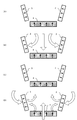
- FIGS. 16A to 16D are schematic diagrams for explaining this.
- the permanent magnet type rotating electric machine of Patent Document 1 as shown in FIG. 16A, two variable magnetic magnets 3 and one fixed magnetic magnet 4 are arranged in a U shape with the d axis as the center.
- the direction of the magnetic flux of the variable magnetic magnet 3 and the fixed magnetic magnet 4 is directed toward the central magnetic pole portion 7.
- the magnetic flux is changed from the outer peripheral side of the rotor 1 to the variable magnetic magnet 3 and the fixed magnetic magnet as shown in FIG. 4 so that the variable magnetic force magnet 3 is demagnetized.
- the fixed magnet 4 is not demagnetized because of its high coercivity.
- the permanent magnet type rotating electrical machine of Patent Document 1 since the permanent magnet type rotating electrical machine of Patent Document 1 has two types of magnets arranged in parallel magnetically, the amount of demagnetization of the variable magnetic force magnet 3 can be increased, and the change width of the magnetic force can be reduced to 0 to 0. Although there is an advantage that it can be increased to 100%, there is a problem that a large magnetizing current is required at the time of magnetization.
- the present invention has been made to solve the above-described problems, and by reducing the magnetizing current at the time of magnetizing the variable magnetic force magnet, it is possible to increase the speed of the inverter from low speed to high speed without requiring an increase in the size of the inverter. It is an object of the present invention to provide a permanent magnet type rotating electrical machine that can be operated at a variable speed in a wide range, can increase torque in a low-speed rotation region, increase output in a medium / high-speed rotation region, and improve efficiency.
- a rotor is formed by forming a plurality of magnetic poles in a rotor core using two or more kinds of permanent magnets having different products of coercive force and magnetization direction thickness.
- the permanent magnet type rotating electrical machine in which the stator composed of the armature core and the armature winding is disposed through the air gap has the following technical features. That is, among the two or more types of permanent magnets, a permanent magnet having a smaller product of coercive force and magnetization direction thickness than other permanent magnets has a smaller product, and a product of coercive force and magnetization direction thickness is different from that of other permanent magnets.
- a permanent magnet larger than a permanent magnet is defined as a permanent magnet having a large product
- two or more permanent magnets including the two or more types of permanent magnets are arranged in series on a magnetic circuit to form a magnet series.
- the permanent magnets having a large product are arranged in parallel on the magnetic circuit with respect to the magnet series, and among the permanent magnets forming the magnet series by the magnetic field created by the current of the armature winding, A permanent magnet having a small product is magnetized, and the amount of magnetic flux of the permanent magnet constituting the magnetic pole is irreversibly changed.
- two or more types of permanent magnets are arranged in series and parallel on each magnetic pole of the rotor, and two or more types of permanent magnets are arranged in series and parallel on the magnetic circuit between a plurality of magnetic poles. It is also possible. Further, it is possible to provide a magnetic barrier or a short-circuit coil for each magnetic pole.
- an increase in the magnetizing current at the time of demagnetization and magnetization of a permanent magnet having a small product of the coercive force and the magnetization direction thickness can be suppressed. Can be achieved.
- FIG. 3 is a cross-sectional view showing a state in which a variable magnetic force magnet is magnetized in the reverse direction by a reverse magnetic field caused by an electric current and the linkage flux of the magnet is minimum.
- Sectional drawing which shows the state which generate
- Sectional drawing which shows the state which reduced the magnetic force of the variable magnetic magnet which reversed the polarity with the magnetic field by an electric current.
- Sectional drawing which shows the state at the time of demagnetization in 1st Embodiment.
- Sectional drawing which shows the relationship between the magnetic barrier in this invention, and q-axis magnetic flux.
- action of the short circuit coil in this invention The schematic diagram which shows the structure of the 2nd Embodiment of this invention.
- FIG. 1 The schematic diagram which shows the effect
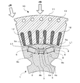
- the rotor 1 includes a rotor core 2, a permanent magnet 3 (hereinafter referred to as a variable magnetic force magnet) in which the product of the coercive force and the magnetization direction thickness is small, as shown in FIG. It is composed of permanent magnets (hereinafter referred to as fixed magnetic magnets) 4a and 4b in which the product of the coercive force and the magnetization direction thickness is large.
- 4a shows one fixed magnetic magnet arranged in series on the variable magnetic magnet 3 and the magnetic circuit
- 4b shows two pieces arranged in parallel on the variable magnetic magnet 3 and the magnetic circuit.
- a fixed magnetic magnet is shown.
- the rotor core 2 is formed by laminating silicon steel plates, and the variable magnetic magnet 3 and the fixed magnetic magnets 4 a and 4 b are embedded in the rotor core 2.
- a cavity is formed at the ends of the variable magnetic magnet 3 and the fixed magnetic magnets 4a and 4b so that the magnetic flux passing through the rotor core 2 passes through the portions of the variable magnetic magnet 3 and the fixed magnetic magnets 4a and 4b in the thickness direction. 5 and 6 are provided.
- the magnetic pole part 7 of the rotor core 2 is formed so as to be surrounded by one variable magnetic force magnet 3 and three fixed magnetic force magnets 4a, 4b, 4b.
- the central axis direction of the magnetic pole part 7 of the rotor core 2 is the d axis, and the central axis direction between the magnetic poles is the q axis.
- the variable magnetic magnet 3 can be a ferrite magnet or an alnico magnet.
- the fixed magnetic magnets 4a and 4b are NdFeB magnets.
- a case where a ferrite magnet having a coercive force of 280 kA / m is used for the variable magnetic magnet 3 and an NdFeB magnet having a coercive force of 1000 kA / m is used for the fixed magnetic magnets 4a and 4b will be described. .
- variable magnetic magnet 3 and the fixed magnetic magnet 4a are overlapped in the magnetization direction of each magnet to constitute one magnet. That is, the variable magnetic magnet 3 and the fixed magnetic magnet 4a are arranged in the same magnetic direction so as to overlap each other in series to form a series of magnets.
- This magnet series is arranged in the rotor core 2 at a position where the magnetization direction is the d-axis direction (here, substantially the radial direction of the rotor).
- the fixed magnetic magnets 4b and 4b are arranged on both sides of the variable magnetic magnet 3 and the fixed magnetic magnet 4a in series at positions where the magnetization direction is the d-axis direction.
- the fixed magnetic force magnets 4b and 4b arranged on the side constitute a parallel circuit on the magnetic circuit with respect to the magnet series. That is, on the magnetic circuit, the fixed magnetic force magnet 4a is arranged in series with the variable magnetic force magnet 3, and the fixed magnetic force magnets 4b and 4b are arranged in parallel.
- cavities 9 a and 9 b are provided in the outer peripheral portion and the inner peripheral portion of the fixed magnetic force magnets 4 b and 4 b of the rotor core 2. Among these, the cavity 9a in the outer peripheral portion of the fixed magnetic force magnets 4b and 4b extends along the arrangement direction of the fixed magnetic force magnets 4b and 4b, and forms a magnetic barrier.
- a short-circuit coil 8 is provided on the lower side (inner circumferential side of the rotor).
- the short-circuit coil 8 is set so that the magnetization direction of the fixed magnetic magnets 4b and 4b is the central axis.
- the short-circuit coil 8 is composed of a ring-shaped conductive member and is mounted so as to be fitted into the edge portions of the cavities 5 and 6 provided in the rotor core 2. It is also possible to manufacture by casting a conductive member melted at a high temperature into the hole of the rotor core 2.
- the short-circuit coil 8 is provided in the magnetic path portion of the other fixed magnetic magnets 4b and 4b excluding the variable magnetic magnet 3.
- the short-circuit coil 8 is a magnetic flux generated when a d-axis current is passed through the armature winding and generates a short-circuit current.
- the short-circuit current flowing in the short-circuit coil 8 preferably flows within 1 second with such a strength that the magnetization of the permanent magnet 3 to be irreversibly changed, and then attenuates 50% or more within 1 second. Further, when the inductance value and the resistance value of the short-circuit coil 8 are set to values that allow a short-circuit current to flow to the extent that the magnetization of the variable magnetic force magnet 3 changes, the efficiency is good.
- a stator 10 is provided on the outer periphery of the rotor 2 through an air gap.
- the stator 10 has an armature core 11 and an armature winding 12.
- reference numeral 13 denotes a cavity provided in the outer peripheral portion of the armature core 11.
- An induced current is induced in the short-circuit coil 8 by the magnetizing current flowing through the armature winding 12, and a magnetic flux penetrating the short-circuit coil 8 is formed by the induced current. Further, the magnetization direction of the variable magnetic force magnet 3 is irreversibly changed by the magnetization current flowing through the armature winding 12.
- variable magnetic magnet 3 for the variable magnetic magnet 3 and the fixed magnetic magnet 4a, during operation of the permanent magnet type rotating electric machine, the variable magnetic magnet 3 is magnetized by a magnetic field generated by the d-axis current, and the amount of the magnetic flux is irreversibly changed. .
- the d-axis current for magnetizing the variable magnetic force magnet 3 is passed, and at the same time, the torque of the rotating electrical machine is controlled by the q-axis current.
- the amount of interlinkage magnetic flux in the armature winding generated by the current (the total current obtained by combining the q-axis current and the d-axis current) and the variable magnetic magnet 3 and the fixed magnetic magnets 4a and 4b by the magnetic flux generated by the d-axis current. That is, the amount of interlinkage magnetic flux of the entire armature winding composed of the magnetic flux generated in the armature winding by the total current of the rotating electrical machine and the magnetic flux generated by the two or more kinds of permanent magnets 4a and 4b on the rotor side. Change almost reversibly.
- variable magnetic force magnet 3 is irreversibly changed by a magnetic field generated by an instantaneous large d-axis current.
- operation is carried out by continuously supplying a d-axis current in a range where little or no irreversible demagnetization occurs.
- the d-axis current at this time acts to adjust the terminal voltage by advancing the current phase.
- an operation control method is performed in which the polarity of the variable magnetic magnet 3 is reversed with a large d-axis current to advance the current phase.
- the variable magnetic force magnet 3 is not demagnetized but increased. Become. That is, the magnitude of the terminal voltage can be adjusted without demagnetizing the variable magnetic force magnet 3 with a negative d-axis current.
- a magnetic field is formed by applying a pulsed current whose energization time is extremely short (about 0.1 ms to 100 ms) to the armature winding of the stator, and the magnetic field is applied to the variable magnetic force magnet 3.
- a pulse current that forms a magnetic field for magnetizing the variable magnetic force magnet 3 is a d-axis current component of the armature winding of the stator.
- the change in the magnetization state of the permanent magnet due to the applied magnetic field due to the d-axis current varies depending on the magnitude of the coercive force. That is, the change in the magnetization state of the permanent magnet due to the applied magnetic field is approximated by the product of the magnitude of the coercive force and the thickness of the permanent magnet.
- the coercive force of the ferrite magnet is 300 kA / m
- the coercive force of the NdFeB magnet is 1000 kA / m.
- the magnet thickness in the magnetization direction is the same, 5 mm.
- the magnetomotive force required to change the magnetic force of the ferrite magnet that is the variable magnetic magnet 3 is about 20% of the NdFeB magnet that is the fixed magnetic magnets 4a and 4b. Therefore, the magnetic force of the NdFeB magnet can be maintained unchanged with a current that can change the magnetic force of the ferrite magnet. Thus, when these magnets are combined in series to form a magnet series, the total flux linkage of the permanent magnet can be adjusted by maintaining the magnetic force of the NdFeB magnet as a base and changing the magnetic force of the ferrite magnet. .
- a negative d-axis current that generates a magnetic field in the direction opposite to the magnetizing direction of the magnet is pulsed through the armature winding. If the magnetic field in the magnet changed by the negative d-axis current is 175 kA / m, the magnetic force of the ferrite magnet is irreversibly greatly reduced because the coercive force of the ferrite magnet is 175 kA / m. On the other hand, since the coercive force of the NdFeB magnet is 1500 kA / m, the magnetic force does not decrease irreversibly. As a result, when the pulsed d-axis current becomes 0, only the ferrite magnet is demagnetized, and the amount of flux linkage by the entire magnet can be reduced.
- a positive d-axis current that generates a magnetic field in the same direction as the magnetization direction of the permanent magnet is applied to the armature winding.
- a magnetic field necessary for magnetizing the ferrite magnet is generated. If the magnetic field in the magnet changed by the positive d-axis current is 350 kA / m, the demagnetized ferrite magnet is magnetized to generate the maximum magnetic force. On the other hand, since the coercive force of the NdFeB magnet is 1500 kA / m, the magnetic force does not change irreversibly. As a result, when the pulsed positive d-axis current becomes zero, only the ferrite magnet is magnetized, and the amount of flux linkage by the entire magnet can be increased. This makes it possible to return to the original maximum flux linkage.
- the magnetic force of the ferrite magnet is irreversibly changed, and the total interlinkage magnetic flux amount of the permanent magnet is arbitrarily changed. Is possible.
- variable magnetic force magnet 3 is magnetized so that the magnetic flux of the permanent magnet of the magnetic pole is added at the time of the maximum torque in the low speed region of the permanent magnet type rotating electric machine.
- the variable magnetic force magnet 3 is magnetized by a magnetic field caused by an electric current to reduce the magnetic flux.
- the induced electromotive force generated by the permanent magnet is used to withstand the inverter electronic component power source of the rotating electrical machine. Below voltage.
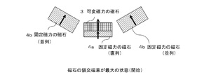
- FIG. 2 is a diagram when the maximum amount of flux linkage before demagnetization is obtained.
- the magnetization directions of the two kinds of laminated permanent magnets 3 and 4a are the same, the magnetic fluxes of both the permanent magnets 3 and 4a are added together to obtain the maximum amount of magnetic flux.
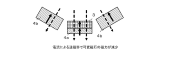
- FIG. 3 shows a state at the time of demagnetization, and the armature generates a negative d-axis current that generates a magnetic field in a direction opposite to the magnetization direction of both permanent magnets 3 and 4a from the d-axis direction by the armature winding.
- the magnetic field from the fixed magnetic field magnet 4a laminated on the variable magnetic field magnet 3 is applied to the variable magnetic field magnet 3 and this cancels out the magnetic field applied from the d-axis direction for demagnetization.
- the magnetization current for demagnetization is smaller than that at the time of magnetization, the increase in the magnetization current is small.
- FIG. 4 shows a state in which the magnetic force of the variable magnetic magnet 3 in a reverse magnetic field is reduced by a negative d-axis current.
- the magnetic force of the variable magnetic force magnet 3 is irreversibly significantly reduced, the magnetic force is not irreversibly lowered because the coercive force of the fixed magnetic force magnet 4a (NdFeB magnet) is 1500 kA / m.
- the pulsed d-axis current becomes zero, only the variable magnetic force magnet 3 is demagnetized, and the amount of interlinkage magnetic flux by the entire magnet can be reduced.
- FIG. 5 shows a state in which the magnetic force of the variable magnetic force magnet 3 in the reverse magnetic field is magnetized in the reverse direction (the polarity is reversed) due to the negative d-axis current, and the interlinkage magnetic flux by the entire magnet is minimized. . If the magnitude of the negative d-axis current generates a magnetic field of 350 kA / m necessary for magnetizing the variable magnetic force magnet 3, the demagnetized variable magnetic force magnet 3 is magnetized to generate a magnetic force. appear. In this case, since the magnetization directions of the two types of permanent magnets 3 and 4a are opposite to each other, the magnetic fluxes of both permanent magnets are subtracted to minimize the magnetic flux.
- FIG. 6 shows a state in which a magnetic field is generated in order to reduce the magnetic force of the variable magnetic magnet 3 whose polarity is reversed by a negative d-axis current.
- a positive d-axis current that generates a magnetic field in the magnetization direction of the fixed magnetic force magnet 4a is pulsed through the armature winding.
- the magnetic field in the magnet changed by the positive d-axis current irreversibly greatly reduces the magnetic force of the variable magnetic magnet 3 whose polarity is reversed.
- the magnetic field from the fixed magnetic magnet 4a stacked on the variable magnetic magnet 3 is added to the magnetic field generated by the magnetizing current (a biased magnetic field acts on the variable magnetic magnet 3 from the fixed magnetic magnet 4a). Demagnetization of the variable magnetic force magnet 3 is easily performed.
- FIG. 7 shows a state in which the magnetic force of the variable magnetic magnet 3 whose polarity is reversed by a magnetic field due to a positive d-axis current is reduced.
- the magnetic field generated by the fixed magnetic force magnet 4a is also added to the magnetic field generated by the positive d-axis current that irreversibly decreases the magnetic force of the variable magnetic force magnet 3. Therefore, even when a large magnetizing current is usually required, an increase in the magnetizing current can be suppressed by the action of the fixed magnetic magnet 4a.
- FIG. 8 shows a state in which the variable magnetic force magnet 3 is magnetized in the reverse direction (polarity is reversed again) by the positive d-axis current, and the interlinkage magnetic flux of the entire magnet is maximized. Since the magnetization directions of the two kinds of laminated permanent magnets 3 and 4a are the same, the magnetic fluxes of both permanent magnets are added together to obtain the maximum amount of magnetic flux.
- FIG. 9 is a graph showing magnetic characteristics (relationship between coercive force and magnetic flux density) of typical magnets such as NdFeB magnets, ferrite magnets, alnico magnets, and samacoba magnets (samarium cobalt magnets).
- typical magnets such as NdFeB magnets, ferrite magnets, alnico magnets, and samacoba magnets (samarium cobalt magnets).
- an NdFeB magnet can be used as described above.
- the case of using the ferrite magnet 3 as the variable magnetic force magnet 3 has been described in the section “1-1. Configuration” to “1-3. Action of series arrangement” described above.
- the variable magnetic force magnet 3 as shown in FIG. 9, not only the above-described ferrite magnet and alnico magnet but also a samacoba magnet (samarium cobalt magnet) can be used.
- variable magnetic force magnet 3 Even if the variable magnetic force magnet 3 has a low coercive force, the variable magnetic force magnet 3 has a high magnetic flux density when only the variable magnetic force magnet 3 is in a state. The operating point decreases, and the magnetic flux density decreases. On the other hand, in the state where the variable magnetic magnet 3 and the fixed magnetic magnet 4a are stacked in series, the action of the fixed magnetic magnet 4a stacked in series raises the operating point of the magnet of the variable magnetic magnet 3 and the magnetic flux density is increased. To rise.
- the operating point of the Alnico magnet or the Samacoba magnet which is a magnet having a low coercive force and a high magnetic flux density, is on the high magnetic flux density side (A and B in FIG. 9) when only the variable magnetic magnet 3 is used.
- the magnetic flux density decreases to the low magnetic flux density side (A ′ and B ′ in FIG. 9).
- the magnetic field of the fixed magnetic force magnets 4b and 4b arranged in parallel and the fixed magnetic force magnet 4a arranged in series is reduced. Since the directions are opposite to each other, the magnetic fields of the two are canceled out, and the operating point of the variable magnetic force magnet 3 moves to the high magnetic flux density side (A ′′, B ′′ in FIG. 9).
- variable magnetic force magnet 3 when an Alnico magnet or a Samacoba magnet is used alone as the variable magnetic force magnet 3, in order to lower the magnetic flux density from the operating points A and B, the magnetic force that can overcome the coercive force is sufficient. Must be generated by a magnetic field generated by the d-axis current of the armature winding, and a large d-axis current is required. However, as in the present embodiment, the operating point of the variable magnetic force magnet 3 moves to A ′′ in the figure by the fixed magnetic force magnets 4b and 4b arranged in parallel and the fixed magnetic force magnet 4a arranged in series.
- the magnetic flux density is drastically reduced by slightly changing the strength of the magnetic field, whereby the magnetic force of the variable magnetic magnet 3 is reduced by a reverse magnetic field due to the d-axis current of the armature winding.
- the change in the magnetic flux density can be increased, the amount of interlinkage magnetic flux generated by the entire permanent magnet disposed in the magnetic pole can be greatly changed with a small d-axis current.
- the magnetizing current required when the polarity is reversed in the direction of increasing the flux linkage of the permanent magnet is increased.
- the magnetic force can be reversed with a small magnetization current by the action of the fixed magnetic magnets arranged in series.
- the action of the magnetic barrier provided on the outer periphery of the fixed magnetic magnets 4a and 4b will be described with reference to FIG.
- the cavity 9a serving as a magnetic barrier is not provided in the outer peripheral portion of the magnet series in which the variable magnetic magnet 3 and the fixed magnetic magnet 4a are stacked, and the outer peripheral portion of the fixed magnetic magnets 4b and 4b arranged in parallel with the magnet series. Only provided. Since the fixed magnetic magnets 4b and 4b have a magnetic barrier, the magnetic field due to the d-axis current is reduced.
- the magnetic field generated by the d-axis current can be increased.
- the magnetic field A due to the d-axis current can be effectively applied to the magnet series in which the variable magnetic magnet 3 and the fixed magnetic magnet 4a are laminated.
- the increase in the amount of magnetic flux passing through the fixed magnetic magnets 4b and 4b can be suppressed, so that the magnetic saturation of the iron core can be reduced and the d-axis for changing the magnetization of the variable magnetic magnet 3 The current can also be reduced.
- the q-axis magnetic flux B is distributed so as to cross the outer periphery of the magnetic pole of the rotor core 2, but since there is a cavity 9a serving as a magnetic barrier, the magnetic path cross-sectional area becomes narrow and the magnetic resistance Get higher. Therefore, the q-axis inductance can be reduced and the terminal voltage can be lowered.
- the magnetic field generated by the d-axis current is not limited to the variable magnetic magnet 3 but also the fixed magnetic magnet 4a. , 4b. Originally, the magnetic field generated by the d-axis current is used to change the magnetization of the variable magnetic force magnet 3.
- the magnetic field due to the d-axis current may be prevented from acting on the fixed magnetic magnets 4 b and 4 b and concentrated on the variable magnetic magnet 3.
- the short-circuit coil 8 is disposed on the upper side (the outer periphery side of the rotor) and the lower side (the inner periphery side of the rotor) of the fixed magnetic force magnets 4b and 4b.
- the short-circuit coil is arranged with the magnetization direction of the fixed magnetic magnets 4b and 4b as the central axis.
- the magnetic field due to the short-circuit current also acts on the variable magnetic force magnet 3 and is in the same direction as the magnetic field due to the d-axis current.
- the magnetic field for magnetizing the variable magnetic magnet 3 is strengthened, and the variable magnetic magnet 3 can be magnetized with a small d-axis current. Further, since the fixed magnetic magnets 4b and 4b are not affected by the d-axis current due to the short-circuit coil, and the magnetic flux hardly increases, 11 magnetic saturation of the armature core due to the d-axis current can be reduced.
- the conductive plate is not limited to the lower surface of the fixed magnetic magnets 4b, 4b, but may be disposed on the upper surface (the outer peripheral side of the rotor). There is a merit that an induced current is generated in the insulating plate and the harmonics can be reduced.
- the air gap length L1 in the vicinity where the fixed magnetic magnets 4b and 4b are arranged is longer than the air gap length L2 in the vicinity where the variable magnetic magnet 3 is arranged.
- the configuration is as follows.
- the magnetic field due to the d-axis current is intended to act on the variable magnetic magnet 3 and the fixed magnetic magnet 4a, but a leakage magnetic field is also generated. Therefore, in the present embodiment, the air gap length L1 near the q axis is made larger than the air gap length L2 near the d axis. That is, since the air gap length is shorter in the vicinity where the variable magnetic force magnet 3 is disposed, the magnetic resistance of the air gap portion is reduced.
- the magnetic field generated by the d-axis current for magnetizing the magnet can be concentrated on the variable magnetic force magnet 3 disposed in the d-axis portion, and at the same time, a high magnetic field can be applied, and the variable magnetic force can be reduced with a small d-axis current.
- the magnet 3 can be effectively magnetized.
- the q-axis side magnetic resistance can be increased, the inductance of the rotating electrical machine can be reduced and the power factor can be improved.
- a nonmagnetic portion that increases the magnetic resistance in the q-axis direction may be provided in the rotor core.
- variable magnetic force magnet 3 can be magnetized with a negative d-axis current to reduce the total flux linkage of the permanent magnet. And the reliability is improved.
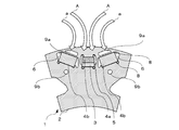
- FIG. 13 A second embodiment of the present invention will be described with reference to FIG.
- the fixed magnetic magnets 4b and 4b are arranged on both sides of the variable magnetic magnet 3 to constitute the first magnetic pole of the rotor.
- a fixed magnetic force magnet 4a is disposed adjacent to the first magnetic pole to constitute a second magnetic pole.
- the polarities of the fixed magnetic magnets 4a and 4b in the adjacent first and second magnetic poles are arranged to have different polarities on the outer peripheral side and the inner peripheral side of the rotor.
- a first magnetic pole in which fixed magnetic magnets 4b and 4b are arranged on both sides of the variable magnetic magnet 3, and a fixed magnetic magnet 4b and 4b of the first magnetic pole arranged on both sides of the first magnetic pole.
- the magnetic poles of the rotor are formed from the second magnetic poles configured by using the fixed magnetic force magnets 4a having different values.
- the variable magnetic magnet 3 and the fixed magnetic magnets 4b and 4b are arranged in parallel on the magnetic circuit, and the fixed magnetic force arranged on the variable magnetic magnet 3 of the first magnetic pole and the second magnetic pole.
- the magnet 4a is arrange
- the variable magnetic force magnet 3 is not arranged in series with the fixed magnetic force magnet in one pole of the rotor.
- the variable magnetic magnet 3 is arranged in series with the fixed magnetic magnet 4a of the adjacent pole, and is affected by the magnetic field of the fixed magnetic magnet 4a. Therefore, the fixed magnetic magnet 3 as in the first embodiment is used. The same effect as when 4a is laminated can be obtained. That is, the magnetic field of the fixed magnetic magnet 4 a at the pole of the adjacent rotor is opposite to the magnetic field of the fixed magnetic magnets 4 b and 4 b arranged in parallel to the variable magnetic magnet 3 inside the variable magnetic magnet 3. , Act to offset each other.
- variable magnetic force magnet 3 when the variable magnetic force magnet 3 is magnetized from the irreversible demagnetized state and returned to the original polarity, the magnetic field by the adjacent fixed magnetic force magnets 4b and 4b that hinder the change can be reduced.
- the magnetizing current (d-axis current) required when changing the magnetic force 3 can be reduced.
- the single magnetized magnet 4 b is positioned at the position where the magnetization direction is the d-axis direction (here, substantially the radial direction of the rotor) (the center portion of the stator core).
- the rotor core 2 a series of magnets formed by stacking the variable magnetic force magnet 3 and the fixed magnetic force magnet 4a in series is arranged on both sides of the fixed magnetic force magnet 4b at a position where the magnetization direction is the d-axis direction.
- the magnet series in which the variable magnetic magnets 3 and the fixed magnetic magnets 4a arranged on both sides are stacked constitutes a parallel circuit on the magnetic circuit with respect to the fixed magnetic magnet 4b at the magnetic pole center.
- the cavity 6 is formed at the end of the variable magnetic magnet 3 and the fixed magnetic magnet 4a so that the magnetic flux passing through the rotor core 2 passes through the portions of the variable magnetic magnet 3 and the fixed magnetic magnet 4a in the thickness direction.
- a magnet series in which the variable magnetic magnet 3 and the fixed magnetic magnet 4a are stacked on the left and right with respect to the magnetic pole is provided. Since they are arranged, the variable magnetic magnet 3 can be magnetized by dividing the left and right sides twice. As a result, there is only one fixed magnetic magnet 4b arranged in parallel that will prevent the polarity change of the variable magnetic magnet 3. That is, as compared with the first embodiment in which two fixed magnetic magnets 4b are arranged, the magnetic field by the fixed magnetic magnet 4b that prevents the change in polarity of the variable magnetic magnet 3 can be reduced, so that the magnetic force of the variable magnetic magnet 3 is changed.
- the magnetizing current (d-axis current) required for the generation can be reduced.
- the permanent magnet In the permanent magnet forming the magnetic pole, the permanent magnet is defined to be distinguished by the product of the coercive force and the thickness in the magnetization direction. Therefore, even if the magnetic pole is formed of a permanent magnet made of the same material and is formed so as to have different thicknesses in the magnetization direction, the same operation and effect can be obtained.
- the permanent magnet was magnetized by a magnetic field generated by a pulse-like d-axis current for a very short time during operation to irreversibly change the amount of magnetic flux of the permanent magnet, and the phase was advanced with respect to the induced voltage of all the magnets.
- the amount of interlinkage magnetic flux of the armature winding generated by the current and the permanent magnet is changed.
Landscapes
- Engineering & Computer Science (AREA)
- Power Engineering (AREA)
- Permanent Field Magnets Of Synchronous Machinery (AREA)
- Permanent Magnet Type Synchronous Machine (AREA)
Priority Applications (3)
| Application Number | Priority Date | Filing Date | Title |
|---|---|---|---|
| EP09827357.6A EP2360814B1 (en) | 2008-11-19 | 2009-11-19 | Permanent magnet type rotating electric machine |
| CN2009801460067A CN102217170B (zh) | 2008-11-19 | 2009-11-19 | 永久磁铁式旋转电机 |
| US13/130,206 US8624457B2 (en) | 2008-11-19 | 2009-11-19 | Permanent magnet electric motor |
Applications Claiming Priority (2)
| Application Number | Priority Date | Filing Date | Title |
|---|---|---|---|
| JP2008296080A JP5159577B2 (ja) | 2008-11-19 | 2008-11-19 | 永久磁石式回転電機 |
| JP2008-296080 | 2008-11-19 |
Publications (1)
| Publication Number | Publication Date |
|---|---|
| WO2010058576A1 true WO2010058576A1 (ja) | 2010-05-27 |
Family
ID=42198019
Family Applications (1)
| Application Number | Title | Priority Date | Filing Date |
|---|---|---|---|
| PCT/JP2009/006216 WO2010058576A1 (ja) | 2008-11-19 | 2009-11-19 | 永久磁石式回転電機 |
Country Status (5)
| Country | Link |
|---|---|
| US (1) | US8624457B2 (zh) |
| EP (1) | EP2360814B1 (zh) |
| JP (1) | JP5159577B2 (zh) |
| CN (1) | CN102217170B (zh) |
| WO (1) | WO2010058576A1 (zh) |
Cited By (2)
| Publication number | Priority date | Publication date | Assignee | Title |
|---|---|---|---|---|
| WO2012042446A2 (en) | 2010-09-27 | 2012-04-05 | Promogreen.Com.S.R.L. | Fibres and relative woven and non woven tissues for the topic treatment of sexual dysfunctions of the male genital apparatus |
| EP2595281A4 (en) * | 2010-07-14 | 2016-09-21 | Toyota Jidoshokki Kk | PERMANENT RECESSING MAGNET ROTARY ELEMENT AND ROTATING ELECTRIC MACHINE |
Families Citing this family (51)
| Publication number | Priority date | Publication date | Assignee | Title |
|---|---|---|---|---|
| EP2048772B1 (en) | 2006-07-24 | 2021-10-20 | Kabushiki Kaisha Toshiba | Variable magnetic flux motor drive system |
| JP5502571B2 (ja) * | 2010-04-09 | 2014-05-28 | 株式会社東芝 | 永久磁石式回転電機 |
| US20130127280A1 (en) * | 2010-07-30 | 2013-05-23 | Hitachi, Ltd. | Electric rotating machine and electric vehicle using the same |
| DE112010005803B4 (de) * | 2010-08-11 | 2015-08-27 | Toyota Jidosha Kabushiki Kaisha | Koerzitivitäts-Bestimmungsvorrichtung für Magnete mit verteilter Koerzitivität |
| CN101969242A (zh) * | 2010-09-21 | 2011-02-09 | 哈尔滨工业大学 | 永磁流体处理器 |
| JP5186036B2 (ja) * | 2011-03-31 | 2013-04-17 | 日新製鋼株式会社 | Ipmモータの回転子及びそれを用いたipmモータ |
| JP5372296B2 (ja) * | 2011-05-16 | 2013-12-18 | 三菱電機株式会社 | 永久磁石型回転電機 |
| JP5787673B2 (ja) * | 2011-08-30 | 2015-09-30 | 株式会社東芝 | 永久磁石型回転電機 |
| US8941970B2 (en) * | 2011-10-18 | 2015-01-27 | Siemens Energy, Inc. | Method and apparatus for demagnetizing generator components prior to electromagnetic core imperfection testing or EL-CID testing |
| WO2013094075A1 (ja) * | 2011-12-23 | 2013-06-27 | 三菱電機株式会社 | 永久磁石型モータ |
| EP2611002A3 (en) * | 2011-12-28 | 2015-07-08 | Remy Technologies, LLC | Dual magnet rotor |
| DE102012020927A1 (de) | 2012-03-13 | 2013-09-19 | Brose Fahrzeugteile GmbH & Co. Kommanditgesellschaft, Würzburg | Elektrische Maschine |
| EP2839567A4 (en) * | 2012-04-16 | 2016-05-11 | Otis Elevator Co | ELECTRIC MACHINE WITH PERMANENT MAGNETS |
| CN104247214B (zh) * | 2012-04-23 | 2017-05-24 | 三菱电机株式会社 | 永磁体型旋转电机及车辆驱动系统 |
| JP5977155B2 (ja) * | 2012-11-26 | 2016-08-24 | アイチエレック株式会社 | 永久磁石電動機 |
| KR101407854B1 (ko) * | 2012-12-03 | 2014-06-16 | 뉴모텍(주) | 가변 자속 모터 |
| EP2941818B1 (en) * | 2013-01-02 | 2022-03-23 | Trane International Inc. | System and method for diagnosing magnet degradation and damage for permanent magnet motors |
| JP6090987B2 (ja) * | 2013-02-21 | 2017-03-08 | 本田技研工業株式会社 | 回転電機 |
| US20140265751A1 (en) * | 2013-03-15 | 2014-09-18 | Flux Energy Systems, Llc | Electric motor |
| CN103219852A (zh) * | 2013-04-18 | 2013-07-24 | 台州市金宇机电有限公司 | 内置式低速大转矩永磁轮毂电机 |
| CN103236762B (zh) * | 2013-04-18 | 2015-08-19 | 台州市金宇机电有限公司 | 电动车用无刷直流轮毂电机及其控制系统 |
| CN103208897B (zh) * | 2013-04-27 | 2016-03-23 | 佛山市顺德区苇源电器有限公司 | 无刷直流电机 |
| CN103441592A (zh) * | 2013-08-12 | 2013-12-11 | 浙江大学 | 新型磁通可调永磁同步电机 |
| FR3016251B1 (fr) | 2014-01-09 | 2017-12-15 | Leroy Somer Moteurs | Machine electrique a aimants permanents inseres a force |
| JP6517469B2 (ja) * | 2014-02-25 | 2019-05-22 | 東芝インフラシステムズ株式会社 | 永久磁石回転電機システム |
| CN105680657A (zh) * | 2014-12-03 | 2016-06-15 | 通用电气公司 | 无传感器电机 |
| KR20160116568A (ko) * | 2015-03-30 | 2016-10-10 | 현대자동차주식회사 | 절연부재를 갖는 모터유닛 |
| JP6451990B2 (ja) * | 2015-04-02 | 2019-01-16 | 株式会社デンソー | 回転電機 |
| CN106154045B (zh) * | 2015-04-14 | 2018-10-02 | 维谛技术有限公司 | 一种电网阻抗的测量方法和装置 |
| WO2016179841A1 (zh) * | 2015-05-14 | 2016-11-17 | 广东美芝制冷设备有限公司 | 旋转电机的转子、永磁电动机、压缩机、空调系统 |
| US11011965B2 (en) | 2015-07-31 | 2021-05-18 | Nissan Motor Co., Ltd. | Permanent magnet synchronous motor |
| JP6577831B2 (ja) * | 2015-10-28 | 2019-09-18 | 株式会社エクセディ | 回転電機 |
| US10193421B2 (en) * | 2015-11-13 | 2019-01-29 | General Electric Company | System for thermal management in electrical machines |
| KR101762270B1 (ko) * | 2016-02-15 | 2017-07-31 | 한국생산기술연구원 | 가변자속자기회로의 제어특성을 고려한 마그넷 배열 |
| KR102629775B1 (ko) * | 2016-04-12 | 2024-01-26 | 삼성전자주식회사 | 매입형 영구자석 모터 |
| CN110011442B (zh) * | 2016-06-30 | 2022-02-11 | 广东美芝制冷设备有限公司 | 电动机转子和具有其的电动机、压缩机 |
| KR102572084B1 (ko) | 2017-07-27 | 2023-08-30 | 삼성전자주식회사 | 모터 및 모터의 제어 방법, 모터를 구비한 세탁기 |
| US11018567B2 (en) * | 2017-09-29 | 2021-05-25 | Ford Global Technologies, Llc | Permanent magnet rotor with enhanced demagnetization protection |
| CN108023421B (zh) * | 2017-12-21 | 2024-05-28 | 珠海格力电器股份有限公司 | 电机转子和永磁电机 |
| US11450463B2 (en) | 2018-02-02 | 2022-09-20 | Robotiq Inc. | Programmable permanent magnet actuator and a magnetic field generation apparatus and method |
| DE102018206478A1 (de) | 2018-04-26 | 2019-10-31 | Robert Bosch Gmbh | Elektrische Maschine mit veränderlichem magnetischem Fluss |
| JP6713026B2 (ja) * | 2018-10-03 | 2020-06-24 | Dmg森精機株式会社 | ロータ |
| US10797546B2 (en) * | 2019-01-08 | 2020-10-06 | Borgwarner Inc. | Interior permanent magnet electric machine with flux distributing voids |
| CN110034623A (zh) * | 2019-05-20 | 2019-07-19 | 珠海格力节能环保制冷技术研究中心有限公司 | 电机转子、电机及机械结构 |
| CN110034624A (zh) * | 2019-05-20 | 2019-07-19 | 珠海格力节能环保制冷技术研究中心有限公司 | 电机转子、电机及机械结构 |
| WO2021076428A1 (en) * | 2019-10-15 | 2021-04-22 | Darrell Schmidt Enterprises, Inc. | Magnetic coupler |
| CN110739821B (zh) * | 2019-11-06 | 2024-04-30 | 天津工业大学 | 电动汽车用低铁耗可变磁通永磁记忆电机稳健性设计方法 |
| CN110838780B (zh) * | 2019-11-26 | 2021-05-25 | 江苏大学 | 一种交直轴磁阻可控式永磁无刷电机 |
| US11462960B2 (en) * | 2019-12-02 | 2022-10-04 | Hiwin Mikrosystem Corp. | Rotor with first and second permanent magnets having support members and slots |
| CN111769667B (zh) * | 2020-06-30 | 2023-02-28 | 东南大学 | 串并联磁路分置磁极型记忆电机 |
| US11791676B2 (en) * | 2020-07-02 | 2023-10-17 | Hl Mando Corporation | Electric motor having rotor assembly with segmented permanent magnet |
Citations (5)
| Publication number | Priority date | Publication date | Assignee | Title |
|---|---|---|---|---|
| JP2002252939A (ja) * | 2002-01-17 | 2002-09-06 | Toshiba Corp | 永久磁石式リラクタンス型回転電機 |
| JP2006280195A (ja) | 2005-03-01 | 2006-10-12 | Toshiba Corp | 永久磁石式回転電機 |
| WO2008013167A1 (fr) * | 2006-07-24 | 2008-01-31 | Kabushiki Kaisha Toshiba | Système d'entraînement de moteur à flux magnétique variable |
| JP2008048514A (ja) | 2006-08-11 | 2008-02-28 | Toshiba Corp | 永久磁石式回転電機の回転子 |
| JP2008245368A (ja) * | 2007-03-26 | 2008-10-09 | Toshiba Corp | 永久磁石式回転電機及び永久磁石電動機ドライブシステム |
Family Cites Families (16)
| Publication number | Priority date | Publication date | Assignee | Title |
|---|---|---|---|---|
| US4939398A (en) * | 1986-10-06 | 1990-07-03 | Emerson Electric Co. | Laminated assemblies with in situ molded magnets |
| FR2762722B1 (fr) * | 1997-04-23 | 1999-07-30 | Centre Nat Rech Scient | Machine electrique a double excitation perfectionnee |
| JP3818340B2 (ja) * | 1997-09-26 | 2006-09-06 | 株式会社富士通ゼネラル | 永久磁石電動機 |
| US6800977B1 (en) | 1997-12-23 | 2004-10-05 | Ford Global Technologies, Llc. | Field control in permanent magnet machine |
| JP2002078259A (ja) * | 2000-08-31 | 2002-03-15 | Yamaha Motor Co Ltd | 永久磁石回転子 |
| WO2003079516A1 (fr) * | 2002-03-20 | 2003-09-25 | Daikin Industries, Ltd. | Moteur de type a aimants permanents et compresseur dote de ce moteur |
| US7067948B2 (en) * | 2002-10-18 | 2006-06-27 | Mitsubishi Denki Kabushiki Kaisha | Permanent-magnet rotating machine |
| US7504754B2 (en) * | 2005-10-31 | 2009-03-17 | Caterpillar Inc. | Rotor having multiple permanent-magnet pieces in a cavity |
| US20070159021A1 (en) * | 2005-12-19 | 2007-07-12 | Emerson Electric Co. | Composite magnet structure for rotor |
| JP2007300787A (ja) * | 2006-04-27 | 2007-11-15 | Sun Tech Generator Co Ltd | 発電機・電動機用回転子 |
| US20070284960A1 (en) * | 2006-06-12 | 2007-12-13 | Remy International, Inc. | Magnet for a dynamoelectric machine, dynamoelectric machine and method |
| EP2061132B1 (en) | 2006-08-23 | 2023-07-19 | Kabushiki Kaisha Toshiba | Permanent magnetic type electric motor |
| US7598645B2 (en) * | 2007-05-09 | 2009-10-06 | Uqm Technologies, Inc. | Stress distributing permanent magnet rotor geometry for electric machines |
| US8860356B2 (en) | 2007-09-18 | 2014-10-14 | Kabushiki Kaisha Toshiba | Variable magnetic flux motor drive system |
| JP2009201259A (ja) | 2008-02-21 | 2009-09-03 | Toshiba Corp | 永久磁石式回転電機、永久磁石式回転電機の組立方法、永久磁石式回転電機の分解方法及び永久磁石電動機ドライブシステム |
| JP5161612B2 (ja) | 2008-02-22 | 2013-03-13 | 株式会社東芝 | 永久磁石式回転電機、永久磁石式回転電機の組立方法及び永久磁石式回転電機の分解方法 |
-
2008
- 2008-11-19 JP JP2008296080A patent/JP5159577B2/ja active Active
-
2009
- 2009-11-19 WO PCT/JP2009/006216 patent/WO2010058576A1/ja active Application Filing
- 2009-11-19 US US13/130,206 patent/US8624457B2/en active Active
- 2009-11-19 EP EP09827357.6A patent/EP2360814B1/en active Active
- 2009-11-19 CN CN2009801460067A patent/CN102217170B/zh active Active
Patent Citations (5)
| Publication number | Priority date | Publication date | Assignee | Title |
|---|---|---|---|---|
| JP2002252939A (ja) * | 2002-01-17 | 2002-09-06 | Toshiba Corp | 永久磁石式リラクタンス型回転電機 |
| JP2006280195A (ja) | 2005-03-01 | 2006-10-12 | Toshiba Corp | 永久磁石式回転電機 |
| WO2008013167A1 (fr) * | 2006-07-24 | 2008-01-31 | Kabushiki Kaisha Toshiba | Système d'entraînement de moteur à flux magnétique variable |
| JP2008048514A (ja) | 2006-08-11 | 2008-02-28 | Toshiba Corp | 永久磁石式回転電機の回転子 |
| JP2008245368A (ja) * | 2007-03-26 | 2008-10-09 | Toshiba Corp | 永久磁石式回転電機及び永久磁石電動機ドライブシステム |
Non-Patent Citations (2)
| Title |
|---|
| See also references of EP2360814A4 |
| YOJI TAKEDA ET AL.: "Design and control of embedded magnet synchronous motor", October 2001, OHMSHA, LTD. |
Cited By (2)
| Publication number | Priority date | Publication date | Assignee | Title |
|---|---|---|---|---|
| EP2595281A4 (en) * | 2010-07-14 | 2016-09-21 | Toyota Jidoshokki Kk | PERMANENT RECESSING MAGNET ROTARY ELEMENT AND ROTATING ELECTRIC MACHINE |
| WO2012042446A2 (en) | 2010-09-27 | 2012-04-05 | Promogreen.Com.S.R.L. | Fibres and relative woven and non woven tissues for the topic treatment of sexual dysfunctions of the male genital apparatus |
Also Published As
| Publication number | Publication date |
|---|---|
| US20120091848A1 (en) | 2012-04-19 |
| US8624457B2 (en) | 2014-01-07 |
| CN102217170B (zh) | 2013-11-13 |
| JP2010124608A (ja) | 2010-06-03 |
| EP2360814A4 (en) | 2018-01-31 |
| EP2360814A1 (en) | 2011-08-24 |
| CN102217170A (zh) | 2011-10-12 |
| EP2360814B1 (en) | 2018-10-03 |
| JP5159577B2 (ja) | 2013-03-06 |
Similar Documents
| Publication | Publication Date | Title |
|---|---|---|
| JP5159577B2 (ja) | 永久磁石式回転電機 | |
| JP5361261B2 (ja) | 永久磁石式回転電機 | |
| JP5305753B2 (ja) | 永久磁石式回転電機 | |
| JP5085071B2 (ja) | 永久磁石式回転電機の回転子 | |
| JP5361260B2 (ja) | 永久磁石回転式電機 | |
| JP5355055B2 (ja) | 永久磁石式回転電機 | |
| JP5398103B2 (ja) | 永久磁石式回転電機 | |
| JP5787673B2 (ja) | 永久磁石型回転電機 | |
| JP5159171B2 (ja) | 永久磁石式回転電機 | |
| JP2010148235A (ja) | 永久磁石式回転電機 | |
| JP7076188B2 (ja) | 可変磁力モータ | |
| JP5178488B2 (ja) | 永久磁石式回転電機 | |
| JP5198178B2 (ja) | 永久磁石式回転電機及び永久磁石電動機ドライブシステム | |
| JP2012175738A (ja) | 永久磁石式回転電機 | |
| JP2019154232A (ja) | 回転子および回転電機 | |
| JP5446476B2 (ja) | 埋込磁石型同期電動機のロータ | |
| JP4735772B1 (ja) | 磁石励磁回転電機システム | |
| JP2012029563A (ja) | 永久磁石式回転電機 | |
| JP2013051760A (ja) | 永久磁石式回転電機 | |
| JP2011172323A (ja) | 永久磁石式回転電機 | |
| JP5197551B2 (ja) | 永久磁石式回転電機 | |
| JP5390314B2 (ja) | 永久磁石式回転電機 | |
| JP5178487B2 (ja) | 永久磁石式回転電機 |
Legal Events
| Date | Code | Title | Description |
|---|---|---|---|
| WWE | Wipo information: entry into national phase |
Ref document number: 200980146006.7 Country of ref document: CN |
|
| 121 | Ep: the epo has been informed by wipo that ep was designated in this application |
Ref document number: 09827357 Country of ref document: EP Kind code of ref document: A1 |
|
| NENP | Non-entry into the national phase |
Ref country code: DE |
|
| WWE | Wipo information: entry into national phase |
Ref document number: 2009827357 Country of ref document: EP |
|
| WWE | Wipo information: entry into national phase |
Ref document number: 13130206 Country of ref document: US |