WO2010050569A1 - 高圧燃料供給ポンプ - Google Patents
高圧燃料供給ポンプ Download PDFInfo
- Publication number
- WO2010050569A1 WO2010050569A1 PCT/JP2009/068617 JP2009068617W WO2010050569A1 WO 2010050569 A1 WO2010050569 A1 WO 2010050569A1 JP 2009068617 W JP2009068617 W JP 2009068617W WO 2010050569 A1 WO2010050569 A1 WO 2010050569A1
- Authority
- WO
- WIPO (PCT)
- Prior art keywords
- cylinder
- plunger
- pressurizing chamber
- pump housing
- pump
- Prior art date
- Legal status (The legal status is an assumption and is not a legal conclusion. Google has not performed a legal analysis and makes no representation as to the accuracy of the status listed.)
- Ceased
Links
Images


Classifications
-
- F—MECHANICAL ENGINEERING; LIGHTING; HEATING; WEAPONS; BLASTING
- F02—COMBUSTION ENGINES; HOT-GAS OR COMBUSTION-PRODUCT ENGINE PLANTS
- F02M—SUPPLYING COMBUSTION ENGINES IN GENERAL WITH COMBUSTIBLE MIXTURES OR CONSTITUENTS THEREOF
- F02M59/00—Pumps specially adapted for fuel-injection and not provided for in groups F02M39/00 -F02M57/00, e.g. rotary cylinder-block type of pumps
- F02M59/44—Details, components parts, or accessories not provided for in, or of interest apart from, the apparatus of groups F02M59/02 - F02M59/42; Pumps having transducers, e.g. to measure displacement of pump rack or piston
-
- F—MECHANICAL ENGINEERING; LIGHTING; HEATING; WEAPONS; BLASTING
- F02—COMBUSTION ENGINES; HOT-GAS OR COMBUSTION-PRODUCT ENGINE PLANTS
- F02M—SUPPLYING COMBUSTION ENGINES IN GENERAL WITH COMBUSTIBLE MIXTURES OR CONSTITUENTS THEREOF
- F02M39/00—Arrangements of fuel-injection apparatus with respect to engines; Pump drives adapted to such arrangements
- F02M39/02—Arrangements of fuel-injection apparatus to facilitate the driving of pumps; Arrangements of fuel-injection pumps; Pump drives
-
- F—MECHANICAL ENGINEERING; LIGHTING; HEATING; WEAPONS; BLASTING
- F04—POSITIVE - DISPLACEMENT MACHINES FOR LIQUIDS; PUMPS FOR LIQUIDS OR ELASTIC FLUIDS
- F04B—POSITIVE-DISPLACEMENT MACHINES FOR LIQUIDS; PUMPS
- F04B1/00—Multi-cylinder machines or pumps characterised by number or arrangement of cylinders
- F04B1/04—Multi-cylinder machines or pumps characterised by number or arrangement of cylinders having cylinders in star- or fan-arrangement
- F04B1/0404—Details or component parts
- F04B1/0408—Pistons
-
- F—MECHANICAL ENGINEERING; LIGHTING; HEATING; WEAPONS; BLASTING
- F04—POSITIVE - DISPLACEMENT MACHINES FOR LIQUIDS; PUMPS FOR LIQUIDS OR ELASTIC FLUIDS
- F04B—POSITIVE-DISPLACEMENT MACHINES FOR LIQUIDS; PUMPS
- F04B1/00—Multi-cylinder machines or pumps characterised by number or arrangement of cylinders
- F04B1/04—Multi-cylinder machines or pumps characterised by number or arrangement of cylinders having cylinders in star- or fan-arrangement
- F04B1/0404—Details or component parts
- F04B1/0421—Cylinders
-
- F—MECHANICAL ENGINEERING; LIGHTING; HEATING; WEAPONS; BLASTING
- F04—POSITIVE - DISPLACEMENT MACHINES FOR LIQUIDS; PUMPS FOR LIQUIDS OR ELASTIC FLUIDS
- F04B—POSITIVE-DISPLACEMENT MACHINES FOR LIQUIDS; PUMPS
- F04B1/00—Multi-cylinder machines or pumps characterised by number or arrangement of cylinders
- F04B1/04—Multi-cylinder machines or pumps characterised by number or arrangement of cylinders having cylinders in star- or fan-arrangement
- F04B1/0404—Details or component parts
- F04B1/0439—Supporting or guiding means for the pistons
-
- F—MECHANICAL ENGINEERING; LIGHTING; HEATING; WEAPONS; BLASTING
- F04—POSITIVE - DISPLACEMENT MACHINES FOR LIQUIDS; PUMPS FOR LIQUIDS OR ELASTIC FLUIDS
- F04B—POSITIVE-DISPLACEMENT MACHINES FOR LIQUIDS; PUMPS
- F04B53/00—Component parts, details or accessories not provided for in, or of interest apart from, groups F04B1/00 - F04B23/00 or F04B39/00 - F04B47/00
- F04B53/16—Casings; Cylinders; Cylinder liners or heads; Fluid connections
- F04B53/162—Adaptations of cylinders
- F04B53/166—Cylinder liners
- F04B53/168—Mounting of cylinder liners in cylinders
-
- F—MECHANICAL ENGINEERING; LIGHTING; HEATING; WEAPONS; BLASTING
- F02—COMBUSTION ENGINES; HOT-GAS OR COMBUSTION-PRODUCT ENGINE PLANTS
- F02M—SUPPLYING COMBUSTION ENGINES IN GENERAL WITH COMBUSTIBLE MIXTURES OR CONSTITUENTS THEREOF
- F02M2200/00—Details of fuel-injection apparatus, not otherwise provided for
- F02M2200/02—Fuel-injection apparatus having means for reducing wear
-
- F—MECHANICAL ENGINEERING; LIGHTING; HEATING; WEAPONS; BLASTING
- F02—COMBUSTION ENGINES; HOT-GAS OR COMBUSTION-PRODUCT ENGINE PLANTS
- F02M—SUPPLYING COMBUSTION ENGINES IN GENERAL WITH COMBUSTIBLE MIXTURES OR CONSTITUENTS THEREOF
- F02M2200/00—Details of fuel-injection apparatus, not otherwise provided for
- F02M2200/85—Mounting of fuel injection apparatus
-
- F—MECHANICAL ENGINEERING; LIGHTING; HEATING; WEAPONS; BLASTING
- F02—COMBUSTION ENGINES; HOT-GAS OR COMBUSTION-PRODUCT ENGINE PLANTS
- F02M—SUPPLYING COMBUSTION ENGINES IN GENERAL WITH COMBUSTIBLE MIXTURES OR CONSTITUENTS THEREOF
- F02M59/00—Pumps specially adapted for fuel-injection and not provided for in groups F02M39/00 -F02M57/00, e.g. rotary cylinder-block type of pumps
- F02M59/02—Pumps specially adapted for fuel-injection and not provided for in groups F02M39/00 -F02M57/00, e.g. rotary cylinder-block type of pumps of reciprocating-piston or reciprocating-cylinder type
- F02M59/10—Pumps specially adapted for fuel-injection and not provided for in groups F02M39/00 -F02M57/00, e.g. rotary cylinder-block type of pumps of reciprocating-piston or reciprocating-cylinder type characterised by the piston-drive
- F02M59/102—Mechanical drive, e.g. tappets or cams
-
- F—MECHANICAL ENGINEERING; LIGHTING; HEATING; WEAPONS; BLASTING
- F02—COMBUSTION ENGINES; HOT-GAS OR COMBUSTION-PRODUCT ENGINE PLANTS
- F02M—SUPPLYING COMBUSTION ENGINES IN GENERAL WITH COMBUSTIBLE MIXTURES OR CONSTITUENTS THEREOF
- F02M59/00—Pumps specially adapted for fuel-injection and not provided for in groups F02M39/00 -F02M57/00, e.g. rotary cylinder-block type of pumps
- F02M59/20—Varying fuel delivery in quantity or timing
- F02M59/36—Varying fuel delivery in quantity or timing by variably-timed valves controlling fuel passages to pumping elements or overflow passages
- F02M59/366—Valves being actuated electrically
Definitions
- the present invention relates to a high-pressure fuel supply pump for an internal combustion engine assembled to an engine block of the internal combustion engine, and more particularly to an assembly mechanism thereof.
- a holder (46) having an outer cylindrical surface portion that fits into a mounting hole (48) formed in the engine is disclosed.
- a plunger seal member is held on the inner cylindrical surface portion of the holder (46).
- the outer cylindrical surface portion and the inner cylindrical surface portion can be processed from a single member, so that the centers of the outer cylindrical surface portion and the inner cylindrical surface portion can be processed coaxially.
- the center axis of the cylinder (guide area: 32) fitted into the pump housing (28) and the center axis of the plunger (piston: 40) inserted through the cylinder (guide area: 32) are the center of the holder (46). There is no guarantee that it will be assembled coaxially with the axis.
- An object of the present invention is to enable a cylinder of a high-pressure fuel supply pump to be accurately positioned with respect to an attachment fitting hole provided in the engine block when the high-pressure fuel supply pump is attached to an engine block of an internal combustion engine.
- an outer cylindrical surface portion that fits into a high pressure fuel pump mounting fitting hole provided in an engine block of an internal combustion engine, and a cylindrical fitting portion that fits on the outer periphery of a cylinder of the high pressure fuel pump.
- a holder provided is provided, and this holder achieves the above-mentioned object by configuring the outer cylindrical surface part and the cylindrical fitting part as one part obtained by processing the same member.
- the configuration as described above allows the central axis of the piston plunger insertion hole provided in the cylinder to be the central axis of the mounting fitting hole provided in the engine block of the internal combustion engine. Coaxiality can be easily obtained, and the biting and wear of the cylinder and the piston plunger due to the side force applied to the plunger by the drive mechanism can be reduced.
- 1 is an example of a fuel supply system using a high-pressure fuel supply pump according to a first embodiment in which the present invention is implemented.
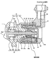
- 1 is a longitudinal sectional view of a high-pressure fuel supply pump according to a first embodiment in which the present invention is implemented. It is a longitudinal cross-sectional view of another angle of the high-pressure fuel supply pump by the 1st Example by which this invention was implemented, and represents the longitudinal cross-section of the position which shifted
- FIG. 1 shows a method of assembling a piston plunger unit of a high-pressure fuel supply pump according to a first embodiment in which the present invention is implemented.
- the external view of the flange of a high-pressure fuel supply pump by the 1st Example by which this invention was implemented, and a bush is shown. In the figure, only the flange and the bush are shown, and other parts are not shown.
- the enlarged view near the welding part of the attachment flange of the high-pressure fuel supply pump and pump main body by 1st Example by which this invention was implemented is shown.
- FIG. 12 is an enlarged view of the vicinity of the welded portion between the mounting flange of the high-pressure fuel supply pump and the pump body according to the first embodiment in which the present invention is implemented, and is a drawing further enlarged than FIG. 11.
- the basic configuration of the embodiment in which the present invention is implemented is as described below.
- the internal code indicates the code of the relevant part of the embodiment for reference.
- the pump housing (1) has a bottomed recess (1A) at the center.
- a cylindrical cylinder (6) is combined with the inner peripheral cylindrical portion on the open end side of the recess (1A) to partition the recess (1A) as a pressurizing chamber (11).
- Fuel is sucked into the pressurizing chamber (11) by the reciprocating motion of the piston plunger (2) that slides on the cylinder (6) and pressurizes the fluid in the pressurizing chamber (11), and is added in the pressurizing chamber (11).
- the pressurized fuel is discharged from the discharge port (12) through the discharge valve unit (8).
- the cylinder holder (7) has an outer cylindrical surface portion (7b) that fits into the mounting fitting hole (101) of the engine block (100) of the internal combustion engine, and the cylinder holder (7) is a cylinder (6).
- the outer cylindrical surface portion (7b) and the cylindrical fitting portion (7a) are configured as one part obtained by processing the same member.
- the mounting fitting hole (70) provided in the engine block (100) functions as a positioning cylindrical portion between the outer periphery of the cylinder holder (7).
- the central axis of the insertion hole of the piston plunger (2) provided in the cylinder (6) is coaxial with the central axis of the mounting fitting hole (70) provided in the engine block (100) of the internal combustion engine. It is easy to be done. As a result, wear due to engagement and sliding between the cylinder (6) and the piston plunger (2) due to the side force applied to the piston plunger (2) by the drive mechanism can be reduced.
- the outer cylindrical surface portion (7b) and the cylindrical fitting portion (7a) are cylindrical surfaces whose axial centers coincide with the central axis of the insertion hole of the piston plunger (2) formed in the cylinder (6). It is configured.
- the cylinder (6) is in pressure contact with the pump housing (1), and forms a seal portion (6a) by metal contact in this pressure contact portion, thus defining the pressurizing chamber (11) and the cylinder.
- the holder (7) is configured to function as a fixing means that presses the cylinder (6) and the pump housing (1). A pressing force in the circumferential direction by press-fitting can be used as the fixing means for press contact. Also, caulking can be used.
- a second seal member that forms a seal portion on the outer cylindrical surface portion (7b) of the cylinder holder (7) in cooperation with the inner peripheral surface of the attachment fitting hole (70) of the engine block (100). (62) is attached. Sealing of each part can be achieved while aligning the shaft center.
- the piston plunger (2) includes a seal member (13) mounted on the outer peripheral surface opposite to the pressurizing chamber (11), and the cylinder holder (7) stores the seal member (13).
- An inner cylindrical surface portion (7c) is provided. According to this configuration, the axial centers of the piston plunger seal member (13) and the piston plunger (2) can be accurately aligned.
- the outer cylindrical surface portion (7b), the inner cylindrical surface portion (7c), and the cylindrical fitting portion (7a) are configured as one component obtained by processing the same member. According to this configuration, the three axes can be accurately aligned.
- the outer cylindrical surface portion (7b), the inner cylindrical surface portion (7c), and the cylindrical fitting portion (7a) are configured to have the same axis. According to this configuration, the three axes can be accurately aligned.
- an adjustment gap (1B) is provided between the inner peripheral surface of the pump housing (1) defining the pressurizing chamber (11) and the outer peripheral surface of the cylinder (6) protruding into the pressurizing chamber (11). It is provided. According to this configuration, even if the pump housing (1) expands inward due to heat, the deformation of the pump housing is absorbed by this gap, so that no side force acts on the central piston plunger (2). The cylinder does not deform inward due to the reaction force expanding outward.
- a third seal member (62) is provided in the outer peripheral groove (7f) of the cylinder holder (7) between the outer peripheral surface of the cylinder holder (7) and the pump housing (1).
- a seal between the cylinder holder (7) and the pump housing (1) can be achieved.
- the metal contact portion of the pump housing (1) and the cylinder (6) constitutes a seal portion (6a) by metal contact, thereby defining the pressurizing chamber (11) and the cylinder (6).
- the leakage of fuel from the piston plunger and the field is sealed by a seal member (13) mounted on the outer periphery of the piston plunger (2) extending outward from the sliding portion of the cylinder (6) and the piston plunger (2).
- This seal member (13) is fixed to the inner cylindrical surface portion (7c) of the cylinder holder (7). According to this configuration, the plunger seal holder and the cylinder holder can be shared.
- the piston plunger (2) is configured to be able to advance and retreat into the pressurizing chamber formed in the pump housing (1) beyond the tip of the cylinder (6).
- the piston plunger (2) protruding into the pressurizing chamber (11) is cooled by the fuel in the pressurizing chamber, sliding wear at the sliding hole of the cylinder (6) can be reduced.
- the sliding part of the cylinder (6) and the piston plunger (2) can be brought close to the axial center part of the piston plunger (2), and the tilt of the piston plunger (2) can be suppressed.
- the metal contact seal portion (6a) is formed by press-contacting the pump housing (1) and the cylinder (6) with a surface intersecting the moving direction of the piston plunger (2).
- the press mechanism (a cylinder holder (7) in an Example) which presses a pump housing (1) and a cylinder (6) relatively toward a metal contact seal part (6a) is provided.
- the force for sealing can be increased, and sealing is ensured.
- the pressing mechanism the lower end of the cylinder can be crimped toward the sealing surface.
- the pressing mechanism (cylinder holder (7) in the embodiment) has a threaded portion (7g) formed on the outer periphery of the cylinder holder (7) and a second housing formed on the pump housing 1 screwed to the screw portion (7g). It consists of a screw part (1b). According to this configuration, the sealing force can be easily obtained simply by screwing the cylinder holder (7).
- it has fixing means (41, 42, 43, 44) for fixing the pump housing (1) to the engine block (100) of the internal combustion engine.
- Cylinder (6) and cylinder (6) which are combined with pump housing (1) and pump housing (1) formed with recess (1A), and define recess (1A) as pressurizing chamber (11).
- a piston plunger (2) for pressurizing the fluid in the pressurizing chamber (11), and pressurizing the fuel sucked into the pressurizing chamber (11) by the reciprocating motion of the piston plunger (2);
- the holder in the embodiment, the cylinder holder (7)
- the holder in the embodiment, the cylinder holder (7)
- the holder in the embodiment, the cylinder holder (7)
- the holder is an outer cylinder that fits into the mounting fitting hole (70) of the engine block (100) of the internal combustion engine.
- the outer cylindrical surface portion (7b), the inner cylindrical surface portion (7c), and the cylindrical fitting portion (7a) are arranged with respect to the central axis of the piston plunger (2) insertion hole formed in the cylinder (6). It consists of a cylindrical surface with coincident hearts. If comprised in this way, it will be easy to match
- Cylinder (6) and cylinder (6) which are combined with pump housing (1) and pump housing (1) formed with recess (1A), and define recess (1A) as pressurizing chamber (11).
- a piston plunger (2) for pressurizing the fluid in the pressurizing chamber (11), and pressurizing the fuel sucked into the pressurizing chamber (11) by the reciprocating motion of the piston plunger (2);
- the holder in the embodiment, the cylinder holder (7)
- the holder in the embodiment, the cylinder holder (7)
- the holder in the embodiment, the cylinder holder (7)
- the holder is an outer cylinder that fits into the mounting fitting hole (70) of the engine block (100) of the internal combustion engine.
- An inner cylindrical surface portion (7c) for accommodating the seal member (13), and the outer cylindrical surface portion (7b) and the inner cylindrical surface portion (7c) are formed in the piston (2) through-holes formed in the cylinder (6). It is comprised by the cylindrical surface in which those axial centers correspond to the center axis
- the inner and outer cylindrical portions of the plunger seal holder can be accurately aligned.
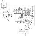
- FIG. 1 a portion surrounded by a broken line indicates a pump housing 1 of the high-pressure pump, and mechanisms and components shown in the broken line indicate that they are integrated into the pump housing 1 of the high-pressure pump. .
- the fuel in the fuel tank 20 is pumped up by the feed pump 21 based on a signal from an engine control unit 27 (hereinafter referred to as ECU), pressurized to an appropriate feed pressure, and passed through the suction pipe 28 to the suction port 10a of the high-pressure fuel supply pump. Sent to.
- ECU engine control unit 27
- the fuel that has passed through the suction port 10a passes through a filter 102 fixed in the suction joint 101, and further, an electromagnetically driven valve mechanism 30 that constitutes a variable capacity mechanism via the suction flow path 10b and the metal diaphragm dampers 9 and 10c. To the intake port 30a.
- the suction filter 102 in the suction joint 101 serves to prevent foreign matter existing between the fuel tank 20 and the suction port 10a from being absorbed into the high-pressure fuel supply pump by the flow of fuel.
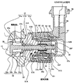
- FIG. 4 is an enlarged view of the electromagnetic intake valve mechanism 30 and shows a state where the electromagnetic coil 53 is not energized and is not energized.
- FIG. 5 is an enlarged view of the electromagnetic intake valve mechanism 30 and shows a state where the electromagnetic coil 53 is energized.
- the pump housing 1 is formed with a convex portion 1A as a pressurizing chamber 11 at the center, and a hole 30A for mounting the electromagnetic suction valve mechanism 30 is formed so that the pressurizing chamber 11 opens.
- the plunger rod 31 constituting the movable plunger is composed of three parts of a suction valve part 31a, a rod part 31b, and an anchor fixing part 31c, and an anchor 35 is welded and fixed to the anchor fixing part 31c by a welding part 37b.
- the spring 34 is fitted into the anchor inner periphery 35a and the first core portion inner periphery 33a as shown in the figure, and a spring force is generated by the spring 34 in a direction in which the anchor 35 and the first core portion 33 are separated.
- the valve seat member 32 includes a suction valve seat portion 32a, a suction passage portion 32b, a press-fit portion 32c, and a sliding bearing portion 32d.
- the press-fit portion 32 c is press-fitted and fixed in an annular recess at one end of the first core portion 33.
- a plurality of small holes 32e are provided in the press-fit portion 32c.
- a gap is formed between the outer periphery of the sliding bearing portion 32d and the inner peripheral surface of the first core 33, and communicates with the suction passage portion 32b through the small hole 32e so that fluid (fuel) can enter and exit. It is like that.
- the suction valve seat part 32a is press-fitted and fixed to the pump housing 1, and the pressurization chamber 11 and the suction port 30a are completely shut off by this press-fitting part.
- the first core portion 33 is welded and fixed to the pump housing 1 by a welded portion 37c, and shuts off the suction port 30a and the outside of the high-pressure fuel supply pump.
- the second core portion 36 is composed of a cap member made of a magnetic material, and is welded and fixed to the first core portion 33 by a welded portion 37a on the opening end side.
- the internal space composed of the first core portion 33 and the second core portion 36 is completely blocked from the external space.
- a magnetic orifice portion 36 a configured by an annular groove is provided on the outer peripheral surface of the second core portion 36.
- the plunger rod 31 When the electromagnetic coil 53 is not energized and is not energized, and when there is no fluid differential pressure between the suction channel 10c (suction port 30a) and the pressurizing chamber 11, the plunger rod 31 is As shown in FIG. 4, it moves to the right in the figure. In this state, the intake valve portion 31a and the intake valve seat portion 32a come into contact with each other and the intake port 38 is closed.
- the intake valve portion 31a is set to open by overcoming the urging force of the spring 34 and open the intake port 38 by the valve opening force due to the fluid differential pressure.
- the suction valve portion 31 a is completely opened and the anchor 31 is in contact with the first core portion 33.
- the suction valve portion 31 a does not open completely, and the anchor 31 does not contact the first core portion 33.
- the intake valve portion 31a When the intake valve portion 31a is fully open, the valve open state is maintained. On the other hand, when the intake valve portion 31a is not fully opened, the intake valve portion 31a is fully opened by encouraging the valve opening motion of the intake valve portion 31a, so that the anchor 31 is in contact with the first core portion 33, Then maintain that state.
- the volume of the pressurizing chamber 11 decreases with the compression movement of the piston plunger 2, but in this state, the fuel once sucked into the pressurizing chamber 11 once again passes through the suction port 38 in the valve-opened state, and the suction flow path 10c ( Since the pressure is returned to the suction port 30a), the pressure in the pressurizing chamber does not increase. This process is called a return process.
- the compression process of the piston plunger 2 (the ascending process from the lower start point to the upper start point) includes a return process and a discharge process.
- the amount of high-pressure fuel to be discharged can be controlled by controlling the timing at which the electromagnetic coil 53 of the electromagnetic intake valve mechanism 30 is de-energized.
- the ratio of the return process is small and the ratio of the discharge process is large during the compression process.
- the timing of releasing the input voltage is delayed, the ratio of the return process during the compression process is large and the ratio of the discharge process is small. That is, the amount of fuel returned to the suction passage 10c is large, and the amount of fuel discharged at high pressure is small.
- the timing for releasing the energization of the electromagnetic coil 53 is controlled by a command from the ECU.
- the amount of fuel discharged at a high pressure can be controlled to the amount required by the internal combustion engine by controlling the timing at which the energization of the electromagnetic coil 53 is released.
- the fuel guided to the fuel inlet 10a is pressurized to a high pressure by the reciprocating motion of the piston plunger 2 in the pressurizing chamber 11 of the pump housing 1, and is pumped from the fuel outlet 12 to the common rail 23. .
- the common rail 23 is provided with an injector 24 and a pressure sensor 26.
- the injectors 24 are mounted in accordance with the number of cylinders of the internal combustion engine, open and close according to a control signal from an engine control unit (ECU) 27, and inject fuel into the cylinders.
- ECU engine control unit
- the suction valve portion 31a repeats the opening / closing motion of the suction port 38 as the piston plunger 2 moves downward and upward, and the plunger rod 31 repeats the lateral movement in the drawing.
- the movement of the plunger rod 31 is limited to the movement in the horizontal direction in the drawing by the sliding bearing portion 32d of the valve seat member 32, and the sliding bearing portion 32d and the rod portion 31b repeat the sliding motion. . Therefore, the sliding portion needs to have a sufficiently low surface roughness so as not to be a resistance to the sliding movement of the plunger rod 31.
- the selection of the sliding clearance is as follows.
- the plunger rod 31 touches like a pendulum around the sliding portion, and the anchor 35 and the second core portion 36 come into contact with each other. If the plunger rod 31 slides, the anchor 35 and the second core portion 36 will also slide, so the resistance of the plunger rod 31 will increase, and the responsiveness of the opening / closing motion of the suction port 38 will be poor. Become. Further, since the anchor 35 and the second core portion 36 are made of ferritic magnetic stainless steel, there is a possibility that abrasion powder or the like is generated when they are slid. Furthermore, as will be described later, the smaller the gap between the anchor 35 and the second core portion 36, the greater the magnetic biasing force. If the gap is too large, the magnetic biasing force is insufficient, and the amount of fuel discharged at high pressure cannot be properly controlled. For these reasons, the gap between the anchor 35 and the second core portion 36 needs to be as small as possible and not in contact.
- the sliding part is provided in one place, and the sliding length L of the sliding bearing part 32d is sufficiently long as shown in the figure.
- the sliding part is formed by the inner diameter of the sliding bearing part 32d and the outer shape of the rod part 31b. Both of them require a tolerance, and the clearance of the sliding part also requires a tolerance.
- the clearance between the anchor 35 and the second core portion 36 has an upper limit value based on the magnetic biasing force as described above. In order to absorb this clearance tolerance and prevent the anchor 35 and the second core portion 36 from coming into contact with each other, the sliding length L may be increased to reduce the pendulum motion.
- the suction valve portion 31a and the suction valve seat portion 32a are not completely in surface contact when the suction port 38 is closed. This is because the verticality of the suction valve portion 31a and the rod portion 31b of the plunger rod 31 and the verticality of the suction valve seat portion 32a and the sliding bearing portion 32d of the valve seat member 32 cannot be absorbed by the clearance of the sliding portion. It is. If the suction valve portion 31a and the suction valve seat portion 32a are not completely in surface contact, the plunger rod 31 may be damaged due to excessive torque applied to the plunger rod 31 by the high pressure fuel in the pressurizing chamber 11 that has become high pressure during the discharge process. There is. In addition, an excessive load is applied to the sliding portion, and the sliding portion may be damaged or worn.
- the suction valve portion 31a and the suction valve seat portion 32a need to be in full surface contact.
- the pendulum motion of the plunger rod 31 is suppressed by increasing the sliding length L as described above, the perpendicularity of the intake valve portion 31a and the rod portion 31b of the plunger rod 31 and the valve seat member 32
- the accuracy required for the perpendicularity of the intake valve seat portion 32a and the sliding bearing portion 32d is increased.
- the valve seat member 32 is provided with a suction valve seat portion 32a and a sliding bearing portion 32d.
- the suction valve seat portion 32a and the sliding bearing portion 32d are made of the same member so that the verticality of the suction valve seat portion 32a and the sliding bearing portion 32d can be made with high accuracy. If the suction valve seat portion 32a and the sliding bearing portion 32d are separate members, a factor that makes the perpendicularity worse at the part to be processed and joined is necessarily generated. However, the suction valve seat portion 32a and the sliding bearing portion 32d are formed as one member. This solves this problem.
- the magnetic circuit formed around the electromagnetic coil 53 must generate a sufficient magnetic biasing force.
- the members constituting the magnetic circuit are the anchor 35, the first core portion 33, the yoke 51, and the second core portion 36 as shown in FIG. 5, and these are all magnetic materials.
- the magnetic flux does not pass directly between the first core portion 33 and the second core portion 36, and the anchor 35 is interposed. Need to pass through. This is to generate a magnetic urging force between the first core portion 33 and the anchor 35, and the magnetic flux directly passes between the first core portion 33 and the second core portion 36, and the magnetic flux passes through the anchor. If this decreases, the magnetic biasing force will decrease.
- an intermediate member is provided between the first core portion 33 and the second core portion 36. Since this intermediate member is a non-magnetic material, the magnetic flux does not pass directly between the first core portion 33 and the second core portion 36, and all the magnetic flux passes through the anchor 35.
- the first core portion 33 and the second core portion 36 are directly joined by the welded portion 37, and a magnetic orifice portion 36a that functions as a magnetic resistance in the closed magnetic path is provided on the outer periphery of the second core portion.
- An annular groove (36a) was formed.
- the thickness is made as thin as the strength allows, while the other portions of the second core portion 36 have a sufficient thickness.
- the magnetic orifice portion 36a is provided in the vicinity of the portion where the first core portion and the anchor 35 are in contact with each other.
- the magnetic flux that passes directly through the first core portion 33 and the second core portion is very small, thereby being generated between the first core portion 33 and the anchor 35.
- the reduction of the magnetic urging force is within an allowable range.
- the largest gap in the magnetic circuit is the radial direction formed between the inner peripheral surface of the second core portion 36 and the outer peripheral surface of the anchor 35. It is a gap. Since this radial gap is filled with fuel, the larger the gap, the greater the reluctance of the magnetic circuit. Therefore, the smaller the gap, the better.
- the radial gap between the second core portion 36 and the anchor 35 can be reduced by increasing the sliding length L of the sliding portion as described above.
- the electromagnetic coil 53 is formed by winding a lead wire 54 around an annular or cylindrical bobbin 52 made of a magnetic material with the axis of the plunger rod 31 as the center. Both ends (winding start and winding end) of the lead wire 54 are welded and connected to different terminals 56 by lead wire welding portions 55, respectively.
- the terminal 56 is formed of a conductive metal plate, one end is attached to one end portion of the resin bobbin 52, and the other end protrudes from the connector portion 58.
- the mating terminal can be contacted and current can flow through the coil.
- a molded resin is injected into the inside and outside of the yoke 51 to form a resin molded body 57.
- a part of the inner and outer peripheries on the open end side of the yoke 51, the inner peripheral surface of the bobbin, and a part of the terminal 56 are left, the weld joint 55 and the electromagnetic coil 53 are embedded in the resin, and the connector part 58 is Formed around the protruding part of the terminal.
- a small gap is provided between the outer peripheral surface of the core portion (33, 36) and the inner peripheral surface of the resin molded body (57, 380).
- the outer peripheral portion of the second core 36 of the suction valve unit 370 is inserted into the inner diameter portion of the resin molded body 57 with a minute gap. As a result, even if there is a molding tolerance of the molded resin body 57, the outer periphery of the second core portion 36 is not rubbed against the inner peripheral surface of the resin molded body 57, and an excessive force is applied to the resin molded body 57, causing cracks. Will not occur.
- Fig. 6 shows the conventional structure.
- the weld joint 55 between the lead wire and the end of the terminal is arranged inside the magnetic circuit, that is, inside the yoke 51.
- the entire length of the magnetic circuit, that is, the yoke 51 is lengthened by the axial dimension of the lead wire weld joint 55. This increases the magnetic resistance of the magnetic circuit, and there is a problem that the magnetic urging force generated between the first core portion 33 and the anchor 35 is reduced.
- the lead wire welded joint 55 is arranged outside the magnetic circuit, that is, the yoke 51.
- the lead wire welded joint 55 is disposed outside the magnetic circuit, that is, the yoke 51, and since there is no need for a space for accommodating the lead welded joint 55, the total length of the magnetic circuit can be shortened. It is possible to generate a sufficient magnetic biasing force between the anchor 33 and the anchor 35.
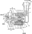
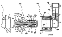
- FIG. 7 shows a state before the electromagnetic intake valve mechanism 30 is assembled into the pump housing 1.
- the suction valve unit 370 and the connector unit 380 (also referred to as a connector unit because of having the connector 58.
- the suction valve seat portion 32a of the suction valve unit 370 is press-fitted and fixed to the pump housing 1, and then the welding portion 37c is welded over the entire circumference.
- the welding is laser welding.
- the inner peripheral surface of the thin portion 51 ⁇ / b> A provided at the opening end of the yoke member 51 of the connector unit 380 is press-fitted and fixed to the outer periphery of the annular convex surface 31 ⁇ / b> A of the first core portion 33.
- the connector unit 380 can be press-fitted at any position 360 degrees with respect to the first core portion 33, so that the orientation of the connector 58 can be freely selected.
- the outer peripheral surface of the second core 33 and the inner peripheral surface of the bobbin, the outer peripheral surface of the second core 33 and the inner peripheral surface of the yoke member 51, the outer peripheral surface of the second core 33, and the inner periphery of the resin molded body 57 are provided so as not to contact any surfaces. It is desirable that the gap is set to a size that prevents the connector unit 380 from contacting any of the heads when the connector unit 380 resonates with engine vibration. In addition, this gap prevents the outer periphery of the second core member 36 from being pressed against the inner peripheral surface of the connector unit 380 when the connector unit 380 is assembled to the valve seat unit 370. To prevent it from being damaged.
- the gap should be as small as possible. It is convenient to reduce the magnetic resistance of the magnetic path.
- the gap in the bobbin 52 is somewhat large so that the second core member 36 can be easily inserted into the connector unit 380.
- this gap is set in consideration of these conditions. Specifically, it is the largest at the bobbin 52 (L1), the smallest at the bottom wall 51D of the cup-shaped yoke member 51, and the bottom wall 51D of the cup-shaped yoke member 51 at the resin molded body. Or a dimension slightly larger than the portion L1 of the bobbin 52.
- the weld joint 55 to which the winding start or winding end of the lead wire 54 constituting the electromagnetic coil 53 is electrically connected is provided outside the yoke member 51. Accordingly, the thickness of the bottom wall 51D of the cup-shaped yoke member 51 is reduced. As a result, the thickness of the bottom wall 51D of the cup-shaped yoke member 51 was reduced, and the area facing the second core member 36 in the thickness direction (magnetic flux passage area) was reduced. In the present embodiment, in order to compensate for this, the thickness of the flange 52B on the side opposite to the first core 31 of the bobbin 52 is reduced.
- the end surface 35F on the anti-first core 31 side of the anchor 35 can be wrapped in the thickness direction of the bottom wall 51D beyond the end surface K1 on the bobbin side of the bottom wall 51D of the cup-shaped yoke member 51. It was.
- cap-shaped portion of the second core member 36 is configured to protrude through the hole provided in the bottom wall 51D of the cup-shaped yoke member 51 to the outside of the bottom wall 51D of the cup-shaped yoke member 51. .
- the magnetic resistance can be reduced by shortening the distance between the end surface 35F of the anchor 35 and the inner peripheral surface 51F of the hole of the bottom wall 51D of the cup-shaped yoke member 51.
- the pump housing 1 is formed with a convex portion 1A as a pressurizing chamber 11 in the center, and a recess 11A for mounting the discharge valve unit 8 is formed through the peripheral wall of the pressurizing chamber 11.
- a discharge valve unit 8 is provided at the outlet of the pressurizing chamber 11.
- the discharge valve unit 8 includes a sheet member (valve seat) 8a, a discharge valve 8b, a discharge valve spring 8c, and a holding member 8d as a discharge valve stopper.
- the discharge valve unit 8 is welded to the outside of the pump housing 1 by welding a weld 8e. Assemble unit 8. Thereafter, the discharge valve unit 8 assembled from the left side in the figure is press-fitted and fixed to the pump housing 1.
- the press-fitting unit also has a function of blocking the pressurizing chamber 11 and the discharge port 12.
- the discharge valve 8b In a state where there is no differential pressure of fuel between the pressurizing chamber 11 and the discharge port 12, the discharge valve 8b is pressed against the seat member 8a by the urging force of the discharge valve spring 8c and is closed. Only when the fuel pressure in the pressurizing chamber 11 becomes larger than the fuel pressure in the discharge port 12 by a predetermined value, the discharge valve 8b is opened against the discharge valve spring 8c, and the pressure in the pressurizing chamber 11 is increased. The fuel is discharged to the common rail 23 through the discharge port 12.
- the discharge valve 8b When the discharge valve 8b is opened, it comes into contact with the holding member 8d and its operation is restricted. Therefore, the stroke of the discharge valve 8b is appropriately determined by the holding member 8d. If the stroke is too large, the fuel discharged to the fuel discharge port 12 will flow back into the pressurizing chamber 11 again due to the delay in closing the discharge valve 8b, and the efficiency of the high-pressure pump will decrease. . Further, when the discharge valve 8b repeats opening and closing movements, the holding member 8d guides the discharge valve 8b to move only in the stroke direction. By configuring as described above, the discharge valve unit 8 serves as a check valve that restricts the flow direction of fuel.
- the outer periphery of the cylinder 6 is held by a cylindrical fitting portion 7 a of the cylinder holder 7.
- the cylinder 6 is fixed to the pump housing 1 by screwing a screw 7 g threaded on the outer periphery of the cylinder holder 7 into a screw 1 b threaded on the pump housing 1.
- the plunger seal 13 is held at the lower end of the cylinder holder 7 by the seal holder 15 and the cylinder holder 7 that are press-fitted and fixed to the inner cylindrical surface portion 7 c of the cylinder holder 7. At this time, the plunger seal 13 is held by the inner cylindrical surface portion 7c of the cylinder holder 7 coaxially with the shaft of the cylindrical fitting portion 7a.
- the piston plunger 2 and the plunger seal 13 are installed in a slidable contact state at the lower end of the cylinder 6 in the figure.
- the cylinder holder 7 is provided with an outer cylindrical surface portion 7b, and a groove 7d for fitting the O-ring 61 is provided there.
- the O-ring 61 shuts off the engine cam side and the outside by the inner wall of the engine-side fitting hole 70 and the groove 7d of the cylinder holder 7 to prevent the engine oil from leaking to the outside.
- the cylinder 6 has a crimping part 6 a that intersects the reciprocating direction of the piston plunger 2, and the crimping part 6 a is crimped to the crimping surface 1 a of the pump housing 1. Crimping is performed by thrust generated by screw tightening.
- the pressurizing chamber 11 is formed by this pressure bonding, so that even if the fuel in the pressure chamber 11 is pressurized and becomes high pressure, the screw is not leaked from the pressure chamber 11 through the pressure bonding portion. Tightening torque must be managed.
- the structure is such that the cylinder 6 is inserted deeply into the pressurizing chamber 11.
- a clearance 1 ⁇ / b> B is provided between the outer periphery of the cylinder 6 and the inner periphery of the pump housing 1 on the pressure chamber 11 side from the crimping portion 6 a of the cylinder 6. Since the outer periphery of the cylinder 6 is held by the cylindrical fitting portion 7a of the cylinder holder 7, the clearance 1B is provided so that the outer periphery of the cylinder 6 and the inner periphery of the pump housing 1 do not come into contact with each other. it can.
- the cylinder 6 holds the piston plunger 2 that moves forward and backward in the pressurizing chamber 11 so as to be slidable along the forward and backward movement direction.
- a tappet 3 that converts the rotational movement of the cam 5 attached to the camshaft of the engine into a vertical movement and transmits it to the piston plunger 2.
- the piston plunger 2 is pressure-bonded to the tappet 3 by a spring 4 via a retainer 16.
- the retainer 16 is fixed to the piston plunger 2 by press-fitting. Thereby, the piston plunger 2 can be moved up and down (reciprocating) in accordance with the rotational movement of the cam 5.
- the piston plunger 2 repeats reciprocating motion inside the cylinder 6, but if the inner periphery of the cylinder 6 is distorted at that time, the piston plunger 2 and the cylinder 6 are seized and fixed. If fixed, it becomes impossible for the piston plunger 2 to reciprocate and high-pressure discharge of fuel becomes impossible.
- the outer cylindrical surface portion 7b and the cylindrical fitting portion 7a are provided in the cylinder holder 7. If the outer cylindrical surface portion 7b and the cylindrical fitting portion 7a are provided as separate members, a factor that deteriorates the degree of coincidence is inevitably generated in the parts to be processed and joined. This solves this problem.
- the cylinder 6 protrudes from the pressure-bonding portion 6a of the cylinder 6 toward the pressurizing chamber 11, and a clearance 1B is provided between the outer periphery of the cylinder 6 and the inner periphery of the pump housing 1.
- the pressure-bonding surfaces of the cylinder 6 and the pump housing 1 are set to intersect the reciprocating motion of the piston plunger 2, and the pressure-bonding surfaces are arranged outside the clearance 1b.
- the deformation of the pressure-bonding portion is difficult to be transmitted to the inner periphery of the cylinder 6, thereby minimizing the deformation of the inner periphery of the cylinder 6 and the cylinder 6 and the piston.
- the sliding length of the plunger 2 can be increased.
- ⁇ Another cause of sticking is the inclination of the piston plunger 2. This may occur when the coaxiality between the axis of the sliding part of the cylinder 6 and the piston plunger 2 and the axis of the sliding part of the plunger seal 13 and the piston plunger 2 are poor.
- the cylinder holder 7 is provided with the cylindrical fitting portion 7a and the inner cylindrical surface portion 7c. If the cylindrical fitting portion 7a and the inner cylindrical surface portion 7c are provided as separate members, a factor that deteriorates the degree of coincidence is inevitably caused in the parts to be processed and joined. This solves this problem.
- the cylindrical holder 7a, the outer cylindrical surface portion 7b, and the inner cylindrical surface portion 7c are all provided in the cylinder holder 7.
- the problem of the coaxiality of the outer cylindrical surface portion 7b and the cylindrical fitting portion 7a and the problem of the coaxiality of the cylindrical fitting portion 7a and the inner cylindrical surface portion 7c could be solved simultaneously.
- the deformation of the inner peripheral portion (sliding portion) of the cylinder 6 and the inclination of the piston plunger could be solved simultaneously.
- the suction channel 10c is connected to the seal chamber 10f via the suction channel 10d and the suction channel 10e provided in the cylinder holder 7, and the seal chamber 10f is always connected to the pressure of the intake fuel. ing.
- the fuel in the pressurizing chamber 11 is pressurized to a high pressure, a small amount of high-pressure fuel flows into the seal chamber 10f through the sliding clearance between the cylinder 6 and the piston plunger 2, but the inflowed high-pressure fuel is released to the suction pressure. Therefore, the plunger seal 13 is not damaged by the high pressure.
- the piston plunger 2 includes a large-diameter portion 2 a that slides with the cylinder 6 and a small-diameter portion 2 b that slides with the plunger seal 13.
- the diameter of the large diameter portion 2a is set larger than the diameter of the small diameter portion 2b, and is set coaxially with each other.
- the sliding part with the cylinder 6 is the large diameter part 2a
- the sliding part with the plunger seal 13 is the small diameter part 2b.
- the friction area becomes smaller as the diameter of the sliding portion with the plunger seal 13 is smaller, the frictional heat generated by the sliding motion is also reduced.
- it is the small-diameter portion 2b of the piston plunger 2 that slides with the plunger seal 13, so the amount of heat generated by friction with the plunger seal 13 can be kept small, and seizure sticking can be prevented. .
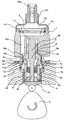
- FIG. 8 shows a state before the cylinder holder 7 is fixed to the pump housing 1 with screws.
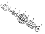
- a plunger unit 80 is formed by the piston plunger 2, the cylinder 6, the seal holder 15, the plunger seal 13, the cylinder holder 7, the spring 4, and the retainer 16.
- FIG. 9 shows a method for assembling the plunger unit 80.
- the piston plunger 2, the cylinder 6, the seal holder 15, and the plunger seal 13 are assembled into the cylinder holder 7 from the upper left in the figure.
- the seal holder 15 is press-fitted and fixed to the inner cylindrical surface portion 7 c of the cylinder holder 7.
- the spring 4 and the retainer 16 are assembled from the lower right side in the figure.
- the retainer 16 is press-fitted and fixed to the piston plunger 2.
- the assembled plunger unit 80 is attached to the pump housing 1 with screws as described above after the O-ring 61 and the O-ring 62 are mounted. Tightening is performed by a hexagonal portion 7e formed in the cylinder holder 7.
- the hexagonal portion 7e has an inner hexagonal shape, and generates torque with a dedicated tool to tighten the screw. By managing this torque, the pressure contact pressure between the pressure bonding part 6a and the pressure bonding surface 1a is managed.
- An O-ring 62 is attached to the outer peripheral groove 7 f of the cylinder 7.
- the metal diaphragm damper 9 is composed of two metal diaphragms, and the outer periphery is fixed to each other by welding at the welded portion in a state where gas is sealed in the space between both diaphragms.
- the metal diaphragm damper 9 changes its volume, thereby reducing the low pressure pulsation.
- the high pressure fuel supply pump is fixed to the engine by the flange 41, the set screw 42, and the bush 43.
- the flange 41 is welded to the pump housing 1 by welding at a welded portion 41a. In this embodiment, laser welding is used.
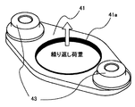
- FIG. 10 shows an external view of the flange 41 and the bush 43. In this figure, only the flange 41 and the bush 43 are shown, and other components are not shown.
- the two bushes 43 are attached to the flange 41 and attached to the opposite side of the engine.
- the two set screws 42 are screwed into respective screws formed on the engine side, and the two bushes 43 and the flange 41 are pressed against the engine to fix the high pressure fuel supply pump to the engine.
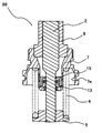
- FIG. 11 shows an enlarged view of the flange 41, the set screw 42, and the bush 43 part.
- the bush 43 has a collar portion 43a and a caulking portion 43b.
- the caulking portion 43 b is caulked and coupled to the mounting hole of the flange 41.
- the pump housing 1 and the welded portion 41a are welded together by laser welding.
- the resin fastener 44 is inserted into the bush 43, and the set screw 42 is inserted into the fastener 44.
- the fastener 44 serves to temporarily fix the set screw 42 to the bush 43. That is, the set screw 42 is fixed so as not to fall off the bush 43 until the high-pressure fuel supply pump is attached to the engine.
- the set screw 42 is screwed and fixed to a screw portion provided on the engine side. At that time, the set screw 42 is rotated in the bush 43 by the tightening torque of the set screw 42. it can.
- the pressure in the pressurizing chamber 11 repeats high pressure and low pressure as described above.
- a force acts so that the pump housing 1 is lifted upward in the figure due to this pressure. This force does not work when the pressure chamber 11 is at a low pressure. For this reason, the pump housing repeatedly receives a load upward in the drawing.
- the flange 41 fixes the pump housing 1 to the engine by two set screws 42. Therefore, when the pump housing 1 is lifted upward as described above, the flange 42 is in a state where the two set screws 42 and the bush 43 are fixed and a bending load is repeatedly applied to the central portion. Due to this repeated load, the flange 41 and the pump housing 1 are deformed, and therefore, there is a problem that repeated stress is generated and fatigue failure occurs. Furthermore, since the cylinder holder 7 and the cylinder 6 are also deformed, the sliding portion of the cylinder 6 is also deformed, and the above-described seizure and sticking between the piston plunger 2 and the cylinder 6 occurs.
- the flange 41 In order to weld through the flange 41 by laser welding, it is sufficient to increase the output of the laser. However, since heat is always generated during welding, the flange 41 is thermally deformed by the heat. Further, a large amount of spatter generated during welding is generated and fixed to the pump housing 1 and other components. From the above viewpoint, the welding length for through welding by laser welding is better.
- the flange 41a can be through-welded by laser welding, and the occurrence of spatter can be minimized.
- the upper end surface and the lower end surface of the welded part 41a are always raised more than the base material.
- the pump housing 1 when a repeated load is applied to the pump housing 1, it is bent in the direction of the repeated load with the two set screws 42 and the bush 43 being fixed.
- the welded portion 41 a is welded through the entire circumference by laser welding, and the curvature of the flange 41 spreads to the pump housing 1.
- the cylinder holder 7 and the pump housing 1 are in contact only with screws 7g and 1b.
- the screw 1b and the welded portion 41a of the pump housing 1 are present at a position where they want to be separated by a distance m.
- the minimum wall thickness at the distance m is n. Even if the pump housing 1 is deformed by the bending of the flange 41, the deformation is absorbed by the portion of the distance m and the wall thickness n, and the values of m and n are selected so as not to reach the screw 1b.
- FIG. 12 shows an enlarged view near the welded portion 41a.
- the maximum stress generated when the pump housing 1 is pulled upward in the figure by repeated load and the flange 41 is bent is the arrow on the surface of the pump housing 1 as shown as the maximum stress in FIG. Occurs in the direction.
- the generated stress may be dispersed as much as possible by the shape effect so as not to cause stress concentration.
- the R portion 1c and the R portion 1e are connected by the straight portion 1d, and the optimum value is selected.
- the straight part 1d exists between the two R parts 1c and 1e, and the stress generated on the straight part 1d is evenly distributed. As a result, the maximum value of the generated stress could be reduced without causing stress concentration.
- the bending effective distance: O indicates the shortest distance between the end portions of the two bushes 43, and this portion is substantially bent by a repeated load. If the effective bending distance O can be reduced, the rigidity of the flange 41 is improved as a result.
- the bush 43 is provided with a flange portion 43a to reduce the bending effective distance: O.
- a height for inserting the fastener 44 is required.
- the outer shape of the bush 43 is increased at that height, there are problems such as interference with the pump housing 1 and an increase in the material of the bush 43.
- the flange portion 43a By providing the flange portion 43a, these problems can be prevented and the curvature effective distance O can be reduced.
- valve seat 52 valve seat 52
- a movable plunger valve stem 92
- valve member (94) attached to the tip thereof are used.
- the bearing member bearing 98
- the fluid leakage of the seat portion of the electromagnetically driven valve mechanism used in the variable displacement control mechanism of the high-pressure fuel supply pump can be reduced.
- valve seat member and the valve member are configured as one part processed from the same member.
- the gap between the movable plunger and the bearing can be made smaller than before, and as a result, the tilt of the movable plunger can be suppressed, the sealing performance between the valve seat member and the valve member can be improved, and the fluid control accuracy can be improved.
- Embodiment 1 An open-type valve member provided at the fluid inlet, Movable plunger operated by electromagnetic force, A holder for fixing the cylinder to the pump housing; A regulating member that regulates the displacement of the plunger at a specific position; A spring member for urging the movable plunger to the side opposite to the regulating member; An electromagnetic drive mechanism for energizing the movable plunger electromagnetically to energize the valve member and the movable plunger in a direction to close the fluid intake port; A valve seat from which the valve member comes into close contact, In what comprises a bearing member that supports the movable plunger so as to reciprocate, An electromagnetically driven valve mechanism in which the valve seat and the bearing member are configured as a single part processed from the same member.
- Embodiment 2 In what is described in Embodiment 1, An anchor is fixed to the end of the movable plunger opposite to the valve member, This anchor is arranged to face the regulating member via a magnetic gap,
- the restriction member constitutes a magnetic core part of the electromagnetic drive mechanism
- a cap member made of a magnetic material surrounding the anchor and the magnetic gap and sealing the inside is fixed to the magnetic core portion of the restriction member
- An electromagnetic coil is attached to the outer periphery of the cap member made of magnetic material
- An electromagnetically driven valve mechanism having a yoke member that forms a magnetic passage in cooperation with the anchor, the magnetic gap, the magnetic core, and the cap member made of the magnetic material on the outer periphery thereof.
- the electromagnetic drive mechanism has a body portion made of a magnetic material, An electromagnetically driven valve mechanism in which the bearing member is press-fitted and fixed to an inner peripheral wall of an internal through hole formed in the body portion of the electromagnetically driven mechanism.
- Embodiment 4 In what is described in Embodiment 1, An anchor is fixed to the end of the movable plunger opposite to the valve member, This anchor is arranged to face the regulating member via a magnetic gap,
- the restriction member constitutes a magnetic core part of the electromagnetic drive mechanism
- a cap member made of a magnetic material surrounding the anchor and the magnetic gap and sealing the inside is fixed to the magnetic core portion of the restriction member
- An electromagnetic coil is attached to the outer periphery of the cap member made of magnetic material
- a yoke member that forms a magnetic passage in cooperation with the anchor, the magnetic gap, the magnetic core, and the cap member made of the magnetic material is provided on the outer periphery
- the electromagnetic drive mechanism has a body portion made of a magnetic material
- An electromagnetically driven valve mechanism in which the bearing member is press-fitted and fixed to an inner peripheral wall of an internal through hole formed in the body portion of the electromagnetically driven mechanism.
- Embodiment 5 In any one of Embodiments 2 and 4, An electromagnetically driven valve mechanism in which a helical spring as the spring member is mounted on the outer periphery of the movable plunger at the inner periphery of the anchor.
- Embodiment 6 In any one of Embodiments 2, 4 to 5, An electromagnetically driven valve mechanism in which the center of gravity in the axial direction between the integral movable plunger and the valve member is positioned closer to the anchor side than the axial center of the bearing member in a state where the anchor is mounted.
- Embodiment 7 In any one of Embodiments 2 and 4, A resin molded body part surrounding at least a part of the outer periphery of the yoke member; An electromagnetically driven valve mechanism in which a connector is integrally provided on the resin molded body portion, and a joint portion between a terminal of the connector and a terminal of the electromagnetic coil is formed outside the yoke member.
- Embodiment 8 In the embodiment described in Embodiment 1, A force other than the electromagnetic force assists the movement of the movable plunger in the same direction as the movement of the movable plunger by the electromagnetic force, and the movable plunger moves in the direction of the regulating member by a force other than the electromagnetic force.
- An electromagnetically driven valve mechanism configured to cause the electromagnetic force to act on the plunger after a specific displacement.
- Embodiment 9 In the embodiment described in Embodiment 1, After the valve member is initially opened against the force of the spring member due to the fluid pressure difference between the upstream side and the downstream side of the valve member, the valve member is maintained in a direction that maintains or promotes the opening direction of the valve member.
- An electromagnetically driven valve mechanism wherein an electromagnetically driven mechanism is configured to bias the movable plunger.
- a high-pressure fuel supply pump having a suction valve configured by the electromagnetically driven valve mechanism according to any one of the first to seventh embodiments.
- a high-pressure fuel supply pump characterized in that the intake valve member maintains an open operation and an open state.
- Embodiment 13 In any one of Embodiments 10 to 12, An input voltage is applied to the electromagnetic drive mechanism after the suction valve member is opened against the urging force of the spring member due to a fluid differential pressure between the suction flow path side of the suction valve member and the pressurizing chamber side.
- the high-pressure fuel supply pump is characterized in that the opening operation of the intake valve member is maintained or promoted.
- a high-pressure fuel supply pump wherein the flow rate of high-pressure discharge is controlled by controlling the timing of releasing the input voltage applied to the electromagnetic drive mechanism in accordance with the movement of the piston plunger.
- a high-pressure fuel supply pump wherein a current value generated in the electromagnetic drive mechanism is controlled by changing an input voltage.
- a high-pressure fuel supply pump characterized in that the application and release of the input voltage are periodically repeated in a shorter cycle between the application of the input voltage to the electromagnetic drive mechanism and the release of the input voltage.
- the electromagnetically driven valve mechanism itself according to the present invention can be used for control of fluids including fuel. Even when used for a high-pressure fuel pump, it can be used not only for a suction valve mechanism as in the embodiment but also as a spill valve provided in a spill passage separately from the suction valve.
Landscapes
- Engineering & Computer Science (AREA)
- Mechanical Engineering (AREA)
- General Engineering & Computer Science (AREA)
- Chemical & Material Sciences (AREA)
- Combustion & Propulsion (AREA)
- Fuel-Injection Apparatus (AREA)
Priority Applications (3)
| Application Number | Priority Date | Filing Date | Title |
|---|---|---|---|
| US13/125,106 US9410519B2 (en) | 2008-10-30 | 2009-10-29 | High-pressure fuel pump assembly mechanism |
| CN200980142941.6A CN102197212B (zh) | 2008-10-30 | 2009-10-29 | 高压燃料供给泵 |
| EP09823679.7A EP2341237B1 (en) | 2008-10-30 | 2009-10-29 | Pump for supplying high-pressure fuel |
Applications Claiming Priority (2)
| Application Number | Priority Date | Filing Date | Title |
|---|---|---|---|
| JP2008-279041 | 2008-10-30 | ||
| JP2008279041A JP5478051B2 (ja) | 2008-10-30 | 2008-10-30 | 高圧燃料供給ポンプ |
Publications (1)
| Publication Number | Publication Date |
|---|---|
| WO2010050569A1 true WO2010050569A1 (ja) | 2010-05-06 |
Family
ID=42128928
Family Applications (1)
| Application Number | Title | Priority Date | Filing Date |
|---|---|---|---|
| PCT/JP2009/068617 Ceased WO2010050569A1 (ja) | 2008-10-30 | 2009-10-29 | 高圧燃料供給ポンプ |
Country Status (5)
| Country | Link |
|---|---|
| US (1) | US9410519B2 (enExample) |
| EP (1) | EP2341237B1 (enExample) |
| JP (1) | JP5478051B2 (enExample) |
| CN (1) | CN102197212B (enExample) |
| WO (1) | WO2010050569A1 (enExample) |
Families Citing this family (33)
| Publication number | Priority date | Publication date | Assignee | Title |
|---|---|---|---|---|
| JP5372692B2 (ja) * | 2009-10-06 | 2013-12-18 | 日立オートモティブシステムズ株式会社 | 高圧燃料ポンプ |
| US8646436B2 (en) * | 2010-07-06 | 2014-02-11 | Toyota Boshoku Kabushiki Kaisha | Fuel pump attachment structure |
| CN103649520B (zh) * | 2011-05-13 | 2016-05-04 | 株式会社三国 | 高压燃料泵装置 |
| EP2535554A1 (en) * | 2011-06-15 | 2012-12-19 | Delphi Technologies Holding S.à.r.l. | Electro-valve for discharging common rail |
| JP5628121B2 (ja) | 2011-09-20 | 2014-11-19 | 日立オートモティブシステムズ株式会社 | 高圧燃料供給ポンプ |
| DE102011083787A1 (de) * | 2011-09-29 | 2013-04-04 | Hengst Gmbh & Co. Kg | Kraftstoffpumpanordnung |
| CN106014736B (zh) * | 2011-11-30 | 2019-04-09 | 日立汽车系统株式会社 | 高压燃料供给泵 |
| US10422330B2 (en) * | 2011-11-30 | 2019-09-24 | Hitachi Automotive Systems, Ltd. | High pressure fuel pump |
| DE102013204549A1 (de) * | 2013-03-15 | 2014-09-18 | Robert Bosch Gmbh | Hochdruckpumpe, insbesondere Steckpumpe, für ein Kraftstoffsystem für eine Brennkraftmaschine |
| DE102013219712B4 (de) * | 2013-09-30 | 2020-04-23 | Continental Automotive Gmbh | Dämpfer mit Stützring für eine Dichtung |
| JP6387812B2 (ja) * | 2014-12-05 | 2018-09-12 | 株式会社デンソー | 高圧ポンプ、及び、それを用いる燃料供給システム |
| GB201508608D0 (en) * | 2015-05-20 | 2015-07-01 | Delphi Int Operations Lux Srl | Fuel pump apparatus |
| GB2544527A (en) * | 2015-11-20 | 2017-05-24 | Gm Global Tech Operations Llc | Fuel unit pump assembly comprising an isolator |
| DE102016206459B3 (de) * | 2016-04-18 | 2017-10-05 | Continental Automotive Gmbh | Kombination, umfassend ein Gehäuse und einen Flansch, und Anordnung |
| DE102016206456B4 (de) * | 2016-04-18 | 2017-11-09 | Continental Automotive Gmbh | Kombination, umfassend ein Gehäuse und einen Flansch, und Anordnung |
| JP6569589B2 (ja) | 2016-04-28 | 2019-09-04 | 株式会社デンソー | 高圧ポンプ |
| DE102016213451A1 (de) | 2016-05-19 | 2017-11-23 | Robert Bosch Gmbh | Kraftstoff-Hochdruckpumpe |
| US20170335834A1 (en) * | 2016-05-23 | 2017-11-23 | Caterpillar Inc. | Pump for fluid system and method of operating same |
| DE102016217409A1 (de) * | 2016-09-13 | 2018-03-15 | Robert Bosch Gmbh | Kraftstoff-Hochdruckpumpe |
| JP2018178969A (ja) * | 2017-04-21 | 2018-11-15 | 日立オートモティブシステムズ株式会社 | 高圧燃料供給ポンプ |
| DE102017207207A1 (de) * | 2017-04-28 | 2018-10-31 | Robert Bosch Gmbh | Kraftstoffpumpe |
| JP6397961B2 (ja) * | 2017-05-22 | 2018-09-26 | 日立オートモティブシステムズ株式会社 | 高圧燃料供給ポンプ |
| JP7022380B2 (ja) * | 2018-01-31 | 2022-02-18 | いすゞ自動車株式会社 | 燃料ポンプ組付構造 |
| US20190285032A1 (en) * | 2018-03-14 | 2019-09-19 | Nostrum Energy Pte. Ltd. | Pump for internal combustion engine and method of forming the same |
| JP6681448B2 (ja) * | 2018-08-31 | 2020-04-15 | 日立オートモティブシステムズ株式会社 | 高圧燃料供給ポンプ |
| WO2020175048A1 (ja) * | 2019-02-25 | 2020-09-03 | 日立オートモティブシステムズ株式会社 | 燃料ポンプ |
| DE102019204995B4 (de) * | 2019-04-08 | 2024-03-07 | Vitesco Technologies GmbH | Pumpe für ein Kraftfahrzeug und Verfahren zum Herstellen einer Pumpe |
| GB2591519B (en) * | 2020-02-03 | 2024-03-27 | Delphi Automotive Systems Lux | Inlet metering valve for an engine fuel pump |
| DE102020104313B3 (de) * | 2020-02-19 | 2021-01-28 | Schaeffler Technologies AG & Co. KG | Stößel zur Beaufschlagung eines Pumpenkolbens einer Kraftstoffhochdruckpumpe |
| CN115803515A (zh) * | 2020-07-17 | 2023-03-14 | 日立安斯泰莫株式会社 | 燃料泵 |
| JP7783702B2 (ja) * | 2021-07-06 | 2025-12-10 | 三菱重工エンジン&ターボチャージャ株式会社 | 燃料ポンプ |
| US11939941B2 (en) * | 2022-03-24 | 2024-03-26 | Delphi Technologies Ip Limited | Gasoline direct injection fuel pump with isolated plunger sleeve |
| GB2626767B (en) * | 2023-02-02 | 2025-04-23 | Phinia Delphi Luxembourg Sarl | Pump-flange assembly process |
Citations (2)
| Publication number | Priority date | Publication date | Assignee | Title |
|---|---|---|---|---|
| JPH08105566A (ja) | 1994-09-09 | 1996-04-23 | General Motors Corp <Gm> | 弁組立体 |
| EP1519033A2 (de) | 2003-09-25 | 2005-03-30 | Robert Bosch Gmbh | Kolbenpumpe, insbesondere Hochdruck-Kolbenpumpe |
Family Cites Families (29)
| Publication number | Priority date | Publication date | Assignee | Title |
|---|---|---|---|---|
| IT1204924B (it) * | 1986-03-22 | 1989-03-10 | Bosch Gmbh Robert | Pompa di iniezione del carburante per motori endotermici |
| CH672168A5 (enExample) * | 1987-01-30 | 1989-10-31 | Nova Werke Ag | |
| JP3180948B2 (ja) * | 1996-09-03 | 2001-07-03 | 株式会社ボッシュオートモーティブシステム | ダイヤフラム型ダンパ |
| JP3309765B2 (ja) * | 1997-05-16 | 2002-07-29 | 三菱電機株式会社 | 高圧燃料供給ポンプ |
| JP2857139B1 (ja) * | 1998-01-30 | 1999-02-10 | 三菱電機株式会社 | 高圧燃料供給ポンプ |
| FI108071B (fi) * | 1998-07-03 | 2001-11-15 | Waertsilae Tech Oy Ab | Integroitu pumppu- ja nostinyksikkö polttoaineensyöttöjärjestelmässä |
| GB9917998D0 (en) * | 1999-07-30 | 1999-09-29 | Lucas Ind Plc | Fuel pump |
| JP2001059466A (ja) * | 1999-08-20 | 2001-03-06 | Mitsubishi Electric Corp | 高圧燃料ポンプ |
| JP3767268B2 (ja) * | 1999-09-10 | 2006-04-19 | 三菱電機株式会社 | 高圧燃料供給装置 |
| JP2001221129A (ja) * | 2000-02-10 | 2001-08-17 | Hitachi Ltd | 高圧燃料ポンプ |
| DE60045422D1 (de) * | 2000-08-24 | 2011-02-03 | Mitsubishi Electric Corp | Hochdruckbrennstoffzufuhrvorrichtung |
| JP4006336B2 (ja) * | 2001-01-05 | 2007-11-14 | 株式会社日立製作所 | 高圧燃料供給ポンプ |
| JP3787508B2 (ja) * | 2001-07-19 | 2006-06-21 | 株式会社日立製作所 | 高圧燃料供給ポンプ |
| JP3823060B2 (ja) * | 2002-03-04 | 2006-09-20 | 株式会社日立製作所 | 高圧燃料供給ポンプ |
| JP3693992B2 (ja) * | 2002-11-08 | 2005-09-14 | 三菱電機株式会社 | 高圧燃料ポンプ |
| JP2004211574A (ja) * | 2002-12-27 | 2004-07-29 | Hitachi Ltd | 燃料ポンプ |
| DE10322604A1 (de) * | 2003-05-20 | 2004-12-09 | Robert Bosch Gmbh | Satz von Kolbenpumpen, insbesondere Kraftstoffpumpen für Brennkraftmaschinen mit Kraftstoff-Direkteinspritzung |
| DE10322599B4 (de) * | 2003-05-20 | 2013-08-08 | Robert Bosch Gmbh | Kolbenpumpe, insbesondere Hochdruck-Kraftstoffpumpe |
| JP4036153B2 (ja) * | 2003-07-22 | 2008-01-23 | 株式会社日立製作所 | ダンパ機構及び高圧燃料供給ポンプ |
| JP4415884B2 (ja) * | 2005-03-11 | 2010-02-17 | 株式会社日立製作所 | 電磁駆動機構,電磁弁機構及び電磁駆動機構によって操作される吸入弁を備えた高圧燃料供給ポンプ,電磁弁機構を備えた高圧燃料供給ポンプ |
| DE102005033634A1 (de) * | 2005-07-19 | 2007-01-25 | Robert Bosch Gmbh | Hochdruck-Kraftstoffpumpe für ein Kraftstoff-Einspritzsystem einer Brennkraftmaschine |
| JP4415929B2 (ja) * | 2005-11-16 | 2010-02-17 | 株式会社日立製作所 | 高圧燃料供給ポンプ |
| JP4648254B2 (ja) * | 2006-06-22 | 2011-03-09 | 日立オートモティブシステムズ株式会社 | 高圧燃料ポンプ |
| JP4625789B2 (ja) * | 2006-07-20 | 2011-02-02 | 日立オートモティブシステムズ株式会社 | 高圧燃料ポンプ |
| JP2008057451A (ja) * | 2006-08-31 | 2008-03-13 | Hitachi Ltd | 高圧燃料供給ポンプ |
| EP2122168B1 (en) * | 2007-01-10 | 2015-12-09 | Stanadyne Corporation | Load ring mounting of pumping plunger |
| JP4686501B2 (ja) * | 2007-05-21 | 2011-05-25 | 日立オートモティブシステムズ株式会社 | 液体脈動ダンパ機構、および液体脈動ダンパ機構を備えた高圧燃料供給ポンプ |
| JP5039507B2 (ja) * | 2007-10-31 | 2012-10-03 | 日立オートモティブシステムズ株式会社 | 高圧燃料供給ポンプおよびその製造方法 |
| JP5002523B2 (ja) * | 2008-04-25 | 2012-08-15 | 日立オートモティブシステムズ株式会社 | 燃料の圧力脈動低減機構、及びそれを備えた内燃機関の高圧燃料供給ポンプ |
-
2008
- 2008-10-30 JP JP2008279041A patent/JP5478051B2/ja active Active
-
2009
- 2009-10-29 CN CN200980142941.6A patent/CN102197212B/zh active Active
- 2009-10-29 WO PCT/JP2009/068617 patent/WO2010050569A1/ja not_active Ceased
- 2009-10-29 US US13/125,106 patent/US9410519B2/en active Active
- 2009-10-29 EP EP09823679.7A patent/EP2341237B1/en active Active
Patent Citations (2)
| Publication number | Priority date | Publication date | Assignee | Title |
|---|---|---|---|---|
| JPH08105566A (ja) | 1994-09-09 | 1996-04-23 | General Motors Corp <Gm> | 弁組立体 |
| EP1519033A2 (de) | 2003-09-25 | 2005-03-30 | Robert Bosch Gmbh | Kolbenpumpe, insbesondere Hochdruck-Kolbenpumpe |
Non-Patent Citations (1)
| Title |
|---|
| See also references of EP2341237A4 * |
Also Published As
| Publication number | Publication date |
|---|---|
| JP2010106740A (ja) | 2010-05-13 |
| CN102197212A (zh) | 2011-09-21 |
| EP2341237A4 (en) | 2017-05-17 |
| CN102197212B (zh) | 2014-07-30 |
| JP5478051B2 (ja) | 2014-04-23 |
| EP2341237A1 (en) | 2011-07-06 |
| US9410519B2 (en) | 2016-08-09 |
| US20110253109A1 (en) | 2011-10-20 |
| EP2341237B1 (en) | 2018-07-18 |
Similar Documents
| Publication | Publication Date | Title |
|---|---|---|
| JP5478051B2 (ja) | 高圧燃料供給ポンプ | |
| JP4866893B2 (ja) | 電磁駆動型弁機構及びこれを用いた高圧燃料供給ポンプ | |
| JP2010106740A5 (enExample) | ||
| JP5537498B2 (ja) | 電磁吸入弁を備えた高圧燃料供給ポンプ | |
| JP5286221B2 (ja) | 高圧燃料供給ポンプの吐出弁機構 | |
| JP5909502B2 (ja) | 高圧燃料供給ポンプ | |
| JP6779370B2 (ja) | 高圧燃料ポンプ | |
| JP2019031977A (ja) | 高圧燃料供給ポンプ | |
| JP5905046B2 (ja) | 電磁吸入弁を備えた高圧燃料供給ポンプ | |
| JP5244761B2 (ja) | 高圧燃料供給ポンプ | |
| WO2021054006A1 (ja) | 電磁吸入弁及び高圧燃料供給ポンプ | |
| JP6681448B2 (ja) | 高圧燃料供給ポンプ | |
| JP5081869B2 (ja) | 高圧燃料供給ポンプ | |
| JP2018119479A (ja) | 高圧燃料ポンプ | |
| JP6151399B2 (ja) | 高圧燃料供給ポンプ | |
| WO2016051909A1 (ja) | バルブ機構、およびこのバルブ機構を吐出弁機構として備えた高圧燃料供給ポンプ | |
| JP6397961B2 (ja) | 高圧燃料供給ポンプ | |
| JP7077212B2 (ja) | 高圧燃料ポンプ | |
| JP6047648B2 (ja) | 電磁吸入弁を備えた高圧燃料供給ポンプ | |
| JP2018031332A (ja) | 高圧燃料供給ポンプ |
Legal Events
| Date | Code | Title | Description |
|---|---|---|---|
| WWE | Wipo information: entry into national phase |
Ref document number: 200980142941.6 Country of ref document: CN |
|
| 121 | Ep: the epo has been informed by wipo that ep was designated in this application |
Ref document number: 09823679 Country of ref document: EP Kind code of ref document: A1 |
|
| WWE | Wipo information: entry into national phase |
Ref document number: 2009823679 Country of ref document: EP |
|
| NENP | Non-entry into the national phase |
Ref country code: DE |
|
| WWE | Wipo information: entry into national phase |
Ref document number: 13125106 Country of ref document: US |