EP1519033A2 - Kolbenpumpe, insbesondere Hochdruck-Kolbenpumpe - Google Patents
Kolbenpumpe, insbesondere Hochdruck-Kolbenpumpe Download PDFInfo
- Publication number
- EP1519033A2 EP1519033A2 EP04104464A EP04104464A EP1519033A2 EP 1519033 A2 EP1519033 A2 EP 1519033A2 EP 04104464 A EP04104464 A EP 04104464A EP 04104464 A EP04104464 A EP 04104464A EP 1519033 A2 EP1519033 A2 EP 1519033A2
- Authority
- EP
- European Patent Office
- Prior art keywords
- piston
- piston pump
- spring plate
- supported
- spring
- Prior art date
- Legal status (The legal status is an assumption and is not a legal conclusion. Google has not performed a legal analysis and makes no representation as to the accuracy of the status listed.)
- Withdrawn
Links
Images

Classifications
-
- F—MECHANICAL ENGINEERING; LIGHTING; HEATING; WEAPONS; BLASTING
- F02—COMBUSTION ENGINES; HOT-GAS OR COMBUSTION-PRODUCT ENGINE PLANTS
- F02M—SUPPLYING COMBUSTION ENGINES IN GENERAL WITH COMBUSTIBLE MIXTURES OR CONSTITUENTS THEREOF
- F02M59/00—Pumps specially adapted for fuel-injection and not provided for in groups F02M39/00 -F02M57/00, e.g. rotary cylinder-block type of pumps
- F02M59/44—Details, components parts, or accessories not provided for in, or of interest apart from, the apparatus of groups F02M59/02 - F02M59/42; Pumps having transducers, e.g. to measure displacement of pump rack or piston
-
- F—MECHANICAL ENGINEERING; LIGHTING; HEATING; WEAPONS; BLASTING
- F02—COMBUSTION ENGINES; HOT-GAS OR COMBUSTION-PRODUCT ENGINE PLANTS
- F02M—SUPPLYING COMBUSTION ENGINES IN GENERAL WITH COMBUSTIBLE MIXTURES OR CONSTITUENTS THEREOF
- F02M59/00—Pumps specially adapted for fuel-injection and not provided for in groups F02M39/00 -F02M57/00, e.g. rotary cylinder-block type of pumps
- F02M59/02—Pumps specially adapted for fuel-injection and not provided for in groups F02M39/00 -F02M57/00, e.g. rotary cylinder-block type of pumps of reciprocating-piston or reciprocating-cylinder type
- F02M59/10—Pumps specially adapted for fuel-injection and not provided for in groups F02M39/00 -F02M57/00, e.g. rotary cylinder-block type of pumps of reciprocating-piston or reciprocating-cylinder type characterised by the piston-drive
- F02M59/102—Mechanical drive, e.g. tappets or cams
-
- F—MECHANICAL ENGINEERING; LIGHTING; HEATING; WEAPONS; BLASTING
- F02—COMBUSTION ENGINES; HOT-GAS OR COMBUSTION-PRODUCT ENGINE PLANTS
- F02M—SUPPLYING COMBUSTION ENGINES IN GENERAL WITH COMBUSTIBLE MIXTURES OR CONSTITUENTS THEREOF
- F02M63/00—Other fuel-injection apparatus having pertinent characteristics not provided for in groups F02M39/00 - F02M57/00 or F02M67/00; Details, component parts, or accessories of fuel-injection apparatus, not provided for in, or of interest apart from, the apparatus of groups F02M39/00 - F02M61/00 or F02M67/00; Combination of fuel pump with other devices, e.g. lubricating oil pump
- F02M63/02—Fuel-injection apparatus having several injectors fed by a common pumping element, or having several pumping elements feeding a common injector; Fuel-injection apparatus having provisions for cutting-out pumps, pumping elements, or injectors; Fuel-injection apparatus having provisions for variably interconnecting pumping elements and injectors alternatively
- F02M63/0225—Fuel-injection apparatus having a common rail feeding several injectors ; Means for varying pressure in common rails; Pumps feeding common rails
-
- F—MECHANICAL ENGINEERING; LIGHTING; HEATING; WEAPONS; BLASTING
- F04—POSITIVE - DISPLACEMENT MACHINES FOR LIQUIDS; PUMPS FOR LIQUIDS OR ELASTIC FLUIDS
- F04B—POSITIVE-DISPLACEMENT MACHINES FOR LIQUIDS; PUMPS
- F04B1/00—Multi-cylinder machines or pumps characterised by number or arrangement of cylinders
- F04B1/04—Multi-cylinder machines or pumps characterised by number or arrangement of cylinders having cylinders in star- or fan-arrangement
- F04B1/0404—Details or component parts
- F04B1/0426—Arrangements for pressing the pistons against the actuated cam; Arrangements for connecting the pistons to the actuated cam
Definitions
- the invention initially relates to a piston pump, in particular high-pressure fuel pump, with a housing and with a in a guide portion of the housing guided piston, with an end portion in one Workspace protrudes, with a piston spring a spring plate is supported, and wherein the spring plate supported in the axial direction on the piston.
- a piston pump of the type mentioned is from the EP 1 162 365 Al known. This shows a high pressure fuel pump an internal combustion engine, which as Radial piston pump is executed.
- a piston is in one Cylinder sleeve slidably guided and protrudes with a End area in a work space. That from the workroom opposite end of the piston carries a spring plate on which a piston spring is supported, the other end itself in turn supported on the housing of the piston pump.
- the spring plate At this Piston pump is the spring plate in a bucket tappet guided.
- the remote from the working space end of the piston is in installation position of a cam of a drive shaft acted upon, whereby the piston during a rotation of the Drive shaft is placed in a reciprocating motion.
- the present invention has the object, a piston pump of the type mentioned in such a way that they as completely and simply pre-assembled as possible Nevertheless, it can be produced inexpensively.
- This object is in a piston pump the above mentioned type solved in that the spring plate in axial direction supported on a support disc, and that the support disk in an annular groove in the lateral surface of the Piston engages.
- the inventive piston pump is easy to produce and completely pre-assembled. Because in pre-assembled State of the piston is held captive in the housing, even if the piston pump is not connected to one Drive range of the piston pump is coupled, simplifies the final assembly of the piston pump according to the invention Significantly and the error rate in the final assembly is strong reduced. In addition, the radial guidance of the piston spring and the spring plate guaranteed without compromise.
- the spring plate in the radial direction supported on the piston wherein it is particularly advantageous when the spring plate over a center hole in radial direction on the piston is supported.
- the spring plate in this way can without additional effort the radial fixation of Federtellers be guaranteed relative to the piston.
- This also ensures that the power of Piston spring is always coaxially introduced into the piston, which has a positive effect on the service life of pistons and Cylinder affects.
- the spring plate can also be in radial Direction supported on the support disk, and it is particularly is advantageous if the support disc a collar has and the support disk with the collar, especially with a rounded collar, the spring plate supported radially on an inner diameter. Also by it a coaxial initiation of the spring force is ensured.
- At least one end of the Piston has a conical insertion section.
- This introduction section can, for example, a Piston seal pushed onto the piston or the piston be introduced into the piston seal without the Piston seal is damaged.
- piston pump according to the invention is characterized that faces away from the support plate end of the Piston spring is supported on an adapter part of the housing.
- an adapter part which for example Plastic can be made, otherwise same piston pump in different installation situations be used.
- the adapter part forms, so to speak, the "Interface" to the individual installation requirements, for example, to different drive ranges.
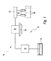
- an internal combustion engine carries the total Reference numeral 10. It includes a fuel system 12.
- the fuel system 12 consists inter alia of a Fuel tank 14, from which an electrically driven Pre-feed pump 16 the fuel to a high-pressure piston pump 18 promotes. This is to a cylinder head 20th the internal combustion engine 10 grown.
- the high pressure piston pump 18 is not shown in detail in Figure 1 Way of a camshaft (not shown) driven, which in turn with the camshaft (also not shown) of the internal combustion engine 10 is coupled.
- the high-pressure piston pump 18 compresses the supplied to her Fuel and pump it into a fuel rail 22, where the fuel is under very high pressure is stored.
- a fuel rail 22 To the fuel rail 22 are several fuel injectors 24 are connected, the combustion chambers directly associated with the fuel Inject 26.
- FIG. 2 shows:
- the high-pressure piston pump 18 comprises a housing 28, which is a fuel guide member 30 and a Cylinder sleeve 32 includes.
- a housing 28 which is a fuel guide member 30 and a Cylinder sleeve 32 includes.
- On the fuel guide part 30 are an inlet port 34, an outlet 36, and a pressure damper 38 attached.
- the cylinder liner 32 In the cylinder liner 32 is in a guide bore 39, a piston 40 slidably guided, It thus forms a guide section for the piston 40.
- the cylinder liner 32 is in a stepped blind bore 42 used in the fuel guide member 30 and on Fuel guide member 30 by means of a retaining ring 44th established.
- an adapter part 46 made of plastic used in a region of the blind bore 42 is coaxial with Cylinder sleeve 32 an adapter part 46 made of plastic used. This engages in an opening 48 in Cylinder head 20 of the internal combustion engine 10 a.
- the Adapter part 46 is thus the connection of the Fuel guide member 30 to the cylinder head 20 of the Internal combustion engine 10 produced.
- the seal between the adapter part 46 and the fuel guide part 30 done by an O-ring 50, those between the Adapter part 46 and the cylinder head 20 via an O-ring 52.
- the high pressure piston pump 18 is on the cylinder head 20th via a flange ring 54 and corresponding screws (without Reference numeral) attached.
- the fuel guide member 30 and the adapter part 46 is formed so that in the installation position of the high-pressure piston pump shown in Figure 2 18 between the fuel guide member 30 and the cylinder head 20 of the engine 10 still a there is little gap. This is in the present embodiment 0.1 mm. This will ensures that the power flow in the installation position on the Adapter part 46 extends to the cylinder head 20.
- An upper end portion 56 of the piston 40 protrudes into a Working space 58 into which fluidly with the Inlet port 34 and the outlet port 36 communicate can.
- an annular groove 60 present, in which a snap ring 62 is inserted.
- an annular groove 66 present, but which clearly is deeper than the annular groove 60.
- this annular groove 66 is of the side of a support plate 68 is inserted. This is the support disk 68 on one side with a slot 70th Mistake. Its width corresponds approximately to the diameter the annular groove 66. This relationship is from the bottom Part of the figure 2 section through the piston 40th to recognize well at the height of the support plate 68.
- a spring plate 69 On the support plate 68 is a spring plate 69. Of the Spring plate 69 is a pot-shaped component with a closed edge 71; that is contrary to the support disk 68 no slot. Between the edge 71 of the spring plate 68 and the adapter part 46 is a Piston spring 72 braced. Due to the fact that the spring plate 69 cup-shaped and he has no slot he is very resilient, especially in the axial direction, so that he the 72 initiated by the piston spring forces always safe and reliable.
- the spring plate 69 has a central bore 75, whose diameter D B is slightly larger than the diameter of the piston 40 above the annular groove 66. As a result, the spring plate 69 is centered in the installed state by the piston 40.
- An inner diameter D i of the cup-shaped spring plate 69 is dimensioned such that it centers the support plate 68. This ensures that the support disk 68 can not migrate out of the annular groove 66 in the assembled state. In addition, the inner diameter D i causes the support plate 68 can not expand radially even under the greatest load, which would lead to a loss of functionality of the high-pressure piston pump 18. Finally, it is always ensured by the construction according to the invention that the spring force of the piston spring 72 always acts centrally on the piston 40.
- the high-pressure piston pump 18 is as follows pre-assembled:
- the snap ring 62 in the annular groove 60 of Piston 40 inserted.
- the piston 40 with the End portion 64 is inserted into the cylinder liner 32 in advance.
- 64 insertion chamfers (bevels) are provided at the end region.
- 73a and 73b turned on.
- the cylinder liner 32 in the blind bore 42 is pressed in the fuel guide part 30 and by means of the retaining ring 44 on the fuel guide part 30th welded.
- the adapter part 46 is used and the piston spring 72 on the adapter part 46 and coaxial with the piston 40 arranged.
- the bias of the piston spring 72 is not effected by illustrated sideshifter.
- the piston spring 72 was released, so that these on the spring plate 69 rests, the side sliders can be easily removed, because the spring force of the piston spring 72 is no longer on it acts.
- the piston spring 72 now pushes the piston 40 from the Working space 58 out until the snap ring 62 at the Cylinder sleeve 32 comes into contact.
- the piston 40 are not moved out of the working space 58, since the Outer diameter of the snap ring 62 is greater than that Inner diameter of the guide bore 39 of the cylinder liner 32.
- the snap ring 62 thus forms a backup section in the sense of a "captive" for the piston 40th
- the force of the piston spring 72 is also the adapter part 46 so reliable against the Fuel guide member 30 pressed that the O-ring 50th can not slip.
- the high pressure fuel pump 18 operates as follows:
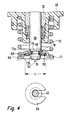
- the support disk 68 has at its outer diameter a rounded collar 80, which is used to center the Spring plate 69 is used. This means that the Center bore 75 of the spring plate 69 not for centering is needed.
Landscapes
- Engineering & Computer Science (AREA)
- Mechanical Engineering (AREA)
- General Engineering & Computer Science (AREA)
- Chemical & Material Sciences (AREA)
- Combustion & Propulsion (AREA)
- Fuel-Injection Apparatus (AREA)
- Details Of Reciprocating Pumps (AREA)
Abstract
Description
- Figur 1
- eine schematische Darstellung einer Brennkraftmaschine mit einem Kraftstoffsystem, welches eine Kolben-Kolbenpumpe umfasst;
- Figur 2
- einen teilweisen Schnitt durch die Hochdruck-Kolbenpumpe von Figur 1;
- Figur 3
- ein Detail III-III von Figur 2 und
- Figur 4
- einen Bereich einer alternativen Ausführungsform der Hochdruck-Kolbenpumpe von Figur 2.
Claims (8)
- Kolbenpumpe (18), insbesondere Hochdruck-Kraftstoffpumpe, mit einem Gehäuse (28) und mit einem in einem Führungsabschnitt (32) des Gehäuses (28) geführten Kolben (40), der mit einem Endbereich (56) in einen Arbeitsraum (58) hineinragt, wobei sich eine Kolbenfeder (72) an einem Federteller (69) abstützt, und wobei sich der Federteller (69) in axialer Richtung an dem Kolben (40) abstützt, dadurch gekennzeichnet, dass sich der Federteller (69) in axialer Richtung an einer Stützscheibe (68) abstützt, und dass die Stützscheibe (68) in eine Ringnut (66) in der Mantelfläche des Kolbens (40) eingreift.
- Kolbenpumpe (18) nach Anspruch 1, dadurch gekennzeichnet, dass sich der Federteller (69) in radialer Richtung an dem Kolben (40) abstützt.
- Kolbenpumpe (18) nach Anspruch 2, dadurch gekennzeichnet, dass der Federteller (69) eine Mittenbohrung (75) aufweist, und dass sich der Federteller (69) über die Mittenbohrung (75) in radialer Richtung an dem Kolben (40) abstützt.
- Kolbenpumpe (18) nach Anspruch 1, dadurch gekennzeichnet, dass sich der Federteller (69) in radialer Richtung an der Stützscheibe (68) abstützt.
- Kolbenpumpe (18) nach Anspruch 4, dadurch gekennzeichnet, dass die Stützscheibe (68) einen Kragen (80) aufweist, und dass die Stützscheibe (68) mit dem Kragen (80), insbesondere mit einem abgerundeten Kragen (80), den Federteller (69) radial an einem Innendurchmesser (Di) abstützt.
- Kolbenpumpe (18) nach einem der vorhergehenden Ansprüche, dadurch gekennzeichnet, dass die der Kolbenfeder (72) abgewandte Kante (76) der Ringnut (66) abgerundet ist, dass eine mit der Kante (76) zusammenwirkende Auflagefläche (78) der Stützscheibe (68) hierzu komplementär, insbesondere ballig oder kugelig, ausgebildet ist.
- Kolbenpumpe (18) nach einem der vorhergehenden Ansprüche, dadurch gekennzeichnet, dass mindestens ein Ende des Kolbens (40) einen konischen Einführabschnitt (73, 78) aufweist.
- Kolbenpumpe (18) nach einem der vorhergehenden Ansprüche, dadurch gekennzeichnet, dass sich ein von der Stützscheibe (68) abgewandtes Ende der Kolbenfeder (72) an einem Adapterteil (46) abstützt.
Applications Claiming Priority (2)
| Application Number | Priority Date | Filing Date | Title |
|---|---|---|---|
| DE10344459 | 2003-09-25 | ||
| DE2003144459 DE10344459B4 (de) | 2003-09-25 | 2003-09-25 | Kolbenpumpe, insbesondere Hochdruck-Kolbenpumpe |
Publications (2)
| Publication Number | Publication Date |
|---|---|
| EP1519033A2 true EP1519033A2 (de) | 2005-03-30 |
| EP1519033A3 EP1519033A3 (de) | 2006-05-17 |
Family
ID=34177938
Family Applications (1)
| Application Number | Title | Priority Date | Filing Date |
|---|---|---|---|
| EP04104464A Withdrawn EP1519033A3 (de) | 2003-09-25 | 2004-09-15 | Kolbenpumpe, insbesondere Hochdruck-Kolbenpumpe |
Country Status (2)
| Country | Link |
|---|---|
| EP (1) | EP1519033A3 (de) |
| DE (1) | DE10344459B4 (de) |
Cited By (11)
| Publication number | Priority date | Publication date | Assignee | Title |
|---|---|---|---|---|
| WO2010050569A1 (ja) | 2008-10-30 | 2010-05-06 | 日立オートモティブシステムズ株式会社 | 高圧燃料供給ポンプ |
| DE102009027576A1 (de) | 2009-07-09 | 2011-01-13 | Robert Bosch Gmbh | Kraftstoffhochdruckpumpe |
| DE102009027689A1 (de) | 2009-07-14 | 2011-01-20 | Robert Bosch Gmbh | Kraftstoffhochdruckpumpe |
| DE102009027937A1 (de) | 2009-07-22 | 2011-01-27 | Robert Bosch Gmbh | Kraftstoffhochdruckpumpe |
| WO2012019881A1 (de) * | 2010-08-10 | 2012-02-16 | Robert Bosch Gmbh | Geräuschoptimierte hochdruckpumpe |
| ITMI20110976A1 (it) * | 2011-05-30 | 2012-12-01 | Bosch Gmbh Robert | Gruppo di pompaggio per alimentare combustibile, preferibilmente gasolio, ad un motore a combustione interna |
| ITMI20120270A1 (it) * | 2012-02-23 | 2013-08-24 | Bosch Gmbh Robert | Pompa di alta pressione per alimentare combustibile ad un motore a combustione interna |
| WO2014170105A1 (de) * | 2013-04-17 | 2014-10-23 | Robert Bosch Gmbh | Kolbenpumpe, insbesondere kraftstoff-hochdruckpumpe |
| CN106014736A (zh) * | 2011-11-30 | 2016-10-12 | 日立汽车系统株式会社 | 高压燃料供给泵 |
| EP3153702A1 (de) * | 2015-10-05 | 2017-04-12 | Delphi International Operations Luxembourg S.à r.l. | Pumpanordnung |
| KR20170040760A (ko) * | 2015-10-05 | 2017-04-13 | 델피 인터내셔널 오퍼레이션즈 룩셈부르크 에스.에이 알.엘. | 펌핑 조립체 |
Families Citing this family (3)
| Publication number | Priority date | Publication date | Assignee | Title |
|---|---|---|---|---|
| DE102010038468A1 (de) * | 2010-07-27 | 2012-02-02 | Robert Bosch Gmbh | Hochdruckpumpe |
| DE102013200548A1 (de) * | 2013-01-16 | 2014-07-17 | Continental Teves Ag & Co. Ohg | Kolbenpumpe |
| DE102013219712B4 (de) * | 2013-09-30 | 2020-04-23 | Continental Automotive Gmbh | Dämpfer mit Stützring für eine Dichtung |
Family Cites Families (8)
| Publication number | Priority date | Publication date | Assignee | Title |
|---|---|---|---|---|
| DE1453626B2 (de) * | 1964-11-03 | 1974-12-12 | G.L. Rexroth Gmbh, 8770 Lohr | Ventil mit einem plattenförmigen Ventilglied |
| DE3201011A1 (de) * | 1982-01-15 | 1983-07-28 | Robert Bosch Gmbh, 7000 Stuttgart | Brennstoff-einspritzpumpe |
| EP1477665B1 (de) * | 1999-02-09 | 2008-04-23 | Hitachi, Ltd. | Hochdruckbrennstoffpumpe für eine Brennkraftmaschine |
| EP1415092A1 (de) * | 2001-08-08 | 2004-05-06 | CRT Common Rail Technologies AG | Hochdruckförderpumpe |
| DE10147981A1 (de) * | 2001-09-28 | 2003-04-24 | Siemens Ag | Verbindungselement zur Verbindung eines Kolbens mit einem Rückstellelement |
| US6607149B2 (en) * | 2001-12-28 | 2003-08-19 | Robert Bosch Fuel Systems Corporation | Follower assembly with retainer clip for unit injector |
| DE10200792A1 (de) * | 2002-01-11 | 2003-07-31 | Bosch Gmbh Robert | Kraftstoffpumpe für eine Brennkraftmaschine |
| DE10322597A1 (de) * | 2003-05-20 | 2004-12-09 | Robert Bosch Gmbh | Kolbenpumpe, insbesondere Hochdruck-Kraftstoffpumpe, sowie Verfahren zu deren Herstellung |
-
2003
- 2003-09-25 DE DE2003144459 patent/DE10344459B4/de not_active Expired - Lifetime
-
2004
- 2004-09-15 EP EP04104464A patent/EP1519033A3/de not_active Withdrawn
Cited By (22)
| Publication number | Priority date | Publication date | Assignee | Title |
|---|---|---|---|---|
| US9410519B2 (en) | 2008-10-30 | 2016-08-09 | Hitachi Automotive Systems, Ltd. | High-pressure fuel pump assembly mechanism |
| CN102197212A (zh) * | 2008-10-30 | 2011-09-21 | 日立汽车系统株式会社 | 高压燃料供给泵 |
| US20110253109A1 (en) * | 2008-10-30 | 2011-10-20 | Hitachi Automotive Systems Ltd | High-Pressure Fuel Pump |
| EP2341237A4 (de) * | 2008-10-30 | 2017-05-17 | Hitachi Automotive Systems, Ltd. | Hochdruckbrennstoffpumpe |
| JP2010106740A (ja) * | 2008-10-30 | 2010-05-13 | Hitachi Automotive Systems Ltd | 高圧燃料供給ポンプ |
| WO2010050569A1 (ja) | 2008-10-30 | 2010-05-06 | 日立オートモティブシステムズ株式会社 | 高圧燃料供給ポンプ |
| DE102009027576A1 (de) | 2009-07-09 | 2011-01-13 | Robert Bosch Gmbh | Kraftstoffhochdruckpumpe |
| DE102009027689A1 (de) | 2009-07-14 | 2011-01-20 | Robert Bosch Gmbh | Kraftstoffhochdruckpumpe |
| DE102009027937A1 (de) | 2009-07-22 | 2011-01-27 | Robert Bosch Gmbh | Kraftstoffhochdruckpumpe |
| WO2012019881A1 (de) * | 2010-08-10 | 2012-02-16 | Robert Bosch Gmbh | Geräuschoptimierte hochdruckpumpe |
| WO2012163576A1 (en) * | 2011-05-30 | 2012-12-06 | Robert Bosch Gmbh | Pump unit for supplying fuel, preferably diesel oil, to an internal combustion engine |
| ITMI20110976A1 (it) * | 2011-05-30 | 2012-12-01 | Bosch Gmbh Robert | Gruppo di pompaggio per alimentare combustibile, preferibilmente gasolio, ad un motore a combustione interna |
| CN106014736A (zh) * | 2011-11-30 | 2016-10-12 | 日立汽车系统株式会社 | 高压燃料供给泵 |
| CN106014736B (zh) * | 2011-11-30 | 2019-04-09 | 日立汽车系统株式会社 | 高压燃料供给泵 |
| WO2013124097A1 (en) * | 2012-02-23 | 2013-08-29 | Robert Bosch Gmbh | High - pressure pump for supplying fuel to an internal combustion engine |
| ITMI20120270A1 (it) * | 2012-02-23 | 2013-08-24 | Bosch Gmbh Robert | Pompa di alta pressione per alimentare combustibile ad un motore a combustione interna |
| CN105121831A (zh) * | 2013-04-17 | 2015-12-02 | 罗伯特·博世有限公司 | 活塞泵、特别是燃料高压泵 |
| JP2016515681A (ja) * | 2013-04-17 | 2016-05-30 | ローベルト ボツシユ ゲゼルシヤフト ミツト ベシユレンクテル ハフツングRobert Bosch Gmbh | ピストンポンプ、特に高圧燃料ポンプ |
| WO2014170105A1 (de) * | 2013-04-17 | 2014-10-23 | Robert Bosch Gmbh | Kolbenpumpe, insbesondere kraftstoff-hochdruckpumpe |
| EP3153702A1 (de) * | 2015-10-05 | 2017-04-12 | Delphi International Operations Luxembourg S.à r.l. | Pumpanordnung |
| KR20170040760A (ko) * | 2015-10-05 | 2017-04-13 | 델피 인터내셔널 오퍼레이션즈 룩셈부르크 에스.에이 알.엘. | 펌핑 조립체 |
| KR20170040758A (ko) * | 2015-10-05 | 2017-04-13 | 델피 인터내셔널 오퍼레이션즈 룩셈부르크 에스.에이 알.엘. | 펌핑 조립체 |
Also Published As
| Publication number | Publication date |
|---|---|
| DE10344459B4 (de) | 2012-06-14 |
| EP1519033A3 (de) | 2006-05-17 |
| DE10344459A1 (de) | 2005-04-14 |
Similar Documents
| Publication | Publication Date | Title |
|---|---|---|
| DE102004063074B4 (de) | Kolbenpumpe, insbesondere Kraftstoff-Hochdruckpumpe für eine Brennkraftmaschine | |
| EP1101035B1 (de) | Kolbenpumpe | |
| EP1834089B1 (de) | Kolbenpumpe, insbesondere kraftstoff-hochdruckpumpe für eine brennkraftmaschine | |
| EP1931875B1 (de) | Hochdruckpumpe, insbesondere für eine kraftstoffeinspritzeinrichtung einer brennkraftmaschine | |
| EP2013469B1 (de) | Kraftstoff-hochdruckpumpe | |
| EP1989436B1 (de) | Kraftstoffeinspritzvorrichtung für eine brennkraftmaschine | |
| DE10344459B4 (de) | Kolbenpumpe, insbesondere Hochdruck-Kolbenpumpe | |
| WO2005090790A1 (de) | Hochdruckpumpe, insbesondere für eine kraftstoffeinspritzeinrichtung einer brennkraftmaschine | |
| EP2616682B1 (de) | Verfahren zur herstellung einer kolbenpumpe und kolbenpumpe | |
| DE102009000859A1 (de) | Kraftstoffhochdruckpumpe | |
| EP2409014B1 (de) | HOCHDRUCKPUMPE UND STÖßELBAUGRUPPE | |
| DE10020867B4 (de) | Common-Rail-Injektor | |
| EP1561028B1 (de) | Kraftstoffhochdruckpumpe mit kugelventil im niederdruck-einlass | |
| DE10322603B4 (de) | Kolbenpumpe, insbesondere Hochdruck-Kolbenpumpe für Brennkraftmaschinen mit Direkteinspritzung | |
| DE69915946T2 (de) | Dichtung | |
| DE10134069B4 (de) | Kraftstoffpumpe für ein Kraftstoffsystem einer Brennkraftmaschine | |
| EP2449261A1 (de) | Hochdruckpumpe | |
| EP1319831A2 (de) | Kraftstoffhochdruckpumpe mit integrierter Sperrflügel-Vorförderpumpe | |
| DE102020214037A1 (de) | Kraftstoff-Hochdruckpumpe | |
| DE102009001633A1 (de) | Hochdruckpumpe und Stößelbaugruppe | |
| DE10352024A1 (de) | Elektromagnetventil | |
| EP2256332B1 (de) | Kraftstoffinjektor mit Druckverstärkerkolben | |
| EP3332111B1 (de) | Elektromagnetisch betätigbares saugventil für eine hochdruckpumpe sowie hochdruckpumpe | |
| DE3928375C2 (de) | Kolbenpumpe | |
| DE10322597A1 (de) | Kolbenpumpe, insbesondere Hochdruck-Kraftstoffpumpe, sowie Verfahren zu deren Herstellung |
Legal Events
| Date | Code | Title | Description |
|---|---|---|---|
| PUAI | Public reference made under article 153(3) epc to a published international application that has entered the european phase |
Free format text: ORIGINAL CODE: 0009012 |
|
| AK | Designated contracting states |
Kind code of ref document: A2 Designated state(s): AT BE BG CH CY CZ DE DK EE ES FI FR GB GR HU IE IT LI LU MC NL PL PT RO SE SI SK TR |
|
| AX | Request for extension of the european patent |
Extension state: AL HR LT LV MK |
|
| PUAL | Search report despatched |
Free format text: ORIGINAL CODE: 0009013 |
|
| AK | Designated contracting states |
Kind code of ref document: A3 Designated state(s): AT BE BG CH CY CZ DE DK EE ES FI FR GB GR HU IE IT LI LU MC NL PL PT RO SE SI SK TR |
|
| AX | Request for extension of the european patent |
Extension state: AL HR LT LV MK |
|
| AKX | Designation fees paid | ||
| STAA | Information on the status of an ep patent application or granted ep patent |
Free format text: STATUS: THE APPLICATION IS DEEMED TO BE WITHDRAWN |
|
| 18D | Application deemed to be withdrawn |
Effective date: 20061118 |
|
| REG | Reference to a national code |
Ref country code: DE Ref legal event code: 8566 |