EP2341237B1 - Pump for supplying high-pressure fuel - Google Patents
Pump for supplying high-pressure fuel Download PDFInfo
- Publication number
- EP2341237B1 EP2341237B1 EP09823679.7A EP09823679A EP2341237B1 EP 2341237 B1 EP2341237 B1 EP 2341237B1 EP 09823679 A EP09823679 A EP 09823679A EP 2341237 B1 EP2341237 B1 EP 2341237B1
- Authority
- EP
- European Patent Office
- Prior art keywords
- cylinder
- pump housing
- plunger
- pressure fuel
- pressurizing chamber
- Prior art date
- Legal status (The legal status is an assumption and is not a legal conclusion. Google has not performed a legal analysis and makes no representation as to the accuracy of the status listed.)
- Active
Links
Images


Classifications
-
- F—MECHANICAL ENGINEERING; LIGHTING; HEATING; WEAPONS; BLASTING
- F02—COMBUSTION ENGINES; HOT-GAS OR COMBUSTION-PRODUCT ENGINE PLANTS
- F02M—SUPPLYING COMBUSTION ENGINES IN GENERAL WITH COMBUSTIBLE MIXTURES OR CONSTITUENTS THEREOF
- F02M59/00—Pumps specially adapted for fuel-injection and not provided for in groups F02M39/00 -F02M57/00, e.g. rotary cylinder-block type of pumps
- F02M59/44—Details, components parts, or accessories not provided for in, or of interest apart from, the apparatus of groups F02M59/02 - F02M59/42; Pumps having transducers, e.g. to measure displacement of pump rack or piston
-
- F—MECHANICAL ENGINEERING; LIGHTING; HEATING; WEAPONS; BLASTING
- F02—COMBUSTION ENGINES; HOT-GAS OR COMBUSTION-PRODUCT ENGINE PLANTS
- F02M—SUPPLYING COMBUSTION ENGINES IN GENERAL WITH COMBUSTIBLE MIXTURES OR CONSTITUENTS THEREOF
- F02M39/00—Arrangements of fuel-injection apparatus with respect to engines; Pump drives adapted to such arrangements
- F02M39/02—Arrangements of fuel-injection apparatus to facilitate the driving of pumps; Arrangements of fuel-injection pumps; Pump drives
-
- F—MECHANICAL ENGINEERING; LIGHTING; HEATING; WEAPONS; BLASTING
- F04—POSITIVE - DISPLACEMENT MACHINES FOR LIQUIDS; PUMPS FOR LIQUIDS OR ELASTIC FLUIDS
- F04B—POSITIVE-DISPLACEMENT MACHINES FOR LIQUIDS; PUMPS
- F04B1/00—Multi-cylinder machines or pumps characterised by number or arrangement of cylinders
- F04B1/04—Multi-cylinder machines or pumps characterised by number or arrangement of cylinders having cylinders in star- or fan-arrangement
- F04B1/0404—Details or component parts
- F04B1/0408—Pistons
-
- F—MECHANICAL ENGINEERING; LIGHTING; HEATING; WEAPONS; BLASTING
- F04—POSITIVE - DISPLACEMENT MACHINES FOR LIQUIDS; PUMPS FOR LIQUIDS OR ELASTIC FLUIDS
- F04B—POSITIVE-DISPLACEMENT MACHINES FOR LIQUIDS; PUMPS
- F04B1/00—Multi-cylinder machines or pumps characterised by number or arrangement of cylinders
- F04B1/04—Multi-cylinder machines or pumps characterised by number or arrangement of cylinders having cylinders in star- or fan-arrangement
- F04B1/0404—Details or component parts
- F04B1/0421—Cylinders
-
- F—MECHANICAL ENGINEERING; LIGHTING; HEATING; WEAPONS; BLASTING
- F04—POSITIVE - DISPLACEMENT MACHINES FOR LIQUIDS; PUMPS FOR LIQUIDS OR ELASTIC FLUIDS
- F04B—POSITIVE-DISPLACEMENT MACHINES FOR LIQUIDS; PUMPS
- F04B1/00—Multi-cylinder machines or pumps characterised by number or arrangement of cylinders
- F04B1/04—Multi-cylinder machines or pumps characterised by number or arrangement of cylinders having cylinders in star- or fan-arrangement
- F04B1/0404—Details or component parts
- F04B1/0439—Supporting or guiding means for the pistons
-
- F—MECHANICAL ENGINEERING; LIGHTING; HEATING; WEAPONS; BLASTING
- F04—POSITIVE - DISPLACEMENT MACHINES FOR LIQUIDS; PUMPS FOR LIQUIDS OR ELASTIC FLUIDS
- F04B—POSITIVE-DISPLACEMENT MACHINES FOR LIQUIDS; PUMPS
- F04B53/00—Component parts, details or accessories not provided for in, or of interest apart from, groups F04B1/00 - F04B23/00 or F04B39/00 - F04B47/00
- F04B53/16—Casings; Cylinders; Cylinder liners or heads; Fluid connections
- F04B53/162—Adaptations of cylinders
- F04B53/166—Cylinder liners
- F04B53/168—Mounting of cylinder liners in cylinders
-
- F—MECHANICAL ENGINEERING; LIGHTING; HEATING; WEAPONS; BLASTING
- F02—COMBUSTION ENGINES; HOT-GAS OR COMBUSTION-PRODUCT ENGINE PLANTS
- F02M—SUPPLYING COMBUSTION ENGINES IN GENERAL WITH COMBUSTIBLE MIXTURES OR CONSTITUENTS THEREOF
- F02M2200/00—Details of fuel-injection apparatus, not otherwise provided for
- F02M2200/02—Fuel-injection apparatus having means for reducing wear
-
- F—MECHANICAL ENGINEERING; LIGHTING; HEATING; WEAPONS; BLASTING
- F02—COMBUSTION ENGINES; HOT-GAS OR COMBUSTION-PRODUCT ENGINE PLANTS
- F02M—SUPPLYING COMBUSTION ENGINES IN GENERAL WITH COMBUSTIBLE MIXTURES OR CONSTITUENTS THEREOF
- F02M2200/00—Details of fuel-injection apparatus, not otherwise provided for
- F02M2200/85—Mounting of fuel injection apparatus
-
- F—MECHANICAL ENGINEERING; LIGHTING; HEATING; WEAPONS; BLASTING
- F02—COMBUSTION ENGINES; HOT-GAS OR COMBUSTION-PRODUCT ENGINE PLANTS
- F02M—SUPPLYING COMBUSTION ENGINES IN GENERAL WITH COMBUSTIBLE MIXTURES OR CONSTITUENTS THEREOF
- F02M59/00—Pumps specially adapted for fuel-injection and not provided for in groups F02M39/00 -F02M57/00, e.g. rotary cylinder-block type of pumps
- F02M59/02—Pumps specially adapted for fuel-injection and not provided for in groups F02M39/00 -F02M57/00, e.g. rotary cylinder-block type of pumps of reciprocating-piston or reciprocating-cylinder type
- F02M59/10—Pumps specially adapted for fuel-injection and not provided for in groups F02M39/00 -F02M57/00, e.g. rotary cylinder-block type of pumps of reciprocating-piston or reciprocating-cylinder type characterised by the piston-drive
- F02M59/102—Mechanical drive, e.g. tappets or cams
-
- F—MECHANICAL ENGINEERING; LIGHTING; HEATING; WEAPONS; BLASTING
- F02—COMBUSTION ENGINES; HOT-GAS OR COMBUSTION-PRODUCT ENGINE PLANTS
- F02M—SUPPLYING COMBUSTION ENGINES IN GENERAL WITH COMBUSTIBLE MIXTURES OR CONSTITUENTS THEREOF
- F02M59/00—Pumps specially adapted for fuel-injection and not provided for in groups F02M39/00 -F02M57/00, e.g. rotary cylinder-block type of pumps
- F02M59/20—Varying fuel delivery in quantity or timing
- F02M59/36—Varying fuel delivery in quantity or timing by variably-timed valves controlling fuel passages to pumping elements or overflow passages
- F02M59/366—Valves being actuated electrically
Definitions
- the present invention relates to a high-pressure fuel pump for an internal combustion engine assembled to an engine block of the engine, and in particular to its assembly mechanism.
- a holder (46) having an external cylindrical surface portion (46) fitted to a mounting hole (48) formed in an engine is configured such that a plunger seal member is held by an internal cylindrical surface portion of the holder (46).
- Patent Document 2 relates to a fluid pump, wherein a cylinder supporting a plunger and a pump housing are formed with dissimilar metals and a pressing mechanism to press the cylinder and the pump housing relatively to each other is provided so that a pressurizing chamber is sealed through a pressing surface between the pump housing and the cylinder.
- Patent Document 3 relates to a high pressure fuel pump for an internal combustion engine having a cylinder 20, a plunger 2 slidably fitted in the cylinder 20 and a seal mechanism for blocking fuel leakage from an end of a sliding portion between the cylinder 20 and the plunger 2 and also for preventing a lubricant for a driving mechanism of the plunger 2 from entering into the cylinder 20 from the end of the sliding portion of the cylinder 20 and the plunger 2.
- a high-pressure fuel pump of the present invention is provided with a holder including an outer cylindrical surface portion fitted to a high-pressure fuel pump attachment fitting hole provided in an engine block of an internal combustion engine and including a cylindrical fitting portion fitted to an outer circumference of the cylinder of the pump.
- the holder is configured such that the outer cylindrical surface portion and the cylindrical fitting portion are formed in a single piece resulting from machining one and the same member.
- a high-pressure fuel pump comprises: a pump housing formed with a recess; a cylinder combined with the pump housing to define the recess as an pressurizing chamber; a holder securing the cylinder to the pump housing; a plunger sliding against the cylinder to pressurize fluid in the pressurizing chamber; wherein reciprocation of the plunger pressurizes fuel sucked in the pressurizing chamber and discharges the fuel from the pressurizing chamber; and wherein the holder includes an outer cylindrical surface portion fitted to an attachment fitting hole of an engine block of an internal combustion engine, the holder is provided with a cylindrical fitting portion fitted to an outer circumference of the cylinder, the outer cylindrical surface portion and the cylindrical fitting portion are formed in a single piece resulting from machining one and the same member, and an outer circumferential surface of the cylinder projecting into the pressurizing chamber and an inner circumferential surface of the pump housing defining the pressurizing chamber are configured so as not to contact each other as a clearance is provided between the outer circumferential surface
- the outer cylindrical surface portion and the cylinder fitting portion are formed of respective cylindrical surfaces, axial centers of the cylindrical surfaces coinciding with the central axis of the plunger insertion hole formed in the cylinder.
- the cylinder is subjected to pressure contact with the pump housing, at this pressure contact portion, a seal portion resulting from metal contact is formed to thus define the pressurizing chamber, and the holder is configured to function as securing means for bringing the cylinder and the pump housing into pressure contact with each other.
- a second seal member forming a seal portion in cooperation with the inner circumferential surface of the attachment fitting hole of the engine block is attached to the outer cylindrical surface portion of the holder.
- the high-pressure fuel pump further comprises: a seal member attached to an outer circumferential surface of the plunger, the outer circumferential surface being located on a side opposite the pressurizing chamber, wherein the holder is provided with an inner cylindrical surface portion into which the seal member is housed.
- the outer cylindrical surface portion, the inner cylindrical surface portion and the cylindrical fitting portion are formed in a single piece resulting from machining one and the same member.
- the outer cylindrical surface portion, the inner cylindrical surface portion and the cylindrical fitting portion are formed to have the same axial center.
- a third seal member is installed between the outer circumferential surface of the holder and the pump housing.
- the seal portion resulting from the metal contact is formed of the metal contact portion between the pump housing and the cylinder to define the pressurizing portion, the seal member is attached to the outer circumference of the plunger extending outwardly from a sliding portion between the cylinder and the piston plunger, and the seal member is secured to the inner cylindrical surface portion of the holder.
- the plunger is configured to be able to advance into and retreat from the inside of the pressurizing chamber formed in the pump housing beyond the distal end of the cylinder.
- the metal contact seal portion is formed by bringing the pump housing and the cylinder into pressure contact with each other at a plane crossing the movement direction of the plunger, and a pressing mechanism is provided, the pressing mechanism relatively pressing the pump housing and the cylinder toward the metal contact seal portion.
- the pressing mechanism is composed of a screw portion formed on the outer circumference of the holder and a second screw portion formed on the pump housing so as to be threadedly engaged with the screw portion.
- the high-pressure fuel pump further comprises: securing means for securing the pump housing to the engine block of the internal combustion engine.
- a high-pressure fuel pump comprises: a pump housing formed with a recess; a cylinder combined with the pump housing to define the recess as a pressurizing chamber; and a plunger sliding against the cylinder to pressurize fluid in the pressurizing chamber; wherein reciprocation of the plunger pressurizes fuel sucked into the pressurizing chamber and discharges the fuel from the pressurizing chamber; wherein the high-pressure fuel pump includes: a seal member attached to an outer circumferential surface of the piston plunger, the outer circumferential surface being located on a side opposite the pressurizing chamber; and a holder housing the seal member; wherein the holder includes an outer cylindrical surface portion fitted to an attachment fitting hole of an engine block of an internal combustion engine, and an inner cylindrical surface portion housing the seal member; and wherein the holder is provided with a cylindrical fitting portion fitted to an outer circumference of the cylinder, the outer cylindrical surface portion, the inner cylindrical surface portion and the cylindrical fitting portion are formed in a single piece
- the outer cylindrical surface portion, the inner cylindrical surface portion and the cylindrical fitting portion are formed of respective cylindrical surfaces, axial centers of the cylindrical surfaces coinciding with a central axis of the plunger insertion hole formed in the cylinder.
- a high-pressure fuel pump comprises: a pump housing formed with a recess; a cylinder combined with the pump housing to define the recess as a pressurizing chamber; a plunger sliding against the cylinder to pressurize fluid in the pressurizing chamber; wherein reciprocation of the plunger pressurizes fuel sucked into the pressurizing chamber and discharges the fuel from the pressurizing chamber; wherein the high-pressure pump includes a seal member attached to an outer circumferential surface of the piston plunger, the outer circumferential surface being located on a side opposite the pressurizing chamber; and a holder housing the seal member; wherein the holder includes an outer cylindrical surface portion fitted to an attachment fitting hole of an engine block of an internal combustion engine, and an inner cylindrical surface portion housing the seal member; and wherein the outer cylindrical surface portion and the inner cylindrical surface portion are formed of respective cylindrical surfaces, axial centers of the cylindrical surfaces coinciding with a central axis of an insertion hole of the piston plunger formed in the
- the high-pressure fuel pump of the present invention is configured as described above. Therefore, the central axis of the insertion hole of the piston plunger installed in the cylinder easily provides coaxiality with respect to the central axis of the attachment fitting hole installed in the engine block of the internal combustion engine. Biting and wear between the cylinder and the piston plunger caused by the side force applied to the piston plunger by a drive mechanism can be reduced.
- a basic configuration of an embodiment of the present invention is as described below.
- the parenthetic symbols denote reference numerals of portions relating to the embodiment just for reference.
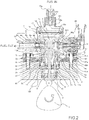
- a pump housing (1) is formed with a bottomed recess (1A) at a central portion thereof.
- a tubular cylinder (6) is combined with an inner circumferential cylindrical portion of the recess (1A) on the opening end side thereof to define the recess (1A) as a pressurizing chamber (11).
- a piston plunger sliding with respect to the cylinder (6) and pressurizing the fluid in the pressurizing chamber (11) reciprocates to suck fuel into the pressurizing chamber (11).
- the fuel pressurized in the pressurizing chamber (11) is discharged from a discharge port (12) via a discharge valve unit (8).
- a cylinder holder (7) includes an outer cylindrical surface portion (7b) fitted to an attachment fitting hole (70) of an engine block (100) of an internal combustion engine. Further, the cylinder holder (7) includes a cylindrical fitting portion (7a) fitted to the outer circumference of the cylinder (6). The outer cylindrical surface portion (7b) and the cylindrical fitting portion (7a) are formed in a single piece resulting from machining one and the same member.
- an attachment fitting hole (70) provided in the engine block (100) functions as a positioning cylindrical portion between the engine block (100) and the outer circumference of the cylinder holder (7). Therefore, the central axis of an insertion hole of the piston plunger (2) installed in the cylinder (6) easily provides coaxiality with respect to the central axis of the attachment fitting hole (70) installed in the engine block (100) of the internal combustion engine. Consequently, biting and wear caused by sliding between the cylinder (6) and the piston plunger (2), which are due to side force applied to the piston plunger (2) by a drive mechanism, can be reduced.
- the outer cylindrical surface portion (7b) and the cylinder fitting portion (7a) are each formed of a cylindrical surface whose axial center coincides with the central axis of the insertion hole of the piston plunger (2) formed in the cylinder (6).
- the cylinder (6) is brought into pressure contact with the pump housing (1).
- a seal portion (6a) resulting from metal contact is formed to thus define the pressurizing chamber (11).
- the cylinder holder (7) is configured to function as securing means for bringing the cylinder (6) and the pump housing (1) into pressure contact with each other. Circumferential pressing force resulting from press fitting can be used as the securing means for press contact. Also swaging can be used.
- a second seal member (61) forming a seal portion in cooperation with the inner circumferential surface of the attachment fitting hole (70) of the engine block (100) is attached to the outer cylindrical surface portion (7b) of the cylinder holder (7). While their axial centers are aligned with each other, the seal for each portion can be achieved.
- a seal member (13) attached to the outer circumferential surface, of the piston plunger (2), on a side opposite the pressurizing chamber (11) is provided.
- the cylinder holder (7) is provided with an inner cylindrical surface portion (7c) into which the seal member (13) is housed.
- the outer cylindrical surface portion (7b), the inner cylindrical surface portion (7c) and the cylindrical fitting portion (7a) are formed in a single piece resulting from machining one and the same member. With this configuration, their three axial centers can accurately be aligned with one another.
- the outer cylindrical surface portion (7b), the inner cylindrical surface portion (7c) and the cylindrical fitting portion (7a) are formed to have the same axial center. With this configuration, their three axial centers can accurately be aligned with one another.
- an adjusting gap respectively a clearance (1B) is provided between the inner circumferential surface of the pump housing (1) defining the pressurizing chamber (11) and the outer circumferential surface of the cylinder (6) projecting into the pressurizing chamber (11).
- a third seal member (62) is installed between the outer circumferential surface of the cylinder holder (7) and the pump housing (1), i.e., in an outer circumferential groove (7f) of the cylinder holder (7). With this configuration, the sealing between the cylinder holder (7) and the pump housing (1) can be achieved.
- the seal portion (6a) resulting from the metal contact is formed of the metal contact portion between the pump housing (1) and the cylinder (6) to define the pressurizing portion (11).
- a leakage of fuel from a portion between the cylinder (6) and the piston plunger is sealed by the seal member (13) attached to the outer circumference of the piston plunger (2) extending outwardly from a sliding portion between the cylinder (6) and the piston plunger (2).
- the seam member (13) is secured to the inner cylindrical surface portion (7c) of the cylinder holder (7).
- the piston plunger (2) is configured to be able to advance into and retreat from the inside of the pressurizing chamber formed in the pump housing (1) beyond the distal end of the cylinder (6).
- the piston plunger (2) projecting into the pressurizing chamber (11) is cooled by the fuel in the pressurizing chamber. Therefore, sliding wear at the sliding hole of the cylinder (6) can be reduced.
- the sliding portion between the cylinder (6) and the piston plunger (2) can be made close to the axial central portion of the piston plunger (2), thereby suppressing the inclination of the piston plunger (2).
- the metal contact seal portion (6a) is formed by bringing the pump housing (1) and the cylinder (6) into pressure contact with each other at a plane crossing the movement direction of the piston plunger (2).
- a pressing mechanism (the cylinder holder (7) in the embodiment) is provided that relatively presses the pump housing (1) and the cylinder (6) toward the metal contact seal portion (6a). With this configuration, the force used for the sealing can be increased to provide reliable sealing. As the pressing mechanism, the lower end of the cylinder can be subjected to swage toward the seal surface.
- the pressing mechanism (the cylinder holder (7) in the embodiment) is composed of a screw portion (7g) formed on the outer circumference of the cylinder holder (7) and a second screw portion (1b) formed on the pump housing 1 so as to be threadedly engaged with the screw portion.
- sealing force can simply be obtained by screwing the cylinder holder (7).
- securing means for securing the pump housing (1) to the engine block (100) of the internal combustion engine is provided.
- a high-pressure fuel pump includes: a pump housing (1) formed with a recess (1A); a cylinder (6) combined with the pump housing (1) to define the recess (1A) as a pressurizing chamber (11); and a piston chamber (2) sliding against the cylinder (6) to pressurize fluid in the pressurizing chamber (11), wherein reciprocation of the piston plunger (2) pressurize the fuel sucked into the pressurizing chamber (11) to discharge the fuel from the pressurizing chamber (11).
- the high-pressure fuel pump includes a seal member (13) attached to an outer circumferential surface on a side opposite the pressurizing chamber (11) of the piston plunger (2), and a holder (a cylinder holder (7) in the embodiment) housing the seal member (13), wherein the holder (the cylinder holder (7) in the embodiment) includes an outer cylindrical surface portion (7b) fitted to an attachment fitting hole (70) of an engine block (100) of an internal combustion engine, and an inner cylindrical surface portion (7c) housing the seal member (13).
- the holder (the cylinder holder (7) in the embodiment) is provided with a cylindrical fitting portion (7a) fitted to an outer circumference of the cylinder (6).
- the outer cylindrical surface portion (7b), the inner cylindrical surface portion (7c) and the cylindrical fitting portion (7a) are formed in a single piece resulting from machining one and the same member.
- the plunger seal holder and the cylinder holder are formed integrally with each other and the cylinder holder is formed with a fitting portion with the attachment fitting hole of the engine block (100). Therefore, three central axes of the above three can easily be allowed to coincide with one another.
- the outer cylindrical surface portion (7b), the inner cylindrical surface portion (7c) and the cylindrical fitting portion (7a) are formed of respective cylindrical surfaces whose axial centers coincide with a central axis of a piston plunger (2) insertion hole formed in the cylinder (6).
- the three central axes of the three can further easily be allowed to coincide with one another.
- a high-pressure fuel pump includes: a pump housing (1) formed with a recess (1A); a cylinder (6) combined with the pump housing (1) to define the recess (1A) as a pressurizing chamber (11); and a piston chamber (2) sliding against the cylinder (6) to pressurize fluid in the pressurizing chamber (11), wherein reciprocation of the piston plunger (2) pressurize the fuel sucked into the pressurizing chamber (11) to discharge the fuel from the pressurizing chamber (11).
- the high-pressure fuel pump includes: a seal member (13) attached to an outer circumferential surface on a side opposite the pressurizing chamber (11) of the piston plunger (2); and a holder (a cylinder holder (7) in the embodiment) housing the seal member (13), wherein the holder (the cylinder holder (7) in the embodiment) includes an outer cylindrical surface portion (7b) fitted to an attachment fitting hole (70) of an engine block (100) of an internal combustion engine, and an inner cylindrical surface portion (7c) housing the seal member (13), and the outer cylindrical surface portion (7b) and the inner cylindrical surface portion (7c) are formed of respective cylindrical surfaces whose axial centers coincide with a central axis of an insertion hole of the piston plunger (2) formed in the cylinder (6).
- the axial centers of the inner and outer cylindrical portions of the plunger seal holders can accurately be aligned with each other.
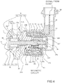
- a portion surrounded by a broken line indicates a pump housing 1 of a high-pressure pump. Mechanisms and component parts illustrated in the broken line are integrally assembled in the pump housing 1 of the high-pressure pump.
- Fuel in a fuel tank 20 is pumped up by a feed pump 21 on the basis of a signal from an engine control unit 27 (hereinafter referred to as the ECU), pressurized to an appropriate feed-pressure, and supplied to an inlet port 10a of a high-pressure fuel pump trough a suction pipe 28.
- the ECU engine control unit 27
- the fuel having passed through the inlet port 10a passes through a filter 102 secured to the inside of an inlet joint 101 and reaches an inlet port 30a of an electromagnetically-driven valve mechanism 30 constituting a capacity variable mechanism through metal diaphragm dampers 9 and 10c.
- the intake filter 102 in the inlet joint 101 has a role of preventing foreign particles existing between the fuel tank 20 and the inlet port 10a from entering the inside of the high-pressure fuel pump along with the fuel flow.
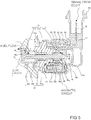
- Fig. 4 is an enlarged view of the electromagnetic inlet valve mechanism 30, illustrating a state where an electromagnetic coil 53 is not energized.
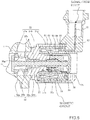
- Fig. 5 is an enlarged view of the electromagnetic inlet valve mechanism 30, illustrating a state where the electromagnetic coil 53 is energized.
- the pump housing 1 is centrally formed with a protruding portion 1A serving as a pressurizing chamber 11.
- a hole 30A adapted to receive the electromagnetic inlet valve mechanism 30 mounted thereinto is formed in the pump housing 1 so as to communicate with the pressurizing chamber 11.
- a plunger rod 31 constituting the movable plunger is composed of three portions: an inlet valve portion 31a, a rod portion 31b, and an anchor-securing portion 31c.
- the anchor 35 is fixedly welded to the anchor-securing portion 31c through a welded portion 37b.
- a spring member 34 is fitted into an anchor inner circumference 35a and into a first core portion inner circumference 33a so as to generate a spring force acting in a direction of moving the anchor 35 and the first core portion 33 away from each other.
- a valve seat member 32 is composed of an inlet valve seat portion 32a, an intake passage portion 32b, a press-fitting portion 32c, and a sliding bearing portion 32d.
- the press-fitting portion 32c is fixedly press fitted into the annular recess of one end of the first core portion 33.
- the press-fitting portion 32c is provided with a plurality of small holes 32e.
- a gap is defined between the outer circumference of the sliding bearing portion 32d and the inner circumferential surface of the first core portion 33 so as to communicate with the intake passage portion 32b through the small holes 32e, allowing for entrance and exit of fluid (fuel).
- the inlet valve seat portion 32a is fixedly press fitted into the pump housing 1 to form a press-fitting portion, which completely isolates the pressurizing chamber 11 and the inlet port 30a from each other.
- the first core portion 33 is fixedly welded to the pump housing 1 through the welded portion 37c to isolate the inlet port 30a and the outside of the high-pressure fuel pump from each other.
- the second core portion 36 is composed of a cap member made of a magnetic material and is fixedly welded at the opening end side to the first core portion 33 through the welded portion 37a.
- the second core portion 36 is provided on the outer circumferential surface with a magnetic orifice portion 36a composed of an annular groove.
- the inlet valve portion 31a is set such that the valve-opening force resulting from the fluid differential pressure opens the intake port 38, overcoming the biasing force of the spring member 34.
- the inlet valve portion 31a is fully opened and the anchor 31 comes into contact with the first core portion 33.
- the inlet valve portion 31a is not fully opened and the anchor 31 does not come into contact with the first core portion 33.
- the inlet valve portion 31a When the inlet valve portion 31a is fully opened, its opened state is maintained. On the other hand, when the inlet valve portion 31a is not fully opened, the opening movement of the inlet valve portion 31a is assisted to fully open the inlet valve portion 31a. That is to say, the anchor 31 comes into contact with the first core portion 33. Thereafter, this state is maintained.
- the intake process of the piston plunger 2 is ended while the application of the input voltage to the electromagnetic inlet valve mechanism 30 is maintained.
- the intake process is shifted to the compression process in which the piston plunger 2 is displaced upward in Fig. 2 .
- the inlet valve portion 31a remains opened.
- the capacity of the pressurizing chamber 11 is reduced along with the compressive movement of the piston chamber 2. In this state, however, the fuel sucked once into the pressurizing chamber 11 is returned to the intake passage 10c (the inlet port 30a) again through the intake port 38 that is in the opened state. Therefore, the pressure in the pressurizing chamber 11 will not rise. This process is called a return process.
- the fuel left in the pressurizing chamber 11 is discharged at high pressure through the discharge valve unit 8 to a common rail 23.
- This process is called a discharged process. That is to say, the compression process (the elevation process between lower dead center and upper dead center) by the piston plunger 2 consists of the return process and the discharge process.
- the amount of high-pressure fuel to be discharged can be controlled by controlling timing to cancel the energization of the electromagnetic coil 53 of the electromagnetic inlet valve mechanism 30.
- the return process has a small proportion whereas the discharge process has a large one.
- fuel to be returned to the intake passage 10c (the inlet port 30a) is in a small amount, whereas fuel to be discharged at high pressure is in a large amount.
- the timing to cancel the input voltage is delayed, in the compression process, the return process has a large proportion whereas the discharge process has a small one.
- fuel to be returned to the intake passage 10c is in a large amount, whereas fuel to be discharged at high pressure is in a small amount.
- the timing to cancel the energization of the electromagnetic coil 53 is controlled by an instruction from the ECU.
- controlling timing to cancel the energization of the electromagnetic coil 53 can control the amount of fuel to be discharged at high pressure to the amount necessary for the internal combustion engine.
- the fuel led through the fuel inlet port 10a to the pressurizing chamber 11 of the pump housing 1 is highly pressurized in a desired amount by the reciprocation of the piston plunger 2 and then supplied under pressure to the common rail 23 from the fuel discharge port 12.
- Injectors 24 and a pressure sensor 26 are attached to the common rail 23.
- the number of the injectors 24 thus attached is made equal to that of cylinders of the internal combustion engine.
- the injectors 24 inject fuel into the corresponding cylinders while being opened and closed.
- the inlet valve portion 31a repeats the opening and closing operations for the intake port 38, and the plunger rod 31 repeats leftward and rightward movements in the figures.
- the movement of the plunger rod 31 is limited only to the leftward and rightward movements in Figs. 4 to 6 by the sliding bearing portion 32d of the valve seat member 32.
- the sliding bearing portion 32d and the rod portion 31b repeat sliding movement therebetween. Therefore, the sliding portion needs sufficiently low surface roughness so as not to act as resistance against the sliding movement of the plunger rod 31.
- the clearance of the sliding portion is selected as below.
- the plunger rod 31 may swing around the sliding portion like a pendulum, whereby the anchor 35 and the second core portion 36 come into contact with each other. If the plunger rod 31 slidably moves, also the anchor 35 and the second core portion 36 may slide with each other, which increases resistance resulting from the sliding movement of the plunger rod 31. Thus, the responsiveness of the opening and closing movement for the intake port 38 becomes poor. Since the anchor 35 and the second core portion 36 are made of ferritic magnetic stainless steel, if they slide with each other, it is probable that wear powder and the like may be produced. As described later, the smaller the gap between the anchor 35 and the second core portion 36, the larger the magnetic biasing force.
- the sliding portion is made single and further a sliding length L of the sliding bearing portion 32d is made sufficiently long as shown in Figs. 4 and 5 .
- the sliding portion is formed of the inner diameter of the sliding bearing portion 32d and the outer diameter of the rod portion 31b. Machining any of them inevitably needs tolerance and also the clearance of the sliding portion inevitably needs tolerance.
- the clearance between the anchor 35 and the second core portion 36 has an upper limit because of the magnetic biasing force as described above. To accommodate the tolerance of the clearance and to prevent the anchor 35 and the second core portion 36 from coming into contact with each other, it is needed only to make the sliding length L longer, thereby reducing the pendulum motion.
- the inlet valve portion 31a and the inlet valve seat portion 32a will not come into full surface contact with each other. This is because the clearance of the sliding portion cannot accommodate the perpendicularity of the inlet valve portion 31a and rod portion 31b of the plunger rod 31 and that of the inlet valve seat portion 32a and sliding bearing portion 32d of the valve seat member 32. Unless the inlet valve portion 31a and the seat portion 32a come into full surface contact with each other, it is probable that the plunger rod 31 may undergo excessive torque to be damaged because of high-pressure fuel in the pressurizing chamber 11 having high pressure during the discharge process. In addition, it is probable that the sliding portion may undergo an excessive load to be damaged or worn.
- the inlet valve portion 31a and the inlet valve seat portion 32a it is necessary for the inlet valve portion 31a and the inlet valve seat portion 32a to come into full surface contact with each other in the closed state of the intake port 38.
- the increased sliding length L intends to suppress the pendulum movement of the plunger rod 31 as described above, accuracy is increased that is desired by the perpendicularity of the inlet valve portion 31a and rod portion 31b of the plunger rod 31 and that of the inlet valve seat portion 32a and sliding bearing portion 32d of the valve seat member 32.
- the inlet valve seat portion 32a and the sliding bearing portion 32d are provided on the valve seat member 32.
- the inlet valve seat portion 32a and the sliding bearing portion 32d are made of one and the same member so as to have the accurate perpendicularity. If the inlet valve seat member 32a and the sliding bearing portion 32d are made of different members each other, causes of poor perpendicularity occur at machined and joined portions. This problem can be solved by the inlet valve seat portion 32a and the sliding bearing portion 32d being made of a single member.
- the magnetic circuit formed around the electromagnetic coil 53 should be one that can generate a sufficient magnetic biasing force.
- a magnetic circuit is desired to flow much more magnetic flux when the electromagnetic coil 53 is energized to produce a magnetic field therearound.
- the thicker and shorter the magnetic circuit is the smaller magnetic resistance is. Therefore, magnetic flux passing through the magnetic circuit increases to increase a magnetic biasing force generated.
- members constituting the magnetic circuit are the anchor 35, the first core portion 33, the yoke 51, and the second core portion 36, all of which are magnetic materials.
- the first core portion 33 and the second core portion 36 are joined together by welding at the welded portion 37a.
- the magnetic flux is required not to directly pass through between the first core portion 33 and the second core portion 36 but to pass through therebetween via the anchor 35. This intends to produce the magnetic biasing force between the first core portion 33 and the anchor 35. If the magnetic flux directly passes through between the first core portion 33 and the second core portion 36 so that magnetic flux passing through the anchor 35 reduces, the magnetic biasing force decreases.
- a conventional configuration is such that an intermediate member is provided between the first core portion 33 and the second core portion 36. Since the intermediate member is a non-magnetic body, the magnetic flux will not directly pass through between the first core portion 33 and the second core portion 36 but all the magnetic flux passes through the anchor 35.
- the provision of the intermediate member increases the number of component parts and requires necessity to join the intermediate member to the first core portion 33 and to the second core portion 36, which leads to a problem of increased cost.
- the first core portion 33 and the second core portion 36 are directly joined together at the welded portion 37 to form a magnetic orifice portion 36a as the annular groove (36a) provided on the outer circumference of the second core portion.
- the magnetic orifice portion 36a functions as magnetic resistance in a closed magnetic path.
- the magnetic orifice portion 36a is reduced in thickness as much as possible so far as strength permits.
- the other portions of the second core portion 36 ensure a sufficient thickness.
- the magnetic orifice portion 36a is disposed close to a portion where the first core portion 33 and the anchor 35 come into contact with each other.
- the largest gap in the magnetic circuit is a radial gap formed between the inner circumferential surface of the second core portion 36 and the outer circumferential surface of the anchor 35. Since the radial gap is filled with fuel, the larger the gap, the greater the magnetic resistance of the magnetic circuit. Thus, as the gap is smaller, the magnetic circuit is better.
- the radial gap between the second core portion 36 and the anchor 35 can be made small by increasing the sliding length L of the sliding portion as described earlier.
- the magnetic coil 53 is formed by winding a lead line 54 around an annular or cylindrical resin-made bobbin 52 centered at the axis of the plunger rod 31. Both end portions (a winding-start portion and a winding-end portion) of the lead line 54 are connected to respective different terminals 56 by welding through respective lead line welded portions 55.
- the terminal 56 is formed of a conductive metal plate, one end of which is attached to one end of the resin bobbin 52 and the other end of which projects toward a connector portion 58.
- the connector portion 58 is connected to a counterpart connector associated with the ECU for contact with a counterpart terminal, whereby the coil can be energized.
- the electromagnetic coil 53 is housed in the cup-like yoke 51 and thereafter a molding resin is internally and externally injected to the yoke 51, thereby forming the resin molded body 57.
- the weld joined portion 55 and the electromagnetic coil 53 are buried into the resin except a portion of an open end side inner and outer circumferences of the yoke 51, the inner circumferential surface of the bobbin 52 and a portion of the terminal 56.
- the connector portion 58 is formed around the protruding portion of the terminal. In this case, a small gap is defined between the outer circumferential surfaces of the core portions (33, 36) and the inner circumferential surface of the resin molded body (57, 380).
- the outer circumferential portion of the second core portion 36 of an inlet valve unit 370 is inserted into the inner circumferential portion of the resin molded body 57 so as to keep a minute gap therebetween. Consequently, even if the resin molded body 57 has a molding tolerance, the outer circumference of the second core portion 36 will not rub the inner circumference of the resin molded body 57. Thus, the resin molded body 57 will not undergo an excessive force to cause no cracks.
- Fig. 6 illustrates a conventional structure.
- a weld joined portion 55 between a lead line and a terminal end is disposed internal of a magnetic circuit, i.e., of a yoke 51. Therefore, the total length of the magnetic circuit, i.e., the length of the yoke 51 is increased by the axial dimension of the lead line weld joined portion 55. This will increase the magnetic resistance of the magnetic circuit, which leads to a problem with a reduced magnetic biasing force occurring between a first core portion 33 and an anchor 35.
- the lead line weldingjoined portion 55 is disposed external of the magnetic circuit, i.e., of the yoke 51. In this way, since there is no need for a space adapted to receive the lead line weld joined portion 55 therein, the total length of the magnetic circuit can be reduced. This can generate a sufficient magnetic biasing force between the first core portion 33 and the anchor 35.
- Fig. 7 illustrates a state before the electromagnetic inlet valve mechanism 30 is assembled into the pump housing 1.
- the inlet valve unit 370 and the connector unit 380 are each unitized.
- the connector unit 380 is called a connector unit because of having the connector 58, also called the resin molded body 57 because of being molded of resin, and further called the electromagnetic drive mechanism 380 because of having the function of an electromagnetic drive mechanism.
- the inlet valve seat portion 32a of the inlet valve unit 370 is fixedly press-fitted into the pump housing 1 and thereafter the welded portion 37c is full-circumferentially joined by welding.
- the welding is laser welding.
- the inner circumferential surface of the thinned-wall portion 51A disposed at the opening end of the yoke member 51 of the connector unit 380 is fixedly press-fitted into the outer circumference of an annular projecting surface 31A of the first core portion 33.
- the connector unit 380 can be press-fitted into the first core portion 33 at any position of 360 degrees, the orientation of the connector 58 can freely be selected.
- an appropriate gap is defined therebetween. It is desirable that such a gap be designed to have such a size as to prevent any of the contacts even if the connector unit 380 oscillates in sympathetic vibration with the engine.
- the gap prevents the outer circumference of the second core portion 36 from coming into pressure contact with the inner circumferential surface of the connector unit 380 during the assembly of the connector unit 380 to the valve seat unit 370.
- the gap is adapted to prevent the connector unit from undergoing an excessive force during the assembly to be otherwise damaged.
- the gap is as small as possible at a portion between the outer circumferential surface of the second core 36 and an inner circumferential surface 51F of the hole provided on the bottom wall 51D of the cup-like yoke portion 51 to receive the second core inserted thereinto.
- the gap associated with the resin bobbin 52 be large in some degree.
- the gaps are set in view of such conditions.
- the gap associated with the bobbin 52 has the largest size (L1).
- the gap associated with the bottom wall 51D of the cup-like yoke member 51 has the smallest size (L2).
- the gap associated with the resin molded portion has the same size as that associated with the bottom wall 51D of the cup-like yoke member 51 or has the size slightly larger than that L1 associated with the bobbin 52.
- the weld joined portion 55 connected electrically with the winding-start portion or winding-end portion of the lead line 54 forming the electromagnetic coil 53 is disposed external of the yoke member 51.
- the thickness of the bottom wall 51D of the cup-like yoke member 51 is reduced accordingly. Consequently, the bottom wall 51D of the cup-like yoke member 51 is reduced in thickness to reduce an area (flux-passing area) opposite the second core portion 36 in its thickness-direction.
- a flange portion 52B of the bobbin 52 on the side opposite the first core portion 31 is reduced in thickness.
- an end face 35F of the anchor 35 on the side opposite the first core portion 31 passes the end face K1, close to the bobbin, of the bottom wall 51D of the cup-like yoke member 51 so as to overlap the bottom wall 51D in its thickness direction.
- cup-like portion of the second core member 36 is configured to pass through the hole provided in the bottom wall 51D of the cup-like yoke member 51 so as to project outward of the bottom wall 51D of the cup-like yoke member 51.
- the inner circumferential surface 51F of the hole of the bottom wall 51D included in the cup-like yoke member 51 faces the outer circumferential surface of the second core 36 via the small gap; therefore, magnetic resistance can be reduced.
- the overall magnetic path can be shortened to reduce the magnetic resistance.
- the pump housing 1 is centrally formed with the protruding portion 1A as the pressurizing chamber 11.
- a recess 11A is formed to pass through the circumferential wall of the pressurizing chamber 11 so as to receive the discharge valve unit 8 mounted therein.
- the discharge valve unit 8 is disposed at the outlet of the pressurizing chamber 11.
- the discharge valve unit 8 includes a seat member (a valve seat) 8a, a discharge valve 8b, a discharge valve spring 8c, and a holding member 8d as a discharge valve stopper.
- a welded portion 8e is welded to assemble the discharge valve unit 8. Thereafter, the discharge valve unit 8 assembled from the left side in the figure is fixedly press-fitted into the pump housing 1.
- a press-fitting portion also has a function of isolating the pressurizing chamber 11 from the discharge port 12.
- the discharge valve 8b When there is no difference in the fuel pressure between the pressurizing chamber 11 and the discharge port 12, the discharge valve 8b is brought into pressure contact with the seat member 8a by the biasing force of the discharge valve spring 8c, leading to the closed state.
- the discharge valve 8b When the fuel pressure in the pressurizing chamber 11 becomes higher than that in the discharge port 12 by a given value, the discharge valve 8b is first opened against the discharge valve spring 8c so that the fuel in the pressurizing chamber 11 is discharged toward the common rail 23 through the discharge port 12.
- the discharge valve 8b When the discharge valve 8b is opened, the valve 8b comes into contact with the holding member 8d to limit its movement. Therefore, the stroke of the discharge valve 8b is appropriately determined by the holding member 8d. If the stroke is too great, the closing-delay of the discharge valve 8b allows the fuel discharged to the fuel discharge port 12 to flow back again into the pressurizing chamber 11. This lowers efficiency as a high-pressure pump. While the discharge valve 8b repeats opening and closing movements, the discharge valve 8b is guided by the holding member 8d to move only in the stroke direction. With the configuration as described above, the discharge valve unit 8 serves as a check valve which limits the fuel flowing direction.
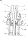
- the cylinder 6 is held at the outer circumference by a cylindrical fitting portion 7a of a cylinder holder 7.
- the cylinder 6 is secured to the pump housing 1 by screwing a screw 7g that is threaded on the outer circumference of the cylinder holder 7 into a thread 1b that is made on the pump housing 1.
- a plunger seal 13 is held at the lower end of the cylinder holder 7 by a seal holder 15 and the cylinder holder 7, the seal holder 15 being fixedly press-fitted to an inner cylindrical surface portion 7c of the cylinder holder 7.
- the plunger seal 13 is held by the inner cylindrical surface portion 7c of the cylinder holder 7 coaxially with the cylindrical fitting portion 7a.
- the piston plunger 2 and the plunger seal 13 are installed in slidable contact with each other at the lower end of the cylinder 6 in the figures.
- the cylinder holder 7 is provided with an outer cylindrical surface portion 7b on which a groove 7d adapted to receive an O-ring 61 fitted thereinto is formed.
- the O-ring 61 is such that the inner wall of a fitting hole 70 on the engine side and the groove 7d of the cylinder holder 7 isolate the cam side of the engine from the outside, thereby preventing engine oil from leaking outward.
- the cylinder 6 has a pressure contact portion 6a intersecting the reciprocating direction of the piston plunger 2.
- the pressure contact portion 6a is in pressure contact with a pressure contact surface 1a of the pump housing 1.
- the pressure contact is executed by a thrust force resulting from screw-fastening.
- the pressure chamber 11 is formed by the pressure contact mentioned above. Screw-fastening torque must be controlled so that even if being highly pressurized, the fuel in the pressurizing chamber 11 will never leak out of that via the pressure contact portion.
- the cylinder 6 is deeply inserted into the pressurizing chamber 11.
- a clearance 1B is provided between the outer circumference of the cylinder 6 and the inner circumference of the pump housing 1.
- the cylinder 6 is held at the outer circumference by the cylindrical fitting portion 7a of the cylinder holder 7. Therefore, the provision of the clearance 1B can eliminate the contact between the outer circumference of the cylinder 6 and the inner circumference of the pump housing 1.
- the cylinder 6 can hold the piston plunger 2 advancing and retreating in the pressurizing chamber 11, slidably in the advancing and retreating direction.
- the tappet 3 is provided at the lower end of the piston plunger 2.
- the tappet 3 is adapted to convert the rotation movement of a cam 5 attached to a camshaft of the engine into up-and-down movement and transmit the movement to the piston plunger 2.
- the plunger piston 2 is press fitted to the tappet 3 via a retainer 16 by means of a spring 4.
- the retainer 16 is fixedly press fitted to the piston plunger 2. In this way, the piston plunger 2 can be advanced and retreated (reciprocated) up and down along with the rotation movement of the cam 5.
- the piston plunger 2 repeats the reciprocating movement inside the cylinder 6. In this case, if the inner circumference of the cylinder 6 is deformed, the piston plunger 2 and the cylinder 6 may seize and fix with each other. If so, the piston plunger 2 cannot perform the reciprocating movement so that it cannot discharge fuel at high pressure.
- one of the causes of the fixation may be deformation of the inner circumferential portion (sliding portion) of the cylinder 6.
- the coaxiality between the outer cylindrical surface portion 7b and the cylindrical fitting portion 7a may be very low, the inner wall of the fitting hole 70 on the engine side and the outer cylindrical surface portion 7b come into contact with each other.
- the installation of the pump will cause a minute deformation of the cylinder 6.
- the outer surface portion 7b and the cylindrical fitting portion 7a are provided on the cylinder holder 7. If the outer cylindrical surface portion 7b and the cylindrical fitting portion 7a are made of different members each other, causes of degrading the coaxiality will inevitably occur at machined and joined portions. However, such a problem can be solved by forming the outer cylindrical surface portion 7c and the cylindrical fitting portion 7a in one and the same member.
- the cylinder 6 is formed to project toward the pressurizing chamber 11 from the pressure contact portion 6a thereof.
- the clearance 1B is defined between the outer circumference of the cylinder 6 and the inner circumference of the pump housing 1.
- the pressure contact surface between the cylinder 6 and the pump housing 1 extends in a direction intersecting the direction of the reciprocating movement of the piston plunger 2 and is disposed external of the clearance 1B.
- the cylinder 6 and the pump housing 1 are configured such that even if they are brought into pressure contact with each other, the deformation of the pressure contact portion is hard to be transmitted to the inner circumference of the cylinder 6. In this way, while the deformation of the inner circumference of the cylinder 6 is minimized, the sliding length between the cylinder 6 and the piston plunger 2 can be made long.
- the other causes of the fixation include the inclination of the piston plunger 2. This may probably occur if the coaxiality between the axis of the sliding portion between the cylinder 6 and the piston plunger 2 and the axis of the sliding portion between the plunger seal 13 and the piston plunger 2.
- the cylindrical fitting portion 7a and the inner cylindrical surface portion 7c are provided on the cylinder holder 7. If the cylindrical fitting portion 7a and the inner cylindrical surface portion 7c are made of different members each other, causes of degrading the coaxiality will inevitably occur at machined and joined portions. However, such a problem can be solved by forming the cylindrical fitting portion 7a and the inner cylindrical surface portion 7c in one and the same member.
- the cylindrical fitting portion 7a, the outer cylindrical surface portion 7b and the inner cylindrical surface portion 7c are all configured to be provided on the cylinder holder 7.
- This configuration can concurrently solve the problem of the coaxiality between the outer cylindrical surface portion 7b and the cylindrical fitting portion 7a and between the cylindrical fitting portion 7a and the inner cylindrical surface portion 7c. Further, as a result, the deformation of the inner circumferential portion (the sliding portion) of the cylinder 6 and the inclination of the piston plunger can concurrently be solved.
- the intake passage 10c is connected to a seal chamber 10f through an intake passage 10d and through an intake passage 10e provided in the cylinder holder 7.
- the seal chamber 10f constantly undergoes the pressure of intake fuel.
- a small amount of high-pressure fuel flows into the seal chamber 10f through the slide clearance between the cylinder 6 and the piston plunger 2.
- the plunger seal 13 will not be damaged due to high pressure.
- the piston plunger 2 is composed of a large-diameter portion 2a sliding along the cylinder 6 and a small-diameter portion 2b sliding along the plunger seal 13.
- the large-diameter portion 2a has a diameter greater than that of the small-diameter portion 2b.
- the large-diameter portion 2a and the small-diameter portion 2b are designed coaxially with each other.
- the sliding portion with the cylinder 6 is the large-diameter portion 2a and the sliding portion with the plunger seal 13 is the small-diameter portion 2b.
- the piston plunger 2 Since the piston plunger 2 repeatedly slides along the plunger seal 13 and the cylinder 6, it generates friction heat. Because of the friction heat, the large-diameter portion 2a of the piston plunger 2 is thermally expanded. A portion of the large-diameter portion 2a, which is closer to the plunger seal 13 is closer to a heat-generating source than another portion of the larger diameter portion 2a, which is closer to the pressurizing chamber 11. Therefore, the thermal expansion of the large-diameter portion 2a will not be uniform and consequently the large-diameter portion 2a lowers in cylindrical degree. Thus, the plunger 2 and the cylinder 6 will seize and fix with each other.
- the sliding movement of the piston plunger 2 constantly changes the fuel in the seal chamber 10f.
- This fuel has an effect of removing the heat generated. This effect can prevent the deformation of the large-diameter portion 2a due to the friction heat so as to prevent the seizure and fixation between the piston plunger 2 and the cylinder 6 that occur due to the deformation.
- Fig. 8 illustrates a state before the cylinder holder 7 is secured to the pump housing 1 by means of screws.
- the piston plunger 2, the cylinder 6, the seal holder 15, the plunger seal 13, the cylinder holder 7, the spring 4 and the retainer 16 constitute a plunger unit 80.
- Fig. 9 illustrates a method of assembling the plunger unit 80.
- the piston plunger 2, the cylinder 6, the seal holder 15, and the plunger seal 13 are first assembled into the cylinder holder 7 from the upper left in the figure.
- the seal holder 15 is fixedly press-fitted into the inner cylindrical surface portion 7c of the cylinder holder 7 as described above.
- the spring 4 and retainer 16 are assembled from the lower right in the figure.
- the retainer 16 is fixedly press-fitted into the piston plunger 2.
- the O-ring 61 and an O-ring 62 are attached to the plunger unit 80, they are fixedly fastened to the pump housing 1 by means of the screws as described above.
- the fastening is performed by use of a hexagonal portion 7e formed on the cylinder holder 7.
- the hexagonal portion 7e is shaped internally-hexagonally.
- a screw is fastened by torque generated by use of a specialized tool. By controlling the torque, a surface pressure between the pressure contact portion 6a and the pressure contact surface 1a is controlled.
- an O-ring 62 is attached to the outer circumferential groove 7f of the cylinder 7.
- the metal diaphragm damper 9 is composed of two metal diaphragms.
- the metal diaphragms are secured to each other in full-circumferentially by welding their welded portions in the state where gas is sealed in a space between the metal diaphragms.
- the metal diaphragm dumper 9 has a mechanism as below. When low-pressure pulsations are applied to both the surfaces of the dumper 9, the dumper 9 varies in capacity to thereby reduce the low-pressure pulsations.
- the high-pressure fuel pump is secured to the engine by means of a flange 41, setscrews 42 and bushes 43.
- the flange 41 is full-circumferentially welded and joined to the pump housing 1 at a welded portion 41a.
- the present embodiment uses laser welding.
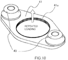
- Fig. 10 is a perspective view of the flange 41 and bushes 43. This figure illustrates only the flange 41 and the bushes 43 and omits the other parts.
- the two bushes 43 are attached to the flange 41 on a side opposite the engine.
- the two setscrews 42 are screwed to respective threads formed on the engine side.
- the high-pressure fuel pump is secured to the engine by pressing the two bushes 43 and flange 41 to the engine.
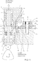
- Fig. 11 is an enlarged view illustrating a portion associated with the flange 41, setscrew 42 and bush 43.
- the bush 43 has a flange portion 43a and a caulking portion 43b.
- the caulking portion 43b is caulked and fitted into an attachment hole of the flange 41.
- the pump housing 1 and a welded portion 41a are joined together by laser welding.
- a resin fastener 44 is inserted into the bush 43 and further the setscrew 42 is inserted into the fastener 44.
- the fastener 44 plays a role of temporarily fixing the setscrew 42 to the bush 43. In other words, before the high-pressure fuel pump is mounted to the engine, the fastener 44 fixes the setscrew 42 to prevent it from falling off from the bush 43.
- the setscrew 42 is fixedly screwed to the thread portion provided on the engine side. In this case, the setscrew 42 can be turned in the bush 43 by the fastening torque of the setscrew 42.
- the pressurizing chamber 11 While the high-pressure fuel pump repeats high-pressure discharge, the pressurizing chamber 11 repeatedly undergoes high pressure and low pressure therein as described above.
- the pump housing 1 undergoes the force resulting from the high pressure so as to be lifted upward in the figures.
- the pressurizing chamber 11 has low pressure therein, the pump housing 1 does not undergo such a force. Because of this, the pump housing will undergo repeated loading upward in the figures.
- the flange 41 serves to secure the pump housing 1 to the engine by means of the two setscrews 42. Consequently, when the pump housing 1 is lifted upward as described above, the flange 42 undergoes repeated bending loads at the central portion with portions corresponding to the two setscrews 42 and to the bushes 43 secured. The repeated bending loads deform the flange 41 and the pump housing 1 to cause repeated stress therein, which leads to a problem of fatigue breakdown. Further, also the cylinder holder 7 and the cylinder 6 are deformed; therefore, also the sliding portion of the cylinder 6 is deformed so that the seizure and fixation between the piston plunger 2 and the cylinder 6 occur as described above.
- the flange 41 is manufactured by press forming for the reason of productivity.
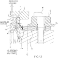
- a welded portion 41 or a joined portion between pump housing 1 and the flange 42 is joined together by laser welding.
- the laser welding needs a laser beam emitted from the downside in the figure. It is impossible to emit a laser beam from the upside to the full circumference because other component parts are present thereabove. Further, the laser welding has to penetrate the flange 41 with a thickness t of 4 mm. If the laser welding does not penetrate it, the end face of the welded portion becomes notched. The stress resulting from the repeated loads mentioned above concentrates on the notched portion, which leads to fatigue breakdown.
- the thickness t2 of the welded portion 41a is 3 mm in the present embodiment. This makes it possible to penetration-weld the flange 41a by laser welding, whereby the occurrence of spatters can be minimized.
- a portion with a thickness t2 of 3mm can be formed by press forming, which yields high productivity.
- a stepped portion between the portion with a thickness t2 of 3 mm in the welded portion 41a and the portion with a thickness t1 of 4mm is provided on the engine side.
- a void 45 is formed.
- the upper end face and lower end face of the welded portion 41a inevitably protrude from a base material.
- the provision of the void 45 can prevent the protrusion and the engine from interfering with each other. If the protrusion and the engine are in contact with each other, when the high-pressure fuel pump is secured to the engine by means of the setscrews 42, the flange 41 causes bending stress, leading to breakage.
- the provision of the void 45 can prevent the flange 41 from being damaged due to the repeated loading resulting from the high-pressure discharge. In addition, the provision of the void 45 can prevent the flange 41 from being damaged, which is due to contact between the protrusion of the welded portion 41a and the engine.
- the pump housing 1 undergoes repeated loading, it bents in the direction of the repeated loading with the portions corresponding to the two setscrews 42 and to the bushes 43 secured. Since the welded portion 41a is penetration-welded along the full circumference by laser welding, the bending of the flange 41 affects the pump housing 1.
- the cylinder holder 7 and the pump housing 1 are in contact with each other at portions corresponding to the screw 7g and to the thread 1b.
- the thread 1b of the pump housing 1 and the welded portion 41a are located at respective positions spaced a distance m apart from each other.
- the pump housing 1 has a minimum thickness of n at a position corresponding to the distance m from the welded portion 41a. The values of m and n are selected so that even if the pump housing 1 is deformed by the bending of the flange 41, the portions corresponding to the distance m and thickness n accommodate the deformation so as not to affect up to the thread 1b.
- the pump housing 1 has to accommodate all the bending of the flange 41. In the event that the repeated stress caused in the pump housing 1 exceeds an allowable value, the pump housing 1 is subjected to fatigue breakdown, leading to fuel leakage trouble.
- Fig. 12 is an enlarged view illustrating the vicinity of the welded portion 41a.
- the pump housing 1 is pulled upward in the figure by the repeated loading to bend the flange 41, causing stress. Its maximum stress occurs in the front surface of the pump housing 1 in arrow directions as depicted as "maximum stress" in Fig. 11 .
- the pump housing 1 may be shaped so that the occurring stress may be dispersed as much as possible by the shaping effect so as not to cause stress concentration.
- the present embodiment provides a structure where an R-portion 1c and an R-portion 1e are connected to each other through a straight portion 1d as shown in the figure.
- the R-portions 1c, 1e and the straight portion 1d are designed to select respective optimum values.
- the straight portion 1d lies between the two R-portions 1c and 1e and stress occurring on the straight portion 1d is distributed uniformly. As a result, stress concentration does not occur so that the maximum value of the occurring stress can be reduced.
- a bending effective distance "O" indicates a shortest distance between the ends of the two bushes 43. A portion between the ends of the two bushes 43 is substantially bent by the repeated loading. If the bending effective distance "O" can be reduced, the rigidity of the flange 41 can be enhanced as a consequence.
- the flange portion 43a is provided on the bush 43 in order to reduce the bending effective distance "O".
- the bush 43 needs such a height as to receive the fastener 44 inserted therethrough. If the height increases the external shape of the bush 43, there are problems of interference with the pump housing 1, of the increase of the material of the bush 43, etc. The provision of the flange portion 43a can prevent such problems and reduce the bending effective distance "O".
- the configurations as described above can achieve the methods (1) and (2) and make the repeated stress occurring in the pump housing 1 lower than the allowable value of fatigue breakdown.
- valve seat (52) member and the bearing member (bearing 98) of the movable plunger (valve stem 92) attached with the valve member (94) at the distal end are composed of different members each other, which are integrally assembled into one unit.
- the present embodiment can reduce the leakage of fluid from the seat portion of the electromagnetically-driven valve mechanism used in e.g. the variable capacity control mechanism of the high-pressure fuel pump.
- valve seat member and the valve member are configured in a single piece resulting from machining one and the same member.
- the gap between the movable plunger and the bearing can be made smaller than ever before. Consequently, the inclination of the movable plunger can be suppressed, sealing performance between the valve seat member and the valve member can be enhanced and thus fluid control accuracy can be improved.
- An electromagnetically-driven valve mechanism including: an externally-open type valve member disposed at a fluid inlet port; a movable plunger operated by an electromagnetic force; a holder securing the cylinder to the pump housing; a restricting member restricting the displacement of the plunger at a specific position; a spring member biasing the movable plunger on the side opposite the restricting member; an electromagnetic drive mechanism for electromagnetically biasing the movable plunger to bias the valve member and the movable plunger in the direction of closing the fluid inlet port; a valve seat with and from which the valve member comes into close contact and moves away; and a bearing member supporting the movable plunger in a reciprocatable manner; wherein the valve seat and the bearing member are made of a single piece resulting from machining one and the same member.
- Mode 2 The electrically-driven valve mechanism recited in mode 1, wherein an anchor is secured to an end of the movable plunger on the side opposite the valve member, the anchor is disposed to face the restricting member through a magnetic gap, the restricting member constitutes a magnetic core portion of the electromagnetic drive mechanism, a cap member made of a magnetic material is secured to the magnetic core portion of the restricting member to surround the anchor and the magnetic gap and seal the inside thereof, an electromagnetic coil is attached to the outer circumference of the cap member made of the magnetic material, and a yoke portion is disposed on the outer circumference of the electromagnetic coil to form a magnetic path in cooperation with the anchor, the magnetic gap, the magnetic core portion and the cap member.
- Mode 3 The electrically-driven valve mechanism recited in mode 1, wherein the electromagnetic drive mechanism has a body portion made of a magnetic material, and the bearing member is fixedly press fitted into the inner circumferential wall of the internal through-hole formed in the body portion of the electromagnetic drive mechanism.
- Mode 4 The electrically-driven valve mechanism recited in mode 1, wherein an anchor is secured to an end of the movable plunger on the side opposite the valve member, the anchor is disposed to face the restricting member through a magnetic gap, the restricting member constitutes a magnetic core portion of the electromagnetic drive mechanism, a cap member made of magnetic material is secured to a magnetic core portion of the restricting member to surround the anchor and the magnetic gap and seal the inside thereof, an electromagnetic coil is attached to the outer circumference of the cap member, a yoke member is disposed on the outer circumference of the electromagnetic coil so as to form a magnetic path in cooperation with the anchor, the magnetic gap, the magnetic core portion and the cap member, the magnetic drive mechanism has a body portion made of a magnetic material, and the bearing member is fixedly secured to the inner circumferential wall of an inner through-hole formed in the body portion of the electromagnetic drive mechanism.
- Mode 5 The electrically-driven valve mechanism recited in mode 2 or 4, wherein a coil spring as the spring member is installed between the inner circumferential portion of the anchor and the outer circumference of the movable plunger.
- Mode 6 The electrically-driven valve mechanism recited in mode 2, 4 or 5, wherein in a state where the anchor is attached, the movable plunger and the valve member formed integrally with each other have an axial gravity center disposed at a position closer to the anchor than to an axially central portion of the bearing member.
- Mode 7 The electrically-driven valve mechanism recited in mode 2 or 4, wherein the electrically-driven valve mechanism includes a resin molded body portion surrounding at least part of the outer circumference of the yoke portion, and the resin molded body portion is integrally provided with a connector and a joined portion between a terminal of the connector, and a terminal of the electromagnetic coil is formed external of the yoke portion.
- Mode 8 The electrically-driven valve mechanism recited in mode 1, wherein force other than the electromagnetic force is designed to assist the movement of the movable plunger in the same direction as the movement of the movable plunger by the electromagnetic force, and after a specific displacement of the movable plunger in a direction of the restricting member by the force other than the electromagnetic force, the electromagnetic force is applied to the movable plunger.
- Mode 9 The electrically-driven valve mechanism recited in mode 1, wherein after the valve member has initially operatively been opened against the force of the spring member due to a fluid differential pressure between the upstream side and downstream side of the valve member, the electromagnetic drive mechanism biases the movable plunger in a direction of maintaining or assisting the opening-directional operation of the valve member.
- Mode 10 A high-pressure fuel pump having an inlet valve composed of the electromagnetically-driven valve mechanism recited in any one of modes 1 to 7.
- Mode 11 The high-pressure fuel pump recited in mode 10, wherein in a state where the electromagnetic drive mechanism is not energized and the fluid differential pressure does not exist, the inlet valve member is closed by the spring member.
- Mode 12 The high-pressure fuel pump recited in mode 10, wherein the inlet valve member is operatively opened or is maintained in an opened state by applying input voltage to the electromagnetic drive mechanism in an intake process of the piston plunger constituting part of the high-pressure fuel pump.
- Mode 13 The high-pressure fuel pump recited in mode 10, 11 or 12, wherein after the inlet valve member has operatively been opened against a biasing force of the spring member due to a fluid differential pressure between an intake path side and a pressurizing chamber side of the inlet valve member, the opening operation of the inlet valve member is maintained or assisted by applying input voltage to the electromagnetic drive mechanism.
- Mode 14 The high-pressure fuel pump recited in mode 10, wherein after the opening state has been maintained with input voltage remaining applied to the electromagnetic drive mechanism, the input voltage is turned off in a compression process of the piston plunger to turn off an electric current flowing to the electromagnetic drive mechanism.
- Mode 15 The high-pressure fuel pump recited in mode 10, wherein timing to turn off the input voltage applied to the electromagnetic drive mechanism is controlled according to movement of the piston plunger to control a flow rate of fuel discharged at high pressure.
- Mode 16 The high-pressure fuel pump recited in mode 10, wherein a value of electric current occurring in the electromagnetic drive mechanism is controlled by varying input voltage.
- Mode 17 The high-pressure fuel pump recited in mode 10, wherein during a time period from application of input voltage to the electromagnetic drive mechanism to the cancel of the application, the application of the input voltage and the cancel of the application are periodically repeated in further shorter periods.
- Mode 18 The high-pressure fuel pump recited in mode 10, wherein the electromagnetic inlet valve is assembled as a unit.
- the assembly mechanism of the present invention is useful as a mechanism for assembling the high-pressure fuel pump into the engine block.
Landscapes
- Engineering & Computer Science (AREA)
- Mechanical Engineering (AREA)
- General Engineering & Computer Science (AREA)
- Chemical & Material Sciences (AREA)
- Combustion & Propulsion (AREA)
- Fuel-Injection Apparatus (AREA)
Applications Claiming Priority (2)
| Application Number | Priority Date | Filing Date | Title |
|---|---|---|---|
| JP2008279041A JP5478051B2 (ja) | 2008-10-30 | 2008-10-30 | 高圧燃料供給ポンプ |
| PCT/JP2009/068617 WO2010050569A1 (ja) | 2008-10-30 | 2009-10-29 | 高圧燃料供給ポンプ |
Publications (3)
| Publication Number | Publication Date |
|---|---|
| EP2341237A1 EP2341237A1 (en) | 2011-07-06 |
| EP2341237A4 EP2341237A4 (en) | 2017-05-17 |
| EP2341237B1 true EP2341237B1 (en) | 2018-07-18 |
Family
ID=42128928
Family Applications (1)
| Application Number | Title | Priority Date | Filing Date |
|---|---|---|---|
| EP09823679.7A Active EP2341237B1 (en) | 2008-10-30 | 2009-10-29 | Pump for supplying high-pressure fuel |
Country Status (5)
| Country | Link |
|---|---|
| US (1) | US9410519B2 (enExample) |
| EP (1) | EP2341237B1 (enExample) |
| JP (1) | JP5478051B2 (enExample) |
| CN (1) | CN102197212B (enExample) |
| WO (1) | WO2010050569A1 (enExample) |
Families Citing this family (33)
| Publication number | Priority date | Publication date | Assignee | Title |
|---|---|---|---|---|
| JP5372692B2 (ja) * | 2009-10-06 | 2013-12-18 | 日立オートモティブシステムズ株式会社 | 高圧燃料ポンプ |
| US8646436B2 (en) * | 2010-07-06 | 2014-02-11 | Toyota Boshoku Kabushiki Kaisha | Fuel pump attachment structure |
| EP2708729B1 (en) | 2011-05-13 | 2015-09-30 | Mikuni Corporation | High-pressure fuel pump device |
| EP2535554A1 (en) * | 2011-06-15 | 2012-12-19 | Delphi Technologies Holding S.à.r.l. | Electro-valve for discharging common rail |
| JP5628121B2 (ja) | 2011-09-20 | 2014-11-19 | 日立オートモティブシステムズ株式会社 | 高圧燃料供給ポンプ |
| DE102011083787A1 (de) * | 2011-09-29 | 2013-04-04 | Hengst Gmbh & Co. Kg | Kraftstoffpumpanordnung |
| CN106014736B (zh) * | 2011-11-30 | 2019-04-09 | 日立汽车系统株式会社 | 高压燃料供给泵 |
| WO2013080253A1 (ja) * | 2011-11-30 | 2013-06-06 | 日立オートモティブシステムズ株式会社 | 高圧燃料供給ポンプ |
| DE102013204549A1 (de) * | 2013-03-15 | 2014-09-18 | Robert Bosch Gmbh | Hochdruckpumpe, insbesondere Steckpumpe, für ein Kraftstoffsystem für eine Brennkraftmaschine |
| DE102013219712B4 (de) * | 2013-09-30 | 2020-04-23 | Continental Automotive Gmbh | Dämpfer mit Stützring für eine Dichtung |
| JP6387812B2 (ja) * | 2014-12-05 | 2018-09-12 | 株式会社デンソー | 高圧ポンプ、及び、それを用いる燃料供給システム |
| GB201508608D0 (en) * | 2015-05-20 | 2015-07-01 | Delphi Int Operations Lux Srl | Fuel pump apparatus |
| GB2544527A (en) * | 2015-11-20 | 2017-05-24 | Gm Global Tech Operations Llc | Fuel unit pump assembly comprising an isolator |
| DE102016206459B3 (de) * | 2016-04-18 | 2017-10-05 | Continental Automotive Gmbh | Kombination, umfassend ein Gehäuse und einen Flansch, und Anordnung |
| DE102016206456B4 (de) * | 2016-04-18 | 2017-11-09 | Continental Automotive Gmbh | Kombination, umfassend ein Gehäuse und einen Flansch, und Anordnung |
| JP6569589B2 (ja) | 2016-04-28 | 2019-09-04 | 株式会社デンソー | 高圧ポンプ |
| DE102016213451A1 (de) | 2016-05-19 | 2017-11-23 | Robert Bosch Gmbh | Kraftstoff-Hochdruckpumpe |
| US20170335834A1 (en) * | 2016-05-23 | 2017-11-23 | Caterpillar Inc. | Pump for fluid system and method of operating same |
| DE102016217409A1 (de) * | 2016-09-13 | 2018-03-15 | Robert Bosch Gmbh | Kraftstoff-Hochdruckpumpe |
| JP2018178969A (ja) * | 2017-04-21 | 2018-11-15 | 日立オートモティブシステムズ株式会社 | 高圧燃料供給ポンプ |
| DE102017207207A1 (de) * | 2017-04-28 | 2018-10-31 | Robert Bosch Gmbh | Kraftstoffpumpe |
| JP6397961B2 (ja) * | 2017-05-22 | 2018-09-26 | 日立オートモティブシステムズ株式会社 | 高圧燃料供給ポンプ |
| JP7022380B2 (ja) * | 2018-01-31 | 2022-02-18 | いすゞ自動車株式会社 | 燃料ポンプ組付構造 |
| MX2020009515A (es) * | 2018-03-14 | 2021-04-12 | Nostrum Energy Pte Ltd | Bomba para motor de combustion interna y metodo de formacion de esta. |
| JP6681448B2 (ja) * | 2018-08-31 | 2020-04-15 | 日立オートモティブシステムズ株式会社 | 高圧燃料供給ポンプ |
| WO2020175048A1 (ja) * | 2019-02-25 | 2020-09-03 | 日立オートモティブシステムズ株式会社 | 燃料ポンプ |
| DE102019204995B4 (de) * | 2019-04-08 | 2024-03-07 | Vitesco Technologies GmbH | Pumpe für ein Kraftfahrzeug und Verfahren zum Herstellen einer Pumpe |
| GB2591519B (en) * | 2020-02-03 | 2024-03-27 | Delphi Automotive Systems Lux | Inlet metering valve for an engine fuel pump |
| DE102020104313B3 (de) * | 2020-02-19 | 2021-01-28 | Schaeffler Technologies AG & Co. KG | Stößel zur Beaufschlagung eines Pumpenkolbens einer Kraftstoffhochdruckpumpe |
| US12006901B2 (en) * | 2020-07-17 | 2024-06-11 | Hitachi Astemo, Ltd. | Fuel pump |
| JP7783702B2 (ja) * | 2021-07-06 | 2025-12-10 | 三菱重工エンジン&ターボチャージャ株式会社 | 燃料ポンプ |
| US11939941B2 (en) * | 2022-03-24 | 2024-03-26 | Delphi Technologies Ip Limited | Gasoline direct injection fuel pump with isolated plunger sleeve |
| GB2626767B (en) * | 2023-02-02 | 2025-04-23 | Phinia Delphi Luxembourg Sarl | Pump-flange assembly process |
Family Cites Families (31)
| Publication number | Priority date | Publication date | Assignee | Title |
|---|---|---|---|---|
| IT1204924B (it) * | 1986-03-22 | 1989-03-10 | Bosch Gmbh Robert | Pompa di iniezione del carburante per motori endotermici |
| CH672168A5 (enExample) * | 1987-01-30 | 1989-10-31 | Nova Werke Ag | |
| DE69501863T2 (de) | 1994-09-09 | 1998-07-23 | Gen Motors Corp | Stellantrieb für ein Abgasrückführungsventil |
| JP3180948B2 (ja) * | 1996-09-03 | 2001-07-03 | 株式会社ボッシュオートモーティブシステム | ダイヤフラム型ダンパ |
| JP3309765B2 (ja) * | 1997-05-16 | 2002-07-29 | 三菱電機株式会社 | 高圧燃料供給ポンプ |
| JP2857139B1 (ja) * | 1998-01-30 | 1999-02-10 | 三菱電機株式会社 | 高圧燃料供給ポンプ |
| FI108071B (fi) * | 1998-07-03 | 2001-11-15 | Waertsilae Tech Oy Ab | Integroitu pumppu- ja nostinyksikkö polttoaineensyöttöjärjestelmässä |
| GB9917998D0 (en) * | 1999-07-30 | 1999-09-29 | Lucas Ind Plc | Fuel pump |
| JP2001059466A (ja) * | 1999-08-20 | 2001-03-06 | Mitsubishi Electric Corp | 高圧燃料ポンプ |
| JP3767268B2 (ja) * | 1999-09-10 | 2006-04-19 | 三菱電機株式会社 | 高圧燃料供給装置 |
| JP2001221129A (ja) * | 2000-02-10 | 2001-08-17 | Hitachi Ltd | 高圧燃料ポンプ |
| EP1312793B1 (en) * | 2000-08-24 | 2010-12-22 | Mitsubishi Denki Kabushiki Kaisha | High-pressure fuel feed device |
| EP1801411B1 (en) * | 2001-01-05 | 2009-08-05 | Hitachi, Ltd. | Fluid pump and high-pressure fuel feed pump |
| JP3787508B2 (ja) * | 2001-07-19 | 2006-06-21 | 株式会社日立製作所 | 高圧燃料供給ポンプ |
| JP3823060B2 (ja) * | 2002-03-04 | 2006-09-20 | 株式会社日立製作所 | 高圧燃料供給ポンプ |
| JP3693992B2 (ja) * | 2002-11-08 | 2005-09-14 | 三菱電機株式会社 | 高圧燃料ポンプ |
| JP2004211574A (ja) * | 2002-12-27 | 2004-07-29 | Hitachi Ltd | 燃料ポンプ |
| DE10322599B4 (de) * | 2003-05-20 | 2013-08-08 | Robert Bosch Gmbh | Kolbenpumpe, insbesondere Hochdruck-Kraftstoffpumpe |
| DE10322604A1 (de) * | 2003-05-20 | 2004-12-09 | Robert Bosch Gmbh | Satz von Kolbenpumpen, insbesondere Kraftstoffpumpen für Brennkraftmaschinen mit Kraftstoff-Direkteinspritzung |
| JP4036153B2 (ja) * | 2003-07-22 | 2008-01-23 | 株式会社日立製作所 | ダンパ機構及び高圧燃料供給ポンプ |
| DE10344459B4 (de) | 2003-09-25 | 2012-06-14 | Robert Bosch Gmbh | Kolbenpumpe, insbesondere Hochdruck-Kolbenpumpe |
| JP4415884B2 (ja) * | 2005-03-11 | 2010-02-17 | 株式会社日立製作所 | 電磁駆動機構,電磁弁機構及び電磁駆動機構によって操作される吸入弁を備えた高圧燃料供給ポンプ,電磁弁機構を備えた高圧燃料供給ポンプ |
| DE102005033634A1 (de) * | 2005-07-19 | 2007-01-25 | Robert Bosch Gmbh | Hochdruck-Kraftstoffpumpe für ein Kraftstoff-Einspritzsystem einer Brennkraftmaschine |
| JP4415929B2 (ja) * | 2005-11-16 | 2010-02-17 | 株式会社日立製作所 | 高圧燃料供給ポンプ |
| JP4648254B2 (ja) * | 2006-06-22 | 2011-03-09 | 日立オートモティブシステムズ株式会社 | 高圧燃料ポンプ |
| JP4625789B2 (ja) * | 2006-07-20 | 2011-02-02 | 日立オートモティブシステムズ株式会社 | 高圧燃料ポンプ |
| JP2008057451A (ja) * | 2006-08-31 | 2008-03-13 | Hitachi Ltd | 高圧燃料供給ポンプ |
| WO2008086011A2 (en) * | 2007-01-10 | 2008-07-17 | Stanadyne Corporation | Load ring mounting of pumping plunger |
| JP4686501B2 (ja) * | 2007-05-21 | 2011-05-25 | 日立オートモティブシステムズ株式会社 | 液体脈動ダンパ機構、および液体脈動ダンパ機構を備えた高圧燃料供給ポンプ |
| JP5039507B2 (ja) * | 2007-10-31 | 2012-10-03 | 日立オートモティブシステムズ株式会社 | 高圧燃料供給ポンプおよびその製造方法 |
| JP5002523B2 (ja) * | 2008-04-25 | 2012-08-15 | 日立オートモティブシステムズ株式会社 | 燃料の圧力脈動低減機構、及びそれを備えた内燃機関の高圧燃料供給ポンプ |
-
2008
- 2008-10-30 JP JP2008279041A patent/JP5478051B2/ja active Active
-
2009
- 2009-10-29 EP EP09823679.7A patent/EP2341237B1/en active Active
- 2009-10-29 CN CN200980142941.6A patent/CN102197212B/zh active Active
- 2009-10-29 US US13/125,106 patent/US9410519B2/en active Active
- 2009-10-29 WO PCT/JP2009/068617 patent/WO2010050569A1/ja not_active Ceased
Also Published As
| Publication number | Publication date |
|---|---|
| EP2341237A4 (en) | 2017-05-17 |
| JP2010106740A (ja) | 2010-05-13 |
| US9410519B2 (en) | 2016-08-09 |
| JP5478051B2 (ja) | 2014-04-23 |
| EP2341237A1 (en) | 2011-07-06 |
| WO2010050569A1 (ja) | 2010-05-06 |
| US20110253109A1 (en) | 2011-10-20 |
| CN102197212B (zh) | 2014-07-30 |
| CN102197212A (zh) | 2011-09-21 |
Similar Documents
| Publication | Publication Date | Title |
|---|---|---|
| EP2341237B1 (en) | Pump for supplying high-pressure fuel | |
| EP2182199B1 (en) | Electromagnetically-driven valve mechanism and high-pressure fuel supply pump using the same | |
| JP2010106740A5 (enExample) | ||
| JP6648237B2 (ja) | 高圧燃料供給ポンプ | |
| JP6779370B2 (ja) | 高圧燃料ポンプ | |
| US20200011314A1 (en) | High pressure fuel pump | |
| JP5905046B2 (ja) | 電磁吸入弁を備えた高圧燃料供給ポンプ | |
| JP6681448B2 (ja) | 高圧燃料供給ポンプ | |
| JP2015218678A (ja) | リリーフ弁を備えた高圧燃料供給ポンプ | |
| JP5081869B2 (ja) | 高圧燃料供給ポンプ | |
| CN106014736A (zh) | 高压燃料供给泵 | |
| JP2018119479A (ja) | 高圧燃料ポンプ | |
| JP6151399B2 (ja) | 高圧燃料供給ポンプ | |
| JP6397961B2 (ja) | 高圧燃料供給ポンプ | |
| JPWO2019012969A1 (ja) | 電磁吸入弁、及びこれを備えた高圧燃料ポンプ | |
| JP7024071B2 (ja) | 燃料供給ポンプ | |
| WO2019225069A1 (ja) | 燃料ポンプ | |
| JP2018031332A (ja) | 高圧燃料供給ポンプ |
Legal Events
| Date | Code | Title | Description |
|---|---|---|---|
| PUAI | Public reference made under article 153(3) epc to a published international application that has entered the european phase |
Free format text: ORIGINAL CODE: 0009012 |
|
| 17P | Request for examination filed |
Effective date: 20110530 |
|
| AK | Designated contracting states |
Kind code of ref document: A1 Designated state(s): AT BE BG CH CY CZ DE DK EE ES FI FR GB GR HR HU IE IS IT LI LT LU LV MC MK MT NL NO PL PT RO SE SI SK SM TR |
|
| AX | Request for extension of the european patent |
Extension state: AL BA RS |
|
| DAX | Request for extension of the european patent (deleted) | ||
| RA4 | Supplementary search report drawn up and despatched (corrected) |
Effective date: 20170413 |
|
| RIC1 | Information provided on ipc code assigned before grant |
Ipc: F04B 53/16 20060101ALI20170408BHEP Ipc: F02M 59/28 20060101AFI20170408BHEP Ipc: F04B 1/04 20060101ALI20170408BHEP Ipc: F02M 59/44 20060101ALI20170408BHEP |
|
| GRAP | Despatch of communication of intention to grant a patent |
Free format text: ORIGINAL CODE: EPIDOSNIGR1 |
|
| STAA | Information on the status of an ep patent application or granted ep patent |
Free format text: STATUS: GRANT OF PATENT IS INTENDED |
|
| RIC1 | Information provided on ipc code assigned before grant |
Ipc: F02M 59/28 20060101AFI20180208BHEP Ipc: F02M 59/44 20060101ALI20180208BHEP Ipc: F04B 1/04 20060101ALI20180208BHEP Ipc: F04B 53/16 20060101ALI20180208BHEP |
|
| INTG | Intention to grant announced |
Effective date: 20180307 |
|
| GRAS | Grant fee paid |
Free format text: ORIGINAL CODE: EPIDOSNIGR3 |
|
| GRAA | (expected) grant |
Free format text: ORIGINAL CODE: 0009210 |
|
| STAA | Information on the status of an ep patent application or granted ep patent |
Free format text: STATUS: THE PATENT HAS BEEN GRANTED |
|
| RIN1 | Information on inventor provided before grant (corrected) |
Inventor name: MIYAZAKI KATSUMI Inventor name: USUI SATOSHI Inventor name: YAMADA HIROYUKI Inventor name: TAMURA SHINGO |
|
| AK | Designated contracting states |
Kind code of ref document: B1 Designated state(s): AT BE BG CH CY CZ DE DK EE ES FI FR GB GR HR HU IE IS IT LI LT LU LV MC MK MT NL NO PL PT RO SE SI SK SM TR |
|
| REG | Reference to a national code |
Ref country code: GB Ref legal event code: FG4D |
|
| REG | Reference to a national code |
Ref country code: CH Ref legal event code: EP |
|
| REG | Reference to a national code |
Ref country code: IE Ref legal event code: FG4D |
|
| REG | Reference to a national code |
Ref country code: AT Ref legal event code: REF Ref document number: 1019640 Country of ref document: AT Kind code of ref document: T Effective date: 20180815 |
|
| REG | Reference to a national code |
Ref country code: DE Ref legal event code: R096 Ref document number: 602009053373 Country of ref document: DE |
|
| REG | Reference to a national code |
Ref country code: NL Ref legal event code: MP Effective date: 20180718 |
|
| REG | Reference to a national code |
Ref country code: LT Ref legal event code: MG4D |
|
| REG | Reference to a national code |
Ref country code: AT Ref legal event code: MK05 Ref document number: 1019640 Country of ref document: AT Kind code of ref document: T Effective date: 20180718 |
|
| PG25 | Lapsed in a contracting state [announced via postgrant information from national office to epo] |
Ref country code: NL Free format text: LAPSE BECAUSE OF FAILURE TO SUBMIT A TRANSLATION OF THE DESCRIPTION OR TO PAY THE FEE WITHIN THE PRESCRIBED TIME-LIMIT Effective date: 20180718 |
|
| PG25 | Lapsed in a contracting state [announced via postgrant information from national office to epo] |
Ref country code: LT Free format text: LAPSE BECAUSE OF FAILURE TO SUBMIT A TRANSLATION OF THE DESCRIPTION OR TO PAY THE FEE WITHIN THE PRESCRIBED TIME-LIMIT Effective date: 20180718 Ref country code: IS Free format text: LAPSE BECAUSE OF FAILURE TO SUBMIT A TRANSLATION OF THE DESCRIPTION OR TO PAY THE FEE WITHIN THE PRESCRIBED TIME-LIMIT Effective date: 20181118 Ref country code: PL Free format text: LAPSE BECAUSE OF FAILURE TO SUBMIT A TRANSLATION OF THE DESCRIPTION OR TO PAY THE FEE WITHIN THE PRESCRIBED TIME-LIMIT Effective date: 20180718 Ref country code: FI Free format text: LAPSE BECAUSE OF FAILURE TO SUBMIT A TRANSLATION OF THE DESCRIPTION OR TO PAY THE FEE WITHIN THE PRESCRIBED TIME-LIMIT Effective date: 20180718 Ref country code: SE Free format text: LAPSE BECAUSE OF FAILURE TO SUBMIT A TRANSLATION OF THE DESCRIPTION OR TO PAY THE FEE WITHIN THE PRESCRIBED TIME-LIMIT Effective date: 20180718 Ref country code: NO Free format text: LAPSE BECAUSE OF FAILURE TO SUBMIT A TRANSLATION OF THE DESCRIPTION OR TO PAY THE FEE WITHIN THE PRESCRIBED TIME-LIMIT Effective date: 20181018 Ref country code: GR Free format text: LAPSE BECAUSE OF FAILURE TO SUBMIT A TRANSLATION OF THE DESCRIPTION OR TO PAY THE FEE WITHIN THE PRESCRIBED TIME-LIMIT Effective date: 20181019 Ref country code: BG Free format text: LAPSE BECAUSE OF FAILURE TO SUBMIT A TRANSLATION OF THE DESCRIPTION OR TO PAY THE FEE WITHIN THE PRESCRIBED TIME-LIMIT Effective date: 20181018 Ref country code: AT Free format text: LAPSE BECAUSE OF FAILURE TO SUBMIT A TRANSLATION OF THE DESCRIPTION OR TO PAY THE FEE WITHIN THE PRESCRIBED TIME-LIMIT Effective date: 20180718 |
|
| PG25 | Lapsed in a contracting state [announced via postgrant information from national office to epo] |
Ref country code: HR Free format text: LAPSE BECAUSE OF FAILURE TO SUBMIT A TRANSLATION OF THE DESCRIPTION OR TO PAY THE FEE WITHIN THE PRESCRIBED TIME-LIMIT Effective date: 20180718 Ref country code: LV Free format text: LAPSE BECAUSE OF FAILURE TO SUBMIT A TRANSLATION OF THE DESCRIPTION OR TO PAY THE FEE WITHIN THE PRESCRIBED TIME-LIMIT Effective date: 20180718 Ref country code: ES Free format text: LAPSE BECAUSE OF FAILURE TO SUBMIT A TRANSLATION OF THE DESCRIPTION OR TO PAY THE FEE WITHIN THE PRESCRIBED TIME-LIMIT Effective date: 20180718 |
|
| REG | Reference to a national code |
Ref country code: DE Ref legal event code: R097 Ref document number: 602009053373 Country of ref document: DE |
|
| PG25 | Lapsed in a contracting state [announced via postgrant information from national office to epo] |
Ref country code: CZ Free format text: LAPSE BECAUSE OF FAILURE TO SUBMIT A TRANSLATION OF THE DESCRIPTION OR TO PAY THE FEE WITHIN THE PRESCRIBED TIME-LIMIT Effective date: 20180718 Ref country code: IT Free format text: LAPSE BECAUSE OF FAILURE TO SUBMIT A TRANSLATION OF THE DESCRIPTION OR TO PAY THE FEE WITHIN THE PRESCRIBED TIME-LIMIT Effective date: 20180718 Ref country code: RO Free format text: LAPSE BECAUSE OF FAILURE TO SUBMIT A TRANSLATION OF THE DESCRIPTION OR TO PAY THE FEE WITHIN THE PRESCRIBED TIME-LIMIT Effective date: 20180718 Ref country code: EE Free format text: LAPSE BECAUSE OF FAILURE TO SUBMIT A TRANSLATION OF THE DESCRIPTION OR TO PAY THE FEE WITHIN THE PRESCRIBED TIME-LIMIT Effective date: 20180718 |
|
| PLBE | No opposition filed within time limit |
Free format text: ORIGINAL CODE: 0009261 |
|
| STAA | Information on the status of an ep patent application or granted ep patent |
Free format text: STATUS: NO OPPOSITION FILED WITHIN TIME LIMIT |
|
| PG25 | Lapsed in a contracting state [announced via postgrant information from national office to epo] |
Ref country code: SK Free format text: LAPSE BECAUSE OF FAILURE TO SUBMIT A TRANSLATION OF THE DESCRIPTION OR TO PAY THE FEE WITHIN THE PRESCRIBED TIME-LIMIT Effective date: 20180718 Ref country code: SM Free format text: LAPSE BECAUSE OF FAILURE TO SUBMIT A TRANSLATION OF THE DESCRIPTION OR TO PAY THE FEE WITHIN THE PRESCRIBED TIME-LIMIT Effective date: 20180718 Ref country code: DK Free format text: LAPSE BECAUSE OF FAILURE TO SUBMIT A TRANSLATION OF THE DESCRIPTION OR TO PAY THE FEE WITHIN THE PRESCRIBED TIME-LIMIT Effective date: 20180718 |
|
| REG | Reference to a national code |
Ref country code: CH Ref legal event code: PL |
|
| 26N | No opposition filed |
Effective date: 20190423 |
|
| GBPC | Gb: european patent ceased through non-payment of renewal fee |
Effective date: 20181029 |
|
| REG | Reference to a national code |
Ref country code: BE Ref legal event code: MM Effective date: 20181031 |
|
| PG25 | Lapsed in a contracting state [announced via postgrant information from national office to epo] |
Ref country code: MC Free format text: LAPSE BECAUSE OF FAILURE TO SUBMIT A TRANSLATION OF THE DESCRIPTION OR TO PAY THE FEE WITHIN THE PRESCRIBED TIME-LIMIT Effective date: 20180718 Ref country code: LU Free format text: LAPSE BECAUSE OF NON-PAYMENT OF DUE FEES Effective date: 20181029 |
|
| REG | Reference to a national code |
Ref country code: IE Ref legal event code: MM4A |
|
| PG25 | Lapsed in a contracting state [announced via postgrant information from national office to epo] |
Ref country code: CH Free format text: LAPSE BECAUSE OF NON-PAYMENT OF DUE FEES Effective date: 20181031 Ref country code: BE Free format text: LAPSE BECAUSE OF NON-PAYMENT OF DUE FEES Effective date: 20181031 Ref country code: LI Free format text: LAPSE BECAUSE OF NON-PAYMENT OF DUE FEES Effective date: 20181031 Ref country code: FR Free format text: LAPSE BECAUSE OF NON-PAYMENT OF DUE FEES Effective date: 20181031 Ref country code: SI Free format text: LAPSE BECAUSE OF FAILURE TO SUBMIT A TRANSLATION OF THE DESCRIPTION OR TO PAY THE FEE WITHIN THE PRESCRIBED TIME-LIMIT Effective date: 20180718 |
|
| PG25 | Lapsed in a contracting state [announced via postgrant information from national office to epo] |
Ref country code: IE Free format text: LAPSE BECAUSE OF NON-PAYMENT OF DUE FEES Effective date: 20181029 Ref country code: GB Free format text: LAPSE BECAUSE OF NON-PAYMENT OF DUE FEES Effective date: 20181029 |
|
| PG25 | Lapsed in a contracting state [announced via postgrant information from national office to epo] |
Ref country code: MT Free format text: LAPSE BECAUSE OF NON-PAYMENT OF DUE FEES Effective date: 20181029 |
|
| PG25 | Lapsed in a contracting state [announced via postgrant information from national office to epo] |
Ref country code: TR Free format text: LAPSE BECAUSE OF FAILURE TO SUBMIT A TRANSLATION OF THE DESCRIPTION OR TO PAY THE FEE WITHIN THE PRESCRIBED TIME-LIMIT Effective date: 20180718 |
|
| PG25 | Lapsed in a contracting state [announced via postgrant information from national office to epo] |
Ref country code: PT Free format text: LAPSE BECAUSE OF FAILURE TO SUBMIT A TRANSLATION OF THE DESCRIPTION OR TO PAY THE FEE WITHIN THE PRESCRIBED TIME-LIMIT Effective date: 20180718 |
|
| PG25 | Lapsed in a contracting state [announced via postgrant information from national office to epo] |
Ref country code: HU Free format text: LAPSE BECAUSE OF FAILURE TO SUBMIT A TRANSLATION OF THE DESCRIPTION OR TO PAY THE FEE WITHIN THE PRESCRIBED TIME-LIMIT; INVALID AB INITIO Effective date: 20091029 Ref country code: CY Free format text: LAPSE BECAUSE OF FAILURE TO SUBMIT A TRANSLATION OF THE DESCRIPTION OR TO PAY THE FEE WITHIN THE PRESCRIBED TIME-LIMIT Effective date: 20180718 Ref country code: MK Free format text: LAPSE BECAUSE OF NON-PAYMENT OF DUE FEES Effective date: 20180718 |
|
| REG | Reference to a national code |
Ref country code: DE Ref legal event code: R082 Ref document number: 602009053373 Country of ref document: DE Representative=s name: MERH-IP MATIAS ERNY REICHL HOFFMANN PATENTANWA, DE Ref country code: DE Ref legal event code: R081 Ref document number: 602009053373 Country of ref document: DE Owner name: HITACHI ASTEMO, LTD., HITACHINAKA-SHI, JP Free format text: FORMER OWNER: HITACHI AUTOMOTIVE SYSTEMS, LTD., HITACHINAKA-SHI, IBARAKI, JP |
|
| PGFP | Annual fee paid to national office [announced via postgrant information from national office to epo] |
Ref country code: DE Payment date: 20250902 Year of fee payment: 17 |