WO2010047095A1 - 動力伝達装置 - Google Patents
動力伝達装置 Download PDFInfo
- Publication number
- WO2010047095A1 WO2010047095A1 PCT/JP2009/005504 JP2009005504W WO2010047095A1 WO 2010047095 A1 WO2010047095 A1 WO 2010047095A1 JP 2009005504 W JP2009005504 W JP 2009005504W WO 2010047095 A1 WO2010047095 A1 WO 2010047095A1
- Authority
- WO
- WIPO (PCT)
- Prior art keywords
- clutch means
- clutch
- torque converter
- drive
- power transmission
- Prior art date
- Legal status (The legal status is an assumption and is not a legal conclusion. Google has not performed a legal analysis and makes no representation as to the accuracy of the status listed.)
- Ceased
Links
Images






Classifications
-
- F—MECHANICAL ENGINEERING; LIGHTING; HEATING; WEAPONS; BLASTING
- F16—ENGINEERING ELEMENTS AND UNITS; GENERAL MEASURES FOR PRODUCING AND MAINTAINING EFFECTIVE FUNCTIONING OF MACHINES OR INSTALLATIONS; THERMAL INSULATION IN GENERAL
- F16D—COUPLINGS FOR TRANSMITTING ROTATION; CLUTCHES; BRAKES
- F16D48/00—External control of clutches
- F16D48/06—Control by electric or electronic means, e.g. of fluid pressure
- F16D48/08—Regulating clutch take-up on starting
-
- F—MECHANICAL ENGINEERING; LIGHTING; HEATING; WEAPONS; BLASTING
- F16—ENGINEERING ELEMENTS AND UNITS; GENERAL MEASURES FOR PRODUCING AND MAINTAINING EFFECTIVE FUNCTIONING OF MACHINES OR INSTALLATIONS; THERMAL INSULATION IN GENERAL
- F16D—COUPLINGS FOR TRANSMITTING ROTATION; CLUTCHES; BRAKES
- F16D21/00—Systems comprising a plurality of actuated clutches
- F16D21/02—Systems comprising a plurality of actuated clutches for interconnecting three or more shafts or other transmission members in different ways
- F16D21/06—Systems comprising a plurality of actuated clutches for interconnecting three or more shafts or other transmission members in different ways at least two driving shafts or two driven shafts being concentric
-
- F—MECHANICAL ENGINEERING; LIGHTING; HEATING; WEAPONS; BLASTING
- F16—ENGINEERING ELEMENTS AND UNITS; GENERAL MEASURES FOR PRODUCING AND MAINTAINING EFFECTIVE FUNCTIONING OF MACHINES OR INSTALLATIONS; THERMAL INSULATION IN GENERAL
- F16D—COUPLINGS FOR TRANSMITTING ROTATION; CLUTCHES; BRAKES
- F16D25/00—Fluid-actuated clutches
- F16D25/10—Clutch systems with a plurality of fluid-actuated clutches
-
- F—MECHANICAL ENGINEERING; LIGHTING; HEATING; WEAPONS; BLASTING
- F16—ENGINEERING ELEMENTS AND UNITS; GENERAL MEASURES FOR PRODUCING AND MAINTAINING EFFECTIVE FUNCTIONING OF MACHINES OR INSTALLATIONS; THERMAL INSULATION IN GENERAL
- F16H—GEARING
- F16H61/00—Control functions within control units of change-speed- or reversing-gearings for conveying rotary motion ; Control of exclusively fluid gearing, friction gearing, gearings with endless flexible members or other particular types of gearing
- F16H61/14—Control of torque converter lock-up clutches
- F16H61/143—Control of torque converter lock-up clutches using electric control means
-
- F—MECHANICAL ENGINEERING; LIGHTING; HEATING; WEAPONS; BLASTING
- F16—ENGINEERING ELEMENTS AND UNITS; GENERAL MEASURES FOR PRODUCING AND MAINTAINING EFFECTIVE FUNCTIONING OF MACHINES OR INSTALLATIONS; THERMAL INSULATION IN GENERAL
- F16D—COUPLINGS FOR TRANSMITTING ROTATION; CLUTCHES; BRAKES
- F16D21/00—Systems comprising a plurality of actuated clutches
- F16D21/02—Systems comprising a plurality of actuated clutches for interconnecting three or more shafts or other transmission members in different ways
- F16D21/06—Systems comprising a plurality of actuated clutches for interconnecting three or more shafts or other transmission members in different ways at least two driving shafts or two driven shafts being concentric
- F16D2021/063—Electric arrangements for clutch control
-
- F—MECHANICAL ENGINEERING; LIGHTING; HEATING; WEAPONS; BLASTING
- F16—ENGINEERING ELEMENTS AND UNITS; GENERAL MEASURES FOR PRODUCING AND MAINTAINING EFFECTIVE FUNCTIONING OF MACHINES OR INSTALLATIONS; THERMAL INSULATION IN GENERAL
- F16D—COUPLINGS FOR TRANSMITTING ROTATION; CLUTCHES; BRAKES
- F16D21/00—Systems comprising a plurality of actuated clutches
- F16D21/02—Systems comprising a plurality of actuated clutches for interconnecting three or more shafts or other transmission members in different ways
- F16D21/06—Systems comprising a plurality of actuated clutches for interconnecting three or more shafts or other transmission members in different ways at least two driving shafts or two driven shafts being concentric
- F16D2021/0661—Hydraulically actuated multiple lamellae clutches
-
- F—MECHANICAL ENGINEERING; LIGHTING; HEATING; WEAPONS; BLASTING
- F16—ENGINEERING ELEMENTS AND UNITS; GENERAL MEASURES FOR PRODUCING AND MAINTAINING EFFECTIVE FUNCTIONING OF MACHINES OR INSTALLATIONS; THERMAL INSULATION IN GENERAL
- F16D—COUPLINGS FOR TRANSMITTING ROTATION; CLUTCHES; BRAKES
- F16D2500/00—External control of clutches by electric or electronic means
- F16D2500/10—System to be controlled
- F16D2500/108—Gear
- F16D2500/1086—Concentric shafts
-
- F—MECHANICAL ENGINEERING; LIGHTING; HEATING; WEAPONS; BLASTING
- F16—ENGINEERING ELEMENTS AND UNITS; GENERAL MEASURES FOR PRODUCING AND MAINTAINING EFFECTIVE FUNCTIONING OF MACHINES OR INSTALLATIONS; THERMAL INSULATION IN GENERAL
- F16D—COUPLINGS FOR TRANSMITTING ROTATION; CLUTCHES; BRAKES
- F16D2500/00—External control of clutches by electric or electronic means
- F16D2500/30—Signal inputs
- F16D2500/304—Signal inputs from the clutch
- F16D2500/30402—Clutch friction coefficient
-
- F—MECHANICAL ENGINEERING; LIGHTING; HEATING; WEAPONS; BLASTING
- F16—ENGINEERING ELEMENTS AND UNITS; GENERAL MEASURES FOR PRODUCING AND MAINTAINING EFFECTIVE FUNCTIONING OF MACHINES OR INSTALLATIONS; THERMAL INSULATION IN GENERAL
- F16D—COUPLINGS FOR TRANSMITTING ROTATION; CLUTCHES; BRAKES
- F16D2500/00—External control of clutches by electric or electronic means
- F16D2500/30—Signal inputs
- F16D2500/304—Signal inputs from the clutch
- F16D2500/30406—Clutch slip
-
- F—MECHANICAL ENGINEERING; LIGHTING; HEATING; WEAPONS; BLASTING
- F16—ENGINEERING ELEMENTS AND UNITS; GENERAL MEASURES FOR PRODUCING AND MAINTAINING EFFECTIVE FUNCTIONING OF MACHINES OR INSTALLATIONS; THERMAL INSULATION IN GENERAL
- F16D—COUPLINGS FOR TRANSMITTING ROTATION; CLUTCHES; BRAKES
- F16D2500/00—External control of clutches by electric or electronic means
- F16D2500/50—Problem to be solved by the control system
- F16D2500/502—Relating the clutch
- F16D2500/50224—Drive-off
-
- F—MECHANICAL ENGINEERING; LIGHTING; HEATING; WEAPONS; BLASTING
- F16—ENGINEERING ELEMENTS AND UNITS; GENERAL MEASURES FOR PRODUCING AND MAINTAINING EFFECTIVE FUNCTIONING OF MACHINES OR INSTALLATIONS; THERMAL INSULATION IN GENERAL
- F16D—COUPLINGS FOR TRANSMITTING ROTATION; CLUTCHES; BRAKES
- F16D2500/00—External control of clutches by electric or electronic means
- F16D2500/70—Details about the implementation of the control system
- F16D2500/704—Output parameters from the control unit; Target parameters to be controlled
- F16D2500/70402—Actuator parameters
- F16D2500/70406—Pressure
-
- F—MECHANICAL ENGINEERING; LIGHTING; HEATING; WEAPONS; BLASTING
- F16—ENGINEERING ELEMENTS AND UNITS; GENERAL MEASURES FOR PRODUCING AND MAINTAINING EFFECTIVE FUNCTIONING OF MACHINES OR INSTALLATIONS; THERMAL INSULATION IN GENERAL
- F16H—GEARING
- F16H59/00—Control inputs to control units of change-speed- or reversing-gearings for conveying rotary motion
- F16H59/36—Inputs being a function of speed
- F16H59/46—Inputs being a function of speed dependent on a comparison between speeds
- F16H2059/465—Detecting slip, e.g. clutch slip ratio
- F16H2059/467—Detecting slip, e.g. clutch slip ratio of torque converter
-
- F—MECHANICAL ENGINEERING; LIGHTING; HEATING; WEAPONS; BLASTING
- F16—ENGINEERING ELEMENTS AND UNITS; GENERAL MEASURES FOR PRODUCING AND MAINTAINING EFFECTIVE FUNCTIONING OF MACHINES OR INSTALLATIONS; THERMAL INSULATION IN GENERAL
- F16H—GEARING
- F16H61/00—Control functions within control units of change-speed- or reversing-gearings for conveying rotary motion ; Control of exclusively fluid gearing, friction gearing, gearings with endless flexible members or other particular types of gearing
- F16H61/14—Control of torque converter lock-up clutches
- F16H61/143—Control of torque converter lock-up clutches using electric control means
- F16H2061/145—Control of torque converter lock-up clutches using electric control means for controlling slip, e.g. approaching target slip value
Definitions
- the present invention relates to a power transmission device which is disposed in the middle of a power transmission system from a drive source of a vehicle to a wheel, and which can optionally transmit or cut off the driving force of the drive source to the wheel.
- Conventional power transmission devices for vehicles include a torque converter (a start system called a torque converter type) and a start clutch (a so-called start clutch type). (Starting system)) has been proposed.
- a torque converter a start system called a torque converter type
- a start clutch a so-called start clutch type
- (Starting system)) has been proposed.
- the start performance can be improved by the torque amplification function of the torque converter at the time of start.
- a start clutch type automatic transmission of the start system for example, during steady traveling, there is no slip such as a torque converter, so that power transmission efficiency can be improved.
- Patent Document 1 there has been proposed an automatic transmission of a torque converter type starting system to which a lockup clutch is added.
- a lockup clutch usually has a clutch piston connected to a turbine in a torque converter, and moves between a connected position where the clutch piston abuts on the inner circumferential wall of the torque converter cover and a separated nonconnected position. In the coupled position, the torque converter cover and the turbine are configured to be directly coupled via the clutch piston.
- the automatic transmission of the torque type start system has a technical advantage that the start performance can be improved by the torque amplification function of the torque converter at the time of start, but, for example, the slip of the torque converter during steady traveling Has a technical disadvantage that the power transmission efficiency is reduced.
- a starting clutch type automatic transmission has a technical merit that power transmission efficiency can be improved because there is no slip like a torque converter during steady traveling, for example.
- the starting performance is degraded because the torque amplification function is not provided.
- a relatively complicated lockup clutch such as a lockup clutch which can be moved between a coupled position and a noncoupled position and A large structure has to be formed in the fluid atmosphere in the torque converter, which increases the manufacturing cost and the maintenance cost.
- the present invention has been made in view of such circumstances, and suppresses the complication and enlargement of the device, and aims to improve the starting performance by the torque amplification function of the torque converter, and also provide power transmission during steady traveling.
- An object of the present invention is to provide a power transmission device capable of improving the efficiency.
- a power transmission device which is disposed in the middle of a power transmission system extending from a drive source of a vehicle to a wheel and which can optionally transmit or cut off the driving force of the drive source to the wheel.
- a torque converter having a torque amplification function, first clutch means operable while the vehicle is moving forward, and transmitting the driving force of the drive source to the wheel via a drive transmission system of the torque converter; Clutch means having second clutch means for transmitting the driving force of the drive source to the wheels without via the drive transmission system of the torque converter, and the first clutch means or the first clutch means according to the state of the vehicle at the time of forward
- the second clutch means is optionally operated to transmit the driving force of the drive source to the wheel via the drive transmission system of the torque converter, or Selection means capable of transmitting the driving force of the drive source to the wheels without passing through the drive transmission system of the Cconverter, and the input side capable of measuring the rotational speed of the input side of the first clutch means in the middle of the power transmission system Measuring means, output side measuring means capable of measuring the rotational speed of the output side of the first clutch means in the middle of the power transmission system, rotational speed measured by the input side measuring means, and the output side measurement
- the drive source measurement means capable of measuring the rotational speed of the drive source of the vehicle, and the rotational speed measured by the drive source measurement means
- a torque converter slip ratio calculating unit configured to calculate a slip ratio of the torque converter from a difference or a ratio between the rotational speed measured by the input-side measuring unit and the rotational speed measured by the input-side measuring unit.
- the invention according to claim 3 is the power transmission apparatus according to claim 1 or 2, further comprising a hydraulic piston corresponding to the first clutch means, and controlling the hydraulic pressure for operating the hydraulic piston.
- the first clutch means is operable while controlling the displacement of the first clutch means, and the displacement control of the first clutch means is a slip calculated by the first clutch means slip ratio calculating means or the torque converter slip ratio calculating means. It is characterized by being performed based on a rate.
- the first clutch means and the second clutch means do not operate and the neutral state is established when the vehicle is in the stop state by the operation of the brake.
- the first clutch means is operated while carrying out a capacity control to transmit the driving force associated with the creep phenomenon of the torque converter to the wheel side.
- the invention according to claim 5 is the power transmission apparatus according to claim 4, wherein, when the vehicle is in the stop state by the operation of the brake, the first clutch means is displaced to a position just before the transmission of the driving force is performed. An ineffective stroke filling control for operating the hydraulic piston is performed.
- the invalid stroke filling control is a slip ratio calculated by the slip ratio calculation means for the first clutch means or the slip ratio calculation means for the torque converter. It is characterized in that it is carried out based on
- a power transmission device which is disposed in the middle of a power transmission system extending from a drive source of a vehicle to a wheel and which can optionally transmit or block the driving force of the drive source to the wheel.
- a torque converter having a torque amplification function, first clutch means operable while the vehicle is moving forward, and transmitting the driving force of the drive source to the wheel via a drive transmission system of the torque converter; Clutch means having second clutch means for transmitting the driving force of the drive source to the wheels without via the drive transmission system of the torque converter, and the first clutch means or the first clutch means according to the state of the vehicle at the time of forward
- the second clutch means is optionally operated to transmit the driving force of the drive source to the wheel via the drive transmission system of the torque converter, or Selection means capable of transmitting the driving force of the drive source to the wheels without via the drive transmission system of the Cconverter and second rotational speed of the input side of the second clutch means in the middle of the power transmission system
- Input means for measuring the clutch means Output means for measuring the second clutch means capable of measuring the rotational speed of the output side of the second clutch means in the middle of the power transmission system, Input side for the second clutch means
- the second clutch means includes a hydraulic piston corresponding to the second clutch means and controlling the hydraulic pressure for operating the hydraulic piston.
- the second clutch means is operated on the basis of the slip rate calculated by the second clutch means slip rate calculating means.
- the invention according to claim 9 is characterized in that in the power transmission apparatus according to any one of claims 1 to 8, the operation of the second clutch means is prohibited at the time of low temperature.
- the invention according to claim 10 is characterized in that, in the power transmission device according to any one of claims 1 to 8, at the time of low temperature, the operation of the second clutch means is restricted.
- the slip ratio of the first clutch means is calculated from the difference or ratio between the rotational speed measured by the input-side measuring means and the rotational speed measured by the output-side measuring means. Therefore, the friction coefficient of the first clutch means can be estimated based on the slip ratio, and clutch control for the first clutch means can be performed easily and accurately.
- the first clutch means or the second clutch means is optionally operated according to the state of the vehicle at the time of forward movement including the time of start, and the driving force of the drive source is transmitted to the wheels via the drive transmission system of the torque converter. Since the selection means capable of transmitting or transmitting the driving force of the drive source to the wheels without passing through the drive transmission system of the torque converter is provided, the complication and enlargement of the power transmission device are suppressed, and the torque of the torque converter is reduced.
- the amplification function can improve the starting performance and improve the power transmission efficiency during steady traveling.
- the slip ratio of the torque converter is calculated from the difference or ratio between the rotational speed measured by the drive source measurement means and the rotational speed measured by the input side measurement means.
- the amplification state of the torque converter can be grasped based on the slip ratio, and estimation of the transmission torque can be facilitated.
- the displacement control of the first clutch means is performed based on the slip rate calculated by the slip rate calculation means for the first clutch means or the slip rate calculation means for the torque converter.
- the displacement control of the clutch means can be performed with high accuracy.
- the first clutch means and the second clutch means do not operate, and the neutral state is established and the operation of the brake is released.
- the driving force associated with the creep phenomenon of the torque converter is transmitted to the wheel side, so that the drive transmission by the creep phenomenon can be performed to improve the operability.
- the ineffective stroke filling control is performed to operate the hydraulic piston so as to displace the first clutch means just before the transmission of the driving force is made.
- the invalid stroke filling control is performed based on the slip ratio calculated by the first clutch means slip ratio calculation means or the torque converter slip ratio calculation means, so that more accurate and reliable Can perform the ineffective stroke filling control for the first clutch means.
- the difference or ratio between the rotational speed measured by the second clutch means input side measuring means and the rotational speed measured by the second clutch means output side measuring means Since the slip rate of the second clutch means is calculated, the friction coefficient of the second clutch means can be estimated based on the slip rate, and clutch control for the second clutch means can be performed easily and accurately. .
- the first clutch means or the second clutch means is optionally operated according to the state of the vehicle at the time of forward movement including the time of start, and the driving force of the drive source is transmitted to the wheels via the drive transmission system of the torque converter. Since the selection means capable of transmitting or transmitting the driving force of the drive source to the wheels without passing through the drive transmission system of the torque converter is provided, the complication and enlargement of the power transmission device are suppressed, and the torque of the torque converter is reduced.
- the amplification function can improve the starting performance and improve the power transmission efficiency during steady traveling.
- the displacement control of the second clutch means is performed based on the slip ratio calculated by the slip ratio calculation means for the second clutch means, the displacement control of the second clutch means is accurate It can be done well.
- the operation of the second clutch means is prohibited, so that the first clutch means is exclusively used rather than the second clutch means whose responsiveness is further deteriorated due to the low temperature. It is possible to suppress the deterioration of the responsiveness of the power transmission device.
- the first clutch means is given priority over the second clutch means whose responsiveness is further deteriorated due to the low temperature It can be used, and the deterioration of the responsiveness of the power transmission can be suppressed.
- the enlarged view which shows the state in which the 3rd clutch means in the same power transmission device operated A schematic view showing a case where the transmission A in the power transmission device according to the present invention is a continuously variable transmission CVTECU in the same power transmission device and a block diagram showing the connection state thereof Flow chart showing control contents (main flow) in the same power transmission device Flow chart showing control contents (sub-flow of N range) in the same power transmission device Flow chart showing control contents (sub-flow of R range) in the same power transmission device Flow chart showing the control contents (sub-flow of D range: high temperature map only) in the same power transmission device High temperature map used in the same power transmission Flow chart showing control contents (sub-flow of D range: map for high temperature and map for low temperature) in the same power transmission device High temperature map used in the same power transmission Low temperature map used in the same power transmission Flowchart showing control contents (capacity control of first clutch means) in the same power transmission device Flow chart showing control contents (capacity control of second clutch means) in the same power transmission device
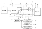
- the power transmission device is for transmitting or blocking the driving force by the engine (drive source) of an automobile (vehicle) to a wheel (driving wheel), and as shown in FIGS. 1 and 2, Torque converter 1, clutch means 3, selection means 4, first drive shaft 5, second drive shaft 6, damper mechanism 7, third clutch means 8, slip ratio calculation means for first clutch means 25 mainly includes a torque converter slip ratio calculation means 26 and a second clutch means slip ratio calculation means 27.
- the power transmission apparatus includes a speed sensor Y1 as an input-side measurement unit, a speed sensor Y2 as an output-side measurement unit, and a speed sensor Y3 as an input-side measurement unit for the second clutch unit. And a speed sensor Y4 capable of detecting the vehicle speed.
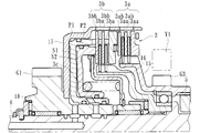
- FIG. 1 is a longitudinal sectional view showing the main part of the power transmission device according to the present embodiment
- FIG. 2 is a schematic view schematically showing the power transmission device according to the present embodiment.
- the torque converter 1 and the transmission 2 are disposed in the middle of the power transmission system from the engine E as a drive source of the vehicle to the wheels (drive wheels D), among which
- a transmission A is disposed in the transmission 2.
- reference numeral 11 denotes an input shaft extended from the engine E
- reference numeral 9 denotes an output shaft extended to the transmission A.
- the torque converter 1 has a torque amplification function of amplifying torque from the engine E and transmitting it to the transmission 2.
- the driving force of the engine E is transmitted to be rotatable about an axis and liquid (Hydraulic fluid) in a fluid-tight state, the pump P formed on the torquer cover 1a side and rotating with the torquer cover 1a, and facing the pump P at the torquer cover 13 side It mainly comprises a rotatably arranged turbine T.
- the input shaft 11 is connected to the torque converter cover 13 via the cover member 12. Then, when the input shaft 11 is rotated by the driving force of the engine E and the cover member 12, the torque converter covers 13 and 1a and the pump P are rotated, the rotational torque is amplified to the turbine T side via the liquid (hydraulic oil) Being transmitted while being Then, when the torque is amplified and the turbine T rotates, the first drive shaft 5 splined with the turbine T rotates, and the torque is transmitted to the transmission 2.
- the "drive transmission system of the torque converter” in the present invention refers to the drive transmission system formed by the torque converter cover 1a, the pump P and the turbine T described above.
- reference numeral 10 denotes a mission case.
- the torque converter cover 13 is connected to the connecting member 14 via a damper mechanism 7 formed of a coil spring, and the connecting member 14 is spline-fitted to the outer peripheral surface of the second drive shaft 6.
- the first drive shaft 5 is made rotatable by the driving force of the engine E through the drive transmission system of the torque converter 1 and is connected to the first clutch means 3 a
- the second drive shaft 6 is It is directly rotatable by the driving force of the engine E without passing through the drive transmission system of the torque converter 1, and is connected to the second clutch means 3b.
- the first drive shaft 5 is a cylindrical member
- the second drive shaft 6 is rotatably disposed therein, and the rotation axes of these are equal. It is done. That is, the first drive shaft 5 and the second drive shaft 6 are formed concentrically.
- first drive shaft 5 is rotatable on the outside of the second drive shaft 6, and the second drive shaft 6 is rotatable on the inside of the first drive shaft 5.
- the first drive shaft 5 and the second drive shaft 6 can be independently rotated by selective operation of the clutch means 3.
- the clutch means 3 is operable when the automobile (vehicle) advances, and transmits the driving force of the engine E (drive source) to the wheels (drive wheel D) via the drive transmission system of the torque converter 1.
- the clutch means 3a and the second clutch means 3b for transmitting the driving force of the engine E (drive source) to the wheels (drive wheels D) without passing through the drive transmission system of the torque converter 1 are provided.
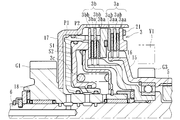
- the first clutch means 3a and the second clutch means 3b are formed with a plurality of drive side clutch plates 3aa, 3ba and driven side clutch plates 3ba, 3bb which are slidable in the lateral direction in FIG.
- the drive-side clutch plate 3aa is formed on the interlocking member 15 connected and interlocked with the first drive shaft 5, and the driven-side clutch plate 3ab is formed on the housing 17.
- the drive side clutch plate 3aa and the driven side clutch plate 3ab are alternately stacked. Thereby, the adjacent drive side clutch plate 3aa and the driven side clutch plate 3ab can be brought into pressure contact or separation.
- a state in which the first clutch means 3a is actuated and the drive side clutch plate 3aa and the driven side clutch plate 3ab are in pressure contact with each other is shown in FIG.
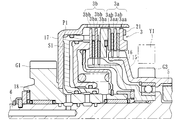
- the drive side clutch plate 3ba is formed on the interlocking member 16 linked and interlocked with the second drive shaft 6, and the driven side clutch plate 3bb is formed on the housing 17.
- the drive side clutch plate 3ba and the driven side clutch plate 3bb are alternately stacked. Thereby, the drive side clutch plate 3ba and the driven side clutch plate 3bb can be brought into pressure contact or separation.
- 7 shows a state in which the second clutch means 3b is actuated and the drive side clutch plate 3ba and the driven side clutch plate 3bb are in pressure contact with each other.
- separation means not only physical separation but also a state in which the pressure contact is released, and while the drive force is transmitted in the pressure contact state, the transmission of the drive force is interrupted in the separated state. Be done.
- the clutch means 3 corresponds to the first clutch means 3a, the second clutch means 3b, and the first clutch means 3a and the second clutch means 3b in the same casing 17.
- the first clutch means 3a or the second clutch means 3b can be optionally operated by controlling the hydraulic pressure for operating the hydraulic pistons P1 and P2 as well as having two hydraulic pistons P1 and P2.
- the hydraulic piston P1 moves to the right in the figure against the biasing force of the return spring 3c, and the tip thereof is
- the first clutch means 3a is pressed to bring the drive side clutch plate 3aa and the driven side clutch plate 3ab into pressure contact with each other.
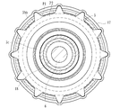
- the drive-side clutch plate 3ba and the driven-side clutch plate 3bb in the second clutch means 2b have an uneven shape formed on their respective peripheral edges, and the tip of the hydraulic piston P1 is inserted in the concave portion thereof. It is configured to be
- the hydraulic piston P2 is moved to the right in FIG. 3 against the biasing force of the return spring 3c by injecting hydraulic fluid into the hydraulic chamber S2 between the hydraulic piston P1 and the hydraulic piston P2, and the tip thereof is
- the second clutch means 3b is pressed to bring the drive side clutch plate 3ba and the driven side clutch plate 3bb into pressure contact with each other.
- the first clutch means 3a or the second clutch means 3b can be optionally operated by controlling the hydraulic pressure for operating the hydraulic pistons P1, P2.
- a housing 17 constituting the clutch means 3 is connected to an interlocking member 18 in which a gear G1 is formed, and the gear G1 meshes with a gear G2 formed on the output shaft 9.
- the driving force of the engine E transmitted by the first clutch means 3a or the second clutch means 3b reaches the interlocking member 18 through the housing 17 and is transmitted to the output shaft 9 .
- the selection means 4 injects hydraulic oil into the hydraulic chamber S1 or S2 at a predetermined pressure according to the state (vehicle speed, inclination angle of the vehicle body, etc.) of the vehicle (vehicle) at the time of forward movement (including start).
- the first clutch means 3a or the second clutch means 3b is optionally operated to drive the engine E (drive source) through the drive transmission system of the torque converter 1
- the force can be transmitted to the wheels (drive wheels D) or the drive force of the engine E (drive source) can be transmitted to the wheels (drive wheels D) without passing through the drive transmission system of the torque converter 1.
- the selection means 4 is formed, for example, in an ECU (not shown) for controlling the engine E.
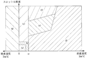
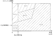
- a table as shown in FIG. 5 (with the vertical axis representing the throttle opening and the horizontal axis representing The clutch means 3 is operated on the basis of the vehicle speed.
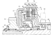
- both the first clutch means 3 a and the second clutch means 3 b are operated to transmit the driving force transmitted through the drive transmission system of the torque converter 1 and the torque converter 1. It is a mode in which the driving force transmitted without passing through the drive transmission system is transmitted to the wheel (driving wheel D) at a predetermined ratio.
- the ratio of the transmitted driving force can be arbitrarily set.
- both the first clutch means 3a and the second clutch means 3b are actuated to bring the drive side clutch plate 3aa and the driven side clutch plate 3ab, and the drive side clutch plate 3ba and the driven side clutch plate 3bb in pressure contact. Shown in 8.
- the first clutch means 3a or the second clutch means 3b can be selectively operated according to the table which can be compared with the state of the vehicle as described above, flat ground start, flat ground travel, downhill In traveling, the driving force of the engine E (driving source) is transmitted to the wheels (driving wheel D) without passing through the drive transmission system of the torque converter 1, and the driving of the torque converter 1 is performed during slope start, uphill travel
- the driving force of the engine E (drive source) can be transmitted to the wheels (drive wheels D) via the transmission system.
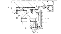
- the third clutch means 8 comprises a multi-plate clutch, and transmits the driving force of the engine E (drive source) to the wheels (drive wheels D) via the drive transmission system of the torque converter 1 when the vehicle reverses. belongs to. That is, when the shift lever provided on the vehicle is operated to set the R range (reverse), the idle gear is provided between the gear G3 formed on the interlocking member 15 and the gear G4 formed on the interlocking member 19 on the output shaft 9 side. (Not shown) intervenes in mesh, and the driving force of the engine E reaches the third clutch means 8.
- the third clutch means 8 has a housing 20 which can be interlocked with and interlocked with the output shaft 9, and the hydraulic piston P3 is provided in the housing 20. While being formed, the drive side clutch plate 8a and the driven side clutch plate 8b are alternately laminated. Thereby, the drive side clutch plate 8a and the driven side clutch plate 8b can be brought into pressure contact or separation by the operation of the hydraulic piston P3.
- FIG. 9 shows a state in which the third clutch means 8 is actuated and the drive side clutch plate 8a and the driven side clutch plate 8b are in pressure contact with each other.
- the selection means 4 is configured to operate the third clutch means 8 exclusively when the vehicle reverses. That is, when the shift lever of the vehicle is operated to set the R range (reverse), as shown by the table in FIG. 5, (g) R mode is set, and the engine E (the drive transmission system of the torque converter 1 is The drive power of the drive source is transmitted to the wheels (drive wheels D).
- the speed sensor Y1 as the input-side measurement means is a sensor capable of measuring the rotational speed of the input side of the first clutch means 3a in the middle of the power transmission system. Specifically, the rotational speed of the first drive shaft 5 It is supposed to be detectable.
- the speed sensor Y2 as the output side measuring means is a sensor capable of measuring the rotational speed on the output side of the first clutch means 3a in the middle of the power transmission system. Specifically, the rotational speed of the output shaft 9 is It is supposed to be detectable.
- the speed sensor Y3 as a drive source measuring means is a sensor capable of measuring the rotational speed of the drive source (engine E) of the vehicle, and the speed sensor Y4 is between the transmission A and the wheels (drive wheels D). And a sensor capable of detecting the rotational speed of the sensor.
- the speed sensors Y1 to Y4 are electrically connected to the first clutch slip ratio calculating means 25 and the torque converter slip ratio calculating means 26, respectively.
- the first clutch means slip ratio calculation means 25 calculates the slip of the first clutch means 3a from the difference or ratio between the rotational speed measured by the speed sensor Y1 and the rotational speed measured by the speed sensor Y2.
- the torque converter slip ratio calculation means 26 can calculate the torque from the difference or ratio between the rotational speed measured by the speed sensor Y3 and the rotational speed measured by the speed sensor Y1. It is assumed that the slip ratio of converter 1 can be calculated.
- the first clutch means slip ratio calculation means 25 and the torque converter slip ratio calculation means 26 are, as shown in FIG. 11, other than the selection means 4, slip ratio calculation means 27 for second clutch means described later, correction means 21.
- the control means 28 are formed in the CVT ECU mounted on the vehicle.
- the CVTECU is electrically connected to not only the speed sensors Y1 to Y4, but also brake switches, throttle opening sensors, position sensors, intake pressure sensors, atmospheric pressure sensors, engine water temperature sensors, TM (transmission) temperature sensors, etc. It is connected and it is comprised so that a detection signal may be transmitted from these sensors.
- control means 28 in the CVTECU as described above is electrically connected to the hydraulic control circuit, and the hydraulics and transmissions that operate the hydraulic pistons P1 to P3 through the hydraulic control circuit (for example, pulleys of continuously variable transmission Pressure) can be arbitrarily controlled.
- the first clutch means 3a by controlling the hydraulic pressure for operating the hydraulic piston P1 corresponding to the first clutch means 3a, the first clutch means 3a can be operated while being capacity-controlled, and the first The displacement control of the first clutch means 3a is performed based on the slip rates calculated by the first clutch means slip rate calculation means 25 or the torque converter slip rate calculation means 26 (including those by both). ing.
- the first clutch means 3a and the second clutch means 3b When the vehicle is in the stop state (specifically, the D range and the stop state by the brake) by the operation of the brake provided in the vehicle, the first clutch means 3a and the second clutch means 3b
- the driving force associated with the creep phenomenon of the torque converter 1 is made to be a wheel (driving wheel D) by operating the first clutch means 3a while controlling the displacement without controlling the first clutch means 3a when the brake operation is released. It is controlled to be transmitted to the side.
- invalid stroke clearance control that operates the hydraulic piston P1 to displace it just before the transmission of the driving force to the first clutch means 3a.
- the invalid stroke filling control is a slip calculated by the first clutch means slip ratio calculating means 25 or the torque converter slip ratio calculating means 26 (including both of them). It is supposed to be done based on the rate.
- the displacement control (hydraulic control for operating the piston P1) of the first clutch means 3a is performed by the first clutch means slip ratio calculation means 25 or the torque converter slip ratio calculation. Since the control is performed based on the slip ratio calculated by the means 26, the displacement control of the first clutch means 3a can be performed accurately.
- the first clutch means 3a and the second clutch means 3b do not operate, and the neutral state is established and the first clutch means 3a is released. Since the driving force associated with the creep phenomenon of the torque converter 1 is transmitted to the wheel side by operating while carrying out the capacity control, it is possible to improve the operability by transmitting the drive by the creep phenomenon.
- invalid stroke filling control is performed to operate the hydraulic piston P1 to displace the first clutch means 3a just before the transmission of the driving force is made. Responsiveness at the time of start from the state can be further improved.
- the invalid stroke filling control is performed based on the slip ratio calculated by the first clutch means slip ratio calculation means 25 or the torque converter slip ratio calculation means 26, the first clutch can be more accurately and surely performed.
- the invalid stroke filling control can be performed on the means 3a.
- the second clutch means input side measuring means capable of measuring the rotational speed on the input side of the second clutch means 3b in the middle of the power transmission system, and the second clutch means in the middle of the power transmission system.
- the second clutch means output side measuring means capable of measuring the rotational speed on the output side of 3b is provided, and the speed sensors Y3 and Y2 function as the second clutch means output side measuring means. It has become.
- the speed sensor Y3 functions as a drive source measuring means and also functions as an input side measuring means for the second clutch means
- the speed sensor Y2 functions as an output side measuring means and at the same time an output side for the second clutch means It is also configured to function as a measuring means.
- the second clutch means slip ratio calculating means 27 measures the rotational speed measured by the second clutch means input side measuring means (Y3) and the second clutch means output side measuring means (Y2).
- the slip ratio of the second clutch means 3b can be calculated from the difference or ratio with the calculated rotational speed.
- the hydraulic piston P2 corresponding to the second clutch means 3b is provided, and by controlling the hydraulic pressure for operating the hydraulic piston P2, the second clutch means 3b can be operated while being capacity-controlled.
- the displacement control of the second clutch means 3b is configured to be performed based on the slip rate calculated by the second clutch means slip rate calculation means 27.
- the operation of the second clutch means 3b is prohibited or restricted. That is, at the low temperature, the viscosity of the oil (working oil) for operating the hydraulic pistons P1 and P2 is changed, and there is a possibility that the responsiveness is deteriorated.
- the operation of the second clutch means 3b is prohibited or restricted.
- the responsiveness of the first clutch means 3a is also deteriorated, but the degree of deterioration of the responsiveness is lower than that of the second clutch means 3b, and the second clutch means 3b is operated. The deterioration of responsiveness can be suppressed to a low level as compared with the case of
- the first clutch means can be exclusively used rather than the second clutch means whose responsiveness is further deteriorated due to the low temperature, and power transmission
- the first clutch means can suppress the deterioration of the responsiveness of the device and, by restricting the operation of the second clutch means 3b at low temperatures, the responsiveness is further deteriorated due to the low temperature than the first clutch means Can be used with priority, and deterioration in responsiveness of the power transmission device can be suppressed.
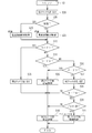
- the first clutch means 3a is turned off (S6), the second clutch means 3b is turned off (S7), and then the third clutch means 8 is turned off. (S8).
- the first clutch means 3a is turned off (S9), the second clutch means 3b is turned off (S10), and then the third clutch means is carried out at S11.
- S12 it is determined whether 8 is off, and if it is off, the process proceeds to S12, and it is determined whether the vehicle speed is larger than a predetermined value. When the vehicle speed is larger than the predetermined value, the process proceeds to S13, and the third clutch means 8 is turned off by the control by the inhibitor. If it is determined in S11 that the third clutch means is not off, and if it is determined in S12 that the vehicle speed is not greater than the predetermined value, the process proceeds to S14, and the third clutch means 8 is capacity-controlled.
- the process proceeds to S16, It is determined whether the temperature is low (the temperature detected by the TM temperature sensor is low). If it is determined that the temperature is not low, the process proceeds to S17, and a high temperature map as shown in FIG. 16 is searched and the high temperature map is taken into consideration to determine whether mode 1 should be made from the relationship between the vehicle speed and the throttle opening. Is determined (S18).
- mode 1 it is determined whether mode 2 should be set or not based on the relationship between the vehicle speed and the throttle opening by referring to the high temperature map (S19) and mode 2 should not be set Whether the mode should be mode 3 or not is determined from the relationship between the vehicle speed and the throttle opening degree with reference to the high temperature map (S20). If it is determined that the temperature is low in S16 and if it is determined that the mode 1 should be set in S18, the process proceeds to S22, the second clutch means 3b is turned off, and then the process proceeds to S26 to control the capacity of the first clutch means 3a. .
- step S21 If it is determined in S19 that mode 2 should be set, and if it is determined in step S21 that mode 3 should be set, the process proceeds to S20, the second clutch means 3b is capacity-controlled, and the process proceeds to S26. The capacity control of the clutch means 3a is performed. Furthermore, if it is determined that the mode 3 should not be set in S21, the process proceeds to S23, and after the second clutch means 3b is turned off, the high temperature map is taken into consideration to determine the mode from the relationship between the vehicle speed and the throttle opening. It is judged (S24) whether it should be 4 or not.
- S24 If it is determined in S24 that mode 4 should be set, it is determined whether or not the brake operation is performed (S25). If the brake operation is performed, the process proceeds to S27, and the first clutch means 3a is subjected to standby control (Ie, invalid stroke filling control). On the other hand, if it is determined that the mode 4 should not be set in S24 and if it is determined that the brake operation is not performed in S25, the process proceeds to S26, and the capacity control of the first clutch means 3a is performed.
- standby control Ie, invalid stroke filling control
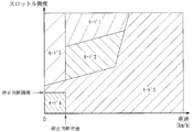
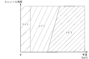
- the process proceeds to S29. Then, it is determined whether the temperature is low (the temperature detected by the TM temperature sensor is low). If it is determined that the temperature is not low, the process proceeds to S31, and the map for high temperature as shown in FIG. 18 is searched. If it is determined that the temperature is low, the process proceeds to S30 and the map for low temperature as shown in FIG. .
- the mode is determined based on the relationship between the vehicle speed and the throttle opening with reference to the high temperature map or the low temperature map.
- mode 1 should be set or not is determined from the relationship between the vehicle speed and the throttle opening degree by referring to the high temperature or low temperature map (S32). If mode 1 is not to be set, it is determined whether mode 2 should be set or not based on the relationship between the vehicle speed and the throttle opening degree by referring to the high temperature map (S33) and mode 2 should not be set Whether the mode should be mode 3 or not is determined from the relationship between the vehicle speed and the throttle opening degree taking into consideration the high temperature map or the low temperature map (S34). If it is determined in S32 that mode 1 should be set, the process proceeds to S35, and after the second clutch means 3b is turned off, the process proceeds to S40 and performs capacity control of the first clutch means 3a.
- the displacement control in the first clutch means 3a is calculated (S43), as shown in FIG. Thereafter, based on the friction coefficient obtained in S43, the target first clutch means pressure (the pressure of the targeted first clutch means 3b) is calculated (S44).
- the coefficient of friction in S43 is based on the temperature (temperature detected by the TM temperature sensor) of the hydraulic fluid in the hydraulic chamber S1 for operating the hydraulic piston P1 and the slip ratio calculated by the first clutch means slip ratio calculation means 25. It is calculated.
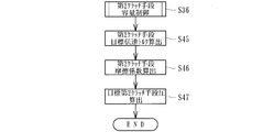
- the friction coefficient in the second clutch means 3b is calculated (S46)
- the target second clutch means pressure (the pressure of the targeted second clutch means 3b) is calculated (S47).
- the coefficient of friction in S47 is determined by the temperature of the hydraulic fluid in the hydraulic chamber S2 for operating the hydraulic piston P2 (the temperature detected by the TM temperature sensor) and the slip ratio calculated by the second clutch means slip ratio calculation means 27. It is calculated.
- the process proceeds to S50, and the previously determined target first clutch pressure is set as the current target first clutch pressure. On the other hand, if the predetermined time has elapsed in S48, the process proceeds to S49 to start feedback control, and it is determined whether the slip ratio of the first clutch means 3a has increased.
- FIG. 23 when the operation of the brake is released, the driving force accompanying the creep phenomenon of the torque converter 1 is transmitted to the wheel (driving wheel D) side by operating the first clutch means 3a while performing capacity control. After that, the second clutch means 3b is operated to start the vehicle, and the case where the throttle opening degree is a low opening degree is shown.
- FIG. 24 when the operation of the brake is released, the driving force accompanying the creep phenomenon of the torque converter 1 is transmitted to the wheel (driving wheel D) side by operating the first clutch means 3a while controlling the capacity. Thereafter, both the first clutch means 3a and the second clutch means 3b are operated to start the vehicle, and the case where the throttle opening degree is the middle opening degree is shown. Further, in FIG.
- the first clutch is obtained from the difference or ratio between the rotational speed measured by the input-side measurement means (speed sensor Y1) and the rotational speed measured by the output-side measurement means (speed sensor Y2). Since the slip rate of the means 3a is calculated, the friction coefficient (dynamic ⁇ and static ⁇ ) of the first clutch means 3a can be estimated based on the slip rate, and clutch control for the first clutch means 3a is easy and It can be done correctly.
- the slip ratio of the torque converter 1 is calculated from the difference or ratio between the rotational speed measured by the drive source measurement means (speed sensor Y3) and the rotational speed measured by the input-side measurement means (speed sensor Y1). Therefore, the amplification state of the torque converter 1 can be grasped based on the slip ratio, and the transmission torque can be easily estimated.
- the drive transmission system of the torque converter 1 is selectively operated by optionally activating the first clutch means 3a or the second clutch means 3b according to the state of the vehicle at the time of forward movement including the time of start. Since the selection means 4 capable of transmitting the driving force of the engine E to the wheels or transmitting the driving force of the engine E to the wheels without passing through the drive transmission system of the torque converter 1 is provided, the power transmission system is complicated and It is possible to suppress an increase in size and to improve the starting performance by the torque amplification function of the torque converter 1 and to improve the power transmission efficiency during steady traveling.
- speed sensors Y2 and Y3 (of course, Y4 are the same) according to the present embodiment are generally provided for other purposes by vehicles such as automobiles, these sensors can be newly added by diverting them.
- the manufacturing cost can be reduced as compared with the installation of
- first drive shaft 5 and the second drive shaft 6 are formed concentrically, the first drive shaft 5 and the second drive shaft 6 are respectively extended (two are provided side by side In comparison to the above, the whole power transmission can be miniaturized. Furthermore, since the second drive shaft 6 is connected to the engine E (drive source) via the damper mechanism 7 capable of damping torque fluctuation, vibration of the engine E (drive source) transmitted to the second clutch means 3b Can be attenuated.
- the selection means 4 operates both of the first clutch means 3a and the second clutch means 3b according to the state of the vehicle (for example, in the case of (e) in the table of FIG.
- Driving force transmitted through the drive transmission system of the torque converter 1 and driving force transmitted without the drive transmission system of the torque converter 1 are transmitted to the wheels (drive wheels D) at a predetermined ratio. Therefore, it is possible to easily adjust the transmission power to the wheels (drive wheels D). Further, it is preferable to change the ratio of the driving force in the case where the torque amplification function of the torque converter 1 is used in a large amount and in the case where the slip of the torque converter 1 is avoided to improve the power transmission efficiency.
- the third clutch means 8 transmits the driving force of the engine E (drive source) to the wheels (driving wheels D) via the drive transmission system of the torque converter 1, and the selecting means 4 is used when the vehicle reverses. Since the third clutch means 8 is operated exclusively, it is possible to suppress an increase in the size of the power transmission device by using only the drive transmission system via the drive transmission system of the torque converter 1 in reverse traveling at a low frequency. .
- the clutch means 3 has a first clutch means 3a, a second clutch means 3b, and two hydraulic pistons P1, P2 corresponding to the first clutch means 3a and the second clutch means 3b in the same housing 17.
- first clutch means 3a or the second clutch means 3b can be optionally operated by controlling the hydraulic pressure for operating the hydraulic pistons P1 and P2, the entire power transmission apparatus is further simplified. And can be miniaturized.
- the transmission A in this embodiment comprises a continuously variable transmission (so-called CVT).
- CVT continuously variable transmission
- the drive source (engine E) of the vehicle is connected to the wheels (engine E).
- a continuously variable transmission 24 is interposed between the second clutch means 3b of the clutch means 3 and the wheel (drive wheel D) in the middle of the power transmission system leading to the drive wheel D).
- the continuously variable transmission 24 has two pulleys Q1 and Q2 and a belt V suspended therebetween, and the hydraulic control circuit 23 operates the movable sheaves of the pulleys Q1 and Q2 so as to be independent of each other.
- the diameter of the belt V suspension portion is changed to perform desired gear change.
- the continuously variable transmission 24 has a CVTECU 22 electrically connected to a brake switch of a brake pedal and a position sensor of a shift lever in a vehicle, an engine ECU and the like (all not shown), and the CVTECU 22
- the hydraulic control circuit 23 is performed.
- the hydraulic pistons P1 to P3 described above can be operated arbitrarily.
- the second clutch means 3b of the clutch means 3 combines the clutch for moving the vehicle forward and the clutch for transmitting the driving force of the engine E to the drive wheels D without passing through the drive transmission system of the torque converter 1.
- symbol F in the same figure has shown the differential gear which a vehicle comprises.
- the first drive shaft 5 and the second drive shaft 6 are formed concentrically, but may be separately provided separately.
- the third clutch means 8 when the vehicle reverses, the third clutch means 8 is operated exclusively, and the drive power of the engine E (drive source) is transmitted to the wheels (drive wheels D) via the drive transmission system of the torque converter 1.
- fourth clutch means capable of transmitting the driving force of the engine E (drive source) to the wheels (driving wheels D) without via the drive transmission system of the torque converter 1 is provided.
- the third clutch means 8 and the fourth clutch means may optionally be selected according to the state.
- the drive source is the engine E
- the present invention is not limited to this, and the internal combustion engine may of course be a motor in an electric car or a hybrid vehicle, for example.
- the selection means 4 is formed in ECUs, such as CVTECU, you may form in the microcomputer arrange
- a torque converter having a torque amplification function, first clutch means operable while the vehicle is moving forward, and first clutch means for transmitting the driving force of the drive source to the wheels via the torque converter drive transmission system, and drive transmission of the torque converter Clutch means having a second clutch means for transmitting the driving force of the drive source to the wheels without a system, and optionally the first clutch means or the second clutch means according to the state of the vehicle at the time of forward movement including start time
- selecting means capable of transmitting the drive power of the drive source to the wheel via the drive transmission system of the torque converter, or transmitting the drive power of the drive source to the wheel without the drive transmission system of the torque converter
- An input-side measurement means capable of measuring the rotational speed of the input side of the first clutch means in the middle of the power transmission system, and the first one in the middle of the power transmission system
- the difference or ratio between the output side measuring means capable of measuring the rotational speed on the output side of the latch means, the rotational speed measured by the input side measuring means, and the rotational speed measured
Landscapes
- Engineering & Computer Science (AREA)
- General Engineering & Computer Science (AREA)
- Mechanical Engineering (AREA)
- Physics & Mathematics (AREA)
- Fluid Mechanics (AREA)
- Hydraulic Clutches, Magnetic Clutches, Fluid Clutches, And Fluid Joints (AREA)
- Control Of Fluid Gearings (AREA)
Abstract
Description
トルコンタイプの発進方式の自動変速機では、発進時においてトルクコンバータが有するトルク増幅機能により発進性能の向上を図ることができるという技術的メリットがあるものの、例えば定常走行中においては、トルクコンバータのスリップにより動力伝達効率が低下してしまうという技術的デメリットがあった。
本実施形態に係る動力伝達装置は、自動車(車両)のエンジン(駆動源)による駆動力を車輪(駆動輪)に伝達又は遮断するためのものであり、図1及び図2に示すように、トルクコンバータ1と、クラッチ手段3と、選択手段4と、第1駆動シャフト5と、第2駆動シャフト6と、ダンパ機構7と、第3クラッチ手段8と、第1クラッチ手段用スリップ率算出手段25と、トルクコンバータ用スリップ率算出手段26と、第2クラッチ手段用スリップ率算出手段27とを主に有している。
メインの制御について、図12で説明する。まず、車両の変速操作装置がDレンジ(ドライブレンジ)であるか否かが判定され(S1)、Dレンジである場合は、DレンジのサブフローS3に移行するとともに、Dレンジでない場合は、S2にてRレンジ(リバースレンジ)か否か判定される。Rレンジである場合は、RレンジのサブフローS4に移行するとともに、Rレンジでない場合は、Nレンジ(ニュートラルレンジ)であると判定され、NレンジのサブフローS5に移行する。
2 トランスミッション
3 クラッチ手段
3a 第1クラッチ手段
3b 第2クラッチ手段
4 選択手段
5 第1駆動シャフト
6 第2駆動シャフト
7 ダンパ機構
8 第3クラッチ手段
9 出力軸
10 ミッションケース
11 入力軸
12 カバー部材
13 トルコンカバー
14 連結部材
15、16 連動部材
17 筐体
18、19 連動部材
20 筐体
21 補正手段
22 CVTECU
23 油圧制御回路
24 無段変速機
25 第1クラッチ手段用スリップ率算出手段
26 トルクコンバータ用スリップ率算出手段
27 第2クラッチ手段用スリップ率算出手段
28 制御手段
E エンジン(駆動源)
A 変速機
D 駆動輪(車輪)
P1~P3 油圧ピストン
Claims (10)
- 車両の駆動源から車輪に至る動力伝達系の途中に配設され、当該駆動源の駆動力を車輪に対して任意選択的に伝達又は遮断可能な動力伝達装置において、
トルク増幅機能を有するトルクコンバータと、
車両の前進時に作動可能とされるとともに、前記トルクコンバータの駆動伝達系を介して前記駆動源の駆動力を前記車輪に伝達させる第1クラッチ手段、及び前記トルクコンバータの駆動伝達系を介さず前記駆動源の駆動力を前記車輪に伝達させる第2クラッチ手段を有するクラッチ手段と、
発進時を含む前進時における車両の状態に応じて前記第1クラッチ手段又は第2クラッチ手段を任意選択的に作動させて、前記トルクコンバータの駆動伝達系を介して前記駆動源の駆動力を前記車輪に伝達させ、又は前記トルクコンバータの駆動伝達系を介さず前記駆動源の駆動力を前記車輪に伝達させ得る選択手段と、
前記動力伝達系の途中における前記第1クラッチ手段の入力側の回転速度を測定し得る入力側測定手段と、
前記動力伝達系の途中における当該第1クラッチ手段の出力側の回転速度を測定し得る出力側測定手段と、
前記入力側測定手段にて測定された回転速度と、前記出力側測定手段にて測定された回転速度との差又は比から当該第1クラッチ手段のスリップ率を算出する第1クラッチ手段用スリップ率算出手段と、
を備えたことを特徴とする動力伝達装置。 - 車両の駆動源における回転速度を測定し得る駆動源測定手段を具備するとともに、当該駆動源測定手段にて測定された回転速度と、前記入力側測定手段にて測定された回転速度との差又は比から前記トルクコンバータのスリップ率を算出するトルクコンバータ用スリップ率算出手段を備えたことを特徴とする請求項1記載の動力伝達装置。
- 前記第1クラッチ手段に対応する油圧ピストンを有するとともに、当該油圧ピストンを作動させる油圧を制御することにより、当該第1クラッチ手段を容量制御しつつ作動可能とされ、且つ、当該第1クラッチ手段の容量制御は、前記第1クラッチ手段用スリップ率算出手段又はトルクコンバータ用スリップ率算出手段にて算出されたスリップ率に基づき行われることを特徴とする請求項1又は請求項2記載の動力伝達装置。
- ブレーキの操作により車両が停止状態であるとき、前記第1クラッチ手段及び第2クラッチ手段が作動せず、ニュートラル状態とされるとともに、ブレーキの操作を解除した際に前記第1クラッチ手段を容量制御しつつ作動させることにより前記トルクコンバータのクリープ現象に伴う駆動力を前記車輪側に伝達させることを特徴とする請求項3記載の動力伝達装置。
- 前記ブレーキの操作により車両が停止状態であるとき、前記第1クラッチ手段に対し駆動力の伝達がなされる直前まで変位させるべく前記油圧ピストンを作動させる無効ストローク詰め制御を行わせることを特徴とする請求項4記載の動力伝達装置。
- 前記無効ストローク詰め制御は、前記第1クラッチ手段用スリップ率算出手段又はトルクコンバータ用スリップ率算出手段にて算出されたスリップ率に基づき行われることを特徴とする請求項5記載の動力伝達装置。
- 車両の駆動源から車輪に至る動力伝達系の途中に配設され、当該駆動源の駆動力を車輪に対して任意選択的に伝達又は遮断可能な動力伝達装置において、
トルク増幅機能を有するトルクコンバータと、
車両の前進時に作動可能とされるとともに、前記トルクコンバータの駆動伝達系を介して前記駆動源の駆動力を前記車輪に伝達させる第1クラッチ手段、及び前記トルクコンバータの駆動伝達系を介さず前記駆動源の駆動力を前記車輪に伝達させる第2クラッチ手段を有するクラッチ手段と、
発進時を含む前進時における車両の状態に応じて前記第1クラッチ手段又は第2クラッチ手段を任意選択的に作動させて、前記トルクコンバータの駆動伝達系を介して前記駆動源の駆動力を前記車輪に伝達させ、又は前記トルクコンバータの駆動伝達系を介さず前記駆動源の駆動力を前記車輪に伝達させ得る選択手段と、
前記動力伝達系の途中における前記第2クラッチ手段の入力側の回転速度を測定し得る第2クラッチ手段用入力側測定手段と、
前記動力伝達系の途中における当該第2クラッチ手段の出力側の回転速度を測定し得る第2クラッチ手段用出力側測定手段と、
前記第2クラッチ手段用入力側測定手段にて測定された回転速度と、前記第2クラッチ手段用出力側測定手段にて測定された回転速度との差又は比から当該第2クラッチ手段のスリップ率を算出する第2クラッチ手段用スリップ率算出手段と、
を備えたことを特徴とする動力伝達装置。 - 前記第2クラッチ手段に対応する油圧ピストンを有するとともに、当該油圧ピストンを作動させる油圧を制御することにより、当該第2クラッチ手段を容量制御しつつ作動可能とされ、且つ、当該第2クラッチ手段の容量制御は、前記第2クラッチ手段用スリップ率算出手段にて算出されたスリップ率に基づき行われることを特徴とする請求項7記載の動力伝達装置。
- 低温時においては、前記第2クラッチ手段の作動が禁止されることを特徴とする請求項1~8の何れか1つに記載の動力伝達装置。
- 低温時においては、前記第2クラッチ手段の作動が規制されることを特徴とする請求項1~8の何れか1つに記載の動力伝達装置。
Priority Applications (3)
| Application Number | Priority Date | Filing Date | Title |
|---|---|---|---|
| JP2010534688A JP5462800B2 (ja) | 2008-10-22 | 2009-10-21 | 動力伝達装置 |
| CN200980141944.8A CN102197236B (zh) | 2008-10-22 | 2009-10-21 | 动力传递装置 |
| US13/092,035 US8262539B2 (en) | 2008-10-22 | 2011-04-21 | Power transmitting apparatus |
Applications Claiming Priority (2)
| Application Number | Priority Date | Filing Date | Title |
|---|---|---|---|
| JP2008271644 | 2008-10-22 | ||
| JP2008-271644 | 2008-10-22 |
Related Child Applications (1)
| Application Number | Title | Priority Date | Filing Date |
|---|---|---|---|
| US13/092,035 Continuation US8262539B2 (en) | 2008-10-22 | 2011-04-21 | Power transmitting apparatus |
Publications (1)
| Publication Number | Publication Date |
|---|---|
| WO2010047095A1 true WO2010047095A1 (ja) | 2010-04-29 |
Family
ID=42119149
Family Applications (1)
| Application Number | Title | Priority Date | Filing Date |
|---|---|---|---|
| PCT/JP2009/005504 Ceased WO2010047095A1 (ja) | 2008-10-22 | 2009-10-21 | 動力伝達装置 |
Country Status (4)
| Country | Link |
|---|---|
| US (1) | US8262539B2 (ja) |
| JP (1) | JP5462800B2 (ja) |
| CN (1) | CN102197236B (ja) |
| WO (1) | WO2010047095A1 (ja) |
Cited By (2)
| Publication number | Priority date | Publication date | Assignee | Title |
|---|---|---|---|---|
| WO2016159343A1 (ja) * | 2015-04-03 | 2016-10-06 | 株式会社エフ・シー・シー | ハイブリッド車両の動力伝達装置 |
| CN110869632A (zh) * | 2017-05-18 | 2020-03-06 | 法雷奥离合器公司 | 双离合器机构的力传递构件和双离合器机构 |
Families Citing this family (7)
| Publication number | Priority date | Publication date | Assignee | Title |
|---|---|---|---|---|
| CN104246318B (zh) * | 2012-04-23 | 2016-10-05 | 加特可株式会社 | 车辆的起步控制装置及起步控制方法 |
| US9108621B2 (en) | 2012-05-07 | 2015-08-18 | Ford Global Technologies, Llc | Controlling powertrain components for hill-holding in a hybrid electric vehicle |
| CN105164448B (zh) * | 2013-03-19 | 2018-01-16 | 株式会社F.C.C. | 动力传递设备 |
| US9457659B2 (en) * | 2014-12-17 | 2016-10-04 | Gm Global Technology Operations, Llc | Transmission with integrated power take-off |
| CN106195255B (zh) * | 2016-07-06 | 2017-11-07 | 厦门大学 | 自动挡轮式装载机液力变矩器控制方法 |
| JP6782657B2 (ja) * | 2017-03-29 | 2020-11-11 | 本田技研工業株式会社 | クラッチ制御装置 |
| DE102018128961A1 (de) * | 2018-11-19 | 2020-05-20 | Schaeffler Technologies AG & Co. KG | Verfahren zur Ermittlung einer Kupplungskenngröße im Generatorbetrieb |
Citations (7)
| Publication number | Priority date | Publication date | Assignee | Title |
|---|---|---|---|---|
| JPS6424760U (ja) * | 1987-07-31 | 1989-02-10 | ||
| JPH05126252A (ja) * | 1991-10-25 | 1993-05-21 | Hitachi Ltd | 自動変速機用トルクコンバータ制御方法 |
| JP2003172380A (ja) * | 2001-12-10 | 2003-06-20 | Honda Motor Co Ltd | 動力伝達装置における摩擦係合要素の係合制御方法 |
| JP2004169843A (ja) * | 2002-11-21 | 2004-06-17 | Toyota Motor Corp | 摩擦係合装置のスリップ制御装置 |
| JP2007032663A (ja) * | 2005-07-26 | 2007-02-08 | Jatco Ltd | クラッチ制御装置及びクラッチ制御方法 |
| JP2007327533A (ja) * | 2006-06-06 | 2007-12-20 | Honda Motor Co Ltd | 車両用動力伝達装置 |
| JP2008082529A (ja) * | 2006-09-29 | 2008-04-10 | Isuzu Motors Ltd | 車両用動力伝達装置における変速時クラッチ制御装置 |
Family Cites Families (14)
| Publication number | Priority date | Publication date | Assignee | Title |
|---|---|---|---|---|
| JPH0624602Y2 (ja) * | 1987-10-08 | 1994-06-29 | 日産ディーゼル工業株式会社 | 車両用動力伝達装置 |
| JP2606453B2 (ja) * | 1990-12-10 | 1997-05-07 | トヨタ自動車株式会社 | 自動変速機の制御装置 |
| JP3299050B2 (ja) * | 1994-09-29 | 2002-07-08 | 株式会社エクセディ | 動力伝達機構 |
| JP3434383B2 (ja) * | 1995-03-14 | 2003-08-04 | 株式会社エクセディ | トルクコンバータ |
| DE10004186B4 (de) * | 1999-09-30 | 2013-03-07 | Volkswagen Ag | Mehrfach-Kupplungseinrichtung |
| DE10004286B4 (de) * | 1999-09-30 | 2010-10-14 | Zf Sachs Ag | Kupplungseinrichtung mit einer hydrodynamischen Kupplung und zumindest zwei Reibungskupplungen |
| KR100495757B1 (ko) * | 2001-02-26 | 2005-06-16 | 가부시끼가이샤 히다치 세이사꾸쇼 | 마스터 실린더 |
| DE10314324A1 (de) * | 2003-03-28 | 2004-10-07 | Zf Friedrichshafen Ag | Hydrodynamischer Wandler mit einer Primärkupplung |
| JP2005003193A (ja) | 2003-05-16 | 2005-01-06 | Toyota Motor Corp | 車両用ロックアップクラッチの制御装置 |
| JP2004353844A (ja) * | 2003-05-30 | 2004-12-16 | Toyota Motor Corp | 車両用自動変速機のニュートラル制御装置 |
| CN100520101C (zh) * | 2003-10-06 | 2009-07-29 | 博格华纳公司 | 用于动力传动且具有混合输出系统的多离合器系统 |
| JP4418404B2 (ja) * | 2005-03-09 | 2010-02-17 | ジヤトコ株式会社 | クラッチ制御装置及びクラッチ制御方法 |
| JP4179368B2 (ja) | 2006-09-29 | 2008-11-12 | いすゞ自動車株式会社 | 車両用動力伝達装置のクラッチ制御装置 |
| US7798299B2 (en) * | 2006-11-09 | 2010-09-21 | Gm Global Technology Operations, Inc. | Dual input clutch transmission with torque converter pump drive |
-
2009
- 2009-10-21 CN CN200980141944.8A patent/CN102197236B/zh not_active Expired - Fee Related
- 2009-10-21 WO PCT/JP2009/005504 patent/WO2010047095A1/ja not_active Ceased
- 2009-10-21 JP JP2010534688A patent/JP5462800B2/ja not_active Expired - Fee Related
-
2011
- 2011-04-21 US US13/092,035 patent/US8262539B2/en not_active Expired - Fee Related
Patent Citations (7)
| Publication number | Priority date | Publication date | Assignee | Title |
|---|---|---|---|---|
| JPS6424760U (ja) * | 1987-07-31 | 1989-02-10 | ||
| JPH05126252A (ja) * | 1991-10-25 | 1993-05-21 | Hitachi Ltd | 自動変速機用トルクコンバータ制御方法 |
| JP2003172380A (ja) * | 2001-12-10 | 2003-06-20 | Honda Motor Co Ltd | 動力伝達装置における摩擦係合要素の係合制御方法 |
| JP2004169843A (ja) * | 2002-11-21 | 2004-06-17 | Toyota Motor Corp | 摩擦係合装置のスリップ制御装置 |
| JP2007032663A (ja) * | 2005-07-26 | 2007-02-08 | Jatco Ltd | クラッチ制御装置及びクラッチ制御方法 |
| JP2007327533A (ja) * | 2006-06-06 | 2007-12-20 | Honda Motor Co Ltd | 車両用動力伝達装置 |
| JP2008082529A (ja) * | 2006-09-29 | 2008-04-10 | Isuzu Motors Ltd | 車両用動力伝達装置における変速時クラッチ制御装置 |
Cited By (5)
| Publication number | Priority date | Publication date | Assignee | Title |
|---|---|---|---|---|
| WO2016159343A1 (ja) * | 2015-04-03 | 2016-10-06 | 株式会社エフ・シー・シー | ハイブリッド車両の動力伝達装置 |
| JP2016196243A (ja) * | 2015-04-03 | 2016-11-24 | 株式会社エフ・シー・シー | ハイブリッド車両の動力伝達装置 |
| US10532648B2 (en) | 2015-04-03 | 2020-01-14 | Kabushiki Kaisha F.C.C. | Power transmission device for hybrid vehicle |
| CN110869632A (zh) * | 2017-05-18 | 2020-03-06 | 法雷奥离合器公司 | 双离合器机构的力传递构件和双离合器机构 |
| CN110869632B (zh) * | 2017-05-18 | 2022-05-10 | 法雷奥离合器公司 | 双离合器机构的力传递构件和双离合器机构 |
Also Published As
| Publication number | Publication date |
|---|---|
| CN102197236B (zh) | 2014-01-22 |
| CN102197236A (zh) | 2011-09-21 |
| US20110237389A1 (en) | 2011-09-29 |
| JP5462800B2 (ja) | 2014-04-02 |
| JPWO2010047095A1 (ja) | 2012-03-22 |
| US8262539B2 (en) | 2012-09-11 |
Similar Documents
| Publication | Publication Date | Title |
|---|---|---|
| JP5462800B2 (ja) | 動力伝達装置 | |
| JP5145185B2 (ja) | 動力伝達装置 | |
| US8718879B2 (en) | Work vehicle and method for controlling work vehicle | |
| WO2010107050A1 (ja) | 動力伝達装置 | |
| JP5536329B2 (ja) | 動力伝達装置 | |
| JP3738667B2 (ja) | 無段変速機の変速制御装置 | |
| JP3923777B2 (ja) | 油圧−機械式変速装置 | |
| JP2002174335A (ja) | 自動変速機の制御装置および制御方法 | |
| JP2007271282A (ja) | 流体継手を備えた車両の車両重量検出装置 | |
| JP2005337416A (ja) | 自動変速機の制御装置 | |
| JP2004257518A (ja) | 変速機の制御装置 | |
| JP6170459B2 (ja) | 前後進切替装置の制御装置および制御方法 | |
| JP2929046B2 (ja) | 連続可変変速機の変速制御装置 | |
| JP2002139125A (ja) | Hmt式トランスミッションを備えるトラクタの駆動モード切換機構 | |
| JP3543703B2 (ja) | トルクコンバータのスリップ制御装置 | |
| KR20210074786A (ko) | 전기차 변속 제어방법 및 전기차 변속기 | |
| JP2961316B2 (ja) | 連続可変変速機のライン圧制御方法 | |
| EP1312837B1 (en) | Shift control apparatus and method of transmission for vehicle | |
| JP2010156380A (ja) | 車両の制御装置 | |
| JP4735343B2 (ja) | 車両用無段変速装置の変速制御装置 | |
| JPH09210189A (ja) | 無段変速機の制御装置 | |
| JP3840079B2 (ja) | トロイダル型無段変速機のスリップ防止装置 | |
| JP4379065B2 (ja) | 無段変速装置 | |
| JP2007239900A (ja) | 自動変速機の制御装置 | |
| JP2000179669A (ja) | パワートレインの制御装置 |
Legal Events
| Date | Code | Title | Description |
|---|---|---|---|
| WWE | Wipo information: entry into national phase |
Ref document number: 200980141944.8 Country of ref document: CN |
|
| 121 | Ep: the epo has been informed by wipo that ep was designated in this application |
Ref document number: 09821795 Country of ref document: EP Kind code of ref document: A1 |
|
| WWE | Wipo information: entry into national phase |
Ref document number: 2010534688 Country of ref document: JP |
|
| NENP | Non-entry into the national phase |
Ref country code: DE |
|
| 122 | Ep: pct application non-entry in european phase |
Ref document number: 09821795 Country of ref document: EP Kind code of ref document: A1 |