WO2010041747A1 - オートテンショナ - Google Patents
オートテンショナ Download PDFInfo
- Publication number
- WO2010041747A1 WO2010041747A1 PCT/JP2009/067661 JP2009067661W WO2010041747A1 WO 2010041747 A1 WO2010041747 A1 WO 2010041747A1 JP 2009067661 W JP2009067661 W JP 2009067661W WO 2010041747 A1 WO2010041747 A1 WO 2010041747A1
- Authority
- WO
- WIPO (PCT)
- Prior art keywords
- coil spring
- base
- elastic body
- auto tensioner
- friction
- Prior art date
Links
Images


Classifications
-
- F—MECHANICAL ENGINEERING; LIGHTING; HEATING; WEAPONS; BLASTING
- F16—ENGINEERING ELEMENTS AND UNITS; GENERAL MEASURES FOR PRODUCING AND MAINTAINING EFFECTIVE FUNCTIONING OF MACHINES OR INSTALLATIONS; THERMAL INSULATION IN GENERAL
- F16H—GEARING
- F16H7/00—Gearings for conveying rotary motion by endless flexible members
- F16H7/08—Means for varying tension of belts, ropes, or chains
- F16H7/10—Means for varying tension of belts, ropes, or chains by adjusting the axis of a pulley
- F16H7/12—Means for varying tension of belts, ropes, or chains by adjusting the axis of a pulley of an idle pulley
- F16H7/1209—Means for varying tension of belts, ropes, or chains by adjusting the axis of a pulley of an idle pulley with vibration damping means
- F16H7/1218—Means for varying tension of belts, ropes, or chains by adjusting the axis of a pulley of an idle pulley with vibration damping means of the dry friction type
-
- F—MECHANICAL ENGINEERING; LIGHTING; HEATING; WEAPONS; BLASTING
- F16—ENGINEERING ELEMENTS AND UNITS; GENERAL MEASURES FOR PRODUCING AND MAINTAINING EFFECTIVE FUNCTIONING OF MACHINES OR INSTALLATIONS; THERMAL INSULATION IN GENERAL
- F16H—GEARING
- F16H7/00—Gearings for conveying rotary motion by endless flexible members
- F16H7/08—Means for varying tension of belts, ropes, or chains
- F16H2007/0802—Actuators for final output members
- F16H2007/081—Torsion springs
-
- F—MECHANICAL ENGINEERING; LIGHTING; HEATING; WEAPONS; BLASTING
- F16—ENGINEERING ELEMENTS AND UNITS; GENERAL MEASURES FOR PRODUCING AND MAINTAINING EFFECTIVE FUNCTIONING OF MACHINES OR INSTALLATIONS; THERMAL INSULATION IN GENERAL
- F16H—GEARING
- F16H7/00—Gearings for conveying rotary motion by endless flexible members
- F16H7/08—Means for varying tension of belts, ropes, or chains
- F16H7/0829—Means for varying tension of belts, ropes, or chains with vibration damping means
- F16H2007/084—Means for varying tension of belts, ropes, or chains with vibration damping means having vibration damping characteristics dependent on the moving direction of the tensioner
-
- F—MECHANICAL ENGINEERING; LIGHTING; HEATING; WEAPONS; BLASTING
- F16—ENGINEERING ELEMENTS AND UNITS; GENERAL MEASURES FOR PRODUCING AND MAINTAINING EFFECTIVE FUNCTIONING OF MACHINES OR INSTALLATIONS; THERMAL INSULATION IN GENERAL
- F16H—GEARING
- F16H7/00—Gearings for conveying rotary motion by endless flexible members
- F16H7/08—Means for varying tension of belts, ropes, or chains
- F16H2007/0889—Path of movement of the finally actuated member
- F16H2007/0893—Circular path
Definitions
- the present invention relates to an auto tensioner that keeps the belt tension moderate.
- Patent Document 1 JP 2006-097898A describes a belt tensioning device in which a torsion coil spring, a spring strip, and a damping sleeve are provided between a hub and a housing casing.
- this belt tensioning device one end of the torsion coil spring is in contact with the housing casing, and the other end is in contact with one end of the spring strip.
- the other end of the spring strip is in contact with a fixed part formed on a lid which is firmly connected to the hub, and a damping sleeve is arranged between the spring strip and the receiving casing.
- the torsion coil spring is preloaded with a radially expanding preload, which causes the damping sleeve to be pressed against the inside of the receiving casing by the radial expansion of the spring strip.
- a braking force is generated by further increasing the pressing force against the damping sleeve.
- Patent Document 2 JP62-002182B2
- a coil spring performs a rotating operation to press the spring support against the boss portion of the rotating member with a predetermined pressing force, thereby sliding between the spring support and the boss portion.
- a configuration has been disclosed in which dynamic friction occurs and thus the rotation of the rotation member is damped.
- the damping sleeve is simply sandwiched between the spring strip and the receiving casing by the radial expansion of the spring strip by preloading (the damping sleeve is Therefore, when the preload is not applied to the damping sleeve at all times, when the circumferential force is applied to the damping sleeve, the damping sleeve slides on the outer circumferential surface of the spring strip. . Even if the pressing force against the damping sleeve is properly adjusted by preloading, the pressing force may decrease with long-term use. As described above, when the pressing force on the damping sleeve is reduced, the damping sleeve becomes slippery in the circumferential direction, and the braking force is greatly reduced.
- an object of the present invention is to provide an auto tensioner that suppresses a decrease in braking force.
- an auto tensioner configured as follows. That is, the auto tensioner is rotatably supported with respect to the base, the rotation member to which the pulley around which the belt is wound can be attached, one end locked to the base, and the rotation member.
- a coil spring that biases the rotating member in one direction with respect to the base, one end locked to one of the rotating member and the base, and the other end that is a free end.
- An elastic body extending along the other inner peripheral surface of the rotating member and the base, and in contact with the other inner peripheral surface of the rotating member and the base and with respect to the elastic body. And a friction member coupled to the direction so as not to move relative to each other.
- the coil spring is disposed in a state of being compressed in the axial direction, and the friction member is pressed against one of the rotating member and the base by a repulsive force trying to expand in the axial direction.
- the above-mentioned “locking” includes those that are stopped by being in contact with each other, those that are locked by being hooked, and those that are fixed by an adhesive or welding while being in contact. .
- the above auto tensioner may be further configured as follows. That is, one end of the elastic body is sandwiched between the rotating member and one of the base and the coil spring in the circumferential direction. That is, the rotating member and the coil spring are strongly engaged in the circumferential direction by one-way urging of the coil spring with respect to the rotating member. Therefore, according to the above configuration, the rotating member and the coil spring can be attached to the rotating member without complicating the configuration. On the other hand, the end of the elastic body can be securely locked.
- the above auto tensioner may be further configured as follows. That is, a plurality of friction members are provided apart from each other along the extending direction of the elastic body. According to the above configuration, when the elastic body spreads by the rotation of the rotating member, it is possible to suppress the friction member from being damaged due to the difference between the tensile elastic modulus of the elastic body and the tensile elastic modulus of the friction member.
- the auto tensioner may be further configured as follows. That is, the friction member has an L-shaped cross section.
- the coil spring is received in the axial direction at a portion perpendicular to the axial direction.
- the elastic body is received in the radial direction at a portion parallel to the axial direction. Due to such a sharp shape, the displacement of the friction member in the circumferential direction with respect to the elastic body is prevented at a higher level.
- the freedom degree of design regarding the brake effect between a base and a rotation member is high.
- the above auto tensioner may be further configured as follows. That is, the elastic body and the friction member are locked by meshing the unevenness formed with each other.
- the above configuration contributes to prevention of deviation in the circumferential direction of the friction member with respect to the elastic body.
- the above auto tensioner may be further configured as follows. That is, the elastic body and the friction member are locked by either adhesion with an adhesive or brazing.
- the above configuration contributes to prevention of deviation in the circumferential direction of the friction member with respect to the elastic body.
- the above auto tensioner may be further configured as follows. That is, the friction member is made of synthetic resin, and the friction member and the elastic body are integrally formed. The above configuration contributes to prevention of deviation in the circumferential direction of the friction member with respect to the elastic body.
- the above auto tensioner may be further configured as follows. That is, a coil spring support member that suppresses the inclination of the posture of the coil spring in the vicinity of one end of the elastic body is further provided, and the coil spring support member is disposed between the friction member and the coil spring. That is, when stabilizing the posture of the coil spring in the vicinity of one end of the elastic body, the coil spring support member is simply placed between the friction member and the coil spring as compared with the case where the one end of the elastic body is crafted.
- the arrangement to be arranged is beneficial from the viewpoint of life and design flexibility in that the role sharing of required functions is accurately realized.
- the above auto tensioner may be further configured as follows. That is, the coil spring support member is fixed to the friction member. According to the above configuration, when a load is applied to the coil spring support member due to the displacement or deformation of the coil spring, the load is efficiently transmitted to the friction member. Therefore, the frictional force between the friction member and the base or the rotation member increases.
- the above auto tensioner may be further configured as follows. That is, the coil spring support member is arranged in the same direction as the direction of the load received from one of the rotating member and the base, with the end of the coil spring contacting the one end of the elastic body, with the center axis of the auto tensioner as a reference. According to the above configuration, since the coil spring support member is waiting for the initial inclination of the coil spring in the vicinity of one end of the elastic body, the inclination of the coil spring in the vicinity of one end of the elastic body is reduced. It can be suppressed efficiently.
- the above auto tensioner may be further configured as follows.
- the coil spring support member is disposed within a range of 70 ° to 110 ° from the end of the coil spring that contacts one end of the elastic body. According to the above configuration, since the coil spring support member is waiting for the initial inclination of the coil spring in the vicinity of one end of the elastic body, the inclination of the coil spring in the vicinity of one end of the elastic body is reduced. It can be suppressed efficiently.
- Elevated sectional view of the auto tensioner according to the first embodiment of the present invention 2-2 sectional view of FIG.
- Sectional drawing which shows 2nd embodiment of this invention Sectional drawing which shows 3rd embodiment of this invention
- Sectional drawing which shows 4th embodiment of this invention Sectional drawing which shows 5th embodiment of this invention
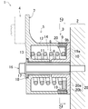
- FIG. 1 is an elevational sectional view of the auto tensioner according to the first embodiment of the present invention.
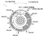
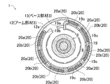
- 2 is a cross-sectional view taken along line 2-2 of FIG.
- FIG. 3 is a view for explaining the operation of the auto tensioner according to the first embodiment.
- An auto tensioner 1 shown in FIG. 1 is a device that is provided in an engine block 2 of an automobile and appropriately adjusts the tension of a transmission belt that transmits the power of an engine crankshaft to an auxiliary machine of the engine.
- the auto tensioner 1 can be mounted with a base member 3 (base) fixed to the engine block 2 and a pulley 4 around which a transmission belt (not shown) is wound while being rotatably supported by the base member 3.
- An arm member 5 (rotating member) and a coil spring 6 that urges the arm member 5 in one direction with respect to the base member 3 by engaging both ends of the arm member 5 with the base member 3 and the arm member 5, respectively.
- the biasing force by the coil spring 6 is converted into the tension of the transmission belt via the arm 7 of the arm member 5 and the pulley 4 that is rotatably attached to the arm 7.
- axial direction simply means a direction parallel to the rotation axis of the pulley 4.
- the base member 3 includes a base inner cylinder 8, a base outer cylinder 9 having a larger diameter than the base inner cylinder 8, and a donut-shaped bottom wall 10 connecting the base inner cylinder 8 and the base outer cylinder 9.
- the axial length of the base outer cylinder 9 is larger than the axial length of the base inner cylinder 8.
- the arm member 5 connects the boss portion 11, which is a cylindrical body having substantially the same diameter as the base inner tube 8, the arm outer tube 12 having a larger diameter than the boss portion 11, and the boss portion 11 and the arm outer tube 12.
- a doughnut-shaped lid wall 13 and an arm 7 extending further outward from the arm outer cylinder 12 are provided.
- the base inner cylinder 8 of the base member 3 and the boss portion 11 of the arm member 5 are arranged coaxially. Further, the base member 3 and the arm member 5 are combined so that the arm outer cylinder 12 of the arm member 5 covers the distal end portion of the base outer cylinder 9 of the base member 3 from the outer peripheral side, thereby accommodating the coil spring 6.
- a spring accommodating space 14 is formed. The spring accommodating space 14 is formed by the base inner cylinder 8 and the bottom wall 10 of the base member 3, the base outer cylinder 9, the arm outer cylinder 12 of the arm member 5, the lid wall 13, and the boss portion 11.
- One end of the coil spring 6 accommodated in the spring accommodating space 14 is locked to the base member 3, and the other end is locked to the arm member 5. Energize in the direction.
- “one direction” means a direction in which tension is applied to the transmission belt wound around the pulley 4.
- the coil spring 6 is locked to the base member 3 by a known method.
- the end of the coil spring 6 is fitted into a groove formed in the base member 3, or the bent end of the coil spring 6 is inserted into a locking hole extending in the radial direction or the axial direction formed in the base member 3.
- press-fitting for example, press-fitting.
- the end portion of the coil spring 6 is extended from the lid wall 13 toward the bottom wall 10, and the end portion of the coil spring 6 is brought into contact with the end portion of the coil spring 6 in the circumferential direction (see FIG. 2). Locked. The locking of the end of the coil spring 6 to the arm member 5 will be described in detail later.
- the base member 3 and the arm member 5 are supported with respect to the engine block 2 using bolts 16.
- the bolt 16 is passed through the base inner cylinder 8 of the base member 3 and the boss portion 11 of the arm member 5, and the tip of the bolt 16 is screwed into the engine block 2, whereby the base member 3
- the arm member 5 is supported by the engine block 2.
- the coil spring 6 accommodated in the spring accommodating space 14 is compressed in the axial direction.
- the spring accommodating space 14 accommodates a leaf spring 19 and a plurality of friction members 20 in the present embodiment.
- the plate spring 19 is a thin plate spring that extends in an arc shape along the inner peripheral surface of the outer cylinder 9 of the base member 3.
- the first end portion 19 a of the leaf spring 19 is bent at 90 degrees radially inward and is locked to the arm member 5. Specifically, the first end portion 19a is strongly sandwiched between the locking projection 15 of the arm member 5 and the coil spring 6 in the circumferential direction, so that the first end portion 19a is engaged with the locking projection 15 of the arm member 5. Stopped.
- the second end 19b of the leaf spring 19 is a free end. That is, the second end 19 b of the leaf spring 19 is not locked to the base member 3 or the arm member 5.
- the extending direction of the leaf spring 19 when the first end portion 19 a is used as a reference coincides with the direction in which the coil spring 6 is separated from the locking protrusion 15 of the arm member 5.
- the extension length of the leaf spring 19 is approximately 7/8.
- a plurality of friction members 20 are coupled to the leaf spring 19 at equal intervals so as to be in contact with the inner peripheral surface 9a of the base outer cylinder 9 of the base member 3 and incapable of relative movement in the circumferential direction.
- each friction member 20 has an L-shaped cross section, and a coil spring receiving portion 20 a perpendicular to the axial direction is disposed between the coil spring 6 and the lid wall 13 in the axial direction. Is done. Accordingly, the coil spring receiving portion 20a receives the self-elastic stretching force (repulsive force) of the coil spring 6 accommodated in the spring accommodating space 14 in a compressed state in the L-axis direction in the axial direction, and the lid wall of the arm member 5 13 is pressed against.
- the leaf spring receiving portion 20b that is parallel to the axial direction is disposed between the base outer cylinder 9 and the leaf spring 19 of the base member 3 in the radial direction, as shown in FIG. Therefore, the leaf spring receiving portion 20b receives the self-elastic expansion force of the leaf spring 19 accommodated in the spring accommodating space 14 in the radial direction in a state where it is slightly compressed in the radial direction.
- the plurality of friction members 20 are always in contact with the inner peripheral surface 9 a of the base outer cylinder 9 of the base member 3 by this self-elastic diameter expansion force.
- the plurality of friction members 20 are integrally formed with the leaf spring 19. Specifically, the leaf spring receiving portion 20 b of each friction member 20 is partially accommodated in a recess 19 c formed on the outer peripheral surface of the leaf spring 19, so that a strong force between the friction member 20 and the leaf spring 19 is obtained. Integrated molding is realized.
- the friction member 20 is made of a synthetic resin whose main component is nylon resin.
- the friction member 20 may be made of a synthetic resin whose main component is a polyacetal resin or a polyarylate resin, and any type can be used as long as it can be integrally formed with the leaf spring 19. Accordingly, the friction member 20 may be made of brass, plated brass, bronze, or plated bronze.
- the thickness of the coil spring receiving portion 20a of each friction member 20 slightly changes so as to just fill the gap between the coil spring 6 and the lid wall 13 in the steady state when the auto tensioner 1 is used. Specifically, in FIG. 2, the coil spring receiving portion 20 a of the friction member 20 gradually becomes thicker as it is arranged farther from the first end portion 19 a of the leaf spring 19. Accordingly, the self-elastic extension force acts evenly on the coil spring receiving portion 20a of each friction member 20, and therefore, uneven wear of the friction member 20 is suppressed.
- each friction member 20 receives the self-elastic extension force of the coil spring 6 in the axial direction, and thereby against the lid wall 13 of the arm member 5. It is pressed. That is, it is possible to prevent play of each friction member 20 by the leaf spring 19 by being sandwiched in the axial direction by the lid wall 13 of the arm member 5 and the coil spring 6.
- each friction member 20 is pressed from the base outer cylinder 9 of the base member 3 by receiving the self-elastic diameter expanding force of the leaf spring 19 in the radial direction. That is, when the base outer cylinder 9 of the base member 3 and the leaf spring 19 are clamped in the radial direction, play of each friction member 20 by the leaf spring 19 can be further prevented.
- the leaf spring 19 whose second end portion 19b is a free end is deformed into a slightly reduced diameter state, so that the locking projection 15 of the arm member 5 and the base outer cylinder 9 of the base member 3 are deformed.
- the friction torque acting between the two is small.
- This friction torque can be expressed as the following equation (1) according to ““ Spring ”, Industrial Research Co., Ltd., February 15, 1995, first edition, first edition, pp. 135-138.
- T1 is the above friction torque
- w is the force with which the locking projection 15 of the arm member 5 presses the leaf spring first end portion 19a of the leaf spring 19
- r is the radius of the leaf spring 19.
- ⁇ is a coefficient of dynamic friction between the base outer cylinder 9 of the base member 3 and the friction member 20
- ⁇ is a sum of circumferential lengths of the outer periphery of the friction member 20
- P is a torque associated with the initial tension of the coil spring 6.
- the auto tensioner 1 it occurs between the friction member 20 and the base member 3 when the arm member 5 rotates in the belt tension direction and when the arm member 5 rotates in the belt slack direction. So-called asymmetric damping is realized in which the frictional force (friction torque) is varied.
- the friction member 20 is pressed against the arm member 5 by the self-elastic stretching force (repulsive force) that the coil spring 6 tries to stretch in the axial direction, the installation state of the leaf spring 19 with respect to the arm member 5 is stabilized. Uneven wear of the friction member 20 is suppressed.
- the second end 19b of the leaf spring 19 is a free end and the friction member 20 is provided so as to come into contact with the inner peripheral surface 9a of the base outer cylinder 9 of the base member 3, the arm member 5 is attached to the belt.
- a so-called asymmetric damping is realized in which the frictional force generated between the friction member 20 and the base member 3 is different depending on whether it rotates in the direction of the belt or in the direction of slack in the belt.
- first end 19a of the leaf spring 19 is sandwiched between the arm member 5 and the coil spring 6 in the circumferential direction. That is, the arm member 5 and the coil spring 6 are strongly engaged in the circumferential direction by “biasing in one direction”. According to the above configuration, the first end portion 19a of the leaf spring 19 can be securely locked without complicating the configuration.
- a plurality of friction members 20 are provided apart from each other along the extending direction of the leaf spring 19. According to the above configuration, when the leaf spring 19 is spread by the rotation of the arm member 5, the friction member 20 can be prevented from being damaged due to the difference in tensile elastic modulus between the leaf spring 19 and the friction member 20. .
- the friction member 20 has an L-shaped cross section.
- the coil spring 6 is received in the axial direction by a coil spring receiving portion 20a that is perpendicular to the axial direction.
- the leaf spring 19 is received in the radial direction by the leaf spring receiving portion 20b which is parallel to the axial direction. According to the above configuration, the circumferential displacement of the friction member 20 with respect to the leaf spring 19 is prevented at a higher level. Further, since the L-shaped shape makes it easy to ensure the area of the coil spring receiving portion 20a that receives the coil spring 6 in the axial direction, the degree of freedom in designing the brake effect between the base member 3 and the arm member 5 is high.
- the friction member 20 is made of synthetic resin, and the friction member 20 and the leaf spring 19 are integrally formed.
- the above configuration contributes to prevention of deviation in the circumferential direction of the friction member 20 with respect to the leaf spring 19.
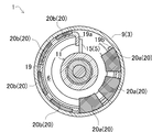
- FIG. 4 is a cross-sectional view showing a second embodiment of the present invention.
- the present embodiment will be described mainly with respect to differences from the first embodiment, and overlapping portions will be omitted as appropriate.
- the locking protrusion 15 of the arm member 5 according to the first embodiment is provided so as to protrude from the lid wall 13 of the arm member 5 shown in FIG. 1 toward the bottom wall 10.
- the locking projection 15 of the arm member 5 according to the present embodiment projects from the boss portion 11 of the arm member 5 shown in FIG. 1 toward the arm outer cylinder 12 as shown in FIG. (Third embodiment)
- FIG. 5 is a cross-sectional view showing a third embodiment of the present invention.
- the present embodiment will be described mainly with respect to differences from the first embodiment, and overlapping portions will be omitted as appropriate.
- each friction member 20 is partially accommodated in a recess 19 c formed on the outer peripheral surface of the leaf spring 19.
- a through hole 19d is formed instead of the recess 19c.
- each friction member 20 is formed with a protrusion 20c that can be fitted into the through hole 19d. Then, by engaging the protrusions 20 c formed on the friction member 20 with the through holes 19 d formed on the plate spring 19, the unevenness formed on each of the plate spring 19 and the friction member 20 is engaged. The leaf spring 19 and the friction member 20 are firmly coupled in the circumferential direction. Such engagement of the unevenness contributes to prevention of displacement in the circumferential direction of the friction member 20 with respect to the leaf spring 19. (Fourth embodiment)
- FIG. 6 is a three-dimensional view showing a fourth embodiment of the present invention.
- this embodiment will be described mainly with respect to differences from the first embodiment, and overlapping portions will be omitted as appropriate.
- the leaf spring 19 is formed with a saw blade-like saw blade portion 19e instead of the above-described recess 19c.
- each friction member 20 is formed with a saw blade portion 20d that meshes with the saw blade portion 19e without any gap. Then, the concave and convex portions formed on the leaf spring 19 and the friction member 20 are engaged with the saw blade portion 19e formed on the leaf spring 19 so that the saw blade portion 20d formed on the friction member 20 is engaged.
- the leaf spring 19 and the friction member 20 are firmly coupled in the circumferential direction. Such uneven engagement also contributes to prevention of displacement in the circumferential direction of the friction member 20 with respect to the leaf spring 19.
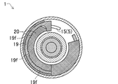
- FIG. 7 is a cross-sectional view showing a fifth embodiment of the present invention.
- the present embodiment will be described mainly with respect to differences from the first embodiment, and overlapping portions will be omitted as appropriate.
- the drawing of the coil spring 6 is omitted.
- a plurality of friction members 20 are arranged at predetermined intervals along the extending direction of the leaf spring 19.
- the friction member 20 similarly extends in an arc shape along the extending direction of the leaf spring 19.
- a plurality of small protrusions 19 f are formed on the inner peripheral surface of the leaf spring 19.
- the friction member 20 has a shape that sandwiches the leaf spring 19 in the radial direction while engaging with the plurality of small protrusions 19f. That is, the leaf spring 19 and the friction member 20 are firmly coupled to each other by the engagement using the small protrusions 19f and the relationship in which the leaf spring 19 is held in the radial direction by the friction member 20. It is preferable that the tensile elastic modulus of the leaf spring 19 and the tensile elastic modulus of the friction member 20 be as close as possible. According to this, it is possible to avoid the friction member 20 from being damaged due to a difference in tensile elastic modulus with the leaf spring 19. (Sixth embodiment)
- FIG. 8 is an elevational sectional view of the auto tensioner according to the sixth embodiment of the present invention.
- 9 is a cross-sectional view taken along line 9-9 in FIG.
- FIG. 10 is a three-dimensional view for explaining the operation of the auto tensioner according to the sixth embodiment.
- the present embodiment will be described mainly with respect to differences from the first embodiment, and overlapping portions will be omitted as appropriate.
- the base outer cylinder 9 of the base member 3 extends so as to overlap in the radial direction with respect to the base inner cylinder 8 and the boss portion 11.
- the base outer cylinder of the base member 3 is used.
- the arm outer cylinder 12 of the arm member 5 extends so as to overlap with the base inner cylinder 8 and the boss portion 11 in the radial direction.
- the base member 3 and the arm member 5 are combined so that the arm outer cylinder 12 of the arm member 5 covers the distal end portion of the base outer cylinder 9 of the base member 3 from the outer peripheral side.
- a groove 9b that accommodates the tip of the arm outer cylinder 12 of the arm member 5 is formed in the connection portion between the base outer cylinder 9 and the bottom wall 10 of the base member 3, and the arm outer cylinder of the arm member 5 is formed.
- the base member 3 and the arm member 5 are combined so that the base outer cylinder 9 of the base member 3 covers the front end portion of the base member 12 from the outer peripheral side.
- the spring accommodating space 14 is formed by the base inner cylinder 8 and the bottom wall 10 of the base member 3, the arm outer cylinder 12 of the arm member 5, the lid wall 13, and the boss portion 11.
- One end of the coil spring 6 accommodated in the spring accommodating space 14 is locked to the base member 3, and the other end is locked to the arm member 5, so that the arm member 5 is moved in one direction with respect to the base member 3.
- the end of the coil spring 6 is locked to the arm member 5 by a known method.
- the end of the coil spring 6 is fitted into a groove formed in the arm member 5, or the bent end of the coil spring 6 is inserted into a locking hole formed in the arm member 5 extending in the radial direction or the axial direction.
- press-fitting for example, press-fitting.
- the end portion of the coil spring 6 is extended by the locking projection 15 (see FIG. 9) that extends from the bottom wall 10 toward the lid wall 13 and contacts the end portion of the coil spring 6 in the circumferential direction. Is locked to the base member 3. The locking of the end of the coil spring 6 to the base member 3 will be described in detail later.
- the leaf spring 19 is a thin leaf spring that extends in an arc shape along the inner peripheral surface of the arm outer cylinder 12 of the arm member 5. Specifically, the leaf spring 19 extends in an arc shape along the inner peripheral surface 12 a of the arm outer cylinder 12 of the arm member 5.
- the first end portion 19 a of the leaf spring 19 is bent at 90 degrees radially inward and is locked to the base member 3. Specifically, the first end portion 19a is strongly sandwiched between the locking projection 15 of the base member 3 and the coil spring 6 in the circumferential direction, so that the first end portion 19a is engaged with the locking projection 15 of the base member 3. Stopped.
- the second end 19b of the leaf spring 19 is a free end. That is, the plate second end portion 19 b of the plate spring 19 is not locked to the base member 3 or the arm member 5.
- the extending direction of the leaf spring 19 when the first end portion 19 a is used as a reference coincides with the direction in which the coil spring 6 is separated from the locking protrusion 15 of the base member 3. In this embodiment, the extension length of the leaf spring 19 is approximately 7/8.
- a plurality of friction members 20 are coupled to the leaf spring 19 at equal intervals so as to be in contact with the inner peripheral surface 12a of the arm outer cylinder 12 of the arm member 5 and incapable of relative movement in the circumferential direction.
- each friction member 20 has an L-shaped cross section, and a coil spring receiving portion 20 a perpendicular to the axial direction is disposed between the coil spring 6 and the bottom wall 10 in the axial direction. Is done. Therefore, the coil spring receiving portion 20 a receives the self-elastic extension force (repulsive force) of the coil spring 6 compressed in the axial direction and accommodated in the spring accommodating space 14 in the axial direction, and is applied to the bottom wall 10 of the base member 3. Pressed.
- the leaf spring receiving portion 20b that is parallel to the axial direction is disposed so as to be sandwiched in the radial direction by the arm outer cylinder 12 and the leaf spring 19 of the arm member 5, as shown in FIG. Therefore, the leaf spring receiving portion 20b receives the self-elastic expansion force of the leaf spring 19 accommodated in the spring accommodating space 14 in the radial direction in a state where it is slightly compressed in the radial direction. Due to the presence of this self-elastic diameter expansion force, the plurality of friction members 20 are always in contact with the inner peripheral surface 12 a of the arm outer cylinder 12 of the arm member 5.
- the thickness of the coil spring receiving portion 20a of each friction member 20 slightly changes so as to just fill the gap between the coil spring 6 and the bottom wall 10 in a steady state when the auto tensioner 1 is used. Specifically, in FIG. 9, the coil spring receiving portion 20 a of the friction member 20 gradually becomes thicker as it is arranged farther from the first end portion 19 a of the leaf spring 19. Accordingly, the self-elastic stretching force acts evenly on the coil spring receiving portion 20a of each friction member 20, and therefore, uneven wear of the friction member 20 is suppressed.
- each friction member 20 receives the self-elastic extension force of the coil spring 6 in the axial direction, and thereby against the bottom wall 10 of the base member 3. It is pressed. That is, by being sandwiched in the axial direction by the bottom wall 10 of the base member 3 and the coil spring 6, play of each friction member 20 by the leaf spring 19 can be further prevented.
- each friction member 20 is pressed from the arm outer cylinder 12 of the arm member 5 by receiving the self-elastic expanding force of the leaf spring 19 in the radial direction. That is, by being clamped in the radial direction by the arm outer cylinder 12 of the arm member 5 and the plate spring 19, play of the friction members 20 by the plate spring 19 can be further prevented.
- the auto tensioner 1 it occurs between the friction member 20 and the arm member 5 when the arm member 5 rotates in the belt tension direction and when the arm member 5 rotates in the belt slack direction. So-called asymmetric damping is realized in which the frictional force (friction torque) is varied.
- the displacement in the circumferential direction of the friction member 20 with respect to the leaf spring 19 is prevented by the coupling that is not relatively movable in the circumferential direction. A decrease in braking force can be suppressed.
- the friction member 20 is pressed against the base member 3 by the self-elastic stretching force (repulsive force) that the coil spring 6 tries to stretch in the axial direction, the installation state of the plate spring 19 with respect to the base member 3 is stable. Thus, uneven wear of the friction member 20 is suppressed.
- the second end 19b of the leaf spring 19 is a free end, and the friction member 20 is provided so as to contact the inner peripheral surface 12a of the arm outer cylinder 12 of the arm member 5, so that the arm member 5 is in the belt tension direction.
- a so-called asymmetric damping is realized in which the frictional force generated between the friction member 20 and the arm member 5 is made different between when the belt is rotated in the belt slack direction.
- first end 19a of the leaf spring 19 is sandwiched between the base member 3 and the coil spring 6 in the circumferential direction. That is, since the coil spring 6 biases the base member 3 in one direction, the coil spring 6 is strongly engaged in the circumferential direction. According to the above configuration, the first end portion 19 a of the leaf spring 19 can be securely locked to the base member 3 without complicating the configuration.
- the leaf spring 19 and the friction member 20 may be locked by bonding with an adhesive or brazing. Such locking also contributes to prevention of deviation in the circumferential direction of the friction member 20 with respect to the leaf spring 19. (Seventh embodiment)
- FIG. 11 is a cross-sectional view showing a seventh embodiment of the present invention.
- the present embodiment will be described mainly with respect to differences from the first embodiment, and overlapping portions will be omitted as appropriate.
- the coil spring support member 30 that suppresses the inclination of the posture of the coil spring 6 in the vicinity of the first end portion 19a of the leaf spring 19. Is provided between the friction member 20 and the coil spring 6. That is, the coil spring support member 30 has a relationship of being sandwiched in the radial direction by the friction member 20 and the coil spring 6 in a cross-sectional view shown in FIG.
- the coil spring support member 30 is made of, for example, resin, and is fixed to the friction member 20 by appropriate bonding means.
- FIG. 11 shows a state in the auto tensioner 1 when the tension of the transmission belt wound around the pulley 4 of FIG. 1 varies within a predetermined range.
- the helical axis D of the helical coil spring 6 accommodated in the base outer cylinder 9 is usually the central axis of the auto tensioner 1 that can be specified based on the inner peripheral surface 9a of the base outer cylinder 9. Designed to approximately match C.
- the attitude of the coil spring 6 means an attitude of the coil spring 6 that can be observed by comparing the helical axis D of the coil spring 6 with the central axis C of the auto tensioner 1.
- the tension of the transmission belt is excessive as compared with the auto tensioner 1 according to the first embodiment, and the arm member 5 rotates counterclockwise in FIG.
- a frictional force is generated very quickly between the inner peripheral surface 9a of the base outer cylinder 9 and the friction member 20.
- the coil spring support member 30 is provided between the friction member 20 and the coil spring 6 in order to stabilize the posture of the coil spring 6 in the vicinity of the first end portion 19 a of the spring 19. installed.
- the role sharing of the required functions is accurately realized, and the life and design flexibility can be reduced. It is beneficial from a viewpoint.
- the auto tensioner 1 may be further configured as follows. That is, the coil spring support member 30 is fixed to the friction member 20. According to the above configuration, when some load is applied to the coil spring support member 30 due to the displacement or deformation of the coil spring 6, the load is efficiently transmitted to the friction member 20. The frictional force between the cylinder 9 and the inner peripheral surface 9a can be increased.
- the auto tensioner 1 may be further configured as follows. That is, the coil spring support member 30 is arranged in the same direction P ′ as the direction of the load P received by the end portion 6 y of the coil spring 6 from the arm member 5 with respect to the central axis C of the auto tensioner 1. According to the above configuration, the coil spring support member 30 is waiting for the initial inclination of the posture of the coil spring 6 in the vicinity of the first end portion 19 a of the plate spring 19. The inclination of the posture of the coil spring 6 in the vicinity of the end portion 19a can be efficiently suppressed.
- the auto tensioner 1 may be further configured as follows. That is, the coil spring support member 30 is disposed at a position of 90 ° from the end portion 6 y of the coil spring 6 in contact with the first end portion 19 a of the leaf spring 19. According to the above configuration, the coil spring support member 30 is waiting for the initial inclination of the posture of the coil spring 6 in the vicinity of the first end portion 19a of the plate spring 19. The inclination of the posture of the coil spring 6 in the vicinity of the one end portion 19a can be efficiently suppressed.
- the present invention is not limited to this, and the coil spring support member 30 has a wide range of 70 ° ⁇ ⁇ ⁇ 110 °. If it is within, the above highly efficient suppression effect is sufficiently exhibited.
- the coil spring support member 30 and the friction member 20 are separated from each other at the time of assembly and are fixed to each other at the time of assembly, but may be integrally formed.
- the number of coil spring support members 30 arranged is one, but the number of coil spring support members 30 arranged may be two or three or more. In this case, all the coil spring support members 30 are preferably disposed within the above preferable angle range, but only one of the coil spring support members 30 is disposed within the above preferable angle range, and the other coil springs are disposed.
- the support member 30 may be disposed outside the above preferred angle range.
- an auto tensioner that keeps the belt tension moderately and suppresses a decrease in braking force.
Abstract
Description
以下、図1及び図2を参照しつつ、本発明の第一実施形態に係るオートテンショナの構成を詳細に説明し、図1~3を参照しつつ、そのオートテンショナの作動を説明する。図1は、本発明の第一実施形態に係るオートテンショナの立面断面図である。図2は、図1の2-2線矢視断面図である。図3は、第一実施形態に係るオートテンショナの作動を説明するための図である。
上記の板バネ19は、ベース部材3の外筒9の内周面に沿って円弧状に延在する薄肉の板バネである。


(第二実施形態)
(第三実施形態)
(第四実施形態)
(第五実施形態)
(第六実施形態)
(第七実施形態)
(第八実施形態)
2 エンジンブロック
3 ベース部材
4 プーリ
5 アーム部材
6 コイルばね
7 アーム
9 ベース外筒
9a ベース外筒の内周面9a
15 係止突起
Claims (11)
- ベースと、
前記ベースに対して回動自在に支持されると共に、ベルトが巻き掛けられるプーリを取り付け可能な回動部材と、
前記ベースに係止された一端と、前記回動部材に係止された他端とを備え、前記ベースに対して前記回動部材を一方向に付勢するコイルばねと、
前記回動部材と前記ベースの一方に係止された一端と、自由端である他端とを備え、前記回動部材と前記ベースの他方の内周面に沿って延在する弾性体と、
前記回動部材と前記ベースの前記他方の内周面と接触するように、且つ、前記弾性体に対して周方向に相対移動不能に結合された摩擦部材と、を備え、
前記コイルばねは軸方向に圧縮された状態で配置され、軸方向に伸張しようとする反発力によって前記摩擦部材が前記回動部材と前記ベースの前記一方に対して押圧されるオートテンショナ。 - 前記弾性体の前記一端は、周方向において前記回動部材と前記ベースの前記一方と、前記コイルばねによって挟まれる請求項1に記載のオートテンショナ。
- 前記摩擦部材は、前記弾性体の延在方向に沿って互いに離隔して複数設けられている請求項1又は2に記載のオートテンショナ。
- 前記摩擦部材は、断面がL字形状を有し、軸方向に対して垂直となる部分で前記コイルばねを軸方向に受け、軸方向に対して平行となる部分で前記弾性体を径方向に受ける請求項1~3の何れかに記載のオートテンショナ。
- 前記弾性体と前記摩擦部材が、互いに形成された凹凸の噛み合わせによって係止される請求項1~4の何れかに記載のオートテンショナ。
- 前記弾性体と前記摩擦部材が、接着剤による接着及びロウ付けのいずれかによって係止された請求項1~5の何れかに記載のオートテンショナ。
- 前記摩擦部材が合成樹脂製であり、前記摩擦部材と前記弾性体とが一体に成形される請求項1~6の何れかに記載のオートテンショナ。
- 前記弾性体の前記一端近傍における前記コイルばねの姿勢の傾きを抑えるコイルばね支持部材をさらに備え、前記コイルばね支持部材は摩擦部材とコイルばねの間に配置される請求項1~7の何れかに記載のオートテンショナ。
- 前記コイルばね支持部材は前記摩擦部材に固着される請求項8に記載のオートテンショナ。
- 前記コイルばね支持部材は前記オートテンショナの中心軸を基準とし、前記弾性体の前記一端と当接する前記コイルばねの端部が、前記回動部材と前記ベース部材の前記一方から受ける荷重の方向と同一方向に配置される請求項8又は9に記載のオートテンショナ。
- 前記コイルばね支持部材は、前記弾性体の前記一端と当接する、前記コイルばねの端部から70°~110°の範囲内に配置される請求項8又は9に記載のオートテンショナ。
Priority Applications (5)
| Application Number | Priority Date | Filing Date | Title |
|---|---|---|---|
| CN200980140314.9A CN102177367B (zh) | 2008-10-10 | 2009-10-09 | 自动张紧器 |
| CA2739573A CA2739573C (en) | 2008-10-10 | 2009-10-09 | Auto-tensioner |
| BRPI0920350-8A BRPI0920350B1 (pt) | 2008-10-10 | 2009-10-09 | tracionador automático |
| EP09819280.0A EP2333376B1 (en) | 2008-10-10 | 2009-10-09 | Automatic tensioner |
| US13/122,780 US8678965B2 (en) | 2008-10-10 | 2009-10-09 | Auto-tensioner |
Applications Claiming Priority (4)
| Application Number | Priority Date | Filing Date | Title |
|---|---|---|---|
| JP2008-263942 | 2008-10-10 | ||
| JP2008263942 | 2008-10-10 | ||
| JP2009-129041 | 2009-05-28 | ||
| JP2009129041A JP5276520B2 (ja) | 2008-10-10 | 2009-05-28 | オートテンショナ |
Publications (1)
| Publication Number | Publication Date |
|---|---|
| WO2010041747A1 true WO2010041747A1 (ja) | 2010-04-15 |
Family
ID=42100693
Family Applications (1)
| Application Number | Title | Priority Date | Filing Date |
|---|---|---|---|
| PCT/JP2009/067661 WO2010041747A1 (ja) | 2008-10-10 | 2009-10-09 | オートテンショナ |
Country Status (7)
| Country | Link |
|---|---|
| US (1) | US8678965B2 (ja) |
| EP (1) | EP2333376B1 (ja) |
| JP (1) | JP5276520B2 (ja) |
| CN (1) | CN102177367B (ja) |
| BR (1) | BRPI0920350B1 (ja) |
| CA (1) | CA2739573C (ja) |
| WO (1) | WO2010041747A1 (ja) |
Cited By (3)
| Publication number | Priority date | Publication date | Assignee | Title |
|---|---|---|---|---|
| WO2011138101A1 (de) * | 2010-05-03 | 2011-11-10 | Schaeffler Technologies Gmbh & Co. Kg | Spannvorrichtung |
| WO2012147957A1 (ja) * | 2011-04-28 | 2012-11-01 | 三ツ星ベルト株式会社 | オートテンショナ |
| JP2013533947A (ja) * | 2010-06-22 | 2013-08-29 | デイコ アイピー ホールディングス,エルエルシー | ラジアルダンパ機構、およびベルトテンショナに使用したラジアルダンパ機構 |
Families Citing this family (14)
| Publication number | Priority date | Publication date | Assignee | Title |
|---|---|---|---|---|
| JP2013015166A (ja) * | 2011-07-01 | 2013-01-24 | Mitsuboshi Belting Ltd | オートテンショナ |
| JP5918043B2 (ja) * | 2012-06-25 | 2016-05-18 | 三ツ星ベルト株式会社 | オートテンショナ |
| JP5865789B2 (ja) * | 2012-06-28 | 2016-02-17 | 三ツ星ベルト株式会社 | オートテンショナ |
| ITTO20131032A1 (it) * | 2013-12-17 | 2015-06-18 | Dayco Europe Srl | Tenditore per una trasmissione a cinghia |
| JP6162162B2 (ja) * | 2014-02-18 | 2017-07-12 | 三ツ星ベルト株式会社 | オートテンショナ |
| JP6367128B2 (ja) * | 2015-01-27 | 2018-08-01 | バンドー化学株式会社 | オートテンショナ |
| US9618099B2 (en) * | 2015-07-13 | 2017-04-11 | Gates Corporation | Tensioner with secondary damping |
| WO2018003746A1 (ja) * | 2016-06-27 | 2018-01-04 | 三ツ星ベルト株式会社 | 補機駆動ベルトシステムに備わるオートテンショナ |
| JP6527550B2 (ja) | 2016-06-27 | 2019-06-05 | 三ツ星ベルト株式会社 | 補機駆動ベルトシステムに備わるオートテンショナ |
| CN107768939B (zh) * | 2017-11-22 | 2023-07-07 | 浙江锦豪电器有限公司 | 一种可调节弹起式地插 |
| US10883575B2 (en) * | 2018-01-03 | 2021-01-05 | Gates Corporation | Tensioner |
| US11168767B2 (en) * | 2018-10-23 | 2021-11-09 | Gates Corporation | Tensioner |
| DE102020004335A1 (de) * | 2020-07-20 | 2022-01-20 | Muhr Und Bender Kg | Riemenspannvorrichtung und Riementrieb mit einer solchen Riemenspannvorrichtung |
| JP2023115634A (ja) * | 2022-02-08 | 2023-08-21 | Ntn株式会社 | 補機ベルト用オートテンショナ、および補機駆動ベルトシステム |
Citations (7)
| Publication number | Priority date | Publication date | Assignee | Title |
|---|---|---|---|---|
| JPS622182B2 (ja) | 1981-07-08 | 1987-01-19 | Ritensu Otomooteibu Inc | |
| JPH0783295A (ja) * | 1993-09-20 | 1995-03-28 | Bando Chem Ind Ltd | オートテンショナ |
| JP2003254399A (ja) * | 2002-02-28 | 2003-09-10 | Mitsuboshi Belting Ltd | オートテンショナ |
| JP2004270858A (ja) * | 2003-03-11 | 2004-09-30 | Gates Unitta Asia Co | スプリングシートおよびオートテンショナ |
| JP2006097898A (ja) | 2004-09-28 | 2006-04-13 | Muhr & Bender Kg | ベルト引張装置 |
| JP2008263942A (ja) | 2007-04-24 | 2008-11-06 | Binan Shokken:Kk | 混合茶 |
| JP2009129041A (ja) | 2007-11-21 | 2009-06-11 | Yamatake Corp | 傾向監視システム、傾向監視装置、及び傾向監視方法 |
Family Cites Families (10)
| Publication number | Priority date | Publication date | Assignee | Title |
|---|---|---|---|---|
| US5632697A (en) | 1995-12-18 | 1997-05-27 | The Gates Corporation | Damping mechanism for a tensioner |
| US6609988B1 (en) * | 2001-05-24 | 2003-08-26 | The Gates Corporation | Asymmetric damping tensioner belt drive system |
| DE10131916A1 (de) * | 2001-07-05 | 2003-01-23 | Muhr & Bender Kg | Spanneinrichtung für Zugmittel, insbesondere Riemenspanneinrichtung |
| JP3502625B2 (ja) * | 2001-07-27 | 2004-03-02 | ゲイツ・ユニッタ・アジア株式会社 | オートテンショナ |
| US6612408B2 (en) | 2001-09-17 | 2003-09-02 | The Gates Corporation | Frictional damping strut |
| US6592482B2 (en) | 2001-10-22 | 2003-07-15 | The Gates Corporation | Tensioner |
| DE102006017287B4 (de) * | 2006-04-12 | 2021-03-25 | Litens Automotive Gmbh | Spanner für einen Endlostrieb |
| DE102007015676A1 (de) * | 2007-03-31 | 2008-10-02 | Schaeffler Kg | Spannvorrichtung eines Zugmitteltriebs |
| US8157682B2 (en) * | 2009-07-17 | 2012-04-17 | The Gates Corporation | Tensioner |
| JP5627621B2 (ja) * | 2011-04-28 | 2014-11-19 | 三ツ星ベルト株式会社 | オートテンショナ |
-
2009
- 2009-05-28 JP JP2009129041A patent/JP5276520B2/ja active Active
- 2009-10-09 CN CN200980140314.9A patent/CN102177367B/zh active Active
- 2009-10-09 EP EP09819280.0A patent/EP2333376B1/en active Active
- 2009-10-09 CA CA2739573A patent/CA2739573C/en active Active
- 2009-10-09 BR BRPI0920350-8A patent/BRPI0920350B1/pt active IP Right Grant
- 2009-10-09 US US13/122,780 patent/US8678965B2/en active Active
- 2009-10-09 WO PCT/JP2009/067661 patent/WO2010041747A1/ja active Application Filing
Patent Citations (7)
| Publication number | Priority date | Publication date | Assignee | Title |
|---|---|---|---|---|
| JPS622182B2 (ja) | 1981-07-08 | 1987-01-19 | Ritensu Otomooteibu Inc | |
| JPH0783295A (ja) * | 1993-09-20 | 1995-03-28 | Bando Chem Ind Ltd | オートテンショナ |
| JP2003254399A (ja) * | 2002-02-28 | 2003-09-10 | Mitsuboshi Belting Ltd | オートテンショナ |
| JP2004270858A (ja) * | 2003-03-11 | 2004-09-30 | Gates Unitta Asia Co | スプリングシートおよびオートテンショナ |
| JP2006097898A (ja) | 2004-09-28 | 2006-04-13 | Muhr & Bender Kg | ベルト引張装置 |
| JP2008263942A (ja) | 2007-04-24 | 2008-11-06 | Binan Shokken:Kk | 混合茶 |
| JP2009129041A (ja) | 2007-11-21 | 2009-06-11 | Yamatake Corp | 傾向監視システム、傾向監視装置、及び傾向監視方法 |
Non-Patent Citations (2)
| Title |
|---|
| "Spring", 15 February 1995, KOGYO CHOSAKAI PUBLISHING CO., LTD |
| See also references of EP2333376A4 * |
Cited By (5)
| Publication number | Priority date | Publication date | Assignee | Title |
|---|---|---|---|---|
| WO2011138101A1 (de) * | 2010-05-03 | 2011-11-10 | Schaeffler Technologies Gmbh & Co. Kg | Spannvorrichtung |
| US9005061B2 (en) | 2010-05-03 | 2015-04-14 | Schaeffler Technologies AG & Co. KG | Tensioning device |
| JP2013533947A (ja) * | 2010-06-22 | 2013-08-29 | デイコ アイピー ホールディングス,エルエルシー | ラジアルダンパ機構、およびベルトテンショナに使用したラジアルダンパ機構 |
| WO2012147957A1 (ja) * | 2011-04-28 | 2012-11-01 | 三ツ星ベルト株式会社 | オートテンショナ |
| US9206888B2 (en) | 2011-04-28 | 2015-12-08 | Mitsuboshi Belting Ltd. | Auto-tensioner |
Also Published As
| Publication number | Publication date |
|---|---|
| US20110201466A1 (en) | 2011-08-18 |
| JP2010112549A (ja) | 2010-05-20 |
| EP2333376B1 (en) | 2013-05-29 |
| CA2739573A1 (en) | 2010-04-15 |
| CA2739573C (en) | 2016-02-23 |
| US8678965B2 (en) | 2014-03-25 |
| BRPI0920350B1 (pt) | 2019-11-19 |
| JP5276520B2 (ja) | 2013-08-28 |
| CN102177367B (zh) | 2014-03-12 |
| BRPI0920350A2 (pt) | 2016-03-08 |
| EP2333376A4 (en) | 2012-04-18 |
| EP2333376A1 (en) | 2011-06-15 |
| CN102177367A (zh) | 2011-09-07 |
Similar Documents
| Publication | Publication Date | Title |
|---|---|---|
| WO2010041747A1 (ja) | オートテンショナ | |
| JP2010112549A5 (ja) | ||
| US9829081B2 (en) | Tensioner for engine with large and stable damping and minimum deflection o f shaft | |
| US7951030B2 (en) | Tensioner | |
| JP6774859B2 (ja) | オートテンショナ | |
| JP6162162B2 (ja) | オートテンショナ | |
| US11434980B2 (en) | Tensioner lever | |
| JP3916973B2 (ja) | オートテンショナ | |
| JP7311781B2 (ja) | テンショナレバー | |
| US9982760B2 (en) | Tensioner for engine with large and stable damping and minimum deflection of shaft | |
| US20090186727A1 (en) | Tensioner | |
| WO2015125691A1 (ja) | オートテンショナ | |
| WO2003052295A1 (fr) | Tensionneur | |
| JP5521203B2 (ja) | オートテンショナ | |
| JP7345256B2 (ja) | オートテンショナ | |
| JP2017122470A (ja) | オートテンショナ | |
| JP2013015166A (ja) | オートテンショナ | |
| JP5016534B2 (ja) | オートテンショナ | |
| JP4981567B2 (ja) | オートテンショナ | |
| JP7112941B2 (ja) | オートテンショナ | |
| JP3009811B2 (ja) | オートテンショナ | |
| JP3424737B2 (ja) | オートテンショナ |
Legal Events
| Date | Code | Title | Description |
|---|---|---|---|
| WWE | Wipo information: entry into national phase |
Ref document number: 200980140314.9 Country of ref document: CN |
|
| 121 | Ep: the epo has been informed by wipo that ep was designated in this application |
Ref document number: 09819280 Country of ref document: EP Kind code of ref document: A1 |
|
| WWE | Wipo information: entry into national phase |
Ref document number: 2739573 Country of ref document: CA |
|
| WWE | Wipo information: entry into national phase |
Ref document number: 2500/DELNP/2011 Country of ref document: IN |
|
| WWE | Wipo information: entry into national phase |
Ref document number: 13122780 Country of ref document: US Ref document number: 2009819280 Country of ref document: EP |
|
| NENP | Non-entry into the national phase |
Ref country code: DE |
|
| ENP | Entry into the national phase |
Ref document number: PI0920350 Country of ref document: BR Kind code of ref document: A2 Effective date: 20110411 |