WO2010041658A1 - Procédé de production de particule de mélange de carbonitrures ou de particule de mélange d'oxycarbonitrures, et leur utilisation - Google Patents
Procédé de production de particule de mélange de carbonitrures ou de particule de mélange d'oxycarbonitrures, et leur utilisation Download PDFInfo
- Publication number
- WO2010041658A1 WO2010041658A1 PCT/JP2009/067411 JP2009067411W WO2010041658A1 WO 2010041658 A1 WO2010041658 A1 WO 2010041658A1 JP 2009067411 W JP2009067411 W JP 2009067411W WO 2010041658 A1 WO2010041658 A1 WO 2010041658A1
- Authority
- WO
- WIPO (PCT)
- Prior art keywords
- carbonitride
- metal
- mixture particles
- particles
- group
- Prior art date
Links
Images
Classifications
-
- B—PERFORMING OPERATIONS; TRANSPORTING
- B01—PHYSICAL OR CHEMICAL PROCESSES OR APPARATUS IN GENERAL
- B01J—CHEMICAL OR PHYSICAL PROCESSES, e.g. CATALYSIS OR COLLOID CHEMISTRY; THEIR RELEVANT APPARATUS
- B01J27/00—Catalysts comprising the elements or compounds of halogens, sulfur, selenium, tellurium, phosphorus or nitrogen; Catalysts comprising carbon compounds
- B01J27/24—Nitrogen compounds
-
- H—ELECTRICITY
- H01—ELECTRIC ELEMENTS
- H01M—PROCESSES OR MEANS, e.g. BATTERIES, FOR THE DIRECT CONVERSION OF CHEMICAL ENERGY INTO ELECTRICAL ENERGY
- H01M4/00—Electrodes
- H01M4/86—Inert electrodes with catalytic activity, e.g. for fuel cells
- H01M4/90—Selection of catalytic material
- H01M4/9075—Catalytic material supported on carriers, e.g. powder carriers
-
- B—PERFORMING OPERATIONS; TRANSPORTING
- B01—PHYSICAL OR CHEMICAL PROCESSES OR APPARATUS IN GENERAL
- B01J—CHEMICAL OR PHYSICAL PROCESSES, e.g. CATALYSIS OR COLLOID CHEMISTRY; THEIR RELEVANT APPARATUS
- B01J37/00—Processes, in general, for preparing catalysts; Processes, in general, for activation of catalysts
- B01J37/34—Irradiation by, or application of, electric, magnetic or wave energy, e.g. ultrasonic waves ; Ionic sputtering; Flame or plasma spraying; Particle radiation
- B01J37/349—Irradiation by, or application of, electric, magnetic or wave energy, e.g. ultrasonic waves ; Ionic sputtering; Flame or plasma spraying; Particle radiation making use of flames, plasmas or lasers
-
- B—PERFORMING OPERATIONS; TRANSPORTING
- B82—NANOTECHNOLOGY
- B82Y—SPECIFIC USES OR APPLICATIONS OF NANOSTRUCTURES; MEASUREMENT OR ANALYSIS OF NANOSTRUCTURES; MANUFACTURE OR TREATMENT OF NANOSTRUCTURES
- B82Y30/00—Nanotechnology for materials or surface science, e.g. nanocomposites
-
- C—CHEMISTRY; METALLURGY
- C01—INORGANIC CHEMISTRY
- C01B—NON-METALLIC ELEMENTS; COMPOUNDS THEREOF; METALLOIDS OR COMPOUNDS THEREOF NOT COVERED BY SUBCLASS C01C
- C01B21/00—Nitrogen; Compounds thereof
- C01B21/082—Compounds containing nitrogen and non-metals and optionally metals
- C01B21/0828—Carbonitrides or oxycarbonitrides of metals, boron or silicon
-
- H—ELECTRICITY
- H01—ELECTRIC ELEMENTS
- H01M—PROCESSES OR MEANS, e.g. BATTERIES, FOR THE DIRECT CONVERSION OF CHEMICAL ENERGY INTO ELECTRICAL ENERGY
- H01M4/00—Electrodes
- H01M4/86—Inert electrodes with catalytic activity, e.g. for fuel cells
- H01M4/90—Selection of catalytic material
- H01M4/9008—Organic or organo-metallic compounds
-
- H—ELECTRICITY
- H01—ELECTRIC ELEMENTS
- H01M—PROCESSES OR MEANS, e.g. BATTERIES, FOR THE DIRECT CONVERSION OF CHEMICAL ENERGY INTO ELECTRICAL ENERGY
- H01M4/00—Electrodes
- H01M4/86—Inert electrodes with catalytic activity, e.g. for fuel cells
- H01M4/90—Selection of catalytic material
- H01M4/9016—Oxides, hydroxides or oxygenated metallic salts
-
- H—ELECTRICITY
- H01—ELECTRIC ELEMENTS
- H01M—PROCESSES OR MEANS, e.g. BATTERIES, FOR THE DIRECT CONVERSION OF CHEMICAL ENERGY INTO ELECTRICAL ENERGY
- H01M4/00—Electrodes
- H01M4/86—Inert electrodes with catalytic activity, e.g. for fuel cells
- H01M4/90—Selection of catalytic material
- H01M4/9075—Catalytic material supported on carriers, e.g. powder carriers
- H01M4/9083—Catalytic material supported on carriers, e.g. powder carriers on carbon or graphite
-
- C—CHEMISTRY; METALLURGY
- C01—INORGANIC CHEMISTRY
- C01P—INDEXING SCHEME RELATING TO STRUCTURAL AND PHYSICAL ASPECTS OF SOLID INORGANIC COMPOUNDS
- C01P2002/00—Crystal-structural characteristics
- C01P2002/70—Crystal-structural characteristics defined by measured X-ray, neutron or electron diffraction data
- C01P2002/72—Crystal-structural characteristics defined by measured X-ray, neutron or electron diffraction data by d-values or two theta-values, e.g. as X-ray diagram
-
- C—CHEMISTRY; METALLURGY
- C01—INORGANIC CHEMISTRY
- C01P—INDEXING SCHEME RELATING TO STRUCTURAL AND PHYSICAL ASPECTS OF SOLID INORGANIC COMPOUNDS
- C01P2004/00—Particle morphology
- C01P2004/51—Particles with a specific particle size distribution
-
- C—CHEMISTRY; METALLURGY
- C01—INORGANIC CHEMISTRY
- C01P—INDEXING SCHEME RELATING TO STRUCTURAL AND PHYSICAL ASPECTS OF SOLID INORGANIC COMPOUNDS
- C01P2004/00—Particle morphology
- C01P2004/60—Particles characterised by their size
- C01P2004/64—Nanometer sized, i.e. from 1-100 nanometer
-
- H—ELECTRICITY
- H01—ELECTRIC ELEMENTS
- H01M—PROCESSES OR MEANS, e.g. BATTERIES, FOR THE DIRECT CONVERSION OF CHEMICAL ENERGY INTO ELECTRICAL ENERGY
- H01M8/00—Fuel cells; Manufacture thereof
- H01M8/10—Fuel cells with solid electrolytes
- H01M2008/1095—Fuel cells with polymeric electrolytes
-
- Y—GENERAL TAGGING OF NEW TECHNOLOGICAL DEVELOPMENTS; GENERAL TAGGING OF CROSS-SECTIONAL TECHNOLOGIES SPANNING OVER SEVERAL SECTIONS OF THE IPC; TECHNICAL SUBJECTS COVERED BY FORMER USPC CROSS-REFERENCE ART COLLECTIONS [XRACs] AND DIGESTS
- Y02—TECHNOLOGIES OR APPLICATIONS FOR MITIGATION OR ADAPTATION AGAINST CLIMATE CHANGE
- Y02E—REDUCTION OF GREENHOUSE GAS [GHG] EMISSIONS, RELATED TO ENERGY GENERATION, TRANSMISSION OR DISTRIBUTION
- Y02E60/00—Enabling technologies; Technologies with a potential or indirect contribution to GHG emissions mitigation
- Y02E60/30—Hydrogen technology
- Y02E60/50—Fuel cells
Definitions
- the present invention relates to a method for producing metal carbonitride mixture particles or carbonitride oxide mixture particles and use thereof.
- the metal carbonitride mixture particles or carbonitride oxide mixture particles obtained by the production method of the present invention can be applied to technical fields such as photocatalysts, solar cells, phosphors, and quantum dots.
- Carbonitrides are mainly used by being coated on the surface of metal tools in order to improve mechanical properties, particularly wear resistance and chipping properties.
- mechanical properties particularly wear resistance and chipping properties.
- studies are continuing to develop a composition with better mechanical stability.
- Carbonitride is expected to be applied not only to tools but also to electronic materials due to its excellent electronic conductivity and thermal stability.
- Patent Document 2 a method of synthesizing carbonitride as particles has been developed, but the obtained particles are as large as about 1 ⁇ m at a minimum, and are used for catalysts and electronic materials that require miniaturization. Is too big.
- Patent Document 3 discloses a method for producing nanoparticles of aluminum oxide using a laser pyrolysis method. However, a carbonitride mixture particle or a carbonitride oxide mixture particle of a group 4 or group 5 transition metal is disclosed. No manufacturing method is disclosed.
- An object of the present invention is to solve the above-mentioned problems and to provide a method capable of producing industrially useful carbonitride mixture particles or carbonitride oxide mixture particles with high quality.
- the present inventors have intensively studied to solve the above-mentioned problems, resulting in the present invention.
- the present invention relates to the following (1) to (18), for example.
- a method for producing metal carbonitride mixture particles or carbonitride oxide mixture particles a method for producing metal carbonitride mixture particles or carbonitride oxide mixture particles, wherein laser light is used as a heat source for heating .
- the carbonitride mixture particles are formed by heating with the first laser beam, and then the carbonitride mixture particles and the oxygen source are reacted by heating with the second laser beam to obtain carbonitride oxide mixture particles.
- the metal salt is at least one selected from the group consisting of metal chloride, metal bromide, metal iodide, metal oxychloride, metal oxybromide and metal oxyiodide.
- metal carbonitride mixture particles according to (1) to (5) wherein the metal salt is at least one selected from the group consisting of acetate, nitrate, sulfate, carbonate and ammonium carbonate Or the manufacturing method of carbonitride oxide mixture particles.
- carbon source is at least one selected from the group consisting of carbon fine powder, hydrocarbon, alcohol, ketone, aldehyde, carboxylic acid and nitrile.
- the nitrogen source is at least one selected from the group consisting of ammonia, nitrogen, hydrazine and nitrile Method for producing product mixture particles.
- the oxygen source is at least one selected from the group consisting of oxygen, water, alcohol, ketone, aldehyde and carboxylic acid Method for producing particles or carbonitride oxide mixture particles.
- a catalyst for a fuel cell comprising a metal carbonitride mixture particle or carbonitride oxide mixture particle obtained by the production method according to any one of (1) to (12).
- An electrode having a fuel cell catalyst layer and a porous support layer, wherein the fuel cell catalyst layer comprises the fuel cell catalyst according to (13) or (14).
- a membrane electrode assembly having a cathode, an anode, and an electrolyte membrane disposed between the cathode and the anode, wherein the cathode and / or the anode is an electrode according to (15) Membrane electrode assembly.
- a fuel cell comprising the membrane electrode assembly according to (16).
- a polymer electrolyte fuel cell comprising the membrane electrode assembly according to (16).
- carbonitride mixture particles or carbonitride oxide mixture particles having a particle size as small as 1 to 100 nm can be produced, and particles having a uniform particle size distribution and composition distribution can be obtained. Can do. These particles can exhibit excellent properties in various catalysts, particularly fuel cell catalysts.
- the surface area is increased by reducing the particle size, so that the catalytic performance is improved. Furthermore, since the particle size is small, it is easy to make a catalyst-ion exchange membrane composite material (MEA) by a coating method, and the contact area between each layer can be increased, so that a composite with low contact resistance can be made. .
- MEA catalyst-ion exchange membrane composite material
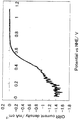
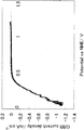
- FIG. 4 is a current-potential curve of a fuel cell electrode obtained in Example (4-2). 4 is a current-potential curve of a fuel cell electrode obtained in Comparative Example (1-2).
- the present invention mainly relates to a method for producing carbonitride mixture particles or carbonitride oxide mixture particles.
- carbonitride is one in which metal, carbon and nitrogen are detected at least when elemental analysis is performed, and oxygen is not substantially detected.
- Carbonitride oxide is subjected to at least elemental analysis. Sometimes metal, carbon, nitrogen and oxygen are detected.
- the carbonitride oxide mixture particles are part of the carbon nitride, in which oxygen is partially incorporated into the crystal lattice (hereinafter referred to as “intercrystalline oxygen-penetrating compound”) or contained in the carbonitride.
- the oxide of the metal element is formed to be a mixture of carbonitride and oxide, or is it a mixture of substances such as carbonitride, oxide, intercrystalline oxygen interpenetrating compound, or the same metal It is difficult to identify whether this carbonitride is a mixture of a compound having an oxide structure of the same metal and a compound in which part of oxygen of the oxide is partially substituted with carbon and nitrogen.
- carbonitride mixture particles particles of a mixture mainly composed of carbonitride are referred to as “carbonitride mixture particles”, and particles of a mixture mainly composed of carbonitride oxide are referred to as “carbonitride oxide mixture particles”.
- carbonitride oxide mixture particles particles of a mixture mainly composed of carbonitride are referred to as “carbonitride oxide mixture particles”.
- the carbonitride mixture particles or carbonitride oxide mixture particles also include the case where they are pure carbonitride particles or carbonitride oxide particles, respectively.
- the average particle diameter d of the particles synthesized in the present invention refers to the average primary particle diameter obtained from the formula (1) from the specific surface area obtained by the BET method, assuming that the particles are spherical.
- d is the average particle diameter (unit: nm)
- ⁇ is the true density of the particles (unit: g / cm 3 )
- S is the specific surface area m 2 / g of the particles.
- an organometallic compound, a metal salt or a compound thereof is used as a metal raw material compound.
- these raw materials are collectively referred to as “metal compound raw materials”.
- the method for producing metal carbonitride mixture particles or carbonitride oxide mixture particles of the present invention comprises a group 4 or group 5 transition metal organometallic compound, a metal salt or a mixture thereof and a nitrogen source, and optionally carbon.
- a laser beam is used as a heat source for heating in a manufacturing method of heating a reaction gas obtained by mixing a source and an oxygen source together with a diluent gas to obtain the carbonitride mixture particles or carbonitride oxide mixture particles of the metal It is characterized by that.
- This manufacturing method can be implemented using, for example, the following laser pyrolysis apparatus. [Overall configuration of laser pyrolysis apparatus 1] FIG.
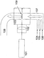
- FIG. 1 is a diagram schematically showing the configuration of a specific example of a laser pyrolysis apparatus used in the production method of the present invention.
- reference numeral 101 is a laser
- 102 is a condenser lens
- 103 is a chamber
- 104 is a carrier gas and oxygen source inlet
- 105 is a metal compound raw material and carbon source inlet
- 106 is a nitrogen source inlet
- 107 is a reaction.
- a gas inlet 108 is a product outlet
- 109 is a reaction section.
- a carrier gas is introduced from a carrier gas inlet 104, a metal compound raw material and a carbon source are introduced from a metal compound raw material and a carbon source inlet 105, and a nitrogen source is introduced from a nitrogen source inlet 106, which are reactive gases.
- the reaction gas is mixed at the introduction port 107 and supplied into the chamber 103.
- Laser light generated by the laser 101 passes through the condenser lens 102 and is irradiated to the reaction gas in the chamber 103.
- the part where the reaction gas is irradiated with the laser beam becomes the reaction part.
- the reaction gas is heated by laser light as a heat source, and carbonitride mixture particles are generated.
- the carbonitride mixture particles are carried out of the chamber 103 through the product outlet 108.
- each raw material is liquid at room temperature, it is necessary to heat it in advance in a quartz tube or the like and use it as a gas. In this case, it is necessary to raise the temperature of the carrier gas in advance and keep the entire production reaction system at the boiling point or higher. At this time, it is desirable to supply a raw material heated at a temperature exceeding the boiling point of the raw material by 20 ° C. or more.
- the raw material when the raw material is solid, it can be used as a raw material by being dispersed in a solvent and sprayed with a carrier gas using a two-fluid nozzle.
- the particles to be produced tend to have a smaller primary particle size and agglomerated particle size when synthesized from a gas raw material, and it is desirable that the present invention be achieved by a gas phase-gas phase reaction as much as possible.
- any conventionally known laser light can be used.
- CO 2 laser light is more preferable because a gas having absorption in the infrared region can efficiently absorb laser energy.
- the gas having absorption in the infrared region include ethylene, isopropyl alcohol, ammonia, silane, ozone, and sulfur hexafluoride. Since it becomes a nitriding source for producing carbonitride mixture particles or carbonitride oxide mixture particles, it is more preferable to use ammonia as a gas that absorbs laser light.
- the output of the laser is not particularly limited, but high temperature is necessary for the production of carbonitride mixture particles or carbonitride oxide mixture particles, and a high output laser is preferable for mass production.
- the laser output is preferably 100 W to 100 kW. There is no problem in using a laser having an output exceeding 100 kW, but the cost becomes high for industrial use. More preferably, they are 200 W or more and less than 10 kW, More preferably, they are 500 W or more and less than 5 kW.
- the carrier gas is introduced from the carrier gas inlet, mixed with the metal compound raw material, and introduced into the chamber.
- the flow rate can be controlled by adjusting the flow rate of the carrier gas.
- the carrier gas When the carrier gas is introduced into the furnace, it has a volume different from the standard state due to the relationship between the furnace temperature and pressure. However, in order to simplify the operation of the equipment, the operating conditions are generally controlled by the gas supply amount in the standard state.
- the carrier gas flow rate in the present invention is desirable because the shorter the average residence time obtained by dividing the chamber volume by the carrier gas flow rate, the smaller the carbonitride mixture particles or carbonitride oxide mixture particles that are generated. If it is too short, the metal compound raw material may be unreacted and discharged together with the product. For this reason, the average residence time is desirably 0.01 minutes or more and less than 500 minutes, more desirably 0.1 minutes or more and less than 200 minutes, and further preferably 0.5 minutes or more and less than 30 minutes.
- the metal contained in the metal compound raw material used in the production method of the present invention is a transition metal of Group 4 or Group 5 of the periodic table, and is preferably at least one selected from the group consisting of niobium, titanium and zirconium.
- the organometallic compound used as the metal compound raw material in the production method of the present invention is not particularly limited as long as it is an organometallic compound having absorption in the infrared region, for example, when CO 2 laser light is used as a heat source.
- alkoxides such as metal ethoxide, propoxide, butoxide, chelates such as acetylacetonate, complexes of cyclopentadienyl-like structure, organic acid esters, glycolate, oligomers in which polycondensation of alkoxide, alkyl A metal, metal carbonyl, etc. can be mentioned.
- niobium niobium methoxide, niobium butoxide, niobium ethoxide, niobium phenoxide, bis (methylcyclopentadienyl) niobium dichloride, cyclopentadienyl niobium tetrachloride, niobium 2-ethylhexanoate, tetrakis (2,2 , 6,6-tetramethyl-3,5-heptanedionato) niobium, dichlorotrimethylniobium, and the like.
- niobium ethoxide and niobium are preferred from the viewpoint of raw material cost and carbon-metal element balance. It is desirable to use butoxide.
- titanium titanium-propoxide, titanium-butoxide, titanium tetra-2-ethylhexoxide, titanium-propoxyoctylene glycolate, di-propoxy bis (acetylacetonato) titanium, propanedioxytitanium bis (ethylacetate) Acetate) tri-normal-butoxytitanium monostearate, di-iso-propoxytitanium-di-stearate, titanium stearate, di-iso-propoxytitanium-di-isostearate, (2-normal-butoxycarbonylbenzoyloxy) )
- Materials such as tributoxy titanium, di-normal-butoxy bis (triethanolaminato) titanium, titanium lactate, polyhydroxy titanium stearate, trimethyl titanium can be used.
- titanium ethoxide it is desirable to use titanium butoxide.
- zirconium zirconium-acetylacetone, zirconium ethoxide, zirconium (normal or tertiary) butoxide, zirconium propoxide, bis (cyclopentadienyl) dimethylzirconium, dimethylbis (tertiary-butylcyclopentadienyl) zirconium, Tetrabenzylzirconium, tetrakis (diethylamino) zirconium, tetrakis (ethylmethylamino) zirconium, tetrakis (2,2,6,6-tetramethyl-3,5-heptanedionato) zirconium, dichloride-bis (tertiary-butylcyclopenta) Dienyl) zirconium, bis (methylcyclopentadienyl) zirconium dichloride, bis (pentamethylcyclopentadienyl) zirconium dichloride, cyclopen
- metal salt used as the metal compound raw material in the production method of the present invention there is no particular limitation on the metal salt used as the metal compound raw material in the production method of the present invention.
- halides exemplified by niobium pentachloride, titanium tetrachloride, zirconium tetrachloride, niobium bromide, titanium bromide, zirconium bromide, niobium iodide, titanium iodide, zirconium iodide, etc., or these
- the intermediate hydrolyzate is niobium oxychloride, titanium oxychloride, zirconium oxychloride, niobium oxybromide, titanium oxybromide, zirconium oxybromide, niobium oxyiodide, titanium oxyiodide, zirconium oxyiodide, etc. Can do.
- Other usable metal salts include niobium acetate, titanium acetate, zirconium acetate, niobium nitrate, titanium nitrate, zirconium nitrate, niobium sulfate, titanium sulfate, zirconium sulfate, niobium carbonate, titanium carbonate, zirconium carbonate, carbonic acid.
- Ammonium zirconium and intermediate hydrolysates thereof such as titanyl sulfate can be mentioned.
- the metal compound raw material is introduced from the metal compound raw material inlet, and is introduced into the chamber while being mixed with the carrier gas. There is an optimum supply amount of the metal compound raw material, and if the supply amount is too large, unreacted raw material may remain in the product or the size of the particles may increase. On the other hand, when the supply amount is too small, there is a problem that the productivity of the system is lowered.
- the desired supply amount of the metal compound raw material depends on the output of the laser. However, when an output of 500 W or more and 5 kW is selected, the supply amount is desirably 0.5 mmol or more and 1000 mol or less per minute, and more desirably 1 mmol. It is 500 mmol or less, more preferably 3 mmol or more and 400 mmol or less.
- Carbon sources include carbon black, fine carbon such as activated carbon, hydrocarbons such as methane, ethane, propane, ethylene and acetylene, alcohols such as methanol, ethanol, propanol and butanol, ketones such as acetone, formaldehyde and acetaldehyde, etc. Aldehydes, carboxylic acids such as formic acid and acetic acid, and nitriles such as acetonitrile can be used.
- the carbon source is separately supplied as described above, it is desirable that the carbon source is supplied in an amount of 0.001 carbon molar equivalent / minute or more and 10 carbon molar equivalent / minute or less with respect to the laser output of 1000 W. Preferably it is 0.01 carbon molar equivalent / minute or more and 5 carbon molar equivalent or less, More preferably, it is 0.2 carbon molar equivalent / minute or more and 2 carbon molar equivalent or less.
- the optimal carbon molar equivalent changes in linear proportion to the laser output.
- the nitrogen source nitriles such as ammonia, nitrogen, hydrazine and acetonitrile are preferably used. It is more preferable to use ammonia because it has high reactivity and is relatively stable.
- the nitrogen source is introduced from the nitrogen source inlet and is introduced into the chamber in a state of being mixed with the carrier gas. When the nitrogen source is supplied as described above, it is desirable that the nitrogen source is supplied in an amount of 0.01 nitrogen molar equivalent / minute or more and 100 nitrogen molar equivalent / minute or less with respect to the laser output of 1000 W, and more preferably. Is preferably from 0.05 nitrogen molar equivalent / min to 10 nitrogen molar equivalent, more preferably from 0.1 carbon molar equivalent / minute to 5 nitrogen molar equivalent. However, the optimal nitrogen molar equivalent varies linearly with the laser output.
- oxygen atoms need to be introduced when producing carbonitrides.
- oxygen source oxygen, water, alcohols such as methanol, ethanol, propanol and butanol, ketones such as acetone, aldehydes such as formaldehyde and acetaldehyde, and carboxylic acids such as formic acid and acetic acid can be used.
- the oxygen source can be introduced from the carrier gas inlet 104 of the laser pyrolysis apparatus shown in FIG.
- the oxygen source is desirably supplied in an amount of 0.001 oxygen molar equivalent / minute or more and 10 oxygen molar equivalent / minute or less with respect to the laser output of 1000 W, and more preferably. Is preferably from 0.01 oxygen molar equivalent / minute to 5 oxygen molar equivalent, more preferably from 0.2 oxygen molar equivalent / minute to 2 oxygen molar equivalent.
- the optimal oxygen molar equivalent changes in linear proportion to the laser output.
- a reduced pressure atmosphere is preferable because the reaction gas can be easily introduced into the chamber and the product can be easily taken out.
- the pressure in the chamber is 1 to 700 Torr. If it is less than 1 Torr, the amount of reactive gas is not sufficient, and it is difficult to efficiently produce carbonitride particles or carbonitride oxide particles. In the range exceeding 700 Torr, it is difficult to achieve a reduced pressure atmosphere.
- the laser beam generated from the laser may be put into the chamber as it is, but it is preferable to use a condensing lens in order to raise the temperature more efficiently. Moreover, since energy can be concentrated only in the reaction part by using a condensing lens, there exists an effect which prevents the temperature rise of other parts. In particular, when a highly reactive gas such as ammonia is used, there is a high possibility of damaging the inner wall of the chamber and the glass window when the temperature is high, so it is preferable to avoid an increase in the temperature of these portions.
- a substance that phase-separates in a normal firing furnace using an electric furnace because the temperature rapidly decreases when it is slightly away from the condensing part where the laser beam is concentrated by the condensing lens.
- this apparatus using laser light it can be easily mixed.
- a solid solution of niobium, titanium, zirconium, or a solid solution with other metal components is prepared to improve the characteristics as a catalyst, it is a very effective means to use a condensing lens.
- any material can be used for the condensing lens as long as it has transparency in the infrared region, but it is preferable to use ZnSe, GaAS, or Ge. Furthermore, ZnSe is more preferable because it has the highest transmittance at a wavelength of 10.6 ⁇ m.
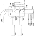
- FIG. 2 is a diagram schematically showing another configuration of the laser pyrolysis apparatus used in the manufacturing method of the present invention. This apparatus is an apparatus using two laser beams as heat sources. In FIG.
- reference numeral 201 denotes a first laser
- 202 denotes a first condenser lens
- 203 denotes a second laser
- 204 denotes a second condenser lens
- 205 denotes a chamber
- 206 denotes a first carrier gas inlet.
- 207 is a metal compound raw material inlet
- 208 is a carbon source inlet
- 209 is a nitrogen source inlet
- 210 is a reactive gas inlet
- 211 is a second carrier gas inlet
- 212 is an oxygen source inlet
- 213 is a reaction
- Reference numeral 214 denotes a product gas outlet
- 215 denotes a first reaction section
- 216 denotes a second reaction section.
- a carrier gas is introduced from the first carrier gas inlet 206, a metal compound raw material from the metal compound raw material 207, a carbon source from the carbon source inlet 208, and a nitrogen source from the nitrogen source inlet 209, These are mixed at the reaction gas inlet 210 to become the first reaction gas and supplied into the chamber 205.
- Laser light generated by the first laser 201 passes through the first condenser lens 202 and is irradiated to the first reaction gas in the chamber 205.
- the portion where the first reactive gas is irradiated with the laser light becomes the first reaction portion 215.
- the first reaction gas is heated by the laser beam that is a heat source in the reaction unit 215, and carbonitride mixture particles are generated in the first reaction gas.
- a carrier gas is introduced from the second carrier gas inlet 211 and an oxygen source is introduced from the oxygen source inlet 212, and these are mixed at the reactive gas inlet 213 to become a reactive gas, which is supplied into the chamber 205.
- the reactive gas supplied into the chamber 205 merges with the first reaction gas containing the carbonitride mixture particles to form a second reaction gas.
- Laser light generated by the second laser 203 is irradiated to the second reactive gas in the chamber 205 through the second condenser lens 204. A portion where the laser beam is irradiated to the second reaction gas becomes the second reaction portion 216.
- the second reaction gas is heated by a laser beam as a heat source, and carbonitride oxide mixture particles are generated.
- the carbonitride oxide mixture particles are carried out of the chamber 205 through the product outlet 214.
- the roles of the laser, the condenser lens, the chamber, the carrier gas inlet, the metal compound source gas inlet, the nitrogen source gas inlet, the reaction gas inlet, and the product outlet are basically the same as in FIG. .
- the present invention it is possible to synthesize oxycarbonitride mixed particles from an organometallic compound, metal salt or a mixture thereof in one step, but once a carbonitride mixture is produced from an organometallic compound, metal salt or a mixture thereof. Synthesize the particles and react the obtained carbonitride mixture particles with an oxygen source to synthesize the carbonitride oxide mixture particles to obtain a carbonitride oxide mixture particle having a uniform composition and high crystallinity Can be preferable.
- the minimum temperature for synthesizing carbonitride mixture particles and the minimum temperature for synthesizing carbonitride oxide mixture particles are different.
- the obtained substance may be sintered.
- the specific surface area of the particles may be reduced, the properties as particles may be reduced, or a crushing step may be required after production, which is not preferable.
- Heating by laser is required as a method for synthesizing carbonitride mixture particles or carbonitride oxide mixture particles because it can be rapidly cooled by applying the necessary amount of heat for the required time, but it is desirable to synthesize carbonitride mixture particles It is more preferable that the step of performing the step and the step of oxidizing the carbon nitride oxide mixture particles are separated in the furnace.
- reaction section 215 a carrier gas, a metal compound raw material, a carbon source and a nitrogen source are introduced and reacted in the same manner as in FIG. 1 to obtain carbonitride mixture particles.
- two or more kinds of metal compound raw materials may be introduced into the reaction unit 215 to produce carbonitride mixture particles containing a plurality of metals.
- the carbonitride mixture particles can be oxidized into carbonitride oxide mixture particles.
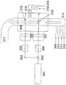
- FIG. 2 shows a schematic diagram when the laser beam generated from one laser is branched.
- reference numeral 301 is a laser
- 302 is a laser beam splitter
- 303 is a reflecting mirror
- 304 is a first attenuator
- 305 is a second attenuator
- 306 is a first condenser lens
- 307 is a second condenser.
- 308 is a chamber
- 309 is a first carrier gas inlet
- 310 is a metal compound raw material inlet
- 311 is a carbon source inlet
- 312 is a nitrogen source inlet
- 313 is a reactive gas inlet
- 314 is a second carrier gas inlet.
- a carrier gas inlet, 315 is an oxygen source inlet
- 316 is a reactive gas inlet
- 317 is a product outlet
- 318 is a first reaction section
- 319 is a second reaction section.
- oxygen or water As the oxygen source. This is because other organic compounds containing oxygen do not work effectively as an oxygen source at low temperatures, and the utilization rate of raw materials decreases. It is more desirable to use water than oxygen. This is because water is cheaper and the reaction rate is smaller than when oxygen is used, and it becomes easier to control the reaction of the entire furnace, and uniform oxycarbonitride mixture particles are produced. This is because it can be obtained.
- the composition ratio of the obtained sample was Ti 1.0 C 0.15 N 0.35 .
- Example 2 Using the laser pyrolysis apparatus shown in FIG. 2, carbonitride mixture particles were produced under the following conditions. In a chamber having a reaction volume of 2 cubic chambers, a nitrogen gas preheated to 200 ° C. as a carrier gas is 30,000 sccm, ammonia preheated to 200 ° C. is 7000 sccm as a nitrogen source, and is preheated to 200 ° C. as a metal compound raw material. Titanium ethoxide was flowed at 4 g (17.5 mmol) per minute.
- the laser beam generated at the output of the CO 2 laser 1200W was condensed on the first reaction unit using a condenser lens.
- the chamber pressure at this time was 200 Torr.
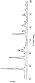
- the composition ratio of the obtained titanium carbonitride oxide mixture particles was Ti 1.00 C 0.08 N 0.04 O 1.40 , and the XRD pattern is shown in FIG. (Example 3)
- carbonitride mixture particles were produced under the following conditions. Niobium pre-heated to 200 ° C. as a metal compound raw material in a chamber having a reaction volume of 2 cubic meters, 30000 sccm of nitrogen preheated to 200 ° C. as a carrier gas, 21000 sccm of ammonia preheated to 200 ° C. as a nitrogen source Ethanol was flowed at a rate of 6 g (18.9 mmol) per minute.
- the laser beam generated at the output of the CO 2 laser 1200W was condensed on the first reaction unit using a condenser lens.
- the chamber pressure at this time was 200 Torr.
- Example 4-1 Using the laser pyrolysis apparatus shown in FIG. 2, carbonitride mixture particles were produced under the following conditions. Zirconium pre-heated to 200 ° C. as a metal compound raw material in a chamber having a reaction volume of 2 cubic meters, 30000 sccm of argon preheated to 200 ° C. as a carrier gas, 21000 sccm of ammonia preheated to 200 ° C.
- the chamber pressure at this time was 200 Torr.
- Example 4-3 Evaluation of oxygen reduction ability
- the catalytic ability (oxygen reduction ability) of the fuel cell electrode produced in Example 4-2 was evaluated by the following method.
- the produced fuel cell electrode was polarized in an oxygen atmosphere and a nitrogen atmosphere in a 0.5 mol / dm 3 sulfuric acid solution at a potential scanning rate of 30 mV and 5 mV / sec, and a current-potential curve was measured.
- a reversible hydrogen electrode in a sulfuric acid solution having the same concentration was used as a reference electrode.
- the potential at which a difference of 1.0 ⁇ A / cm 2 or more appears between the reduction current in the oxygen atmosphere and the reduction current in the nitrogen atmosphere was defined as the oxygen reduction start potential, and the difference between the two was defined as the oxygen reduction current.
- the catalytic ability (oxygen reducing ability) of the fuel cell electrode produced by this oxygen reduction starting potential and oxygen reducing current was evaluated.
- FIG. 5 shows a current-potential curve obtained by subtracting the current value in oxygen saturation obtained by the above measurement from the current value in nitrogen saturation, that is, a current-potential curve related to the oxygen reduction current.
- the fuel cell electrode produced in Example 4 had an oxygen reduction starting potential of 0.81 V (vs. NHE) and was found to have a high oxygen reducing ability.
- Comparative Example 1-1 Zirconium oxide (manufactured by Wako Pure Chemical Industries) 1.2g and carbon black (XC72, manufactured by Cabot) are mixed well, put into a boron nitride crucible, and in a nitrogen stream using a graphite furnace (High Multi 5000, manufactured by Fuji Denpa Kogyo). Was heated at 2000 ° C. for 3 hours to obtain a carbonitride mixture containing 1.1 g of zirconium.
- the obtained carbonitride mixture was introduced into a siliconit furnace having an inner diameter of 60 mm while being placed in a crucible, and heated to 1000 ° C. in argon. After raising the temperature, oxygen was introduced so as to be 1% by volume with respect to the argon. After maintaining at 1000 ° C. for 1 hour, the supply of oxygen was stopped and the solution was gradually cooled under argon. A carbonitride oxide mixture was obtained. The particle size of this carbonitride oxide mixture was 600 nm.
- the obtained carbonitride oxide mixture was put in an agate container together with 20 g of 0.3 mm diameter zirconia beads and 8 ml of ethanol, and using a planetary ball mill (PM-100 type, manufactured by Retsch), revolution speed was 500 rpm and rotation speed was 1000 rpm. And crushing for 30 minutes to obtain a carbonitride oxide mixture containing zirconium having an average particle size of 40 nm.
- Comparative Example 1-2 Aside from using the zirconium-carbonitride oxide mixture particles synthesized in (Comparative Example 1-1) instead of the zirconium-containing carbonitride oxide mixture particles synthesized in (Example 4-1), A fuel cell electrode was obtained in the same manner as in Example 4-2).
- Comparative Example 1-3 The oxygen reduction catalytic ability was evaluated in the same manner as in (Example 4-3) except that the electrode prepared in (Comparative Example 1-2) was used instead of the electrode prepared in (Example 4-2). did.
- FIG. 6 shows a current-potential curve regarding the oxygen reduction current.
- the fuel cell electrode produced in (Comparative Example 1-1) had an oxygen reduction starting potential of 0.62 V (vs. NHE).
- the carbonitride mixture particles or carbonitride oxide mixture particles obtained by the production method of the present invention are particles having a small particle size of 1 to 100 nm and a uniform particle size distribution and composition distribution.
- the battery catalyst can exhibit excellent characteristics.
Abstract
Priority Applications (5)
| Application Number | Priority Date | Filing Date | Title |
|---|---|---|---|
| US13/122,530 US8703638B2 (en) | 2008-10-06 | 2009-10-06 | Process for production and use of carbonitride mixture particles or oxycarbonitride mixture particles |
| EP09819192.7A EP2347996B1 (fr) | 2008-10-06 | 2009-10-06 | Procédé de production de particule de mélange de carbonitrures ou de particule de mélange d'oxycarbonitrures, et leur utilisation |
| JP2010532923A JP4970597B2 (ja) | 2008-10-06 | 2009-10-06 | 炭窒化物混合物粒子または炭窒酸化物混合物粒子の製造方法及びその用途 |
| CN200980139282.0A CN102171137B (zh) | 2008-10-06 | 2009-10-06 | 碳氮化物混合物粒子或碳氮氧化物混合物粒子的制造方法及其用途 |
| US14/183,968 US9093714B2 (en) | 2008-10-06 | 2014-02-19 | Process for production and use of carbonitride mixture particles or oxycarbonitride mixture particles |
Applications Claiming Priority (2)
| Application Number | Priority Date | Filing Date | Title |
|---|---|---|---|
| JP2008-259416 | 2008-10-06 | ||
| JP2008259416 | 2008-10-06 |
Related Child Applications (2)
| Application Number | Title | Priority Date | Filing Date |
|---|---|---|---|
| US13/122,530 A-371-Of-International US8703638B2 (en) | 2008-10-06 | 2009-10-06 | Process for production and use of carbonitride mixture particles or oxycarbonitride mixture particles |
| US14/183,968 Division US9093714B2 (en) | 2008-10-06 | 2014-02-19 | Process for production and use of carbonitride mixture particles or oxycarbonitride mixture particles |
Publications (1)
| Publication Number | Publication Date |
|---|---|
| WO2010041658A1 true WO2010041658A1 (fr) | 2010-04-15 |
Family
ID=42100608
Family Applications (1)
| Application Number | Title | Priority Date | Filing Date |
|---|---|---|---|
| PCT/JP2009/067411 WO2010041658A1 (fr) | 2008-10-06 | 2009-10-06 | Procédé de production de particule de mélange de carbonitrures ou de particule de mélange d'oxycarbonitrures, et leur utilisation |
Country Status (5)
| Country | Link |
|---|---|
| US (2) | US8703638B2 (fr) |
| EP (1) | EP2347996B1 (fr) |
| JP (2) | JP4970597B2 (fr) |
| CN (2) | CN102171137B (fr) |
| WO (1) | WO2010041658A1 (fr) |
Cited By (8)
| Publication number | Priority date | Publication date | Assignee | Title |
|---|---|---|---|---|
| JP2010088981A (ja) * | 2008-10-06 | 2010-04-22 | Showa Denko Kk | 触媒及びその製造方法ならびにその用途 |
| JP2011258354A (ja) * | 2010-06-07 | 2011-12-22 | Tokyo Univ Of Agriculture & Technology | 燃料電池用電極触媒およびその製造方法、ならびに固体高分子形燃料電池用膜電極接合体 |
| JP2012099494A (ja) * | 2008-10-06 | 2012-05-24 | Showa Denko Kk | 燃料電池用触媒 |
| JP2013051214A (ja) * | 2010-12-22 | 2013-03-14 | Showa Denko Kk | 燃料電池用電極触媒およびその用途 |
| US20140186743A1 (en) * | 2011-09-09 | 2014-07-03 | Showa Denko K.K. | Fuel cell catalyst layer and uses thereof |
| JP2015507537A (ja) * | 2012-01-18 | 2015-03-12 | 日東電工株式会社 | チタニア光触媒化合物およびそれらの製造方法 |
| CN106622326A (zh) * | 2016-12-13 | 2017-05-10 | 南京理工大学 | 一种核壳型氮化碳材料及其制备方法 |
| WO2018061644A1 (fr) * | 2016-09-30 | 2018-04-05 | 富士フイルム株式会社 | Particules à teneur en nitrure de métal, composition de dispersion, composition durcissable, film durci, procédés de fabrication de ceux-ci, filtre coloré, élément d'imagerie à semi-conducteurs, dispositif d'imagerie à semi-conducteurs, et capteur de rayons infrarouges |
Families Citing this family (4)
| Publication number | Priority date | Publication date | Assignee | Title |
|---|---|---|---|---|
| CA2722079A1 (fr) * | 2008-02-20 | 2009-08-27 | Showa Denko K.K. | Support de catalyseur, catalyseur et son procede de fabrication |
| JP5462150B2 (ja) * | 2008-03-24 | 2014-04-02 | 昭和電工株式会社 | 触媒及びその製造方法ならびにその用途 |
| KR101736969B1 (ko) | 2014-08-08 | 2017-05-18 | 삼성전자주식회사 | 리튬공기전지용 복합체, 그 제조방법 및 이를 포함하는 양극을 함유한 리튬공기전지 |
| CN110707341B (zh) * | 2019-10-23 | 2021-05-28 | 嘉隽氢能科技(上海)有限公司 | 一种用于燃料电池的双极板亲水-疏水表面及其制备方法 |
Citations (12)
| Publication number | Priority date | Publication date | Assignee | Title |
|---|---|---|---|---|
| JPS59206042A (ja) * | 1983-05-07 | 1984-11-21 | Sumitomo Electric Ind Ltd | 微粉末の製造方法及び製造装置 |
| JPH03141107A (ja) * | 1989-10-27 | 1991-06-17 | Denki Kagaku Kogyo Kk | 超微粉窒化ケイ素粉末の製造方法 |
| JP2005504701A (ja) | 2001-10-01 | 2005-02-17 | ナノグラム・コーポレイション | アルミニウム酸化物粉体 |
| JP2006298681A (ja) | 2005-04-18 | 2006-11-02 | Allied Material Corp | 硬質材料用高純度炭化タングステン粉末と高純度炭化チタンおよび炭窒化チタン粉末とそれらの製造方法 |
| JP2008121039A (ja) | 2006-11-09 | 2008-05-29 | New Industry Research Organization | 薄膜作製方法および薄膜作製装置 |
| WO2009031383A1 (fr) * | 2007-09-07 | 2009-03-12 | Showa Denko K.K. | Catalyseur, son procédé de fabrication et son utilisation |
| WO2009091047A1 (fr) * | 2008-01-18 | 2009-07-23 | Showa Denko K.K. | Catalyseur, son procédé de production et son utilisation |
| WO2009091043A1 (fr) * | 2008-01-18 | 2009-07-23 | Showa Denko K.K. | Catalyseur, son procédé de production et son utilisation |
| WO2009107518A1 (fr) * | 2008-02-28 | 2009-09-03 | 昭和電工株式会社 | Catalyseur, procédé pour le produire, et son utilisation |
| WO2009119497A1 (fr) * | 2008-03-24 | 2009-10-01 | 昭和電工株式会社 | Procédé de préparation de catalyseur pour pile à combustible et catalyseur pour pile à combustible |
| WO2009119523A1 (fr) * | 2008-03-24 | 2009-10-01 | 昭和電工株式会社 | Catalyseur et procédé de fabrication et son utilisation |
| JP2009226311A (ja) * | 2008-03-24 | 2009-10-08 | Showa Denko Kk | 触媒およびその製造方法ならびにその用途 |
Family Cites Families (26)
| Publication number | Priority date | Publication date | Assignee | Title |
|---|---|---|---|---|
| US3772058A (en) * | 1969-10-01 | 1973-11-13 | Texas Instruments Inc | Formation of refractory coatings on steel without loss of temper of steel |
| US3615271A (en) * | 1970-01-28 | 1971-10-26 | Du Pont | Preparation of titanium carbonitride |
| US3783007A (en) * | 1971-10-01 | 1974-01-01 | Texas Instruments Inc | Metal carbonitrile coatings |
| US3951870A (en) * | 1973-09-13 | 1976-04-20 | The Carborundum Company | Superconductive transition metal carbonitride fibers and method for the preparation thereof |
| JPS54123600A (en) * | 1978-03-17 | 1979-09-25 | Toyo Soda Mfg Co Ltd | Production of titanium carbonitride |
| JPS589764B2 (ja) * | 1980-04-18 | 1983-02-22 | 宇部興産株式会社 | 金属炭窒化物の製法 |
| US4426366A (en) * | 1980-11-24 | 1984-01-17 | Exxon Research And Engineering Co. | Novel molybdenum oxycarbonitride compositions |
| US5756410A (en) * | 1997-02-27 | 1998-05-26 | The Dow Chemical Company | Method for making submicrometer transition metal carbonitrides |
| EP0875488B1 (fr) * | 1997-05-02 | 2001-10-10 | Bayer Ag | Procédé de préparation de carbures et/ou de carbonitrures de métaux de transition, leur utilisation et xérogels de métaux de transition |
| US6168694B1 (en) * | 1999-02-04 | 2001-01-02 | Chemat Technology, Inc. | Methods for and products of processing nanostructure nitride, carbonitride and oxycarbonitride electrode power materials by utilizing sol gel technology for supercapacitor applications |
| JP2006164658A (ja) | 2004-12-06 | 2006-06-22 | Mitsubishi Plastics Ind Ltd | 燃料電池用構造体 |
| US7767330B2 (en) * | 2005-05-04 | 2010-08-03 | Gm Global Technology Operations, Inc. | Conductive matrices for fuel cell electrodes |
| JP2007031781A (ja) | 2005-07-27 | 2007-02-08 | Yokohama National Univ | 酸素還元電極 |
| JP4452889B2 (ja) * | 2006-02-03 | 2010-04-21 | 国立大学法人群馬大学 | 燃料電池用電極触媒及びその製造方法並びに該触媒を用いた燃料電池 |
| JP2007257888A (ja) | 2006-03-20 | 2007-10-04 | Allied Material Corp | 固体高分子形燃料電池用酸素極触媒およびそれを用いた酸素還元電極およびそれらの製造方法 |
| JP4998984B2 (ja) * | 2006-10-26 | 2012-08-15 | 国立大学法人横浜国立大学 | 電極活物質及びそれを用いた正極用酸素還元電極 |
| CN101116817B (zh) * | 2007-05-10 | 2011-04-06 | 南京大学 | 碳氮纳米管负载铂钌纳米粒子电极催化剂的制备方法 |
| JP2009031383A (ja) | 2007-07-25 | 2009-02-12 | Canon Inc | 電子機器 |
| CA2722079A1 (fr) * | 2008-02-20 | 2009-08-27 | Showa Denko K.K. | Support de catalyseur, catalyseur et son procede de fabrication |
| CN102171137B (zh) * | 2008-10-06 | 2014-09-03 | 昭和电工株式会社 | 碳氮化物混合物粒子或碳氮氧化物混合物粒子的制造方法及其用途 |
| JP4897110B2 (ja) * | 2009-04-28 | 2012-03-14 | 昭和電工株式会社 | 触媒およびその製造方法ならびにその用途 |
| US9048499B2 (en) * | 2009-05-11 | 2015-06-02 | Showa Denko K.K. | Catalyst, production process therefor and use thereof |
| CN102460794B (zh) * | 2009-06-03 | 2016-01-20 | 昭和电工株式会社 | 燃料电池用催化剂和使用该催化剂的固体高分子型燃料电池 |
| US8709964B2 (en) * | 2010-09-14 | 2014-04-29 | Basf Se | Process for producing a carbon-comprising support |
| US20120270135A1 (en) * | 2011-04-21 | 2012-10-25 | Showa Denko K.K. | Catalyst, method for producing the same, and use thereof |
| CN103782431B (zh) * | 2011-09-09 | 2017-11-24 | 昭和电工株式会社 | 燃料电池用催化剂层及其用途 |
-
2009
- 2009-10-06 CN CN200980139282.0A patent/CN102171137B/zh not_active Expired - Fee Related
- 2009-10-06 WO PCT/JP2009/067411 patent/WO2010041658A1/fr active Application Filing
- 2009-10-06 EP EP09819192.7A patent/EP2347996B1/fr not_active Not-in-force
- 2009-10-06 US US13/122,530 patent/US8703638B2/en not_active Expired - Fee Related
- 2009-10-06 CN CN201410400013.8A patent/CN104183854A/zh active Pending
- 2009-10-06 JP JP2010532923A patent/JP4970597B2/ja active Active
-
2011
- 2011-12-26 JP JP2011283458A patent/JP5557831B2/ja not_active Expired - Fee Related
-
2014
- 2014-02-19 US US14/183,968 patent/US9093714B2/en not_active Expired - Fee Related
Patent Citations (12)
| Publication number | Priority date | Publication date | Assignee | Title |
|---|---|---|---|---|
| JPS59206042A (ja) * | 1983-05-07 | 1984-11-21 | Sumitomo Electric Ind Ltd | 微粉末の製造方法及び製造装置 |
| JPH03141107A (ja) * | 1989-10-27 | 1991-06-17 | Denki Kagaku Kogyo Kk | 超微粉窒化ケイ素粉末の製造方法 |
| JP2005504701A (ja) | 2001-10-01 | 2005-02-17 | ナノグラム・コーポレイション | アルミニウム酸化物粉体 |
| JP2006298681A (ja) | 2005-04-18 | 2006-11-02 | Allied Material Corp | 硬質材料用高純度炭化タングステン粉末と高純度炭化チタンおよび炭窒化チタン粉末とそれらの製造方法 |
| JP2008121039A (ja) | 2006-11-09 | 2008-05-29 | New Industry Research Organization | 薄膜作製方法および薄膜作製装置 |
| WO2009031383A1 (fr) * | 2007-09-07 | 2009-03-12 | Showa Denko K.K. | Catalyseur, son procédé de fabrication et son utilisation |
| WO2009091047A1 (fr) * | 2008-01-18 | 2009-07-23 | Showa Denko K.K. | Catalyseur, son procédé de production et son utilisation |
| WO2009091043A1 (fr) * | 2008-01-18 | 2009-07-23 | Showa Denko K.K. | Catalyseur, son procédé de production et son utilisation |
| WO2009107518A1 (fr) * | 2008-02-28 | 2009-09-03 | 昭和電工株式会社 | Catalyseur, procédé pour le produire, et son utilisation |
| WO2009119497A1 (fr) * | 2008-03-24 | 2009-10-01 | 昭和電工株式会社 | Procédé de préparation de catalyseur pour pile à combustible et catalyseur pour pile à combustible |
| WO2009119523A1 (fr) * | 2008-03-24 | 2009-10-01 | 昭和電工株式会社 | Catalyseur et procédé de fabrication et son utilisation |
| JP2009226311A (ja) * | 2008-03-24 | 2009-10-08 | Showa Denko Kk | 触媒およびその製造方法ならびにその用途 |
Non-Patent Citations (1)
| Title |
|---|
| See also references of EP2347996A4 * |
Cited By (15)
| Publication number | Priority date | Publication date | Assignee | Title |
|---|---|---|---|---|
| JP2012099494A (ja) * | 2008-10-06 | 2012-05-24 | Showa Denko Kk | 燃料電池用触媒 |
| JP2010088981A (ja) * | 2008-10-06 | 2010-04-22 | Showa Denko Kk | 触媒及びその製造方法ならびにその用途 |
| JP2011258354A (ja) * | 2010-06-07 | 2011-12-22 | Tokyo Univ Of Agriculture & Technology | 燃料電池用電極触媒およびその製造方法、ならびに固体高分子形燃料電池用膜電極接合体 |
| US9570755B2 (en) | 2010-12-22 | 2017-02-14 | Showa Denko K.K. | Production process for electrode catalyst for fuel cell and uses thereof |
| JP2013051214A (ja) * | 2010-12-22 | 2013-03-14 | Showa Denko Kk | 燃料電池用電極触媒およびその用途 |
| US20140186743A1 (en) * | 2011-09-09 | 2014-07-03 | Showa Denko K.K. | Fuel cell catalyst layer and uses thereof |
| US9570757B2 (en) * | 2011-09-09 | 2017-02-14 | Showa Denko K.K. | Fuel cell catalyst layer and uses thereof |
| US9433933B2 (en) | 2012-01-18 | 2016-09-06 | Nitto Denko Corporation | Titania photocatalytic compounds and methods of making the same |
| JP2015507537A (ja) * | 2012-01-18 | 2015-03-12 | 日東電工株式会社 | チタニア光触媒化合物およびそれらの製造方法 |
| WO2018061644A1 (fr) * | 2016-09-30 | 2018-04-05 | 富士フイルム株式会社 | Particules à teneur en nitrure de métal, composition de dispersion, composition durcissable, film durci, procédés de fabrication de ceux-ci, filtre coloré, élément d'imagerie à semi-conducteurs, dispositif d'imagerie à semi-conducteurs, et capteur de rayons infrarouges |
| KR20190041493A (ko) * | 2016-09-30 | 2019-04-22 | 후지필름 가부시키가이샤 | 금속 질화물 함유 입자, 분산 조성물, 경화성 조성물, 경화막, 및 그들의 제조 방법과 컬러 필터, 고체 촬상 소자, 고체 촬상 장치, 적외선 센서 |
| JPWO2018061644A1 (ja) * | 2016-09-30 | 2019-09-05 | 富士フイルム株式会社 | 金属窒化物含有粒子、分散組成物、硬化性組成物、硬化膜、及びそれらの製造方法、並びにカラーフィルタ、固体撮像素子、固体撮像装置、赤外線センサ |
| KR102294518B1 (ko) | 2016-09-30 | 2021-08-27 | 후지필름 가부시키가이샤 | 금속 질화물 함유 입자, 분산 조성물, 경화성 조성물, 경화막, 및 그들의 제조 방법과 컬러 필터, 고체 촬상 소자, 고체 촬상 장치, 적외선 센서 |
| CN106622326A (zh) * | 2016-12-13 | 2017-05-10 | 南京理工大学 | 一种核壳型氮化碳材料及其制备方法 |
| CN106622326B (zh) * | 2016-12-13 | 2019-04-16 | 南京理工大学 | 一种核壳型氮化碳材料及其制备方法 |
Also Published As
| Publication number | Publication date |
|---|---|
| JP2012099494A (ja) | 2012-05-24 |
| EP2347996A4 (fr) | 2014-03-05 |
| US20110183234A1 (en) | 2011-07-28 |
| US9093714B2 (en) | 2015-07-28 |
| CN104183854A (zh) | 2014-12-03 |
| EP2347996A1 (fr) | 2011-07-27 |
| US20140170526A1 (en) | 2014-06-19 |
| US8703638B2 (en) | 2014-04-22 |
| EP2347996B1 (fr) | 2014-12-31 |
| CN102171137B (zh) | 2014-09-03 |
| JP4970597B2 (ja) | 2012-07-11 |
| JPWO2010041658A1 (ja) | 2012-03-08 |
| CN102171137A (zh) | 2011-08-31 |
| JP5557831B2 (ja) | 2014-07-23 |
Similar Documents
| Publication | Publication Date | Title |
|---|---|---|
| JP4970597B2 (ja) | 炭窒化物混合物粒子または炭窒酸化物混合物粒子の製造方法及びその用途 | |
| Chen et al. | Reaction of NH3 with titania: N-doping of the oxide and TiN formation | |
| EP2535971B1 (fr) | Procédé de production de catalyseur d'électrode de pile à combustible, procédé de production d'oxycarbonitrure de métal de transition, catalyseur d'électrode de pile à combustible et leurs utilisations | |
| JP4897110B2 (ja) | 触媒およびその製造方法ならびにその用途 | |
| Matoba et al. | Activation of BaTaO2N photocatalyst for enhanced non‐sacrificial hydrogen evolution from water under visible light by forming a solid solution with BaZrO3 | |
| Xiong et al. | Interface engineering in low-dimensional bismuth-based materials for photoreduction reactions | |
| EP2804244A1 (fr) | Catalyseur de réduction d'oxygène et son procédé de production | |
| CN101378128B (zh) | 燃料电池用阳极及使用了该阳极的燃料电池 | |
| WO2017154743A1 (fr) | Catalyseur, et mise en œuvre de celui-ci | |
| Hu et al. | Mechanistic insights into the synthesis of platinum–rare earth metal nanoalloys by a solid-state chemical route | |
| EP2658018B1 (fr) | Procédé de production d'un`catalyseur d électrode pour pile à combustible et ses utilisations | |
| EP3020476B1 (fr) | Catalyseur de réduction de l'oxygène et son utilisation | |
| JP5255160B1 (ja) | 燃料電池用電極触媒およびその製造方法 | |
| Chen et al. | Sol-gel prepared InTaO4 and its photocatalytic characteristics | |
| Fan et al. | Facile synthesis of Pt5La nanoalloys as the enhanced electrocatalysts for oxygen reduction reaction and methanol oxidation reaction | |
| Sun et al. | Enhanced Photocatalytic Hydrogen Evolution Over CaTi 1− x Zr x O 3 Composites Synthesized by Polymerized Complex Method | |
| CN114632505A (zh) | M0/SrTi1-xMYO3-δ及其制备方法和应用 | |
| Xu et al. | Improved stability of Pt-based electrocatalysts by enhanced metal-support interaction | |
| Zhou et al. | Tailoring the particle sizes of Pt5Ce alloy nanoparticles for the oxygen reduction reaction | |
| Yoo et al. | Design of palladium-based alloy electrocatalysts for hydrogen oxidation reaction in fuel cells | |
| TW202023683A (zh) | 石墨相氮化碳-摻雜異質元素石墨烯光觸媒及其製造方法 | |
| Chisaka et al. | Twofold Effects of Zirconium Doping into TiN on Durability and Oxygen Reduction Reactivity in an Acidic Environment | |
| Do et al. | Photoreduction of Carbon Dioxide to Methane Over Sb1. 5Sn8. 5− x Ti x O19. 0 with High Conductivity | |
| Zhang et al. | Tailoring hydrophilicity and electronic interactions and transfer: Enhancing hydrogen production through size-tuned CuNi alloys | |
| 안민제 | Design of bimetallic nanoparticles and its electrocatalysis for fuel oxidation |
Legal Events
| Date | Code | Title | Description |
|---|---|---|---|
| WWE | Wipo information: entry into national phase |
Ref document number: 200980139282.0 Country of ref document: CN |
|
| 121 | Ep: the epo has been informed by wipo that ep was designated in this application |
Ref document number: 09819192 Country of ref document: EP Kind code of ref document: A1 |
|
| WWE | Wipo information: entry into national phase |
Ref document number: 2010532923 Country of ref document: JP |
|
| WWE | Wipo information: entry into national phase |
Ref document number: 13122530 Country of ref document: US |
|
| WWE | Wipo information: entry into national phase |
Ref document number: 2009819192 Country of ref document: EP |
|
| NENP | Non-entry into the national phase |
Ref country code: DE |