WO2010035554A1 - エンジン - Google Patents
エンジン Download PDFInfo
- Publication number
- WO2010035554A1 WO2010035554A1 PCT/JP2009/060670 JP2009060670W WO2010035554A1 WO 2010035554 A1 WO2010035554 A1 WO 2010035554A1 JP 2009060670 W JP2009060670 W JP 2009060670W WO 2010035554 A1 WO2010035554 A1 WO 2010035554A1
- Authority
- WO
- WIPO (PCT)
- Prior art keywords
- egr
- path
- opening
- rate
- engine
- Prior art date
- Legal status (The legal status is an assumption and is not a legal conclusion. Google has not performed a legal analysis and makes no representation as to the accuracy of the status listed.)
- Ceased
Links
Images


Classifications
-
- F—MECHANICAL ENGINEERING; LIGHTING; HEATING; WEAPONS; BLASTING
- F02—COMBUSTION ENGINES; HOT-GAS OR COMBUSTION-PRODUCT ENGINE PLANTS
- F02D—CONTROLLING COMBUSTION ENGINES
- F02D41/00—Electrical control of supply of combustible mixture or its constituents
- F02D41/0025—Controlling engines characterised by use of non-liquid fuels, pluralities of fuels, or non-fuel substances added to the combustible mixtures
- F02D41/0047—Controlling exhaust gas recirculation [EGR]
- F02D41/0065—Specific aspects of external EGR control
- F02D41/0072—Estimating, calculating or determining the EGR rate, amount or flow
-
- F—MECHANICAL ENGINEERING; LIGHTING; HEATING; WEAPONS; BLASTING
- F02—COMBUSTION ENGINES; HOT-GAS OR COMBUSTION-PRODUCT ENGINE PLANTS
- F02M—SUPPLYING COMBUSTION ENGINES IN GENERAL WITH COMBUSTIBLE MIXTURES OR CONSTITUENTS THEREOF
- F02M26/00—Engine-pertinent apparatus for adding exhaust gases to combustion-air, main fuel or fuel-air mixture, e.g. by exhaust gas recirculation [EGR] systems
- F02M26/45—Sensors specially adapted for EGR systems
- F02M26/46—Sensors specially adapted for EGR systems for determining the characteristics of gases, e.g. composition
- F02M26/47—Sensors specially adapted for EGR systems for determining the characteristics of gases, e.g. composition the characteristics being temperatures, pressures or flow rates
-
- F—MECHANICAL ENGINEERING; LIGHTING; HEATING; WEAPONS; BLASTING
- F02—COMBUSTION ENGINES; HOT-GAS OR COMBUSTION-PRODUCT ENGINE PLANTS
- F02M—SUPPLYING COMBUSTION ENGINES IN GENERAL WITH COMBUSTIBLE MIXTURES OR CONSTITUENTS THEREOF
- F02M26/00—Engine-pertinent apparatus for adding exhaust gases to combustion-air, main fuel or fuel-air mixture, e.g. by exhaust gas recirculation [EGR] systems
- F02M26/13—Arrangement or layout of EGR passages, e.g. in relation to specific engine parts or for incorporation of accessories
- F02M26/22—Arrangement or layout of EGR passages, e.g. in relation to specific engine parts or for incorporation of accessories with coolers in the recirculation passage
- F02M26/23—Layout, e.g. schematics
-
- Y—GENERAL TAGGING OF NEW TECHNOLOGICAL DEVELOPMENTS; GENERAL TAGGING OF CROSS-SECTIONAL TECHNOLOGIES SPANNING OVER SEVERAL SECTIONS OF THE IPC; TECHNICAL SUBJECTS COVERED BY FORMER USPC CROSS-REFERENCE ART COLLECTIONS [XRACs] AND DIGESTS
- Y02—TECHNOLOGIES OR APPLICATIONS FOR MITIGATION OR ADAPTATION AGAINST CLIMATE CHANGE
- Y02T—CLIMATE CHANGE MITIGATION TECHNOLOGIES RELATED TO TRANSPORTATION
- Y02T10/00—Road transport of goods or passengers
- Y02T10/10—Internal combustion engine [ICE] based vehicles
- Y02T10/40—Engine management systems
Definitions
- the present invention relates to an engine control technology including an EGR device.
- the EGR device includes an EGR path connecting the exhaust path and the intake path to circulate a part of the exhaust gas flowing through the exhaust path to the intake path, and an EGR adjustment for adjusting the flow rate of the exhaust gas flowing through the EGR path It consists of a valve.
- a ⁇ control method is known.
- the ⁇ control method takes into account the volumetric efficiency of the engine, and the excess air ratio ⁇ (the actual intake amount relative to the intake amount that is theoretically required) is calculated from the intake amount sucked into the combustion chamber of the engine and the fuel amount supplied to the combustion chamber. The ratio is calculated) and the opening degree of the EGR adjustment valve is adjusted based on the excess air ratio ⁇ .
- Patent Document 1 discloses a ⁇ control method for correcting the volumetric efficiency of an engine in accordance with a change in exhaust gas pressure. JP 2008-38709 A
- Patent Document 1 the ⁇ control method disclosed in Patent Document 1 is assumed to be used for an automobile engine in which the engine operating state is almost stationary, and is used for an industrial engine in which the engine operating state changes greatly. Is not expected. That is, the ⁇ control method disclosed in Patent Document 1 cannot be used for industrial engines.
- a midway part of an intake path for sucking outside air and a midway part of an exhaust path for discharging exhaust gas are connected, and a part of the exhaust gas flowing through the exhaust path is
- An intake flow rate sensor that is disposed upstream of the connecting portion and detects the flow rate of intake air flowing through the intake passage, and a difference that is disposed in the EGR route and detects a pressure difference between the upstream side and the downstream side of the EGR adjustment valve.
- the control device calculates a reference EGR opening based on an EGR opening map in which the relationship between the engine speed and load and the EGR opening is stored in advance, and calculates the engine speed and load and the EGR rate.
- a reference EGR rate is calculated based on an EGR rate map in which the relationship is stored in advance, an index EGR rate is calculated based on detection results of the intake flow rate sensor, the differential pressure sensor, and the temperature sensor, and the reference EGR rate is calculated.
- a corrected EGR value is calculated based on the index EGR rate, a corrected EGR opening that is a value obtained by correcting the reference EGR opening is calculated based on the corrected EGR value, and the corrected EGR opening is used as a control signal. This is transmitted to the EGR adjustment valve.
- a second aspect of the present invention is the engine according to the first aspect, wherein the control device calculates the corrected EGR opening degree at predetermined intervals.
- the control device calculates a deviation between the reference EGR rate and the index EGR rate every predetermined period, and the deviation is equal to or larger than a predetermined difference.
- the corrected EGR opening is calculated when the count reaches a predetermined number or more.
- the control device calculates a deviation between the reference EGR rate and the index EGR rate every predetermined period and calculates an integrated value of the deviation.
- the corrected EGR opening is calculated when the integrated value is greater than or equal to a predetermined numerical value.
- the control device determines whether a deviation between the reference EGR rate and the index EGR rate is a positive value or a negative value.
- the corrected EGR opening degree is calculated using a predetermined absolute value instead of the corrected EGR value.
- the control device calculates a moving average value per predetermined cycle as the engine speed of the engine, and moves per predetermined cycle as the load of the engine.
- the average value is calculated, the moving average value for each predetermined period is calculated as the temperature of the exhaust gas flowing through the EGR path, and the moving average value for each predetermined period is calculated as the pressure difference between the upstream side and the downstream side of the EGR regulating valve. Then, the corrected EGR opening is calculated using the calculated moving average value.
- a predetermined minimum opening of the EGR adjustment valve is transmitted to the EGR adjustment valve as the corrected EGR opening.
- the index EGR rate is calculated from the flow rate of the intake air detected by each sensor, the temperature of the exhaust gas flowing through the EGR path, and the pressure difference between the upstream side and the downstream side of the EGR adjustment valve. Since the EGR adjustment valve is feedback-controlled, the flow rate of the exhaust gas recirculated to the intake path can be adjusted to an appropriate value. That is, proper EGR correction control can be realized even when the operating state of the engine changes greatly.
- the corrected EGR opening is not calculated with a small deviation
- frequent control of the EGR adjustment valve with respect to the small deviation can be avoided.
- the flow rate of the exhaust gas recirculated to the intake path can be stabilized.
- the corrected EGR opening is not calculated with a minute deviation
- frequent control of the EGR adjustment valve with respect to the minute deviation can be avoided.
- the flow rate of the exhaust gas recirculated to the intake path can be stabilized.
- the flow rate of the exhaust gas recirculated to the intake passage can be stabilized by calculating an appropriate correction EGR opening degree. It becomes possible.
- the correct corrected EGR opening can be calculated even if the engine operating state changes greatly. As a result, the flow rate of the exhaust gas recirculated to the intake path can be stabilized.
- the seventh aspect of the present invention it is possible to ensure the minimum flow rate of the exhaust gas recirculated to the intake path regardless of the operating state of the engine.
- FIG. 3 is a flowchart showing the first embodiment of EGR correction control.
- the block diagram which similarly shows the structure of an EGR merge part.
- the flowchart which similarly shows Embodiment 2 of EGR correction control.
- FIG. 9 is a flowchart showing the third embodiment of EGR correction control.
- the flowchart which similarly shows Embodiment 4 of EGR correction
- the flowchart which similarly shows Embodiment 5 of EGR correction control.
- FIG. 1 is a block diagram showing the overall configuration of an engine 100 according to an embodiment of the present invention
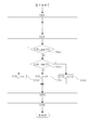
- FIG. 2 is a flowchart showing the first embodiment of EGR correction control
- FIG. 3 shows the configuration of the EGR merging unit 13. It is a block diagram.
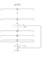
- FIG. 4 is a flowchart showing the second embodiment of EGR correction control
- FIG. 5 is a flowchart showing the third embodiment of EGR correction control
- FIG. 6 is a flowchart showing the fourth embodiment of EGR correction control.
- FIG. 7 is a flowchart showing the fifth embodiment of EGR correction control.
- Engine 100 is an industrial in-line four-cylinder diesel engine.
- the engine 100 includes an engine main body 40 and an ECU 60.
- the engine body 40 includes a cylinder block and a cylinder head, an intake path 10, an exhaust path 20, and an EGR path 30.
- the intake path 10 is a path for inhaling outside air.
- an air cleaner 11 In the intake path 10, an air cleaner 11, an intake flow sensor 63, and an EGR merging portion 13 are provided from the outside air side toward the intake manifold 15 connected to the cylinder head.
- the exhaust path 20 is a path for discharging exhaust gas.
- the exhaust path 20 is provided with an EGR branch portion 23 and a muffler 21 from the exhaust manifold 25 connected to the cylinder head toward the outside air side.
- the EGR path 30 is a path for circulating a part of the exhaust gas flowing through the exhaust path 20 to the intake path 10, and the EGR branch part 23 provided in the middle part of the exhaust path 20 and the middle part of the intake path 10. It is formed by connecting the EGR junction 13 provided in the.
- an EGR cooler 31 In the EGR path 30, an EGR cooler 31, an EGR adjustment valve 35, a differential pressure sensor 62, and a temperature sensor 61 are provided from the EGR branch portion 23 toward the EGR junction portion 13.
- the ECU 60 includes a controller 50 that is an arithmetic device and a storage device 55.
- the ECU 60 includes a temperature sensor 61 and a differential pressure sensor 62 provided in the EGR path 30, an intake flow rate sensor 63 provided in the intake path 10, an engine speed sensor 65 and an engine load sensor 66 provided in the engine body 40. And a control signal is created based on the electric signal from these.
- the ECU 60 stores an EGR opening degree map and an EGR rate map in order to operate the engine body 40 in response to an operator's request and adjust the flow rate of the exhaust gas recirculated to the intake passage 10 to an appropriate value. ing.
- the optimum control factor found in advance by a test is stored in order to adjust the flow rate of the exhaust gas recirculated to the intake passage 10 according to the operating state of the engine body 40. Is. Thereby, the ECU 60 can control the flow rate of the exhaust gas recirculated to the intake passage 10 by calling a control factor from each map and creating a control signal.
- the temperature sensor 61 has a function of detecting the temperature T of the exhaust gas flowing through the EGR path 30 and transmitting it to the ECU 60.
- the intake flow rate sensor 63 has a function of detecting the intake flow rate Ga upstream of the EGR merging portion 13, which is a connection portion of the intake path 10 with the EGR path 30, and transmitting it to the ECU 60.
- the engine speed sensor 65 has a function of detecting the engine speed Ne and transmitting it to the ECU 60.
- the engine load sensor 66 has a function of detecting the load L of the engine body 40 and transmitting it to the ECU 60.
- the engine load sensor 66 is a sensor provided in a fuel metering mechanism that adjusts the amount of fuel supplied to the combustion chamber, but the load L is calculated by calculating the amount of fuel supplied to the combustion chamber. It is good also as a structure which grasps
- Emodiment 1 A first embodiment of EGR correction control will be described with reference to FIG.
- the controller 50 performs EGR correction control by executing the following steps.
- S100 the engine speed Ne, the load L, the temperature T, the pressure difference dP, and the intake air flow rate Ga are detected.
- the relationship between the engine speed Ne and the load L and the EGR opening is stored in advance using the engine speed Ne detected by the engine speed sensor 65 and the load L detected by the engine load sensor 66.
- a reference EGR opening degree EGR_s is calculated by calling an appropriate control factor from the EGR opening degree map D (Ne, L).
- the EGR opening degree map D (Ne, L) is a two-dimensional map stored in advance in the storage device 55 of the ECU 60.
- a simple moving average for the 10 most recently detected values is calculated for the engine speed Ne, load L, temperature T, pressure difference dP, and intake air flow rate Ga detected at predetermined intervals.
- the index EGR rate EGR_t is calculated based on the temperature T, the pressure difference dP, and the intake air flow rate Ga.
- the flow rate of the air-fuel mixture is a value obtained by adding the flow rate Ga of the intake air and the flow rate Ge of the exhaust gas flowing through the EGR path 30 (Ga + Ge).
- the EGR rate which is the ratio of the exhaust gas flow rate Ge to the air-fuel mixture flow rate (Ga + Ge), is expressed by the following formula 1.
- the engine speed Ne detected by the engine speed sensor 65 and the load L detected by the engine load sensor 66 are used, and the relationship between the engine speed Ne and the load L and the EGR rate is stored in advance.
- a reference EGR rate EGR_std is calculated by calling an appropriate control factor from the rate map R (Ne, L).
- the EGR rate map R (Ne, L) is a two-dimensional map stored in advance in the storage device 55 of the ECU 60.
- a deviation EGR_gap which is a deviation between the index EGR rate EGR_t and the reference EGR rate EGR_std, is calculated.
- the corrected EGR value EGR_re is calculated so that the deviation EGR_gap becomes zero.
- the reference EGR opening degree EGR_s is corrected based on the corrected EGR value EGR_re. Thereby, the corrected EGR opening degree EGR_s_re is calculated.
- the corrected EGR opening degree EGR_s_re is transmitted to the EGR adjustment valve 35 as a control signal.
- the index EGR rate EGR_t is calculated from the flow rate Ga of the intake air flowing through the intake path 10, the temperature T of the exhaust gas flowing through the EGR path 30, and the pressure difference dP between the upstream side and the downstream side of the EGR adjustment valve 35. Since the EGR adjustment valve 35 is feedback-controlled, the flow rate Ge of the exhaust gas recirculated to the intake passage 10 can be adjusted to an appropriate value. That is, even when the operating state of the engine main body 40 changes greatly, it is possible to realize appropriate EGR correction control.
- S623 it is determined whether or not the count number n exceeds the predetermined value n1, and when the count number n exceeds the predetermined value n1, the process proceeds to S700. Since S700 to S900 are the same as those in the first embodiment, the description thereof is omitted.
- the controller 50 calculates the corrected EGR value EGR_re only when the number of times that the deviation EGR_gap is larger than the predetermined value r1 exceeds the predetermined value n1.
- frequent control of the EGR adjustment valve 35 with respect to the minute deviation EGR_gap can be avoided, and the flow rate Ge of the exhaust gas recirculated to the intake path 10 can be stabilized.
- Embodiment 3 of EGR correction control will be described with reference to FIG.
- S100 to S600 are the same as those in the first embodiment, description thereof is omitted.
- S630 an integrated value EGR_gap_sum of the deviation EGR_gap calculated in S600 is calculated for each predetermined period.
- S631 it is determined whether or not the integrated value EGR_gap_sum calculated in S630 is greater than a predetermined value r2.
- the integrated value EGR_gap_sum is larger than the predetermined value r2, the process proceeds to S700, and if it is smaller than the predetermined value r2, the EGR correction control is ended. Since S700 to S900 are the same as those in the first embodiment, the description thereof is omitted.
- the controller 50 calculates the corrected EGR value EGR_re only when the integrated value EGR_gap_sum becomes larger than the predetermined value r2.
- frequent control of the EGR adjustment valve 35 with respect to the minute deviation EGR_gap can be avoided, and the flow rate Ge of the exhaust gas recirculated to the intake path 10 can be stabilized.
- S100 to S600 are the same as those in the first embodiment, and thus the description thereof is omitted.
- S640 it is determined whether or not the deviation EGR_gap calculated in S600 is greater than zero.
- the predetermined value d is given as the corrected EGR value EGR_re in S740, and when the deviation EGR_gap is smaller than 0, the process proceeds to S641.
- S641 it is determined whether or not the deviation EGR_gap is smaller than zero.
- the controller 50 can calculate an appropriate correction EGR opening degree EGR_s_re even when the excessive correction EGR value EGR_re is calculated, and the flow rate Ge of the exhaust gas recirculated to the intake path 10 Can be stabilized.
- Embodiment 5 of EGR correction control will be described with reference to FIG.
- S100 to S600 are the same as those in the first embodiment, the description thereof is omitted.
- S650 it is determined whether or not the time t from when the corrected EGR opening degree EGR_s_re was transmitted to the EGR adjustment valve 35 as a control signal most recently exceeded a predetermined value t1. If the time t exceeds the predetermined value t1, the process proceeds to S700. If the time t does not exceed the predetermined value t1, the EGR correction control is terminated. Since S700 to S900 are the same as those in the first embodiment, the description thereof is omitted.
- the controller 50 calculates the corrected EGR value EGR_re only when the time t from when the corrected EGR opening degree EGR_s_re was most recently transmitted to the EGR adjustment valve 35 exceeds the predetermined value t1.
- frequent control of the EGR adjustment valve 35 with respect to the minute deviation EGR_gap can be avoided, and the flow rate Ge of the exhaust gas recirculated to the intake path 10 can be stabilized.
- the predetermined minimum of the EGR adjustment valve 35 is set.
- the opening is transmitted to the EGR adjustment valve 35 as the corrected EGR opening EGR_s_re.
- the calculated EGR opening degree EGR_s_re is used to calculate the control factor of the EGR opening degree map D (Ne, L) described above, and to update to this control factor. Is done. As a result, even when the flow rate Ge of the exhaust gas recirculated to the intake passage 10 changes due to aging deterioration of the engine body 40 or the like, optimal EGR correction control is always realized.
- the present invention can be used for an engine equipped with an EGR device.
Landscapes
- Engineering & Computer Science (AREA)
- Chemical & Material Sciences (AREA)
- Combustion & Propulsion (AREA)
- Mechanical Engineering (AREA)
- General Engineering & Computer Science (AREA)
- Physics & Mathematics (AREA)
- Fluid Mechanics (AREA)
- Analytical Chemistry (AREA)
- Exhaust-Gas Circulating Devices (AREA)
Abstract
エンジン回転数Neおよび負荷LとEGR開度との関係が記憶されたEGR開度マップD(Ne、L)に基づいて基準EGR開度EGR_sを算出し、エンジン回転数Neおよび負荷LとEGR率との関係が記憶されたEGR率マップR(Ne、L)に基づいて基準EGR率EGR_stdを算出し、吸気の流量Gaを検出する吸気流量センサ63やEGR調整弁35の上流側と下流側の圧力差を検出する差圧センサ62、EGR経路30を流れる排気ガスの温度Tを検出する温度センサ61による検出結果に基づいて指標EGR率EGR_tを算出し、基準EGR率EGR_stdおよび指標EGR率EGR_tに基づいて補正EGR値EGR_reを算出し、補正EGR値EGR_reに基づいて基準EGR開度EGR_sを補正した値である補正EGR開度EGR_s_reを算出して制御信号としてEGR調整弁35に送信する。
Description
本発明は、EGR装置を備えるエンジンの制御技術に関する。
従来、EGR(Exhaust Gas Recirculation)装置を備えるエンジンは公知である。EGR装置は、排気経路を流れる排気ガスの一部を吸気経路へ環流させるために排気経路と吸気経路とを接続するEGR経路と、該EGR経路を流れる排気ガスの流量を調整するためのEGR調整弁とで構成されている。
このようなEGR装置の制御手法として、λ制御手法が公知となっている。λ制御手法は、エンジンの体積効率を考慮し、エンジンの燃焼室に吸入される吸気量や燃焼室に供給される燃料量から空気過剰率λ(理論上必要とされる吸気量に対する実吸気量の比)を算出し、この空気過剰率λに基づいてEGR調整弁の開度を調整する制御手法である。特許文献1は、排気ガスの圧力変化に応じてエンジンの体積効率を補正するλ制御手法を開示している。
特開2008-38709号公報
しかし、特許文献1に開示されたλ制御手法は、エンジンの運転状態がほぼ定常的である自動車用エンジンに用いることを想定しており、エンジンの運転状態が大きく変化する産業用エンジンに用いることは想定されていない。つまり、特許文献1に開示されたλ制御手法は、産業用エンジンに用いることができなかった。
本発明の解決しようとする課題を解決するための手段を説明する。
本発明の第一の態様は、外気を吸入するための吸気経路の中途部と排気ガスを排出するための排気経路の中途部とを接続し、前記排気経路を流れる排気ガスの一部を前記吸気経路へ還流させるためのEGR経路が形成されたエンジンであって、前記EGR経路に配置され、該EGR経路を流れる排気ガスの流量を調整するEGR調整弁と、前記吸気経路の前記EGR経路の接続部よりも上流側に配置され、該吸気経路を流れる吸気の流量を検出する吸気流量センサと、前記EGR経路に配置され、前記EGR調整弁の上流側と下流側の圧力差を検出する差圧センサと、前記EGR経路に配置され、該EGR経路を流れる排気ガスの温度を検出する温度センサと、制御信号を送信することにより前記EGR調整弁の開度を制御する制御装置と、を具備し、前記制御装置は、エンジン回転数および負荷とEGR開度との関係が予め記憶されたEGR開度マップに基づいて基準EGR開度を算出し、エンジン回転数および負荷とEGR率との関係が予め記憶されたEGR率マップに基づいて基準EGR率を算出し、前記吸気流量センサや前記差圧センサ、前記温度センサによる検出結果に基づいて指標EGR率を算出し、前記基準EGR率および前記指標EGR率に基づいて補正EGR値を算出し、前記補正EGR値に基づいて前記基準EGR開度を補正した値である補正EGR開度を算出し、前記補正EGR開度を制御信号として前記EGR調整弁に送信するものである。
本発明の第二の態様は、第一の態様のエンジンにおいて、前記制御装置は、所定周期毎に前記補正EGR開度を算出するものである。
本発明の第三の態様は、第一の態様のエンジンにおいて、前記制御装置は、所定周期毎に前記基準EGR率と前記指標EGR率との偏差を算出するとともに該偏差が所定差以上となった回数をカウントし、該カウントが予め定められた回数以上となった場合に前記補正EGR開度を算出するものである。
本発明の第四の態様は、第一の態様のエンジンにおいて、前記制御装置は、所定周期毎に前記基準EGR率と前記指標EGR率との偏差を算出するとともに該偏差の積算値を算出し、該積算値が予め定められた数値以上となった場合に前記補正EGR開度を算出するものである。
本発明の第五の態様は、第一の態様のエンジンにおいて、前記制御装置は、前記基準EGR率と前記指標EGR率との偏差が正の値であるか負の値であるかに応じて前記補正EGR値の代わりとなる所定の絶対値を用いて前記補正EGR開度を算出するものである。
本発明の第六の態様は、第一の態様のエンジンにおいて、前記制御装置は、前記エンジンのエンジン回転数として所定周期毎の移動平均値を算出し、前記エンジンの負荷として所定周期毎の移動平均値を算出し、前記EGR経路を流れる排気ガスの温度として所定周期毎の移動平均値を算出し、前記EGR調整弁の上流側と下流側の圧力差として所定周期毎の移動平均値を算出し、算出された移動平均値を用いて前記補正EGR開度を算出するものである。
本発明の第七の態様は、第一の態様のエンジンにおいて、前記制御装置は、算出された前記補正EGR開度が前記EGR調整弁の所定の最小開度よりも小さくなる場合には、前記EGR調整弁の所定の最小開度を前記補正EGR開度として前記EGR調整弁へ送信するものである。
本発明の効果として、以下に示すような効果を奏する。
本発明の第一の態様においては、各センサによって検出された吸気の流量と、EGR経路を流れる排気ガスの温度と、EGR調整弁の上流側と下流側の圧力差とから指標EGR率を算出してEGR調整弁をフィードバック制御するため、吸気経路に還流させる排気ガスの流量を適正な値に調整できる。つまり、エンジンの運転状態が大きく変化する場合であっても適正なEGR補正制御を実現することができる。
本発明の第二の態様においては、所定周期毎に補正EGR開度を算出することによって吸気経路に還流させる排気ガスの流量を安定させることが可能となる。
本発明の第三の態様においては、微小な偏差では補正EGR開度を算出しないために微小な偏差に対してEGR調整弁を頻繁に制御することが回避できる。これにより、吸気経路に還流させる排気ガスの流量を安定させることが可能となる。
本発明の第四の態様においては、微小な偏差では補正EGR開度を算出しないために微小な偏差に対してEGR調整弁を頻繁に制御することが回避できる。これにより、吸気経路に還流させる排気ガスの流量を安定させることが可能となる。
本発明の第五の態様においては、過大な補正EGR値が算出された場合であっても、適度な補正EGR開度を算出することで吸気経路に還流させる排気ガスの流量を安定させることが可能となる。
本発明の第六の態様においては、エンジンの運転状態が大きく変化しても適正な前記補正EGR開度を算出できる。これにより、吸気経路に還流させる排気ガスの流量を安定させることが可能となる。
本発明の第七の態様においては、エンジンの運転状態にかかわらず吸気経路に還流させる排気ガスの最小流量を確保することが可能となる。
10 吸気経路
20 排気経路
30 EGR経路
35 EGR調整弁
50 コントローラ
55 記憶装置
60 ECU
61 温度センサ
62 差圧センサ
63 吸気流量センサ
100 エンジン
EGR_s 基準EGR開度
EGR_re 補正EGR値
EGR_s_re 補正EGR開度
EGR_std 基準EGR率
EGR_t 指標EGR率
EGR_gap 偏差
EGR_gap_sum 積算値
20 排気経路
30 EGR経路
35 EGR調整弁
50 コントローラ
55 記憶装置
60 ECU
61 温度センサ
62 差圧センサ
63 吸気流量センサ
100 エンジン
EGR_s 基準EGR開度
EGR_re 補正EGR値
EGR_s_re 補正EGR開度
EGR_std 基準EGR率
EGR_t 指標EGR率
EGR_gap 偏差
EGR_gap_sum 積算値
次に、発明の実施の形態について説明する。
図1は本発明の実施形態に係るエンジン100の全体的な構成を示す構成図、図2は同じくEGR補正制御の実施形態1を示すフロー図、図3は同じくEGR合流部13の構成を示す構成図である。
図4は同じくEGR補正制御の実施形態2を示すフロー図、図5は同じくEGR補正制御の実施形態3を示すフロー図、図6は同じくEGR補正制御の実施形態4を示すフロー図である。
図7は同じくEGR補正制御の実施形態5を示すフロー図である。
図4は同じくEGR補正制御の実施形態2を示すフロー図、図5は同じくEGR補正制御の実施形態3を示すフロー図、図6は同じくEGR補正制御の実施形態4を示すフロー図である。
図7は同じくEGR補正制御の実施形態5を示すフロー図である。
図1を用いて、本発明の実施形態であるエンジン100の構成について説明する。エンジン100は、産業用の直列4気筒ディーゼルエンジンである。また、エンジン100は、エンジン本体40と、ECU60と、を備えている。
エンジン本体40は、シリンダブロックおよびシリンダヘッドと、吸気経路10と、排気経路20と、EGR経路30と、を備えている。
エンジン本体40は、シリンダブロックおよびシリンダヘッドと、吸気経路10と、排気経路20と、EGR経路30と、を備えている。
吸気経路10は、外気を吸入するための経路である。吸気経路10には、外気側からシリンダヘッドに接続された吸気マニホールド15に向かって、エアクリーナ11、吸気流量センサ63、EGR合流部13が設けられている。
排気経路20は、排気ガスを排出するための経路である。排気経路20には、シリンダヘッドに接続された排気マニホールド25から外気側に向かって、EGR分岐部23、およびマフラー21が設けられている。
EGR経路30は、排気経路20を流れる排気ガスの一部を吸気経路10に環流させるための経路であって、排気経路20の中途部に設けられたEGR分岐部23と吸気経路10の中途部に設けられたEGR合流部13とを接続して形成されている。また、EGR経路30には、EGR分岐部23からEGR合流部13に向かって、EGRクーラ31、EGR調整弁35、差圧センサ62、温度センサ61が設けられている。
ECU60は、演算装置であるコントローラ50と、記憶装置55と、を備えている。
ECU60は、EGR経路30に設けられた温度センサ61や差圧センサ62、吸気経路10に設けられた吸気流量センサ63、そして、エンジン本体40に設けられたエンジン回転数センサ65ならびにエンジン負荷センサ66と電気的に接続されて、これらからの電気信号に基づいて制御信号を作成するものとされる。
ECU60は、EGR経路30に設けられた温度センサ61や差圧センサ62、吸気経路10に設けられた吸気流量センサ63、そして、エンジン本体40に設けられたエンジン回転数センサ65ならびにエンジン負荷センサ66と電気的に接続されて、これらからの電気信号に基づいて制御信号を作成するものとされる。
また、ECU60には、オペレータの要求に応じてエンジン本体40の運転を行うとともに吸気経路10に還流させる排気ガスの流量を適正な値に調整すべく、EGR開度マップ、EGR率マップが記憶されている。
EGR開度マップならびにEGR率マップは、エンジン本体40の運転状態に応じて吸気経路10に還流させる排気ガスの流量を調整するために、予め試験によって見出された最適な制御因子が記憶されたものである。これにより、ECU60は、各マップから制御因子を呼出して制御信号を作成することで吸気経路10に還流させる排気ガスの流量を制御可能としている。
温度センサ61は、EGR経路30を流れる排気ガスの温度Tを検出し、ECU60に送信する機能を有する。差圧センサ62は、EGR調整弁35の上流側と下流側の圧力差dP(dP=P1―P2)を検出し、ECU60に送信する機能を有する。なお、EGR調整弁35の上流側と下流側にそれぞれ圧力センサを設けて、検出された圧力値から圧力差を算出する構成としても良い。吸気流量センサ63は、吸気経路10のEGR経路30との接続部分であるEGR合流部13よりも上流側で吸気の流量Gaを検出し、ECU60に送信する機能を有する。
エンジン回転数センサ65は、エンジン回転数Neを検出し、ECU60に送信する機能を有する。エンジン負荷センサ66は、エンジン本体40の負荷Lを検出し、ECU60に送信する機能を有する。本実施形態において、エンジン負荷センサ66は、燃焼室に供給される燃料量を調節する燃料調量機構に設けられたセンサであるが、燃焼室に供給される燃料量を算出することによって負荷Lを把握する構成としても良い。
[実施形態1]
図2を用いて、EGR補正制御の実施形態1について説明する。コントローラ50は、以下の各ステップを実行することでEGR補正制御を行う。
S100において、エンジン回転数Neと、負荷Lと、温度Tと、圧力差dPと、吸気の流量Gaと、が検出される。
図2を用いて、EGR補正制御の実施形態1について説明する。コントローラ50は、以下の各ステップを実行することでEGR補正制御を行う。
S100において、エンジン回転数Neと、負荷Lと、温度Tと、圧力差dPと、吸気の流量Gaと、が検出される。
S200において、エンジン回転数センサ65によって検出されたエンジン回転数Neとエンジン負荷センサ66によって検出された負荷Lとを用い、エンジン回転数Neおよび負荷LとEGR開度との関係が予め記憶されたEGR開度マップD(Ne、L)から適当な制御因子を呼出することによって基準EGR開度EGR_sが算出される。なお、EGR開度マップD(Ne、L)は、ECU60の記憶装置55に予め記憶されている2次元マップである。
S300において、所定周期毎に検出されたエンジン回転数Neと、負荷Lと、温度Tと、圧力差dPと、吸気の流量Gaとについて、直近に検出された10回分の単純移動平均が算出される。以下ではエンジン回転数Neと、負荷Lと、温度Tと、圧力差dPと、吸気の流量Gaとについては単純移動平均の値であるとする。
これは、エンジン本体40の運転状態が大きく変化した場合であっても最適なEGR補正制御を実現させるためである。
これは、エンジン本体40の運転状態が大きく変化した場合であっても最適なEGR補正制御を実現させるためである。
S400において、温度Tと、圧力差dPと、吸気の流量Gaとに基づいて指標EGR率EGR_tが算出される。
図3を用いて、指標EGR率EGR_tの算出方法について詳細に説明する。EGR合流部13において、吸気経路10を流れる吸気とEGR経路30を流れる排気ガスとが合流して混合気が生成される。この混合気の流量は、吸気の流量GaとEGR経路30を流れる排気ガスの流量Geとを加算した値(Ga+Ge)となる。そして、混合気の流量(Ga+Ge)における排気ガスの流量Geの割合であるEGR率は、下記の数1で表される。

また、EGR経路30において、EGR調整弁35の上流側(速度v1、圧力P1、温度T)と下流側(速度v2、圧力P2、温度T)のエネルギーはエネルギー保存の法則により等しいために、下記のベルヌーイの式である数2によって表される。

数2について、z1=0、z2=0、v1=0としたとき、下記の数3が得られる。

そして、比重量を温度考慮して定数部をまとめてCとすると、下記の数4が得られる。

更にEGR調整弁35の開度面積Aとすると、EGR経路30を流れる排気ガスの流量Geが下記の数5として表される。

このようにして得られたEGR経路30を流れる排気ガスの流量Geと、吸気経路10を流れる吸気の流量GaとをEGR率を算出する式である数1に代入することで指標EGR率EGR_tが得られる。
S500において、エンジン回転数センサ65によって検出されたエンジン回転数Neとエンジン負荷センサ66によって検出された負荷Lとを用い、エンジン回転数Neおよび負荷LとEGR率との関係が予め記憶されたEGR率マップR(Ne、L)から適当な制御因子を呼出することによって基準EGR率EGR_stdが算出される。なお、EGR率マップR(Ne、L)は、ECU60の記憶装置55に予め記憶されている2次元マップである。
S600において、指標EGR率EGR_tと基準EGR率EGR_stdとの偏差である偏差EGR_gapが算出される。
S700において、偏差EGR_gapが0となるように補正EGR値EGR_reが算出される。
S800において、補正EGR値EGR_reに基づいて基準EGR開度EGR_sを補正する。これによって、補正EGR開度EGR_s_reが算出される。
S900において、補正EGR開度EGR_s_reが制御信号としてEGR調整弁35へ送信される。
S700において、偏差EGR_gapが0となるように補正EGR値EGR_reが算出される。
S800において、補正EGR値EGR_reに基づいて基準EGR開度EGR_sを補正する。これによって、補正EGR開度EGR_s_reが算出される。
S900において、補正EGR開度EGR_s_reが制御信号としてEGR調整弁35へ送信される。
このようにして、吸気経路10を流れる吸気の流量Gaと、EGR経路30を流れる排気ガスの温度Tと、EGR調整弁35の上流側と下流側の圧力差dPとから指標EGR率EGR_tを算出してEGR調整弁35をフィードバック制御するため、吸気経路10に還流させる排気ガスの流量Geを適正な値に調整できる。つまり、エンジン本体40の運転状態が大きく変化する場合であっても適正なEGR補正制御を実現することが可能となる。
[実施形態2]
図4を用いて、EGR補正制御の実施形態2について説明する。実施形態2におけるS100~S600は実施形態1と同様であるため、説明を省略する。
S620において、所定周期毎にS600で算出された偏差EGR_gapが、所定値r1より大きいかどうかが都度判定される。ここで、偏差EGR_gapが所定値r1より大きい場合は、S621においてカウント数nが+1増加され、所定値r1より小さい場合は、S622においてカウント数nはそのままとされる。
S623において、カウント数nが所定値n1を超えたかどうかが判定され、カウント数nが所定値n1を超えた場合にS700に移行される。なお、S700~S900は実施形態1と同様であるため、説明を省略する。
図4を用いて、EGR補正制御の実施形態2について説明する。実施形態2におけるS100~S600は実施形態1と同様であるため、説明を省略する。
S620において、所定周期毎にS600で算出された偏差EGR_gapが、所定値r1より大きいかどうかが都度判定される。ここで、偏差EGR_gapが所定値r1より大きい場合は、S621においてカウント数nが+1増加され、所定値r1より小さい場合は、S622においてカウント数nはそのままとされる。
S623において、カウント数nが所定値n1を超えたかどうかが判定され、カウント数nが所定値n1を超えた場合にS700に移行される。なお、S700~S900は実施形態1と同様であるため、説明を省略する。
このようにして、コントローラ50は、偏差EGR_gapが所定値r1より大きくなった回数が所定値n1を超えた場合にのみ、補正EGR値EGR_reを算出する。これにより、微小な偏差EGR_gapに対してEGR調整弁35を頻繁に制御することが回避でき、吸気経路10に還流させる排気ガスの流量Geを安定させることが可能となる。
[実施形態3]
図5を用いて、EGR補正制御の実施形態3について説明する。実施形態3において、S100~S600は実施形態1と同様であるため、説明を省略する。
S630において、所定周期毎にS600で算出された偏差EGR_gapの積算値EGR_gap_sumを算出する。
そして、S631において、S630にて算出された積算値EGR_gap_sumが所定値r2より大きいかどうかが判定される。ここで、積算値EGR_gap_sumが所定値r2より大きい場合は、S700へ移行され、所定値r2より小さい場合は、EGR補正制御が終了される。なお、S700~S900は実施形態1と同様であるため、説明を省略する。
図5を用いて、EGR補正制御の実施形態3について説明する。実施形態3において、S100~S600は実施形態1と同様であるため、説明を省略する。
S630において、所定周期毎にS600で算出された偏差EGR_gapの積算値EGR_gap_sumを算出する。
そして、S631において、S630にて算出された積算値EGR_gap_sumが所定値r2より大きいかどうかが判定される。ここで、積算値EGR_gap_sumが所定値r2より大きい場合は、S700へ移行され、所定値r2より小さい場合は、EGR補正制御が終了される。なお、S700~S900は実施形態1と同様であるため、説明を省略する。
このようにして、コントローラ50は、積算値EGR_gap_sumが所定値r2より大きくなった場合にのみ、補正EGR値EGR_reを算出する。これにより、微小な偏差EGR_gapに対してEGR調整弁35を頻繁に制御することが回避でき、吸気経路10に還流させる排気ガスの流量Geを安定させることが可能となる。
[実施形態4]
図6を用いて、EGR補正制御の実施形態4について説明する。実施形態4において、S100~S600は実施形態1と同様であるため、説明を省略する。
S640において、S600で算出された偏差EGR_gapが0より大きいかどうかが判定される。ここで、偏差EGR_gapが0より大きい場合は、S740において補正EGR値EGR_reとして所定値dが与えられ、偏差EGR_gapが0より小さい場合は、S641へ移行される。
S641において、偏差EGR_gapが0より小さいかどうかが判定される。ここで、偏差EGR_gapが0より小さければ、S742において補正EGR値EGR_reとして所定値-dが与えられる。
また、偏差EGR_gapが0である場合は、S741において補正EGR値EGR_reとして0が与えられる。なお、S800ならびにS900は実施形態1と同様であるため、説明を省略する。
図6を用いて、EGR補正制御の実施形態4について説明する。実施形態4において、S100~S600は実施形態1と同様であるため、説明を省略する。
S640において、S600で算出された偏差EGR_gapが0より大きいかどうかが判定される。ここで、偏差EGR_gapが0より大きい場合は、S740において補正EGR値EGR_reとして所定値dが与えられ、偏差EGR_gapが0より小さい場合は、S641へ移行される。
S641において、偏差EGR_gapが0より小さいかどうかが判定される。ここで、偏差EGR_gapが0より小さければ、S742において補正EGR値EGR_reとして所定値-dが与えられる。
また、偏差EGR_gapが0である場合は、S741において補正EGR値EGR_reとして0が与えられる。なお、S800ならびにS900は実施形態1と同様であるため、説明を省略する。
このようにして、コントローラ50は、過大な補正EGR値EGR_reが算出された場合であっても、適度な補正EGR開度EGR_s_reを算出することができ、吸気経路10に還流させる排気ガスの流量Geを安定させることが可能となる。
[実施形態5]
図7を用いて、EGR補正制御の実施形態5について説明する。実施形態5において、S100~S600は実施形態1と同様であるため、説明を省略する。
S650において、直近に補正EGR開度EGR_s_reを制御信号としてEGR調整弁35に送信したときからの時間tが所定値t1を超えたかどうかが判定される。ここで、時間tが所定値t1を越えた場合は、S700へ移行され、時間tが所定値t1を越えていない場合は、EGR補正制御は終了される。なお、S700~S900は実施形態1と同様であるため、説明を省略する。
図7を用いて、EGR補正制御の実施形態5について説明する。実施形態5において、S100~S600は実施形態1と同様であるため、説明を省略する。
S650において、直近に補正EGR開度EGR_s_reを制御信号としてEGR調整弁35に送信したときからの時間tが所定値t1を超えたかどうかが判定される。ここで、時間tが所定値t1を越えた場合は、S700へ移行され、時間tが所定値t1を越えていない場合は、EGR補正制御は終了される。なお、S700~S900は実施形態1と同様であるため、説明を省略する。
このようにして、コントローラ50は、直近に補正EGR開度EGR_s_reをEGR調整弁35へ送信したときからの時間tが所定値t1を越えた場合にのみ、補正EGR値EGR_reを算出する。これにより、微小な偏差EGR_gapに対してEGR調整弁35を頻繁に制御することが回避でき、吸気経路10に還流させる排気ガスの流量Geを安定させることが可能となる。
また、本発明に係るエンジン100においては、算出された補正EGR開度EGR_s_reがEGR調整弁35の所定の最小開度よりも小さくなった場合であっても、該EGR調整弁35の所定の最小開度を補正EGR開度EGR_s_reとしてEGR調整弁35へ送信するものとされる。これにより、エンジン本体40の運転状態にかかわらず吸気経路10に還流させる排気ガスの最小流量を確保することが可能となる。
更に、本発明に係るエンジン100においては、算出された補正EGR開度EGR_s_reを用いることで前述したEGR開度マップD(Ne、L)の制御因子を逆算し、この制御因子に更新するものとされる。これにより、エンジン本体40の経年劣化等によって吸気経路10に還流させる排気ガスの流量Geが変化した場合であっても、常に最適なEGR補正制御が実現される。
本発明は、EGR装置を備えるエンジンに利用可能である。
Claims (7)
- 外気を吸入するための吸気経路の中途部と排気ガスを排出するための排気経路の中途部とを接続し、前記排気経路を流れる排気ガスの一部を前記吸気経路へ還流させるためのEGR経路が形成されたエンジンであって、
前記EGR経路に配置され、該EGR経路を流れる排気ガスの流量を調整するEGR調整弁と、
前記吸気経路の前記EGR経路の接続部よりも上流側に配置され、該吸気経路を流れる吸気の流量を検出する吸気流量センサと、
前記EGR経路に配置され、前記EGR調整弁の上流側と下流側の圧力差を検出する差圧センサと、
前記EGR経路に配置され、該EGR経路を流れる排気ガスの温度を検出する温度センサと、
制御信号を送信することにより前記EGR調整弁の開度を制御する制御装置と、
を具備し、
前記制御装置は、
エンジン回転数および負荷とEGR開度との関係が予め記憶されたEGR開度マップに基づいて基準EGR開度を算出し、
エンジン回転数および負荷とEGR率との関係が予め記憶されたEGR率マップに基づいて基準EGR率を算出し、
前記吸気流量センサや前記差圧センサ、前記温度センサによる検出結果に基づいて指標EGR率を算出し、
前記基準EGR率および前記指標EGR率に基づいて補正EGR値を算出し、
前記補正EGR値に基づいて前記基準EGR開度を補正した値である補正EGR開度を算出し、
前記補正EGR開度を制御信号として前記EGR調整弁に送信するエンジン。 - 前記制御装置は、所定周期毎に前記補正EGR開度を算出する請求項1に記載のエンジン。
- 前記制御装置は、所定周期毎に前記基準EGR率と前記指標EGR率との偏差を算出するとともに該偏差が所定差以上となった回数をカウントし、該カウントが予め定められた回数以上となった場合に前記補正EGR開度を算出する請求項1に記載のエンジン。
- 前記制御装置は、所定周期毎に前記基準EGR率と前記指標EGR率との偏差を算出するとともに該偏差の積算値を算出し、該積算値が予め定められた数値以上となった場合に前記補正EGR開度を算出する請求項1に記載のエンジン。
- 前記制御装置は、前記基準EGR率と前記指標EGR率との偏差が正の値であるか負の値であるかに応じて前記補正EGR値の代わりとなる所定の絶対値を用いて前記補正EGR開度を算出する請求項1に記載のエンジン。
- 前記制御装置は、前記エンジンのエンジン回転数として所定周期毎の移動平均値を算出し、
前記エンジンの負荷として所定周期毎の移動平均値を算出し、
前記EGR経路を流れる排気ガスの温度として所定周期毎の移動平均値を算出し、
前記EGR調整弁の上流側と下流側の圧力差として所定周期毎の移動平均値を算出し、
算出された移動平均値を用いて前記補正EGR開度を算出する請求項1に記載のエンジン。 - 前記制御装置は、算出された前記補正EGR開度が前記EGR調整弁の所定の最小開度よりも小さくなる場合には、前記EGR調整弁の所定の最小開度を前記補正EGR開度として前記EGR調整弁へ送信する請求項1に記載のエンジン。
Applications Claiming Priority (2)
| Application Number | Priority Date | Filing Date | Title |
|---|---|---|---|
| JP2008-251086 | 2008-09-29 | ||
| JP2008251086A JP2010084519A (ja) | 2008-09-29 | 2008-09-29 | エンジン |
Publications (1)
| Publication Number | Publication Date |
|---|---|
| WO2010035554A1 true WO2010035554A1 (ja) | 2010-04-01 |
Family
ID=42059562
Family Applications (1)
| Application Number | Title | Priority Date | Filing Date |
|---|---|---|---|
| PCT/JP2009/060670 Ceased WO2010035554A1 (ja) | 2008-09-29 | 2009-06-11 | エンジン |
Country Status (2)
| Country | Link |
|---|---|
| JP (1) | JP2010084519A (ja) |
| WO (1) | WO2010035554A1 (ja) |
Cited By (7)
| Publication number | Priority date | Publication date | Assignee | Title |
|---|---|---|---|---|
| GB2484297A (en) * | 2010-10-05 | 2012-04-11 | Gm Global Tech Operations Inc | A combustion engine evaluation unit comprising fault detection system for engine using EGR |
| WO2014080523A1 (ja) * | 2012-11-26 | 2014-05-30 | トヨタ自動車株式会社 | 内燃機関の制御装置 |
| EP2687710A4 (en) * | 2011-03-18 | 2014-09-03 | Yanmar Co Ltd | METHOD FOR DETERMINING THE IMPORTANCE OF CORRECTING OPENING DEGREE OF EGR VALVE, METHOD OF CONTROLLING EGR VALVE OPENING DEGREE AND MOTOR |
| CN106677911A (zh) * | 2015-11-05 | 2017-05-17 | 福特环球技术公司 | 用于排气再循环系统的开环和闭环控制的方法和系统 |
| GB2549286A (en) * | 2016-04-11 | 2017-10-18 | Perkins Engines Co Ltd | EGR valve with integrated sensor |
| CN109555606A (zh) * | 2017-09-26 | 2019-04-02 | 株式会社斯巴鲁 | Egr控制装置 |
| CN112343723A (zh) * | 2019-08-06 | 2021-02-09 | 广州汽车集团股份有限公司 | Egr率的确定和egr阀的开度控制方法及相关装置 |
Families Citing this family (4)
| Publication number | Priority date | Publication date | Assignee | Title |
|---|---|---|---|---|
| KR101251516B1 (ko) * | 2010-12-06 | 2013-04-05 | 기아자동차주식회사 | 엔진 시스템 및 이의 신호처리 방법 |
| JP5761138B2 (ja) | 2012-08-24 | 2015-08-12 | 株式会社デンソー | Egr装置およびegr弁の特性検査装置 |
| CN109882301A (zh) * | 2019-03-26 | 2019-06-14 | 中国第一汽车股份有限公司 | 一种小排量汽油机废气再循环控制系统 |
| JP7480730B2 (ja) * | 2021-03-16 | 2024-05-10 | トヨタ自動車株式会社 | Egr弁の劣化度算出システム、内燃機関の制御装置、及び車両 |
Citations (3)
| Publication number | Priority date | Publication date | Assignee | Title |
|---|---|---|---|---|
| JPH11257053A (ja) * | 1998-03-13 | 1999-09-21 | Nissan Motor Co Ltd | ディーゼルエンジンの排気浄化装置 |
| JP2004150343A (ja) * | 2002-10-30 | 2004-05-27 | Komatsu Ltd | エンジンのegrシステムの制御方法 |
| JP2007255219A (ja) * | 2006-03-20 | 2007-10-04 | Toyota Motor Corp | 内燃機関のegr制御装置 |
-
2008
- 2008-09-29 JP JP2008251086A patent/JP2010084519A/ja active Pending
-
2009
- 2009-06-11 WO PCT/JP2009/060670 patent/WO2010035554A1/ja not_active Ceased
Patent Citations (3)
| Publication number | Priority date | Publication date | Assignee | Title |
|---|---|---|---|---|
| JPH11257053A (ja) * | 1998-03-13 | 1999-09-21 | Nissan Motor Co Ltd | ディーゼルエンジンの排気浄化装置 |
| JP2004150343A (ja) * | 2002-10-30 | 2004-05-27 | Komatsu Ltd | エンジンのegrシステムの制御方法 |
| JP2007255219A (ja) * | 2006-03-20 | 2007-10-04 | Toyota Motor Corp | 内燃機関のegr制御装置 |
Cited By (14)
| Publication number | Priority date | Publication date | Assignee | Title |
|---|---|---|---|---|
| GB2484297A (en) * | 2010-10-05 | 2012-04-11 | Gm Global Tech Operations Inc | A combustion engine evaluation unit comprising fault detection system for engine using EGR |
| EP2687710A4 (en) * | 2011-03-18 | 2014-09-03 | Yanmar Co Ltd | METHOD FOR DETERMINING THE IMPORTANCE OF CORRECTING OPENING DEGREE OF EGR VALVE, METHOD OF CONTROLLING EGR VALVE OPENING DEGREE AND MOTOR |
| US9243590B2 (en) | 2011-03-18 | 2016-01-26 | Yanmar Co., Ltd. | Method of determining correction amount of opening degree of EGR valve, method of controlling opening degree of EGR valve, and engine |
| WO2014080523A1 (ja) * | 2012-11-26 | 2014-05-30 | トヨタ自動車株式会社 | 内燃機関の制御装置 |
| JPWO2014080523A1 (ja) * | 2012-11-26 | 2017-01-05 | トヨタ自動車株式会社 | 内燃機関の制御装置 |
| CN106677911B (zh) * | 2015-11-05 | 2021-07-06 | 福特环球技术公司 | 用于排气再循环系统的开环和闭环控制的方法和系统 |
| CN106677911A (zh) * | 2015-11-05 | 2017-05-17 | 福特环球技术公司 | 用于排气再循环系统的开环和闭环控制的方法和系统 |
| GB2549286A (en) * | 2016-04-11 | 2017-10-18 | Perkins Engines Co Ltd | EGR valve with integrated sensor |
| GB2549286B (en) * | 2016-04-11 | 2019-07-24 | Perkins Engines Co Ltd | EGR valve with integrated sensor |
| US10774796B2 (en) | 2016-04-11 | 2020-09-15 | Perkins Engines Company Limited | EGR valve with integrated sensor |
| CN109555606A (zh) * | 2017-09-26 | 2019-04-02 | 株式会社斯巴鲁 | Egr控制装置 |
| CN109555606B (zh) * | 2017-09-26 | 2022-10-11 | 株式会社斯巴鲁 | Egr控制装置 |
| CN112343723A (zh) * | 2019-08-06 | 2021-02-09 | 广州汽车集团股份有限公司 | Egr率的确定和egr阀的开度控制方法及相关装置 |
| CN112343723B (zh) * | 2019-08-06 | 2022-12-30 | 广州汽车集团股份有限公司 | Egr率的确定和egr阀的开度控制方法及相关装置 |
Also Published As
| Publication number | Publication date |
|---|---|
| JP2010084519A (ja) | 2010-04-15 |
Similar Documents
| Publication | Publication Date | Title |
|---|---|---|
| CN101688483B (zh) | 内燃机的排气回流装置 | |
| JP2010084519A (ja) | エンジン | |
| JP4225322B2 (ja) | 内燃機関の排気還流装置 | |
| EP2198141A1 (en) | Exhaust-gas recirculation apparatus and exhaust-gas recirculation flow rate estimation method for internal combustion engines | |
| JP4715799B2 (ja) | 内燃機関の排気還流装置 | |
| US10309298B2 (en) | Control device of an engine | |
| JP6259246B2 (ja) | 内燃機関の制御装置 | |
| US20180003114A1 (en) | Methods and systems for open loop and closed loop control of an exhaust gas recirculation system | |
| EP2808515B1 (en) | Control apparatus for internal combustion engine | |
| JP3888024B2 (ja) | 排気ガス再循環装置 | |
| JP4743551B2 (ja) | 内燃機関の制御装置 | |
| US11242813B2 (en) | Internal combustion engine control device | |
| CN114962019B (zh) | 发动机进气量的修正方法和发动机系统 | |
| WO2011108586A1 (ja) | 空燃比検出装置 | |
| JP5249889B2 (ja) | 内燃機関の制御装置 | |
| WO2010029800A1 (ja) | エンジン | |
| JP6809447B2 (ja) | 内燃機関の排気還流装置 | |
| JP5111534B2 (ja) | 内燃機関のegr制御装置 | |
| JP6575480B2 (ja) | 内燃機関の排気還流装置 | |
| JP7545289B2 (ja) | ガス還流装置 | |
| US20130138324A1 (en) | Control device for internal combustion engine | |
| JP2011226438A (ja) | Egrシステムの異常検出装置及び異常検出方法 | |
| JP2007303380A (ja) | 内燃機関の排気制御装置 | |
| JP2010065629A (ja) | エンジン | |
| EP3075991B1 (en) | Control device for internal combustion engine |
Legal Events
| Date | Code | Title | Description |
|---|---|---|---|
| 121 | Ep: the epo has been informed by wipo that ep was designated in this application |
Ref document number: 09815971 Country of ref document: EP Kind code of ref document: A1 |
|
| NENP | Non-entry into the national phase |
Ref country code: DE |
|
| 122 | Ep: pct application non-entry in european phase |
Ref document number: 09815971 Country of ref document: EP Kind code of ref document: A1 |