WO2010035489A1 - 数値入力装置、数値入力方法、及びプログラム - Google Patents
数値入力装置、数値入力方法、及びプログラム Download PDFInfo
- Publication number
- WO2010035489A1 WO2010035489A1 PCT/JP2009/004908 JP2009004908W WO2010035489A1 WO 2010035489 A1 WO2010035489 A1 WO 2010035489A1 JP 2009004908 W JP2009004908 W JP 2009004908W WO 2010035489 A1 WO2010035489 A1 WO 2010035489A1
- Authority
- WO
- WIPO (PCT)
- Prior art keywords
- image data
- graphic
- unit
- numerical value
- image
- Prior art date
- Legal status (The legal status is an assumption and is not a legal conclusion. Google has not performed a legal analysis and makes no representation as to the accuracy of the status listed.)
- Ceased
Links
Images


Classifications
-
- G—PHYSICS
- G06—COMPUTING OR CALCULATING; COUNTING
- G06Q—INFORMATION AND COMMUNICATION TECHNOLOGY [ICT] SPECIALLY ADAPTED FOR ADMINISTRATIVE, COMMERCIAL, FINANCIAL, MANAGERIAL OR SUPERVISORY PURPOSES; SYSTEMS OR METHODS SPECIALLY ADAPTED FOR ADMINISTRATIVE, COMMERCIAL, FINANCIAL, MANAGERIAL OR SUPERVISORY PURPOSES, NOT OTHERWISE PROVIDED FOR
- G06Q10/00—Administration; Management
-
- G—PHYSICS
- G06—COMPUTING OR CALCULATING; COUNTING
- G06F—ELECTRIC DIGITAL DATA PROCESSING
- G06F3/00—Input arrangements for transferring data to be processed into a form capable of being handled by the computer; Output arrangements for transferring data from processing unit to output unit, e.g. interface arrangements
- G06F3/01—Input arrangements or combined input and output arrangements for interaction between user and computer
- G06F3/048—Interaction techniques based on graphical user interfaces [GUI]
- G06F3/0484—Interaction techniques based on graphical user interfaces [GUI] for the control of specific functions or operations, e.g. selecting or manipulating an object, an image or a displayed text element, setting a parameter value or selecting a range
- G06F3/04847—Interaction techniques to control parameter settings, e.g. interaction with sliders or dials
Definitions
- the present invention relates to a numerical value input device for inputting one or more numerical values.
- a method of inputting a numerical value using a numeric keypad or inputting a numerical value using a slider is known (for example, see Patent Document 1).
- BMI Body Mass Index
- a method of inputting a numerical value using a GUI is not adopted at a site where a BMI value is calculated.
- the cause is that the interface of a monitor or the like used by the user has a physical size limit.
- a desired numerical value is appropriately input, that is, a fine numerical value is input. There is a point that it is difficult.
- the present invention has been made to solve the above problems, and an object of the present invention is to provide a numerical value input device and the like that can appropriately input a desired numerical value in numerical value input using a GUI.
- a numerical value input device includes an image data storage unit that stores coordinate plane image data that is image data of a coordinate plane having a first axis and a second axis, Point graphic image data that is image data of a point graphic that is a graphic indicating a position on the coordinate plane, and an enlarged graphic that is a partial area of the coordinate plane that includes an area that includes the position of the point graphic
- An image generation unit that generates enlarged graphic image data that is graphic image data, coordinate plane image data read from the image data storage unit, point graphic image data and enlarged graphic image data generated by the image generation unit,
- An image display unit for displaying a point, an instruction receiving unit for receiving an instruction for designating the position of the point graphic displayed by the image display unit,
- a numerical value acquisition unit that acquires a first numerical value that is a value of the first axis corresponding to a position of a graphic and a second numerical value that is a value of the second axis, and the numerical value acquisition unit acquires
- An output unit that output
- numerical values can be input by designating the position of the point graphic, and numerical values can be input using only the GUI without using a numeric keypad. Moreover, since a numerical value can be input using an enlarged figure, for example, a desired numerical value such as a fine numerical value can be appropriately input. Further, by determining the position of one point graphic on the coordinate plane, two numerical values can be input at once. As a result, convenience is improved as compared with the case of inputting each numerical value.
- the coordinate plane image data includes a plurality of values according to a value of a calculation result of a predetermined function using the value of the first axis and the value of the second axis as arguments. It may be image data of a coordinate plane divided into regions. With such a configuration, it becomes possible to easily know the value range of the calculation result of the function corresponding to the input value depending on in which region the point graphic is present.
- the numerical value input apparatus further includes a calculation unit that calculates a value of a calculation result of a predetermined function using the first and second numerical values acquired by the numerical value acquisition unit as arguments.
- the first numerical image data which is the first numerical image data acquired by the numerical value acquisition unit
- the second numerical image data which is the second numerical image data acquired by the numerical value acquisition unit
- Function calculation result image data which is image data of a calculation result value of the function calculated by the calculation unit is also generated
- the image display unit includes the first numerical image data, the second numerical image data
- the function calculation result image data may also be displayed.
- coordinate plane image data that is image data of a coordinate plane having the first axis and the second axis, and coordinate axis image data that is image data of the coordinate axis of the third axis; Is stored in an image data storage unit, point graphic image data that is image data of a point graphic that is a graphic indicating a position on the coordinate plane and the coordinate axis, and a partial area of the coordinate plane,
- An image generation unit that generates enlarged graphic image data that is image data of an enlarged graphic that is a graphic obtained by enlarging an area including the position of the point graphic; coordinate plane image data and coordinate axis image data read from the image data storage unit
- An image display unit that displays the point graphic image data and the enlarged graphic image data generated by the image generation unit, and the point diagram displayed by the image display unit
- An instruction receiving unit for receiving an instruction for designating the position of the point graphic, a third numerical value that is a value of the third axis corresponding to the position of the point graphic,
- the image generation unit may generate point graphic image data corresponding to a position specified by an instruction received by the instruction reception unit.
- the image display unit may display the coordinate plane image data and the coordinate axis image data so that the first to third axes constitute a coordinate space. With such a configuration, values of three variables can be input in the three-dimensional coordinate space.
- the image display unit may display the coordinate plane image data at a position of a third axis corresponding to the third numerical value acquired by the numerical value acquisition unit.
- the coordinate plane image data is a predetermined function having arguments of the value of the first axis, the value of the second axis, and the value of the third axis.
- image data of a coordinate plane that is divided into a plurality of regions according to a value of a calculation result of a function obtained by substituting the third numerical value for the value of the third axis may be used. With such a configuration, it becomes possible to easily know the value range of the calculation result of the function corresponding to the input value depending on in which region the point graphic is present.
- the numerical value input device may further include a calculation unit that calculates a value of a calculation result of a predetermined function using the first to third numerical values acquired by the numerical value acquisition unit as arguments.
- the first numerical image data which is the first numerical image data acquired by the numerical value acquisition unit
- the second numerical image data which is the second numerical image data acquired by the numerical value acquisition unit
- Third numerical image data that is third numerical image data acquired by the numerical value acquisition unit
- function calculation result image data that is image data of a calculation result value of the function calculated by the calculation unit are also generated.
- the image display unit may also display the first numerical image data, the second numerical image data, the third numerical image data, and the function calculation result image data.
- an image data storage unit that stores coordinate axis image data that is image data of coordinate axes, and point graphic image data that is image data of a point graphic that is a graphic indicating a position on the coordinate axes.
- An image generation unit that generates enlarged graphic image data that is image data of an enlarged graphic that is a graphic that is a partial area of the coordinate axes and includes an area including the position of the point graphic; and the image data
- An image display unit for displaying the coordinate axis image data read from the storage unit, the point graphic image data and the enlarged graphic image data generated by the image generation unit, and an instruction for designating the position of the point graphic displayed by the image display unit
- An instruction receiving unit that receives the numerical value, a numerical value acquiring unit that acquires a numerical value corresponding to the position of the point graphic on the coordinate axis, and the numerical value Comprising an output unit derived unit outputs a numerical value obtained, the, the image generation unit may generate the point graphic image data corresponding to the location specified by instruction the instruction accepting unit accepts.
- numerical values can be input by designating the position of the point graphic, and numerical values can be input using only the GUI without using a numeric keypad. Moreover, since a numerical value can be input using an enlarged figure, for example, a desired numerical value such as a fine numerical value can be appropriately input.
- the coordinate axis image data is image data of coordinate axes that are divided into a plurality of regions according to a value of a calculation result of a predetermined function using the value of the coordinate axis as an argument.
- a numerical input device may be used. With such a configuration, it becomes possible to easily know the value range of the calculation result of the function corresponding to the input value depending on in which region the point graphic is present.
- the numerical value input device further includes a calculation unit that calculates a value of a calculation result of a predetermined function using the numerical value acquired by the numerical value acquisition unit as an argument, and the image generation unit includes the numerical value acquisition unit.
- the numerical value image data that is the acquired numerical image data and the function calculation result image data that is the image data of the calculation result value of the function calculated by the calculation unit are also generated, and the image display unit is the numerical image Data and the function calculation result image data may also be displayed.
- the image generation unit may generate the enlarged graphic image data in which a display position is changed according to the position of the point graphic.
- the image generation unit may not change the position of the enlarged graphic when the position of the point graphic is within the enlarged area of the enlarged graphic.
- the coordinate data of the first to Nth axes (N is an integer equal to or larger than 2) is stored, and the coordinate data is stored on the coordinate axes.
- Point graphic image data that is image data of a point graphic that is a graphic indicating the position of the image, and an enlarged graphic that is a partial area of each of the coordinate axes and is an enlarged graphic of the area that includes the position corresponding to the point graphic
- An image generation unit that generates enlarged graphic image data that is image data of the image, coordinate axis image data read from the image data storage unit, and point graphic image data and enlarged graphic image data generated by the image generation unit
- an instruction receiving unit for receiving an instruction to specify the position of the point graphic displayed by the image display unit
- a numerical value acquisition unit that acquires first to Nth numerical values that are values of the first to Nth axes
- an output unit that outputs the first to Nth numerical values acquired by the numerical value acquisition unit
- the image generation unit may generate point
- numerical values can be input by designating the position of the point graphic, and numerical values can be input using only the GUI without using a numeric keypad. Moreover, since a numerical value can be input using an enlarged figure, for example, a desired numerical value such as a fine numerical value can be appropriately input. Further, since an enlarged graphic is displayed for each coordinate axis, a detailed value corresponding to the position of the point graphic can be confirmed for each coordinate axis.
- the image generation unit may generate the point graphic image data and the enlarged graphic image data for each coordinate axis. With such a configuration, it becomes possible to perform numerical input using a point graphic for each coordinate axis.
- coordinate space image data that is image data of an N-dimensional coordinate space including the coordinate axis image data of the first to Nth axes is stored in the image data storage unit.
- the image display unit may display coordinate space image data read from the image data storage unit.
- the coordinate space image data is divided into a plurality of regions according to a value of a calculation result of a predetermined function using the first to Nth values as arguments.
- Image data may be used. With such a configuration, it becomes possible to easily know the value range of the calculation result of the function corresponding to the input value depending on in which region the point graphic is present.
- the numerical value input device may further include a calculation unit that calculates a value of a calculation result of a predetermined function having the first to Nth numerical values acquired by the numerical value acquisition unit as arguments.
- the first to Nth numerical image data that is the first to Nth numerical image data acquired by the numerical value acquisition unit and the function calculation that is the image data of the calculation result of the function calculated by the calculation unit Result image data may also be generated, and the image display unit may display the first to Nth numerical image data and the function calculation result image data.
- the image generation unit may generate the enlarged graphic image data in which a display position is changed according to the position of the point graphic.
- the image generation unit does not change the position of the enlarged graphic when the position of each coordinate axis corresponding to the point graphic is within the enlarged area of the enlarged graphic. May be.
- the numerical value input device and the like it is possible to input numerical values by designating the position of the point graphic, and it is possible to input numerical values using only the GUI without using a numeric keypad. Moreover, since a numerical value can be input using an enlarged figure, for example, a desired numerical value such as a fine numerical value can be appropriately input.
- movement of the numerical input device by the embodiment The flowchart which shows operation
- movement of the numerical input device by the embodiment The figure which shows an example of the display in the embodiment
- the figure which shows an example of the display in the embodiment The figure which shows an example of the display in the embodiment
- movement of the numerical input device by the embodiment The figure which shows an example of the display in the embodiment
- movement of the numerical input device by the embodiment The figure which shows an example of the display in the embodiment
- the figure which shows an example of the display in the embodiment The figure which shows an example of the display in the embodiment
- the figure which shows an example of the display in the embodiment The figure which shows an example of the display in the embodiment
- the figure which shows an example of the display in the embodiment The figure which shows an example of the display by Embodiment 3 of this invention
- the figure which shows an example of the display in the embodiment The figure which shows an example of the display in the embodiment
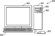
- the figure which shows an example of the display in the embodiment The schematic diagram which shows an example of the external appearance of the computer system in each said embodiment
- Embodiment 1 A numerical value input device according to Embodiment 1 of the present invention will be described with reference to the drawings.
- the numerical input device according to the present embodiment inputs two variables.
- FIG. 1 is a block diagram showing a configuration of a numerical input device 1 according to the present embodiment.
- the numerical value input device 1 according to the present embodiment includes an image data storage unit 11, an image generation unit 12, an image display unit 13, an instruction reception unit 14, a numerical value acquisition unit 15, an output unit 16, and a numerical value storage unit. 17 and a calculation unit 18.
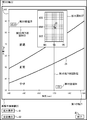
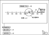
- the coordinate plane image data is image data of a coordinate plane having a first axis 21 and a second axis 22, for example, as shown in FIG.
- the numerical value input device 1 inputs a first variable corresponding to the first axis 21 and a second variable corresponding to the second axis 22.
- FIG. 5 shows a case where the first and second axes 21 and 22 are straight lines on the coordinate plane and the orthogonal coordinate system is orthogonal to each other, but this need not be the case.
- an oblique coordinate system may be used.
- the coordinate plane image data may be any data as long as it can display an image in the plane coordinate system as a result.
- the coordinate plane image data may be an image itself such as raster data, and is rasterized as vector data. It may be data that becomes an image.
- the first axis 21 is an axis indicating the height (cm) which is a variable.
- the second axis 22 is an axis indicating weight (kg) as a variable. Further, the second axis 22 is orthogonal to the first axis.
- the height is taken on the horizontal axis and the weight is taken on the vertical axis, but it goes without saying that it may be reversed. Further, as shown in FIG.
- information indicating that the variable indicated by the axis is height for example, a character string of “height” may be displayed near the first axis 21. .
- the scale and the numerical value may be displayed on the first axis 21 as shown in FIG. The same applies to the second axis 22, even if information indicating that the variable indicated by the axis is weight is displayed in the vicinity of the second axis 22, for example, a character string “weight” is displayed. Good.
- a scale and a numerical value may be displayed on the second axis 22.
- the first region boundary line 23 is a parabola that indicates the relationship between height and weight when the BMI is the first value.
- the second region boundary line 24 is a parabola showing the relationship between height and weight when the BMI is a second value.
- BMI weight (kg) / ⁇ height (m) ⁇ 2
- the coordinate plane is a predetermined function having the values of the first axis 21 and the value of the second axis 22 as arguments (in the present embodiment, the BMI function described above). ) May be divided into a plurality of regions according to the value of. Dividing into a plurality of areas according to the value of the calculation result of the predetermined function means that the area is divided into a plurality of areas for each range of values of the calculation result of the predetermined function as shown in FIG. It may be.
- the coordinate plane is divided into three regions by the first and second region boundary lines 23 and 24. That is, a region delimited by the second axis 22 and the first region boundary line 23 (this region will be referred to as “first region”), the second axis 22, and the first region A region delimited by a boundary line 23 and a second region boundary line 24 (this region will be referred to as a “second region”), a first axis 21, a second axis 22, The region is divided into two regions (hereinafter, this region is referred to as a “third region”).
- first region boundary line 23 is a region boundary line having a BMI of 25
- second region boundary line 24 is a region boundary line having a BMI of 18.5. Is a region where BMI is larger than 18.5 and smaller than 25, and the third region is a region where BMI is smaller than 18.5.
- each region may be easily visually distinguished by coloring the first to third regions with different colors or using different shades. .
- the first region is an “obese” region.
- the second region is a “normal” region because the BMI is larger than 18.5 and smaller than 25.
- the third region is a “slim” region. As shown in FIG. 5, the words “obesity”, “normal”, and “loss” characterizing each region may be displayed for each region.
- coordinate plane image data may be stored in the image data storage unit 11 via a recording medium, and coordinate plane image data transmitted via a communication line or the like is stored in the image data storage unit 11.
- coordinate plane image data input via an input device may be stored in the image data storage unit 11.
- Storage in the image data storage unit 11 may be temporary storage in a RAM or the like, or may be long-term storage.
- the image data storage unit 11 can be realized by a predetermined recording medium (for example, a semiconductor memory, a magnetic disk, an optical disk, etc.).
- the image generation unit 12 includes point graphic image data, enlarged graphic image data, first numerical image data, second numerical image data, function calculation result image data, and first drop line graphic image data. Second drop line graphic image data is generated. These data will be described with reference to FIGS.
- the point graphic image data is image data of the point graphic 31.
- the point graphic 31 is a graphic indicating the position on the coordinate plane of the coordinate plane image 20 indicated by the coordinate plane image data. By designating the position of the point graphic 31, both the value (height) of the first axis 21 and the value (weight) of the second axis 22 corresponding to the point graphic 31 are designated collectively. Will be able to.
- the point graphic 31 is displayed on the coordinate plane image 20, and it can be determined whether or not the person is obese by seeing in which region the point graphic 31 exists. As shown in FIG. 5, the point graphic 31 may be a point graphic (round graphic), or other graphic such as a cross, triangle, or square.
- the image generating unit 12 when the instruction receiving unit 14 described later receives an instruction to specify the position of the point graphic 31, the image generating unit 12 generates point graphic image data corresponding to the position specified by the instruction. That is, the image generation unit 12 generates the point graphic image data so that the point graphic 31 is moved to the position specified by the instruction received by the instruction reception unit 14 described later. Therefore, when the instruction receiving unit 14 (to be described later) receives an instruction to specify the position of the point graphic, the point graphic image data corresponding to the point graphic 31 that has been displayed so far is erased and newly specified. Point graphic image data corresponding to the position may be generated.
- the point graphic image data is image data of a point graphic, and may be an image itself such as raster data as long as the image data can finally display a point graphic. Data that becomes an image by being rasterized as shown in FIG.
- the point graphic image data may be generated on the coordinate plane image 20 indicated by the coordinate plane image data, or may be generated separately from the coordinate plane image 20. In the latter case, the point graphic image data preferably has information indicating the display position on the coordinate plane image 20.
- the point graphic image data may be temporarily stored in a recording medium (not shown), or may be temporarily stored in the image data storage unit 11. What is described in this paragraph is the same for other graphic data generated by the image generation unit 12.
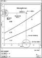
- the enlarged graphic image data is image data of the enlarged graphic 37.
- the enlarged figure 37 is a part of the coordinate plane, and is an enlarged figure of the area including the position of the point graphic 31.
- the user can input numerical values more finely than directly inputting numerical values on the coordinate plane. Therefore, as shown in FIG. 6, in each of the axes corresponding to the first and second axes 21 and 22 in the enlarged graphic 37, finer numerical values are displayed than the first and second axes 21 and 22. Will be.
- the enlarged graphic 37 may be displayed, for example, at the position of the point graphic 31 (for example, the position directly above the point graphic 31) or not. In the latter case, the enlarged graphic 37 may be displayed at a predetermined position (not necessarily on the coordinate plane image 20).
- the image generation unit 12 may generate the point graphic image data so that the point graphic 31 is displayed on the most front side.
- the first numerical image data is first numerical image data.
- the first numerical value is a value of the first axis 21 corresponding to the position of the point graphic 31 acquired by the numerical value acquisition unit 15 described later.
- this 1st numerical value 34 may be displayed in the vicinity of the position of the 1st axis
- the display position of the first numerical value 34 can be moved in accordance with the movement of the point graphic 31.
- the first numerical value 34 may always be displayed at a predetermined position.
- the first numerical image data is usually image data indicating numerical text.
- the second numerical image data is second numerical image data.
- the second numerical value 35 is a value of the second axis 22 corresponding to the position of the point graphic 31 acquired by the numerical value acquisition unit 15 described later. By displaying the second numerical value 35, the user can know the value of the second axis 22 input by the point graphic 31.
- the second numerical value 35 is the same as the first numerical value 34 described above except that the numerical value to be displayed is different, and detailed description thereof is omitted.
- the function calculation result image data is image data of a calculation result value of a predetermined function calculated by the calculation unit 18 described later.
- the user can know the value of the function calculation result corresponding to the values of the first and second axes 21 and 22 input by the point graphic 31. More specifically, for example, the BMI value corresponding to the height and weight input by the point graphic 31 can be known.
- the position where the value 36 of the function calculation result is displayed is not limited. For example, as shown in FIG. 5, it may be near the point graphic 31 or may be a predetermined position. .
- the function calculation result image data is usually image data indicating numerical text.
- the first drop line graphic image data is image data of the first drop line graphic 32.
- the first drop line graphic 32 is a graphic of a drop line (drop line) drawn from the point graphic 31 to the position of the first axis 21 corresponding to the point graphic 31.
- the value of the first axis 21 corresponding to the position of the point graphic 31 can be easily known by the intersection of the first drop line graphic 32 and the first axis 21.
- the second drop line graphic image data is image data of the second drop line graphic 33.
- the second drop line graphic 33 is a drop line graphic drawn from the point graphic 31 to the position of the second axis 22 corresponding to the point graphic 31.
- the value of the second axis 22 corresponding to the position of the point graphic 31 can be easily known by the intersection of the second drop line graphic 33 and the second axis 22.
- the first and second drop line figures 32 and 33 are usually drawn from the point figure 31 in parallel to the first and second axes 21 and 22, but as a result, correspond to the point figure 31. If the value of the 1st and 2nd axis
- the first and second drop line figures 32 and 33 are usually linear figures.
- the image generation unit 12 may generate the original graphic data stored in advance on a recording medium (not shown).
- the original image data may be, for example, image data of a graphic used as a point graphic (for example, a circular graphic), and may be an image such as a frame or grid line used when generating enlarged graphic image data. It may be data, may be image data of a frame used when generating first and second numerical image data and function calculation result image data, or other image data.
- the image display unit 13 displays the coordinate plane image data read from the image data storage unit 11 and each image data such as the point graphic image data generated by the image generation unit 12. It is assumed that the image display unit 13 performs display output for finally performing image display related to coordinate plane image data and the like. Therefore, the image display unit 13 may be, for example, a transmission unit that transmits image data or the like to a display device (for example, a CRT or a liquid crystal display). Further, the image display unit 13 may or may not include a display device that performs the display. The image display unit 13 may be realized by hardware, or may be realized by software such as a driver that drives a display device.
- the image generation unit 12 may sequentially store the generated image data in a recording medium from which the image display unit 13 described later reads the image data.
- the image display unit 13 can display the image data only by reading and displaying the image data from the recording medium. It becomes like this.
- the recording medium may be the image data storage unit 11.
- the instruction receiving unit 14 receives an instruction for designating the position of the point graphic displayed by the image display unit 13.
- an instruction regarding the position of the point graphic 31 on the coordinate plane may be received with a mouse, a trackpad, a touch panel, an arrow key, or the like.
- the instruction regarding the position of the point graphic 31 may be, for example, an instruction for determining the position of the point graphic 31 (for example, clicking on the position of the point graphic 31), or the position of the point graphic 31 is moved. It may be an instruction (for example, dragging a point graphic 31 displayed in advance).
- the instruction receiving unit 14 may receive an instruction as to whether or not to display the enlarged graphic image data. That is, for example, the instruction receiving unit 14 may receive an instruction to display enlarged graphic image data or an instruction to display no enlarged graphic image data.
- the image generation unit 12 may or may not generate the enlarged graphic image data in response to an instruction on whether or not to display the enlarged graphic image data, or the image display unit 13 may generate the enlarged graphic image data.
- Image data may be displayed or not displayed. That is, the process is not limited as long as the display is performed in accordance with the instruction on whether to display the enlarged graphic image data.
- the instruction receiving unit 14 may receive information input from an input device (for example, a keyboard, a mouse, a touch panel, etc.), or may receive information transmitted via a wired or wireless communication line. .
- the instruction receiving unit 14 may or may not include a device (for example, a modem or a network card) for receiving.
- the instruction receiving unit 14 may be realized by hardware, or may be realized by software such as a driver that drives a predetermined device.
- the numerical value acquisition unit 15 acquires a first numerical value that is the value of the first axis 21 corresponding to the position of the point graphic 31 on the coordinate plane and a second numerical value that is the value of the second axis 22.
- the value of the axis corresponding to the position of the point graphic 31 is, for example, in the case of the first axis 21, a straight line is drawn parallel to the second axis 22 from the point graphic 31, and the straight line and the first axis 21. It may be a value corresponding to the intersection with. Similarly, in the case of the second axis 22, it may be a value corresponding to the intersection of the straight line and the second axis 22 by drawing a straight line from the point graphic 31 in parallel to the first axis 21.
- the numerical value acquisition unit 15 may acquire the first and second numerical values by detecting the position of the point graphic 31 on the display screen and converting the position into a position on the coordinate plane. In this case, the numerical value acquisition unit 15 determines the position of the point graphic 31 on the display screen according to whether the point graphic 31 exists on the enlarged graphic 37 or on the coordinate plane. The method of converting to a numerical value of 2 may or may not be changed. That is, if the point graphic 31 exists on the enlarged graphic 37, the first and second numerical values are acquired using the coordinates of the enlarged graphic 37, and if the point graphic 31 exists on the coordinate plane. The first and second numerical values may or may not be acquired using the coordinates of the coordinate plane.
- the output unit 16 outputs the first and second numerical values acquired by the numerical value acquiring unit 15.
- the output may be, for example, display on a display device (for example, a CRT or a liquid crystal display), transmission via a communication line to a predetermined device, printing by a printer, or audio output by a speaker. Alternatively, it may be stored in a recording medium or delivered to another component.
- the output unit 16 may or may not include an output device (for example, a display device or a printer).
- the output unit 16 may be realized by hardware, or may be realized by software such as a driver that drives these devices.
- the numerical value storage unit 17 stores the first and second numerical values accumulated by the output unit 16 as described above. Storage in the numerical value storage unit 17 may be temporary storage in a RAM or the like, or may be long-term storage.
- the numerical value storage unit 17 can be realized by a predetermined recording medium (for example, a semiconductor memory, a magnetic disk, an optical disk, etc.).
- the calculation unit 18 calculates a value of a calculation result of a predetermined function using the first and second numerical values acquired by the numerical value acquisition unit 15 as arguments.
- This predetermined function is preferably the same as the predetermined function used when the coordinate plane is divided into a plurality of regions, but this need not be the case.
- the former case that is, a case where the predetermined function is a BMI equation will be described.
- the predetermined function is stored in a recording medium (not shown), and the calculation unit 18 may calculate the value of the function calculation result from the first and second numerical values by reading the predetermined function. Good.
- the image data storage unit 11 and the numerical value storage unit 17 may be realized by the same recording medium or may be realized by separate recording media.
- the area storing the coordinate plane image data is the image data storage unit 11
- the area storing the first and second numerical values is the numerical value storage unit 17.
- Step S101 The image display unit 13 determines whether to display coordinate plane image data or the like. If so, the process proceeds to step S102. If not, the process of step S101 is repeated until it is determined to be displayed.
- the image display unit 13 may determine to output the coordinate plane image data or the like when receiving an instruction to display the coordinate plane image data or the like, for example, or may display the coordinate plane image data or the like at other timing. May be determined to be displayed.
- Step S102 The image display unit 13 displays the coordinate plane image data read from the image data storage unit 11 and the image data generated by the image generation unit 12.
- coordinate plane image data or the like When coordinate plane image data or the like is displayed for the first time, the point graphic 31 at a predetermined position, the first and second drop line graphics 32 and 33, and the first and second numerical values corresponding thereto. 34, 35, the value 36 of the function calculation result, etc. may be displayed, or they may not be displayed.
- Step S103 The instruction receiving unit 14 determines whether an instruction for specifying the position of the point graphic 31 has been received. If accepted, the process proceeds to step S104, and if not, the process proceeds to step S109.
- Step S104 The image generation unit 12 generates image data such as a point graphic in accordance with the received instruction. Details of this processing will be described later with reference to the flowchart of FIG.
- the numerical value acquisition unit 15 acquires first and second numerical values corresponding to the position of the point graphic 31.
- the numerical value acquisition unit 15 acquires the coordinate value of the screen coordinate corresponding to the position of the point graphic 31.
- the acquisition of the coordinate value may be performed by, for example, an operation system (OS).
- OS operation system
- the screen coordinates are a coordinate system in which the upper left end point of the display screen on which the coordinate plane image 20 or the like is displayed is the origin, the X axis is the right direction, and the Y axis is the lower direction. Further, for example, with the upper left end point of the coordinate system shown in FIG.
- the client coordinates that are the coordinate system are set.
- the numerical value acquisition unit 15 converts the acquired coordinate value of the screen coordinate into the coordinate value of the client coordinate.
- the numerical value acquisition unit 15 acquires the first numerical value (height value) and the second numerical value (weight value) by converting the client coordinates into (height, weight) coordinate values. can do.
- the conversion from the coordinate value of the screen coordinate to the coordinate value of the client coordinate is already known, and a detailed description thereof will be omitted.
- Step S106 The output unit 16 outputs the first and second numerical values acquired by the numerical value acquiring unit 15. In other words, the output unit 16 accumulates the first and second numerical values in the numerical value storage unit 17.
- Step S107 The calculation unit 18 calculates a value of a calculation result of a predetermined function using the first and second numerical values acquired by the numerical value acquisition unit 15.
- Step S108 The image generation unit 12 generates image data or the like of the value 36 of the function calculation result. Details of this processing will be described later with reference to the flowchart of FIG. Then, the process returns to step S102.
- Step S109 The instruction receiving unit 14 determines whether an instruction related to display or non-display of the enlarged graphic 37 has been received. And when it receives, it progresses to step S110, and when that is not right, it progresses to step S113.
- Step S110 The image generation unit 12 determines whether the instruction regarding the enlarged graphic 37 received by the instruction receiving unit 14 is an instruction to display the enlarged graphic 37. If the instruction is to display the enlarged graphic 37, the process proceeds to step S111. If not, that is, if the instruction is to delete the enlarged graphic 37, the process proceeds to step S112.
- Step S111 The image generation unit 12 newly generates image data of the enlarged graphic 37. Then, the process returns to step S102. As a result, the enlarged graphic 37 is displayed.
- Step S112 The image generation unit 12 erases the enlarged figure 37 that has been displayed so far. Then, the process returns to step S102. As a result, the enlarged graphic 37 that has been displayed until then is deleted.
- Step S113 The image display unit 13 determines whether or not to finish displaying the coordinate plane image data and the like. If the process is to end, the process returns to step S101; otherwise, the process returns to step S103. Note that the image display unit 13 may determine to end the display of the coordinate plane image data or the like when receiving an instruction to end the display of the coordinate plane image data or the like. When a predetermined time has elapsed since the last display, the display of the coordinate plane image data and the like may be determined to end. In the flowchart of FIG. 2, the process is terminated by powering off or a process termination interrupt.
- FIG. 3 is a flowchart showing details of the process of generating a point graphic or the like (step S104) in the flowchart of FIG.
- the image generation unit 12 generates point graphic image data in response to an instruction specifying the position of the point graphic 31 received by the instruction receiving unit 14. For example, when the received instruction is an instruction to move the point graphic 31, the image generation unit 12 deletes the point graphic image data at that time, and moves the point graphic image data to the position of the movement destination. Is generated. For example, when the received instruction is an instruction to newly display the point graphic 31, the image generation unit 12 generates the point graphic image data at the designated position.
- the point graphic image data may be generated using, for example, the point graphic 31 stored in advance on a recording medium (not shown).
- the generation of the point graphic image data may be, for example, a process for determining the display position of the point graphic 31.
- Step S202 The image generation unit 12 performs first and second image data of first and second drop line graphics 32 and 33 extending from the point graphic 31 to the first and second axes 21 and 22, respectively.
- Dropline graphic image data is generated.
- the X-axis value of the screen coordinate corresponding to the point graphic 31 is A
- the Y-axis value is B
- the first axis 21 exists on a straight line where the Y-axis of the screen coordinate is C.
- the image generation unit 12 performs the first drop that is a line segment from (A, B) to (A, C).
- First drop line graphic image data for displaying the line graphic 32 may be generated.
- the image generator 12 generates second drop line graphic image data for displaying the second drop line graphic 33 that is a line segment from (A, B) to (D, B). Also good. Note that client coordinates may be used instead of screen coordinates. And it returns to the flowchart of FIG.
- FIG. 4 is a flowchart showing details of processing for generating a function image or the like (step S108) in the flowchart of FIG.
- the image generation unit 12 generates first numerical image data and second numerical image data using the first and second numerical values acquired by the numerical value acquisition unit 15.
- the image generation unit 12 reads, for example, original image data that is graphic image data such as a frame stored in advance on a recording medium (not shown), and the first numerical value or the second numerical text is added to the image data. By inserting, the first and second numerical image data may be generated.
- the display positions of the first and second numerical values 34 and 35 are set so as to be in the vicinity of the first numerical value of the first axis 21 and in the vicinity of the second numerical value of the second axis 22, respectively. Also good. In this case, the display positions of the first and second numerical values 34 and 35 may be determined by performing conversion from the coordinate system of the first and second axes 21 and 22 to client coordinates.
- Step S302 The image generation unit 12 generates function calculation result image data using the value of the calculation result of the function calculated by the calculation unit 18.
- the image generation unit 12 reads, for example, original image data that is graphic image data such as a frame stored in a recording medium (not shown) in advance, and inserts a text of a value of a function calculation result into the image data.
- the function calculation result image data may be generated by The display position of the function calculation result value 36 may be set so as to be in the vicinity of the point graphic 31.
- Step S303 The image generation unit 12 determines whether or not the enlarged graphic 37 is being displayed. That is, it is determined whether or not the enlarged graphic image data is included in the image to be displayed by the image display unit 13. If the enlarged graphic 37 is being displayed, the process proceeds to step S304, and if not, the process returns to the flowchart of FIG.
- the image generation unit 12 generates enlarged graphic image data that is image data of the enlarged graphic 37.
- the image generation unit 12 reads, for example, original image data that is image data such as a frame graphic stored in advance on a recording medium (not shown), and a predetermined position (for example, a center point) of the image data is read out.
- Image data such as broken grid lines and coordinate values is generated so as to be coordinate values of the point graphic 31 (this is the coordinate values of the first and second axes 21 and 22).
- the image generation unit 12 reads image data of a graphic such as a frame and arranges image data of broken grid lines in the frame according to the coordinate value of the point graphic 31.
- the image data of the broken grid lines is arranged so that the position of the point graphic 31 is the intersection of the grid lines, and the point If any of the coordinate values of the graphic 31 is not an integer, the image data of broken grid lines is arranged by shifting by that amount.
- the number after the decimal point of the coordinates in the direction of the first axis 21 is A and the grid lines are provided in integer units of the value of the first axis 21, the intersection of the grid lines is the first
- the grid line may be set so that the value of the first axis 21 is shifted by A / 10, which is one unit of the grid line in the direction of the axis 21.
- the image generation unit 12 uses the unit length of the grid line and the coordinate value of the point graphic 31 so that the grid line included in the enlarged graphic image data has an integer, every “5”, or A line corresponding to the value of the first axis 21 every “10” can be specified. Then, the image generation unit 12 may arrange image data of text having coordinate values in association with the specified line.
- the coordinate value of the point figure 31 can be known from the first and second numerical values acquired by the numerical value acquiring unit 15, for example.
- the image generating unit 12 is configured so that the location of the point graphic 31 on the enlarged graphic 37 becomes the location of the point graphic 31 on the coordinate plane constituted by the first and second axes 21 and 22. The display position of 37 may be determined. And it returns to the flowchart of FIG.
- step S111 the generation of the enlarged graphic image data in the above-described step S111 is performed in the same manner as described in step S304. Further, in the flowchart of FIG. 4, the order of processing in step S301, step S302, and steps S303 and S304 does not matter.
- the image display unit 13 displays each image data on a display.
- the user inputs an instruction to output the coordinate plane image 20 to the numerical input device 1 by operating a mouse or a keyboard.
- the image display unit 13 determines that it is time to display the image data (step S101), reads the coordinate plane image data from the image data storage unit 11, and outputs it to the display (step S102).
- the coordinate plane image 20 shown in FIG. 5 includes a point graphic 31, first and second drop line graphics 32, 33, first and second numerical values 34, 35, and a function calculation result value 36. A screen without the display of is displayed on the display.
- step S104 the image generation unit 12 performs processing for generating a point graphic or the like. Specifically, the image generation unit 12 generates point graphic image data at the position clicked with the mouse (step S201). Here, it is assumed that the position where the height value is “170 (cm)” and the weight value is “85.0 (kg)” is clicked.
- the image generation unit 12 also includes first and second image data of first and second drop line graphics 32 and 33 extending perpendicularly from the point graphic 31 to the first and second axes 21 and 22, respectively. Dropline graphic image data is generated (step S202).
- the numerical value acquisition unit 15 acquires the first numerical value “170” and the second numerical value “85.0” corresponding to the point graphic 31 on the coordinate plane (step S105).
- the first and second numerical values are accumulated in the numerical value storage unit 17 by the output unit 16 (step S106).
- the calculation unit 18 calculates the value of the calculation result of the predetermined function, that is, the BMI value (step S107).
- the BMI value is “29.4”.
- the image generation unit 12 performs processing for generating function calculation result image data and the like (step S108). Specifically, the image generation unit 12 generates first and second numerical image data corresponding to the first and second numerical values acquired by the numerical value acquisition unit 15 (step S301). Further, the image generation unit 12 generates function calculation result image data corresponding to the BMI value calculated by the calculation unit 18 (step S302). Here, since the enlarged graphic 37 is not displayed, the process of generating the enlarged graphic image data is not performed (step S303).
- the image display unit 13 displays image data such as the point graphic 31 generated by the image generation unit 12 on the display (step S102). As a result, the display shown in FIG. 5 is performed.
- the instruction receiving unit 14 receives an instruction to display the enlarged graphic 37 (step S109).
- the instruction receiving unit 14 uses the information that associates the position of the “enlarged display” button 41 and the type of the button 41 stored in a recording medium (not shown) to position the “enlarged display” button 41. When is clicked, it may be detected that the “enlarged display” button 41 is clicked. The same applies to the other buttons.
- the image generation unit 12 determines that the instruction is to display the enlarged graphic 37 (step S110), and generates enlarged graphic image data corresponding to the position of the point graphic 31 shown in FIG. 5 (step S111). ). Then, the enlarged graphic 37 is displayed on the display as shown in FIG. 6 (step S102). In the enlarged graphic 37, since the periphery of the position of the point graphic 31 is enlarged, the user can position the point graphic 31 in more detail. As a result, more detailed numerical input can be realized.
- the position of the point graphic 31 is not the position intended by the user, for example, the height value is “174 (cm)” and the weight value is “86.6 (kg)”.
- the user moves the point graphic 31 by dragging the point graphic 31 with a mouse or the like in the display of FIG. 6 or by clicking a point on a new target coordinate plane.
- the image generation unit 12 generates point graphic image data and first and second drop line graphic image data at the moved position (steps S103 and S104).
- the numerical value acquisition unit 15 acquires first and second numerical values corresponding to the position of the point graphic 31 (step S105).
- the first and second numerical values are accumulated in the numerical value storage unit 17 by the output unit 16 (step S106). Further, the calculation unit 18 calculates a BMI value using the acquired first and second numerical values (step S107). Then, the image generation unit 12 generates first and second numerical image data, function calculation result image data, and enlarged graphic image data displayed at the position of the point graphic 31 after movement (step S108, They are displayed on the display (step S102).
- the point graphic 31 is moved at a stretch has been described, but this need not be the case.
- a trajectory in the middle of the user dragging the point graphic 31 may be sequentially displayed by the image display unit 13. As described above, the point graphic 31 may be moved by repeating the processes of steps S102 to S108.
- the image generation unit 12 generates enlarged graphic image data in which the display position is changed according to the position of the point graphic 31.
- the point graphic 31 is always displayed at the center of the enlarged graphic 37.
- the height and weight values on the enlarged graphic 37 indicated by the point graphic 31 and the first and second axes 21 are displayed.
- step S105 the numerical value acquisition unit 15 sets the client coordinates on the coordinate plane formed by the first and second axes 21 and 22 as the client coordinates. It is only necessary to obtain the first and second numerical values.
- the first and second numerical values corresponding to the position of the point graphic 31 on the enlarged graphic 37 are set according to the first and second numerical values.
- step S105 processing in the flowchart of FIG. 2
- the acquisition method differs depending on whether or not the enlarged graphic is displayed. That is, it is necessary to obtain the first and second numerical values as in the flowchart of FIG.
- the flowchart of FIG. 9 will be described.
- Step S401 The numerical value acquisition unit 15 determines whether or not the enlarged graphic 37 is displayed. And when it is displayed, it progresses to step S402, and when that is not right, it progresses to step S403.
- Step S402 The numerical value acquisition unit 15 acquires the first and second numerical values using the coordinate system of the enlarged figure 37. Therefore, in this case, the coordinate system of the enlarged figure 37 is used as the client coordinates, and the conversion from the screen coordinates to the client coordinates, the processing of converting the coordinate values of the client coordinates into the height and weight values, and the like are performed. And it returns to the flowchart of FIG.
- Step S403 The numerical value acquisition unit 15 acquires the first and second numerical values in the same manner as described in step S105, and returns to the flowchart of FIG.
- the processes of steps S303 and S304 in the flowchart of FIG. 4 do not have to be performed.
- the enlarged graphic 37 may be newly generated or not. In the former case, for example, a new centered on the position on the coordinate plane constituted by the first and second axes 21 and 22 corresponding to the position of the enlarged figure 37 where the point figure 31 was present last.
- the image generation unit 12 may generate enlarged graphic image data so that the enlarged graphic 37 is displayed.
- step S109, S110, S112, S102 When the user clicks the “overall display” button 42 in the display of FIG. 6, the enlarged graphic image data is erased accordingly, and the enlarged graphic 37 is not displayed as shown in FIG. 5 (step S109, S110, S112, S102). Further, when the user clicks the “end” button 43 in the display of FIG. 5, the display of the coordinate plane image 20 and the like is ended accordingly and is not displayed on the display (step S113).
- the height and weight values input as in the above specific example may be added to a database corresponding to the input user, or other usage may be performed.
- the numerical value input device 1 it is possible to input the first and second numerical values using the GUI on the coordinate plane without using a numeric keypad.
- a numeric keypad For example, when inputting numerical values in a browser, etc., there is an advantage that numerical values can be input by operating only the pointing device without using both a pointing device and a keyboard such as a numeric keypad. is there.
- by displaying the enlarged graphic 37 it becomes possible to easily input fine numerical values. Further, as shown in FIG.
- the coordinate plane is divided into a plurality of regions by the first and second region boundary lines 23 and 24, so that the value of the calculation result of the function corresponding to the input value is obtained.
- Attributes for example, “obesity”, “normal”, “loss”, etc.
- the first and second numerical values 34 and 35 it is possible to easily know the input accurate values.
- the function calculation result value 36 it is possible to easily know the value of the function calculation result corresponding to the input numerical value.
- the first and second drop line graphics 32 and 33 the positions of the first and second axes 21 and 22 corresponding to the position of the point graphic 31 can be easily specified. It becomes like this.
- the enlarged graphic 37 is a partial area of the coordinate plane, an outline of the position of the point graphic 37 with respect to the entire coordinate plane is displayed even when the enlarged graphic 37 is displayed. There is also an advantage that can be easily grasped.
- the enlargement ratio of the enlarged figure 37 may be changeable.
- the enlargement ratio may be increased or decreased by the enlargement ratio changing slider 44.
- the enlarged graphic 37 can be displayed at the user's preferred magnification.
- the image data of a plurality of enlarged figures corresponding to the enlargement ratio may be stored in advance in a recording medium (not shown), or the image data of the original enlarged figure is used to correspond to the enlargement ratio. You may make it produce
- the numerical value acquisition unit 15 acquires the first and second numerical values according to the magnification ratio of the enlarged graphic 37.
- the client coordinates are changed according to the enlargement ratio of the enlarged figure 37, and the numerical value acquisition unit 15 acquires the first and second numerical values using the coordinate values of the client coordinates after the change.
- the client coordinates themselves are not changed, and the correspondence between the client coordinates and the coordinates in the enlarged figure 37 may be changed. It is assumed that the enlargement ratio of the enlarged figure can be changed in the following embodiments.
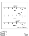
- the case where the enlarged graphic 37 in which the position of the point graphic 31 is enlarged has been described. However, as shown in FIG. 11, it is a part of the first and second axes 21 and 22. Then, numerical values may be input using the first and second enlarged figures 38 and 39 in which the area including the position corresponding to the point figure 31 is enlarged. In this case, the first and second enlarged figures 38 and 39 may be displayed at all times. That is, in the flowchart of FIG. 2, the processing of steps S109 to S112 need not be performed. Further, in the flowchart of FIG. 4, the process of step S304 may always be performed. That is, the process of step S303 may be deleted and the process may proceed from step S302 to step S304.
- the method for generating the first and second enlarged graphic image data for displaying the first and second enlarged graphics 38 and 39 is the same as the method for generating the enlarged graphic image data, and a detailed description thereof is provided. Is omitted.
- the first and second enlarged graphic 38, 39 may move according to the movement of the point graphic 31, or may not move. In the latter case, as shown in FIG. 12, the first falling line figure 32 may be shifted at the boundary of the enlarged figure.
- the numerical value input apparatus 1 also includes the image data storage unit 11, the image generation unit 12, the image display unit 13, the instruction reception unit 14, the numerical value acquisition unit 15, the output unit 16, and the numerical value.
- a storage unit 17 and a calculation unit 18 are provided.
- coordinate axis image data is also stored in addition to the coordinate plane image data.
- the coordinate plane image data is image data of a coordinate plane having a first axis and a second axis as described above.
- the coordinate axis image data is image data of the coordinate axis of the third axis.
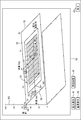
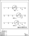
- the coordinate plane image data and the coordinate axis image data may constitute a coordinate system in a three-dimensional space, or may not be so. In the present embodiment, the former case will be described. Therefore, for example, the coordinate plane image data and the coordinate axis image data form a coordinate space having the first axis 51, the second axis 52, and the third axis 53, as shown in FIG.
- the numerical input device 1 has a first variable corresponding to the first axis 51, a second variable corresponding to the second axis 52, and a third variable corresponding to the third axis 53. Input with the variable. However, in the present embodiment, first, the third variable corresponding to the third axis 53 is input, and then the first and second variables corresponding to the first and second axes 51 and 52 are input. Shall be entered. In FIG.
- the first to third axes 51 to 53 are straight lines and are orthogonal coordinate systems in which they are orthogonal (however, a three-dimensional orthogonal coordinate system is converted into a two-dimensional plane
- a three-dimensional orthogonal coordinate system is converted into a two-dimensional plane
- an oblique coordinate system may be used.
- the first axis 51 is an axis indicating a variable height (cm)
- the second axis 52 is an axis indicating a variable body weight (kg)
- the third axis 53 is a variable. It is an axis indicating the age.
- any axis may be assigned to any variable.
- the names of variables indicated by the axes may be displayed near each axis, and a scale and a numerical value may be displayed on each axis.
- the formula indicating the basic energy amount is known as the Harris-Benedict formula and is as follows (however, it is a formula for men).
- Basic energy (kcal / day) 66.47 + 13.75 x body weight (kg) + 5.003 x height (cm) -6.775 x age
- the basic energy amount having a constant value is a plane in a coordinate system with height, weight, and age as three axes. Therefore, for example, on the coordinate space shown in FIG. 15, the relationship between height, weight, and age when the basic energy amount is a certain value (this value is referred to as “boundary value”) is shown.
- a region boundary surface that is a plane may be displayed or may not be displayed. In the present embodiment, the latter case will be described.
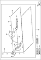
- the coordinate plane image data is a predetermined function (in this embodiment, the above Harris / Harris) with the values of the first axis 51, the second axis 52, and the third axis 53 as arguments. Benedict's equation), and coordinates that are divided into a plurality of regions according to the value of the calculation result of the function obtained by substituting the third numerical value acquired by the numerical value acquisition unit 15 described later for the value of the third axis 53
- It may be plane image data.
- the coordinate plane is divided into two regions by the intersection line between the coordinate plane of the coordinate plane image data and the region boundary surface.
- the boundary value is “1200 (kcal / day)”.
- this value may be another appropriate value.
- the coordinate plane is divided into two regions by a region boundary line 78. That is, a region where the basic energy amount is greater than 1200 (kcal / day) (on the right side of the region boundary line 78 in FIG. 16) and a region smaller than 1200 (kcal / day) (the left side of the region boundary line 78 in FIG. 16). And divided. Each region may be visually distinguished easily by coloring with a different color or with different shading.
- the wording “basic energy amount: large” characterizing the region may be displayed, and a region where the basic energy amount is smaller than 1200 (kcal / day). May display the wording “basic energy amount: small” characterizing the region.
- the image generation unit 12 includes the point graphic image data, the enlarged graphic image data, the first to third numerical image data, the function calculation result image data, and the first and second image data. Dropline graphic image data is generated. These data will be described with reference to FIGS. 15 to 17.
- the point graphic image data is image data of the point graphic 61.
- the point graphic 61 is a graphic indicating the position on the coordinate plane indicated by the coordinate plane image data, the position on the coordinate axis indicated by the coordinate axis image data, and the like.
- the position of the point graphic 61 By specifying the position of the point graphic 61, the value of the third axis 53 corresponding to the point graphic 61 and the values of the first and second axes 51 and 52 can be specified.
- a point graphic for specifying a position on the third axis 53 and the first and second axes 51 and 52 are described.
- Numerical values may be input using two point graphics including a point graphic for specifying a position on a coordinate plane constituted by:
- the description of the other point graphic 61 is the same as the description of the point graphic 31 of the first embodiment, and the description thereof is omitted.
- the enlarged graphic image data is image data of the enlarged graphic 79.
- the enlarged graphic 79 is a partial area of the coordinate plane constituted by the first and second axes 51 and 52 and is an enlarged graphic of the area including the position of the point graphic 61.
- the enlarged graphic 79 is the same as the enlarged graphic 37 of the first embodiment, and a description thereof is omitted.
- the first to third numerical image data are image data of the first to third numerical values 66, 67, and 68, respectively.
- the first to third numerical values are values of the first to third axes 51 to 53 corresponding to the position of the point graphic 61 acquired by the numerical value acquiring unit 15 described later.
- the first to third numerical image data are the same as the first and second numerical image data of the first embodiment, and the description thereof is omitted.
- the first to third numerical values 66 to 68 may be displayed in the vicinity of the positions of the first to third axes 51 to 53 corresponding to the first to third numerical values, for example. May be.
- the function calculation result image data is image data of a value 36 of a predetermined function calculation result calculated by the calculation unit 18 described later.
- This function calculation result image data is the same as the function calculation result image data of the first embodiment, and a description thereof will be omitted.
- the first and second drop line graphic image data are image data of the first and second drop line graphic 76 and 77, respectively.
- the first and second drop line figures 76 and 77 are drop line figures drawn from the point figure 61 to the first and second axes 51 and 52, respectively.
- the first and second falling line graphic image data is the same as the first and second falling line graphic data of the first embodiment, and the description thereof is omitted.
- the image generation unit 12 may generate enlarged graphic image data in which the display position is changed in accordance with the position of the point graphic 61, or the position of the point graphic 61 is within an enlarged area of the enlarged graphic 79. In this case, it is not necessary to change the position of the enlarged graphic 79 as in the first embodiment. In the present embodiment, as in the first embodiment, the former case will be described.
- the image generation unit 12 may generate image data of the region boundary line 78.
- the image generation unit 12 sets a boundary value (1200 kcal / day in the present embodiment) to a value (basic energy amount in the present embodiment) of a predetermined function (in this embodiment, Harris Benedict formula).
- a predetermined function in this embodiment, Harris Benedict formula.
- Substituting and generating image data of the region boundary line 78 by generating image data of the locus on the coordinate plane of the function obtained by substituting the third numerical value acquired by the numerical value acquisition unit 15 for the value of the third axis 53 can do.
- the generated image data of the region boundary line 78 may be added to the coordinate plane image data stored in the image data storage unit 11. Note that the image generation unit 12 may not generate the image data of the region boundary line 78.
- image data of the region boundary line 78 corresponding to various third numerical values is included in the coordinate plane image data stored in the image data storage unit 11 in advance, and the image display unit 13 displays the coordinate plane image.
- the region boundary line 78 may be displayed on the coordinate plane by reading the image data of the region boundary line 78 corresponding to the third numerical value acquired by the numerical value acquisition unit 15.
- the image display unit 13 is the same as that of the first embodiment except that the coordinate axis image data read from the image data storage unit 11 and the third numerical image data are also displayed, and the description thereof is omitted.
- the image display unit 13 may display the coordinate plane image data and the coordinate axis image data so that the first to third axes 51 to 53 form a coordinate space, or display them separately. May be.
- the image display unit 13 determines the third axis 53 in advance.
- the coordinate plane image data may or may not be displayed at the position. In the latter case, for example, the image display unit 13 positions the third axis 53 corresponding to a third numerical value acquired by a numerical value acquisition unit 15 described later (the acquisition of the third numerical value will be described later).
- coordinate plane image data may be displayed.
- the instruction receiving unit 14 may receive an instruction to end the input to the third axis 53 in addition to the same processing as the instruction receiving unit 14 of the first embodiment. This is because in the present embodiment, first, numerical values for the third axis 53 are received, and thereafter, numerical values for the first and second axes 51 and 52 are received.
- the numerical value acquisition unit 15 acquires a third numerical value that is a value of the third axis 53 corresponding to the position of the point graphic 61 and is on a coordinate plane constituted by the first and second axes 51 and 52.
- a first numerical value that is the value of the first axis 51 corresponding to the position of the point graphic 61 and a second numerical value that is the value of the second axis 52 are acquired.
- the method by which the numerical value acquisition unit 15 acquires numerical values is the same as in the first embodiment, and a description thereof is omitted.
- the point graphic 61 may exist on the third axis 53, or may exist on the coordinate space.
- the former case will be described. That is, when inputting the third variable, the image generation unit 12 restricts the movement of the point graphic 61 so that the point graphic 61 can move only on the third axis 53. .
- the image generation unit 12 may generate drop line graphic image data that is graphic data of a drop line with respect to the third axis 53 from the point graphic 61.
- the output unit 16 also outputs the third numerical value acquired by the numerical value acquiring unit 15.
- the rest is the same as in the first embodiment, and the description thereof is omitted.
- the calculation unit 18 calculates a value of a calculation result of a predetermined function using the first to third numerical values acquired by the numerical value acquisition unit 15 as arguments.
- the predetermined function is a Harris Benedict formula for calculating a basic energy amount from height, weight, and age.
- steps S501 to S504 are the same as those in the flowchart of FIG. 2 of the first embodiment except for the above-described differences such as displaying the coordinate axis image data together with the coordinate plane image data. Description is omitted.
- Step S501 The instruction receiving unit 14 determines whether an instruction for specifying the position of the point graphic 61 has been received. If accepted, the process proceeds to step S502, and if not, the process proceeds to step S503. In the present embodiment, as described above, it is assumed that the point graphic 61 is set to be movable only on the third axis 53 when the instruction to the point graphic 61 is received. .
- Step S502 The image generation unit 12 generates image data such as a point graphic in accordance with the received instruction. Details of this processing will be described later with reference to the flowchart of FIG.
- Step S503 The instruction receiving unit 14 determines whether an instruction to end the input to the third axis 53 has been received. If the input to the third shaft 53 is to be terminated, the process proceeds to step S504. If not, the process returns to step S501.
- Step S504 The image display unit 13 displays the coordinate plane image data and coordinate axis data read from the image data storage unit 11 and the image data generated by the image generation unit 12. Note that the image display unit 13 displays the coordinate plane 75 corresponding to the coordinate plane image data at the position of the third axis 53 corresponding to the third numerical value acquired in the processing of steps S501 to S503. . In addition, when the image display unit 13 displays the coordinate plane image data and the like for the first time, the point graphic 61 at a predetermined position, the first and second drop line graphics 76 and 77 corresponding thereto, The first and second numerical values 66 and 67, the value 69 of the function calculation result, and the like may be displayed.
- FIG. 14 is a flowchart showing details of the process of generating a point graphic or the like (step S502) in the flowchart of FIG.
- Step S601 The image generation unit 12 generates point graphic image data in response to an instruction specifying the position of the point graphic 61 received by the instruction receiving unit 14. For example, when the received instruction is an instruction to move the point graphic 61, the image generation unit 12 deletes the point graphic image data at that time, and moves the point graphic image data to the destination position. Is generated. For example, when the received instruction is an instruction to newly display the point graphic 61, the image generation unit 12 generates the point graphic image data at the specified position.
- the point graphic image data may be generated using, for example, a point graphic 61 stored in advance on a recording medium (not shown). The generation of the point graphic image data may be, for example, a process for determining the display position of the point graphic 61.
- the numerical value acquisition unit 15 acquires a third numerical value corresponding to the position of the point graphic 61.
- the numerical value acquisition unit 15 acquires the coordinate value of the screen coordinate corresponding to the position of the point graphic 61.
- the coordinate value of the screen coordinate is converted into the coordinate value of the client coordinate.
- the lower limit value (“0” in FIG. 15) and the upper limit value (“100” in FIG. 15) of the third axis 53 are associated with the coordinate values of the client coordinates corresponding to them. And Therefore, the numerical value acquisition unit 15 can acquire the value of the corresponding third axis 53 from the coordinate value of the client coordinate using the correspondence.
- Step S603 The output unit 16 outputs the third numerical value acquired by the numerical value acquiring unit 15. That is, the output unit 16 accumulates the third numerical value in the numerical value storage unit 17.
- the image generation unit 12 generates the third numerical image data using the third numerical value acquired by the numerical value acquisition unit 15.
- the image generation unit 12 reads, for example, original image data that is graphic image data such as a frame stored in a recording medium (not shown) in advance, and inserts a third numerical text into the image data.
- Third numerical image data may be generated.
- the display position of the third numerical value 68 may be set to be close to the third numerical value of the third axis 53. In this case, the display position of the third numerical value 68 may be determined by performing conversion from the coordinate system of the third axis 53 to client coordinates. And it returns to the flowchart of FIG.
- the image display unit 13 displays each image data on the display.
- the user inputs an instruction to output the coordinate space image 50 to the numerical input device 1 by operating a mouse or a keyboard.
- the image display unit 13 determines that it is time to display the image data (step S101), reads the coordinate plane image data and the coordinate axis image data from the image data storage unit 11, and outputs them to the display (step S102). ).
- the display shown in FIG. 15 is performed. In this display, a screen without displaying the point graphic 61 and the third numerical value 68 is displayed on the display.
- step S501 the instruction receiving unit 14 determines that an instruction for specifying the position of the point graphic 61 has been received.
- the image generation unit 12 or the like performs a process of generating a point graphic or the like (step S502). Specifically, the image generation unit 12 generates point graphic image data on the third axis 53 clicked with the mouse (step S601). Here, it is assumed that a position whose age is “50” is clicked.
- the numerical value acquisition unit 15 acquires a third numerical value “50” corresponding to the point graphic 61 (step S602).
- the third numerical value is accumulated in the numerical value storage unit 17 by the output unit 16 (step S603).
- the image generation unit 12 generates third numerical image data corresponding to the third numerical value acquired by the numerical value acquisition unit 15 (step S604).
- the image display unit 13 displays the image data such as the point graphic 61 generated by the image generation unit 12 on the display (step S102).
- the display shown in FIG. 15 is performed.
- the instruction receiving unit 14 receives an instruction to end the input to the third axis (step S503).
- the image display unit 13 displays the coordinate plane 75 on the display at the position of the third axis 53 corresponding to the third numerical value “50” acquired by the numerical value acquiring unit 15 (step S504).
- the display shown in FIG. 16 is performed.
- a screen without display of the point graphic 61, the first and second drop line graphics 76 and 77, the first and second numerical values 66 and 67, and the function calculation result value 69 is displayed on the display. It will be.
- the axes corresponding to the first and second axes 51 and 52 are displayed at the positions where the first and second axes 51 and 52 are displayed in FIG. The axis may not be displayed.
- step S103 the instruction receiving unit 14 determines that an instruction for specifying the position of the point graphic 61 has been received.
- the image generation unit 12 performs processing for generating a point graphic or the like (step S104). Specifically, the image generation unit 12 generates point graphic image data at the position clicked with the mouse (step S201).
- a position where the height value is “170 (cm)” and the weight value is “60 (kg)” is clicked.
- the image generation unit 12 also includes first and second image data of first and second drop line graphics 76 and 77 extending perpendicularly from the point graphic 61 to the first and second axes 51 and 52, respectively. Dropline graphic image data is generated (step S202).
- the numerical value acquisition unit 15 acquires the first numerical value “170” and the second numerical value “60” corresponding to the point graphic 61 on the coordinate plane 75 (step S105).
- the first and second numerical values are accumulated in the numerical value storage unit 17 by the output unit 16 (step S106).
- the calculation unit 18 calculates the value of the calculation result of the predetermined function, that is, the value of the basic energy amount (step S107). Note that the calculation unit 18 acquires the third numerical value from the numerical value storage unit 17 through a route (not shown) and uses it for the calculation.
- the basic energy amount is “1403 (kcal / day)”.
- the image generation unit 12 performs processing for generating function calculation result image data and the like (step S108). Specifically, the image generation unit 12 generates first and second numerical image data corresponding to the first and second numerical values acquired by the numerical value acquisition unit 15 (step S301). The image generation unit 12 generates function calculation result image data corresponding to the value of the basic energy amount calculated by the calculation unit 18 (step S302). Here, since the enlarged graphic 79 is not displayed, the process of generating the enlarged graphic image data is not performed (step S303).
- the image display unit 13 displays image data such as the point graphic 61 generated by the image generation unit 12 on the display (step S504). As a result, the display shown in FIG. 16 is performed. In the display of FIG. 16, it is assumed that the user clicks the “enlarged display” button 41 displayed on the display by operating the mouse to display the enlarged figure 79. Then, the instruction receiving unit 14 receives an instruction to display the enlarged graphic 79 (step S109). The image generation unit 12 determines that the instruction is to display the enlarged graphic 79 (step S110), and generates enlarged graphic image data corresponding to the position of the point graphic 61 shown in FIG. 16 (step S111). ). Then, the enlarged figure 79 is displayed on the display as shown in FIG. 17 (step S102). In the enlarged graphic 79, since the periphery of the position of the point graphic 61 is enlarged, the user can position the point graphic 61 in more detail. As a result, more detailed numerical input can be realized.
- the first to third numerical values can be input using the GUI on the coordinate space without using the numeric keypad. Also in this case, since the first and second numerical values can be input together, the same effect as in the first embodiment can be obtained.
- the first and second enlarged graphics shown in FIG. Numerical values may be input using 83 and 84.
- the numerical value may be input using the third enlarged graphic 85 shown in FIG.
- a process of generating image data of the third enlarged graphic 85 may be performed at the end of the flowchart of FIG.
- the first to third enlarged figures 83 to 85 may move in accordance with the movement of the point figure 61, and may not move, as in the first embodiment.
- the numerical value input apparatus 1 also includes the image data storage unit 11, the image generation unit 12, the image display unit 13, the instruction reception unit 14, the numerical value acquisition unit 15, the output unit 16, and the numerical value.
- a storage unit 17 and a calculation unit 18 are provided.
- the image data storage unit 11 stores coordinate axis image data.
- the coordinate axis image data is image data of coordinate axes.
- the coordinate axis image data is image data of a coordinate axis that is the first axis 91, as shown in FIG.
- the numerical value input device 1 inputs a first variable corresponding to the first axis 91.
- the first axis 91 is a straight line
- the first axis 91 may be a curve other than a straight line.
- the first axis 91 is an axis indicating the height (cm) which is a variable.
- shaft 91 may be in the vertical direction, and may be in other directions.
- the name of the variable indicated by the axis may be displayed near the first axis 91, and a scale and a numerical value may be displayed on each axis, as in the first embodiment. .
- the standard weight is a function of increasing height. Therefore, for example, a boundary point where the standard weight has a certain value may be indicated on the coordinate axes shown in FIG.
- a boundary point 92 between the thick line and the thin line on the first axis 91 is a boundary point at which the standard weight is 80 (kg). This value may be another appropriate value.
- a thick line area on the first axis 91 is an area where the standard weight is 80 (kg) or more.
- the coordinate axis image data is divided into a plurality of regions in accordance with the value of a predetermined function (standard weight expression in the present embodiment) having the coordinate axis value (height in the present embodiment) as an argument.
- the thickness of the line may be changed for each region, the type of line (for example, solid line, broken line, wavy line, etc.) may be changed, or the color of the line may be changed. May be. In this way, each region can be easily distinguished visually.
- the wording “standard weight 80 kg or more” characterizing the region may be displayed. In FIG. 20, nothing is described in an area where the standard weight is smaller than 80 (kg), but the word “standard weight 80 kg or less” or the like characterizing the area may also be displayed in the area.
- the image generation unit 12 generates point graphic image data, enlarged graphic image data, first numerical image data, and function calculation result image data. These data will be described with reference to FIGS.
- the point graphic image data is image data of the point graphic 93.
- the point graphic 93 is a graphic indicating the position on the coordinate axis indicated by the coordinate axis image data. By designating the position of the point graphic 93, the value of the first axis 91 corresponding to the point graphic 93 can be designated.
- the description of the other point graphic 93 is the same as the description of the point graphic 31 of the first embodiment, and the description thereof is omitted.
- the enlarged graphic image data is image data of the enlarged graphic 96.
- the enlarged graphic 96 is a partial area of the coordinate axis which is the first axis 91 and is an enlarged graphic of the area including the position of the point graphic 93.
- the enlarged graphic 96 is the same as the enlarged graphic 37 of the first embodiment except that it is an enlarged graphic on a one-dimensional axis, and the description thereof is omitted.
- the first numerical image data is image data of the first numerical value 94.
- the first numerical value is a value of the first axis 91 corresponding to the position of the point graphic 93 acquired by the numerical value acquisition unit 15 described later.
- the first numerical image data is the same as the first and second numerical image data of the first embodiment, and a description thereof is omitted.
- the first numerical value 94 may or may not be displayed in the vicinity of the position of the first axis 91 corresponding to the first numerical value, for example.
- the function calculation result image data is image data of a calculation result value of a predetermined function calculated by the calculation unit 18 described later. This function calculation result image data is the same as the function calculation result image data of the first embodiment, and a description thereof will be omitted.
- the point graphic 93 is displayed on the first axis 91, the case where the image generation unit 12 does not generate the falling line graphic image data will be described.
- the point graphic 93 is displayed on the first axis 91.
- the drop line graphic image which is image data of a drop line graphic extending from the point graphic 93 to the position of the value of the first axis 91 corresponding to the position of the point graphic 93
- the data may be generated by the image generation unit 12.
- the image generation unit 12 may generate enlarged graphic image data in which the display position is changed in accordance with the position of the point graphic 93, or the position of the point graphic 93 is within an enlarged area of the enlarged graphic 96. In this case, it is not necessary to change the position of the enlarged figure 96, as in the first embodiment. In the present embodiment, as in the first embodiment, the former case will be described.
- the image display unit 13 is the same as that of the first embodiment except that the coordinate axis image data read from the image data storage unit 11 is displayed, and the description thereof is omitted.
- the numerical value acquisition unit 15 acquires a first numerical value corresponding to the position of the point graphic 93 on the coordinate axis.
- the method by which the numerical value acquisition unit 15 acquires numerical values is the same as in the first embodiment, and a description thereof is omitted.
- the output unit 16 outputs the first numerical value acquired by the numerical value acquiring unit 15.
- the method of outputting a numerical value by the output unit 16 is the same as that of the first embodiment, and the description thereof is omitted.
- the calculation unit 18 calculates a value of a calculation result of a predetermined function using the first numerical value acquired by the numerical value acquisition unit 15 as an argument.
- the predetermined function is a function for calculating the standard weight from the height.
- step S202 may not be performed.
- the image display unit 13 displays each image data on a display.
- the user inputs an instruction to output the coordinate axis image 90 to the numerical input device 1 by operating a mouse or a keyboard.
- the image display unit 13 determines that it is time to display the image data (step S101), reads the coordinate axis image data from the image data storage unit 11, and outputs it to the display (step S102).
- step S101 the coordinate axis image 90 shown in FIG. 20 and without the display of the point graphic 93, the first numerical value 94, and the function calculation result value 95 is displayed on the display.
- Step S104 the image generation unit 12 performs a process of generating a point graphic. Specifically, the image generation unit 12 generates point graphic image data at the position clicked with the mouse (step S201). Here, it is assumed that a position where the height value is “170 (cm)” is clicked.
- the numerical value acquisition unit 15 acquires the first numerical value “170” corresponding to the point graphic 93 on the coordinate plane (step S105). These first numerical values are accumulated in the numerical value storage unit 17 by the output unit 16 (step S106). Further, the calculation unit 18 calculates the value of the calculation result of the predetermined function, that is, the value of the standard weight (step S107).
- the image generation unit 12 performs processing for generating function calculation result image data and the like (step S108). Specifically, the image generation unit 12 generates first numerical image data corresponding to the first numerical value acquired by the numerical value acquisition unit 15 (step S301). The image generation unit 12 generates function calculation result image data corresponding to the standard weight value calculated by the calculation unit 18 (step S302). Here, since the enlarged graphic 96 is not displayed, the process for generating the enlarged graphic image data is not performed (step S303).
- the image display unit 13 displays the image data such as the point graphic 93 generated by the image generation unit 12 on the display (step S102). As a result, the display shown in FIG. 20 is performed. In the display of FIG. 20, it is assumed that the user clicks the “enlarged display” button 41 displayed on the display by operating the mouse to display the enlarged figure 96. Then, the instruction receiving unit 14 receives an instruction to display the enlarged graphic 96 (step S109). Then, the image generation unit 12 determines that the instruction is to display the enlarged graphic 96 (step S110), and generates enlarged graphic image data corresponding to the position of the point graphic 93 shown in FIG. 20 (step S111). ). Then, the enlarged figure 96 is displayed on the display as shown in FIG. 21 (step S102). In the enlarged graphic 96, since the periphery of the position of the point graphic 93 is enlarged, the user can position the point graphic 93 in more detail. As a result, more detailed numerical input can be realized.
- the numerical value input device 1 it is possible to input the first numerical value using the GUI on the coordinate space without using the numeric keypad. Also in this case, since the input can be performed using the enlarged graphic 96, the effect that the fine input can be easily performed is obtained as in the first embodiment. Further, as shown in FIG. 21, since the enlarged graphic 96 is a partial area of the first axis 91, even when the enlarged graphic 96 is displayed, a point graphic with respect to the entire first axis 91 is displayed. There is also an advantage that the outline of the position of 93 can be easily grasped.
- the function graph itself may be displayed.
- the image data storage unit 11 includes image data of the coordinate axis that is the first axis 91 and a second axis (in FIG. 22, corresponding to the value of the calculation result of the function).
- Coordinate plane image data including image data of a standard weight axis) and a graph 97 of a function using the value of the first axis 91 as an argument is stored, and the image display unit 13 displays the coordinate plane image data.
- the image generation unit 12 uses the image data of the auxiliary line 98 from the point graphic 93 to the position of the function graph 97 corresponding to the position of the point graphic 93 and the position of the function graph 97.
- the image data of the auxiliary line 99 up to the position of the second axis corresponding to the value of the calculation result of the function calculated by the calculation unit 18 is also generated, and the image display unit 13 also displays the image data. You may do it.
- a plurality of variables may be input by inputting one variable shown in the present embodiment a plurality of times.
- the height, weight, and age described in Embodiment 2 may be input for each variable.
- the first to third axes 101 to 103 are displayed separately, and variables such as height are input for each axis.
- enlarged figures 111 to 113 may be displayed on each axis. By displaying these enlarged figures 111 to 113, the user can easily perform fine input.
- the image data storage unit 11 of the numerical input device 1 may store coordinate axis image data that is image data of each coordinate axis of the first to Nth axes (N is an integer of 2 or more).
- the image generation unit 12 sets point graphic image data, which is image data of a point graphic, which is a graphic indicating a position on each coordinate axis, and a position corresponding to the point graphic, which is a partial area of each coordinate axis. You may produce
- the image generation unit 12 may generate point graphic image data and enlarged graphic image data for each coordinate axis, as shown in FIGS. Note that FIG.
- the image generation unit 12 may generate enlarged graphic image data for each axis.
- the image display unit 13 may display the coordinate axis image data read from the image data storage unit 11 and the point graphic image data and the enlarged graphic image data generated by the image generation unit 12.
- the numerical value acquisition unit 15 may acquire first to Nth numerical values that are values of the first to Nth axes corresponding to the position of the point graphic.
- the output unit 16 may output the first to Nth numerical values acquired by the numerical value acquisition unit 15.
- the image generation unit 12 may generate point graphic image data corresponding to the position specified by the instruction received by the instruction receiving unit 14 that receives an instruction for specifying the position of the point graphic.
- the image generation unit 12 also generates first to Nth numerical image data that is the first to Nth numerical image data acquired by the numerical value acquisition unit 15, and the image display unit 13 Image data may also be displayed.
- the numerical value input apparatus 1 may further include a calculation unit 18 that calculates a value of a calculation result of a predetermined function using the first to Nth numerical values acquired by the numerical value acquisition unit 15 as arguments. Then, the image generation unit 12 also generates function calculation result image data which is the image data of the calculation result value of the function calculated by the calculation unit 18, and the image display unit 13 also stores the function calculation result image data.
- the image generation unit 12 may generate enlarged graphic image data in which the display position is changed according to the position of the point graphic, or the position of each coordinate axis corresponding to the point graphic is in an enlarged region of the enlarged graphic. In this case, it is not necessary to change the position of the enlarged figure, as in the above-described embodiments.
- the case has been described where point graphic image data is generated for each coordinate axis, that is, as shown in FIG. 23, a value is input separately for each coordinate axis, but this need not be the case.
- N 2
- a coordinate plane is obtained.
- the image display unit 13 may display the coordinate space image data read from the image data storage unit 11.
- a plurality of variables are input using only one point graphic.
- the coordinate space image data is a coordinate space divided into a plurality of regions in accordance with the value of a calculation result of a predetermined function using the first to Nth values as arguments. It may be image data.
- a coordinate space may be constituted by the plurality of coordinate axes as shown in FIG. 23
- numerical image data for example, first and second numerical image data, first to third numerical image data, and the like
- function calculation result image data are generated.
- the case where it is displayed has been described, this need not be the case.
- only function calculation result image data may be generated and displayed, only numerical image data may be generated and displayed, or neither numerical image data nor function calculation result image data may be generated. .
- the number of divisions is not limited. Absent. For example, it may be divided into three as described in the specific example of the first embodiment, may be divided into two as described in the specific example of the second and third embodiments, or other It may be divided by the number of divisions.
- the coordinate axis image data, the coordinate plane image data, and the coordinate space image data have been described as being divided into a plurality of regions according to the value of the calculation result of the predetermined function. It does not have to be. That is, in the coordinate axis image data, the coordinate plane image data, and the coordinate space image data, the region may not be divided according to the value of the calculation result of the predetermined function.
- the numerical input device 1 may be a stand-alone device or a server device in a server / client system.
- the output unit or the reception unit may receive input or output information via a communication line.
- each processing or each function may be realized by centralized processing by a single device or a single system, or distributed processing by a plurality of devices or a plurality of systems. May be realized.
- information related to processing executed by each component for example, each component received, acquired, selected, generated, transmitted, or received
- Information and information such as threshold values, mathematical formulas, addresses, etc. used by each component in processing are retained temporarily or over a long period of time on a recording medium (not shown) even if not explicitly stated in the above description. May be.
- the storage of information in the recording medium (not shown) may be performed by each component or a storage unit (not shown).
- reading of information from the recording medium (not shown) may be performed by each component or a reading unit (not shown).
- each component when information used by each component, for example, information such as a threshold value, an address, and various setting values used by each component may be changed by the user Even if it is not specified in the above description, the user may be able to change the information as appropriate, or it may not be. If the information can be changed by the user, the change is realized by, for example, a not-shown receiving unit that receives a change instruction from the user and a changing unit (not shown) that changes the information in accordance with the change instruction. May be.
- the change instruction received by the receiving unit may be received from an input device, information received via a communication line, or information read from a predetermined recording medium, for example. .
- the two or more components included in the numerical value input apparatus 1 when two or more components included in the numerical value input apparatus 1 have communication devices, input devices, or the like, the two or more components have a physically single device. Or may have separate devices.
- each component may be configured by dedicated hardware, or a component that can be realized by software may be realized by executing a program.
- each component can be realized by a program execution unit such as a CPU reading and executing a software program recorded on a recording medium such as a hard disk or a semiconductor memory.
- achieves the numerical input device 1 in the said embodiment is the following programs. That is, the program causes the computer to store the coordinate plane image stored in the image data storage unit in which coordinate plane image data that is image data of a coordinate plane having the first axis and the second axis is stored.
- Point graphic image data that is image data of a point graphic that is a graphic indicating a position on the coordinate plane of the data, and a graphic that is a partial area of the coordinate plane that includes an area including the position of the point graphic
- An image generating unit that generates enlarged graphic image data that is image data of a certain enlarged graphic, coordinate plane image data read from the image data storage unit, point graphic image data and enlarged graphic image data generated by the image generating unit And an image receiving unit for receiving an instruction for designating the position of the point graphic displayed by the image display unit, and the coordinate plane
- a numerical value acquisition unit that acquires a first numerical value that is the value of the first axis corresponding to the position of the point graphic and a second numerical value that is the value of the second axis;
- a program that functions as an output unit that outputs the acquired first and second numerical values, and wherein the image generation unit generates point graphic image data corresponding to a position specified by an instruction received by the instruction reception unit It is.
- the software that realizes the numerical input device 1 in the above embodiment is a program as follows. That is, this program causes the computer to obtain coordinate plane image data that is image data of a coordinate plane having the first axis and the second axis, and coordinate axis image data that is image data of the coordinate axis of the third axis.
- Point graphic image data which is image data of a point graphic which is a graphic indicating a position on the coordinate plane of the coordinate plane image data and the coordinate axis of the coordinate axis image data stored in the stored image data storage unit;
- An image generation unit that generates enlarged graphic image data that is image data of an enlarged graphic that is a partial area of the coordinate plane and includes an enlarged area including the position of the point graphic, from the image data storage unit.
- An image display unit for receiving, an instruction receiving unit for receiving an instruction for specifying the position of the point graphic displayed by the image display unit, and a third numerical value that is a value of the third axis corresponding to the position of the point graphic.
- a numerical value acquisition unit that acquires a first numerical value that is a value of the first axis corresponding to a position of the point graphic on the coordinate plane and a second numerical value that is a value of the second axis
- Functioning as an output unit that outputs the first to third numerical values acquired by the numerical value acquiring unit, and the image generating unit is a point graphic image corresponding to a position specified by an instruction received by the instruction receiving unit
- a program that generates data.
- the software that realizes the numerical input device 1 in the above embodiment is a program as follows. That is, this program causes the computer to display point graphic image data which is a graphic indicating the position on the coordinate axis of the coordinate axis image data stored in the image data storage unit in which coordinate axis image data which is image data of the coordinate axis is stored.
- An image display unit for displaying the coordinate axis image data read from the image data storage unit, the point graphic image data and the enlarged graphic image data generated by the image generation unit, and the position of the point graphic displayed by the image display unit
- An instruction receiving unit for receiving an instruction for designating a numerical value corresponding to the position of the point graphic on the coordinate axis; Functioning as a numerical value acquisition unit that outputs the numerical value acquired by the numerical value acquisition unit, and the image generation unit outputs point graphic image data corresponding to a position specified by an instruction received by the instruction reception unit.
- the software that realizes the numerical input device 1 in the above embodiment is a program as follows. That is, this program causes the computer to store the coordinate axis image stored in the image data storage unit in which the coordinate axis image data that is the image data of each coordinate axis of the first to Nth axes (N is an integer of 2 or more) is stored.
- Point graphic image data that is image data of a point graphic that is a graphic indicating a position on each coordinate axis of data, and a region that is a part of each coordinate axis and that includes a position corresponding to the point graphic is enlarged
- An image generating unit that generates enlarged graphic image data that is image data of an enlarged graphic that is a graphic, coordinate axis image data read from the image data storage unit, point graphic image data and enlarged graphic image generated by the image generating unit
- An image display unit for displaying data, an instruction receiving unit for receiving an instruction for specifying a position of a point graphic displayed by the image display unit,
- a numerical value acquisition unit for acquiring the first to Nth numerical values corresponding to the positions of the first to Nth axes corresponding to the position of the current figure, and the first to Nth numerical values acquired by the numerical value acquisition unit are output.
- the image generating unit is a program that generates point graphic image data corresponding to a position specified by an instruction received by the instruction receiving unit.
- the functions realized by the program do not include functions that can only be realized by hardware.
- functions that can be realized only by hardware such as a modem and an interface card in a reception unit that receives information and an output unit that outputs information are not included in at least the functions realized by the program.
- this program may be executed by being downloaded from a server or the like, and a program recorded on a predetermined recording medium (for example, an optical disk such as a CD-ROM, a magnetic disk, or a semiconductor memory) is read out. May be executed by Further, this program may be used as a program constituting a program product.
- a predetermined recording medium for example, an optical disk such as a CD-ROM, a magnetic disk, or a semiconductor memory
- the computer that executes this program may be singular or plural. That is, centralized processing may be performed, or distributed processing may be performed.
- FIG. 25 is a schematic diagram showing an example of the appearance of a computer that executes the program and realizes the numerical input device 1 according to the embodiment.
- the above-described embodiment can be realized by computer hardware and a computer program executed on the computer hardware.
- a computer system 900 includes a computer 901 including a CD-ROM (Compact Disk Only Memory) drive 905 and an FD (Floppy (registered trademark) Disk) drive 906, a keyboard 902, a mouse 903, a monitor 904, Is provided.
- a computer 901 including a CD-ROM (Compact Disk Only Memory) drive 905 and an FD (Floppy (registered trademark) Disk) drive 906, a keyboard 902, a mouse 903, a monitor 904, Is provided.
- CD-ROM Compact Disk Only Memory
- FD Compact (registered trademark) Disk
- FIG. 26 is a diagram showing an internal configuration of the computer system 900.
- a computer 901 is connected to an MPU (Micro Processing Unit) 911, a ROM 912 for storing a program such as a bootup program, and the MPU 911.
- MPU Micro Processing Unit
- ROM Read Only Memory
- a RAM (Random Access Memory) 913 that temporarily stores program instructions and a temporary storage space
- a hard disk 914 that stores application programs, system programs, and data
- an MPU 911 and a ROM 912 are interconnected.
- the computer 901 may include a network card (not shown) that provides connection to the LAN.
- a program that causes the computer system 900 to execute the functions of the numerical value input device 1 according to the above-described embodiment is stored in the CD-ROM 921 or the FD 922, inserted into the CD-ROM drive 905 or the FD drive 906, and stored in the hard disk 914. May be forwarded. Instead, the program may be transmitted to the computer 901 via a network (not shown) and stored in the hard disk 914. The program is loaded into the RAM 913 when executed. The program may be loaded directly from the CD-ROM 921, the FD 922, or the network.
- the program does not necessarily include an operating system (OS) or a third-party program that causes the computer 901 to execute the functions of the numerical input device 1 according to the above-described embodiment.
- the program may include only a part of an instruction that calls an appropriate function (module) in a controlled manner and obtains a desired result. How the computer system 900 operates is well known and will not be described in detail.
- the numerical value input device or the like it is possible to input numerical values by designating the position of the point graphic.
- a large number of people have so far calculated using a handwriting calculator or a desk calculator, or by inputting text on a site. It is possible to calculate what has been done easily and with an understanding of its significance, thereby contributing to the widespread use of the concept of BMI and greatly contributing to the promotion of human health. .
Landscapes
- Engineering & Computer Science (AREA)
- Theoretical Computer Science (AREA)
- Business, Economics & Management (AREA)
- General Engineering & Computer Science (AREA)
- Physics & Mathematics (AREA)
- General Physics & Mathematics (AREA)
- Entrepreneurship & Innovation (AREA)
- Economics (AREA)
- Human Computer Interaction (AREA)
- Human Resources & Organizations (AREA)
- Marketing (AREA)
- Operations Research (AREA)
- Quality & Reliability (AREA)
- Strategic Management (AREA)
- Tourism & Hospitality (AREA)
- General Business, Economics & Management (AREA)
- User Interface Of Digital Computer (AREA)
- Medical Treatment And Welfare Office Work (AREA)
- Processing Or Creating Images (AREA)
Priority Applications (1)
| Application Number | Priority Date | Filing Date | Title |
|---|---|---|---|
| US13/121,456 US20110276909A1 (en) | 2008-09-29 | 2009-09-28 | Numerical value input device, numerical value input method, and program |
Applications Claiming Priority (2)
| Application Number | Priority Date | Filing Date | Title |
|---|---|---|---|
| JP2008-251355 | 2008-09-29 | ||
| JP2008251355A JP4811769B2 (ja) | 2008-09-29 | 2008-09-29 | 数値入力装置、数値入力方法、及びプログラム |
Publications (1)
| Publication Number | Publication Date |
|---|---|
| WO2010035489A1 true WO2010035489A1 (ja) | 2010-04-01 |
Family
ID=41189539
Family Applications (1)
| Application Number | Title | Priority Date | Filing Date |
|---|---|---|---|
| PCT/JP2009/004908 Ceased WO2010035489A1 (ja) | 2008-09-29 | 2009-09-28 | 数値入力装置、数値入力方法、及びプログラム |
Country Status (3)
| Country | Link |
|---|---|
| US (1) | US20110276909A1 (https=) |
| JP (1) | JP4811769B2 (https=) |
| WO (1) | WO2010035489A1 (https=) |
Families Citing this family (8)
| Publication number | Priority date | Publication date | Assignee | Title |
|---|---|---|---|---|
| JP4658178B2 (ja) * | 2008-10-14 | 2011-03-23 | 滋雄 中石 | 電子ノモグラム、電子ノモグラム表示方法、及びプログラム |
| JP5671576B2 (ja) * | 2013-04-26 | 2015-02-18 | 株式会社コナミデジタルエンタテインメント | コンピュータのユーザインタフェース装置、そのパラメータの制御方法及びコンピュータプログラム |
| USD746859S1 (en) * | 2014-01-30 | 2016-01-05 | Aol Inc. | Display screen with an animated graphical user interface |
| WO2016178217A1 (en) * | 2015-05-03 | 2016-11-10 | M.B. Visualtrade Ltd. | Interactive probability visualization user interface for real time data |
| JP6930337B2 (ja) * | 2017-09-27 | 2021-09-01 | カシオ計算機株式会社 | 電子機器、移動経路記録方法、およびプログラム |
| KR101951433B1 (ko) * | 2018-10-15 | 2019-05-21 | 조정우 | 사진 드로잉 장치 |
| CN119547152A (zh) * | 2022-07-19 | 2025-02-28 | 花王株式会社 | 信息提示方法以及信息提示装置 |
| WO2024019101A1 (ja) * | 2022-07-19 | 2024-01-25 | 花王株式会社 | 情報提示方法および情報提示装置 |
Citations (3)
| Publication number | Priority date | Publication date | Assignee | Title |
|---|---|---|---|---|
| JPS62272351A (ja) * | 1986-05-20 | 1987-11-26 | Sharp Corp | 電子式計算尺 |
| JPH01221792A (ja) * | 1987-10-26 | 1989-09-05 | Tektronix Inc | 色選択制御装置 |
| JPH07325930A (ja) * | 1994-05-31 | 1995-12-12 | Nec Corp | マウスカーソル追従型拡大表示の移動方式 |
Family Cites Families (19)
| Publication number | Priority date | Publication date | Assignee | Title |
|---|---|---|---|---|
| JPH0652472B2 (ja) * | 1984-07-23 | 1994-07-06 | インターナショナル・ビジネス・マシーンズ・コーポレーション | イメージ処理方法 |
| JPH0389913A (ja) * | 1989-09-01 | 1991-04-15 | Osaka Gas Co Ltd | 積層吸着体およびそれを用いたフィルター |
| JPH03113689A (ja) * | 1989-09-28 | 1991-05-15 | Mitsubishi Heavy Ind Ltd | グラフにおける任意点での数値表示方式 |
| JPH04151714A (ja) * | 1990-10-16 | 1992-05-25 | Hitachi Seiko Ltd | 対話型図形処理装置及び三次元座標入力方法 |
| JPH064607A (ja) * | 1992-06-18 | 1994-01-14 | Ricoh Co Ltd | データ表示装置 |
| JPH0736606A (ja) * | 1993-07-21 | 1995-02-07 | Sanyo Electric Co Ltd | 波形データ解析システム |
| JP3639970B2 (ja) * | 1997-12-18 | 2005-04-20 | カシオ計算機株式会社 | グラフ表示装置、グラフ表示方法、及びグラフ表示制御用プログラムが記録された記録媒体 |
| JPH11249863A (ja) * | 1998-03-06 | 1999-09-17 | Mitsubishi Electric Corp | 座標表示装置 |
| JP3508915B2 (ja) * | 1998-09-18 | 2004-03-22 | シャープ株式会社 | データ表示制御方法、データ表示制御装置、及びデータ表示制御プログラムを記録したコンピュータ読み取り可能な記録媒体 |
| US6356256B1 (en) * | 1999-01-19 | 2002-03-12 | Vina Technologies, Inc. | Graphical user interface for display of statistical data |
| JP3915356B2 (ja) * | 1999-12-24 | 2007-05-16 | カシオ計算機株式会社 | グラフ表示制御装置、及び記憶媒体 |
| US7134093B2 (en) * | 2001-04-18 | 2006-11-07 | International Business Machines Corporation | Graphical user interface for direct control of display of data |
| US20020163547A1 (en) * | 2001-04-30 | 2002-11-07 | Michael Abramson | Interactive electronically presented map |
| JP3721318B2 (ja) * | 2001-09-19 | 2005-11-30 | 富士通株式会社 | グラフ値表示プログラム、グラフ値表示方法、および記録媒体 |
| US7113190B2 (en) * | 2002-11-27 | 2006-09-26 | Espeed, Inc. | Systems and methods for providing an interactive graphical representation of a market for an electronic trading system |
| JP2005032015A (ja) * | 2003-07-04 | 2005-02-03 | Casio Comput Co Ltd | 電子機器及びプログラム |
| JP4211672B2 (ja) * | 2004-04-28 | 2009-01-21 | ヤマハ株式会社 | 演奏データ作成装置及びプログラム |
| US7788045B2 (en) * | 2005-09-01 | 2010-08-31 | Meditasks, Llc | Systems and method for homeostatic blood states |
| US8339286B2 (en) * | 2010-03-31 | 2012-12-25 | 3M Innovative Properties Company | Baseline update procedure for touch sensitive device |
-
2008
- 2008-09-29 JP JP2008251355A patent/JP4811769B2/ja not_active Expired - Fee Related
-
2009
- 2009-09-28 US US13/121,456 patent/US20110276909A1/en not_active Abandoned
- 2009-09-28 WO PCT/JP2009/004908 patent/WO2010035489A1/ja not_active Ceased
Patent Citations (3)
| Publication number | Priority date | Publication date | Assignee | Title |
|---|---|---|---|---|
| JPS62272351A (ja) * | 1986-05-20 | 1987-11-26 | Sharp Corp | 電子式計算尺 |
| JPH01221792A (ja) * | 1987-10-26 | 1989-09-05 | Tektronix Inc | 色選択制御装置 |
| JPH07325930A (ja) * | 1994-05-31 | 1995-12-12 | Nec Corp | マウスカーソル追従型拡大表示の移動方式 |
Also Published As
| Publication number | Publication date |
|---|---|
| JP4811769B2 (ja) | 2011-11-09 |
| JP2009217808A (ja) | 2009-09-24 |
| US20110276909A1 (en) | 2011-11-10 |
Similar Documents
| Publication | Publication Date | Title |
|---|---|---|
| JP4811769B2 (ja) | 数値入力装置、数値入力方法、及びプログラム | |
| CN112015501B (zh) | 可视化页面生成方法、装置、计算机设备和存储介质 | |
| US8610714B2 (en) | Systems, methods, and computer-readable media for manipulating graphical objects | |
| JP5741821B2 (ja) | データ加工送信装置およびデータ加工送信プログラム、方法 | |
| JP5334338B2 (ja) | 端末装置、及び端末装置の図面表示プログラム | |
| US20040056869A1 (en) | Using detail-in-context lenses for accurate digital image cropping and measurement | |
| CN112102433A (zh) | 空气污染物垂直分布图绘制方法、设备及存储介质 | |
| JP2003534079A (ja) | 医療画像に対する測定機能の直接マウス制御 | |
| Hussain et al. | Effects of interaction method, size, and distance to object on augmented reality interfaces | |
| JP5214933B2 (ja) | 地図表示システム | |
| WO2011001952A1 (ja) | 電子関数グラフ表示装置、座標取得装置、電子関数グラフ表示方法、座標取得方法、及びプログラム | |
| CN102177495B (zh) | 电子诺模图装置以及电子诺模图显示方法 | |
| JP5830055B2 (ja) | 画像処理装置および画像処理システム | |
| CN104102759B (zh) | 建筑模型影像显示系统及其方法 | |
| JP2013073604A (ja) | 計測装置および計測プログラム | |
| JP5414920B2 (ja) | 表示制御装置、表示制御方法、およびプログラム | |
| JP2012048656A (ja) | 画像処理装置、画像処理方法 | |
| US20240086024A1 (en) | Creation and deployment of digital activity | |
| US9472024B2 (en) | Computer-implemented method for designing a three-dimensional modeled object | |
| CN108255367B (zh) | 一种机构窗口的显示方法、装置、设备及存储介质 | |
| JP2017045276A (ja) | 携帯図面表示装置、図面表示システム | |
| JP3145721U (ja) | Bmi電子グラフ出力装置 | |
| JP2020086637A (ja) | 情報処理装置およびその制御方法、並びにプログラム | |
| JP5660379B2 (ja) | シンクライアント用プロキシサーバおよび通信制御方法 | |
| TWI220499B (en) | Processing method and system for graphic user interface display |
Legal Events
| Date | Code | Title | Description |
|---|---|---|---|
| 121 | Ep: the epo has been informed by wipo that ep was designated in this application |
Ref document number: 09815909 Country of ref document: EP Kind code of ref document: A1 |
|
| NENP | Non-entry into the national phase |
Ref country code: DE |
|
| 122 | Ep: pct application non-entry in european phase |
Ref document number: 09815909 Country of ref document: EP Kind code of ref document: A1 |