WO2010035489A1 - Numerical value input device, numerical value input method, and program - Google Patents
Numerical value input device, numerical value input method, and program Download PDFInfo
- Publication number
- WO2010035489A1 WO2010035489A1 PCT/JP2009/004908 JP2009004908W WO2010035489A1 WO 2010035489 A1 WO2010035489 A1 WO 2010035489A1 JP 2009004908 W JP2009004908 W JP 2009004908W WO 2010035489 A1 WO2010035489 A1 WO 2010035489A1
- Authority
- WO
- WIPO (PCT)
- Prior art keywords
- image data
- graphic
- unit
- numerical value
- image
- Prior art date
Links
Images


Classifications
-
- G—PHYSICS
- G06—COMPUTING; CALCULATING OR COUNTING
- G06Q—INFORMATION AND COMMUNICATION TECHNOLOGY [ICT] SPECIALLY ADAPTED FOR ADMINISTRATIVE, COMMERCIAL, FINANCIAL, MANAGERIAL OR SUPERVISORY PURPOSES; SYSTEMS OR METHODS SPECIALLY ADAPTED FOR ADMINISTRATIVE, COMMERCIAL, FINANCIAL, MANAGERIAL OR SUPERVISORY PURPOSES, NOT OTHERWISE PROVIDED FOR
- G06Q10/00—Administration; Management
-
- G—PHYSICS
- G06—COMPUTING; CALCULATING OR COUNTING
- G06F—ELECTRIC DIGITAL DATA PROCESSING
- G06F3/00—Input arrangements for transferring data to be processed into a form capable of being handled by the computer; Output arrangements for transferring data from processing unit to output unit, e.g. interface arrangements
- G06F3/01—Input arrangements or combined input and output arrangements for interaction between user and computer
- G06F3/048—Interaction techniques based on graphical user interfaces [GUI]
- G06F3/0484—Interaction techniques based on graphical user interfaces [GUI] for the control of specific functions or operations, e.g. selecting or manipulating an object, an image or a displayed text element, setting a parameter value or selecting a range
- G06F3/04847—Interaction techniques to control parameter settings, e.g. interaction with sliders or dials
Definitions
- the present invention relates to a numerical value input device for inputting one or more numerical values.
- a method of inputting a numerical value using a numeric keypad or inputting a numerical value using a slider is known (for example, see Patent Document 1).
- BMI Body Mass Index
- a method of inputting a numerical value using a GUI is not adopted at a site where a BMI value is calculated.
- the cause is that the interface of a monitor or the like used by the user has a physical size limit.
- a desired numerical value is appropriately input, that is, a fine numerical value is input. There is a point that it is difficult.
- the present invention has been made to solve the above problems, and an object of the present invention is to provide a numerical value input device and the like that can appropriately input a desired numerical value in numerical value input using a GUI.
- a numerical value input device includes an image data storage unit that stores coordinate plane image data that is image data of a coordinate plane having a first axis and a second axis, Point graphic image data that is image data of a point graphic that is a graphic indicating a position on the coordinate plane, and an enlarged graphic that is a partial area of the coordinate plane that includes an area that includes the position of the point graphic
- An image generation unit that generates enlarged graphic image data that is graphic image data, coordinate plane image data read from the image data storage unit, point graphic image data and enlarged graphic image data generated by the image generation unit,
- An image display unit for displaying a point, an instruction receiving unit for receiving an instruction for designating the position of the point graphic displayed by the image display unit,
- a numerical value acquisition unit that acquires a first numerical value that is a value of the first axis corresponding to a position of a graphic and a second numerical value that is a value of the second axis, and the numerical value acquisition unit acquires
- An output unit that output
- numerical values can be input by designating the position of the point graphic, and numerical values can be input using only the GUI without using a numeric keypad. Moreover, since a numerical value can be input using an enlarged figure, for example, a desired numerical value such as a fine numerical value can be appropriately input. Further, by determining the position of one point graphic on the coordinate plane, two numerical values can be input at once. As a result, convenience is improved as compared with the case of inputting each numerical value.
- the coordinate plane image data includes a plurality of values according to a value of a calculation result of a predetermined function using the value of the first axis and the value of the second axis as arguments. It may be image data of a coordinate plane divided into regions. With such a configuration, it becomes possible to easily know the value range of the calculation result of the function corresponding to the input value depending on in which region the point graphic is present.
- the numerical value input apparatus further includes a calculation unit that calculates a value of a calculation result of a predetermined function using the first and second numerical values acquired by the numerical value acquisition unit as arguments.
- the first numerical image data which is the first numerical image data acquired by the numerical value acquisition unit
- the second numerical image data which is the second numerical image data acquired by the numerical value acquisition unit
- Function calculation result image data which is image data of a calculation result value of the function calculated by the calculation unit is also generated
- the image display unit includes the first numerical image data, the second numerical image data
- the function calculation result image data may also be displayed.
- coordinate plane image data that is image data of a coordinate plane having the first axis and the second axis, and coordinate axis image data that is image data of the coordinate axis of the third axis; Is stored in an image data storage unit, point graphic image data that is image data of a point graphic that is a graphic indicating a position on the coordinate plane and the coordinate axis, and a partial area of the coordinate plane,
- An image generation unit that generates enlarged graphic image data that is image data of an enlarged graphic that is a graphic obtained by enlarging an area including the position of the point graphic; coordinate plane image data and coordinate axis image data read from the image data storage unit
- An image display unit that displays the point graphic image data and the enlarged graphic image data generated by the image generation unit, and the point diagram displayed by the image display unit
- An instruction receiving unit for receiving an instruction for designating the position of the point graphic, a third numerical value that is a value of the third axis corresponding to the position of the point graphic,
- the image generation unit may generate point graphic image data corresponding to a position specified by an instruction received by the instruction reception unit.
- the image display unit may display the coordinate plane image data and the coordinate axis image data so that the first to third axes constitute a coordinate space. With such a configuration, values of three variables can be input in the three-dimensional coordinate space.
- the image display unit may display the coordinate plane image data at a position of a third axis corresponding to the third numerical value acquired by the numerical value acquisition unit.
- the coordinate plane image data is a predetermined function having arguments of the value of the first axis, the value of the second axis, and the value of the third axis.
- image data of a coordinate plane that is divided into a plurality of regions according to a value of a calculation result of a function obtained by substituting the third numerical value for the value of the third axis may be used. With such a configuration, it becomes possible to easily know the value range of the calculation result of the function corresponding to the input value depending on in which region the point graphic is present.
- the numerical value input device may further include a calculation unit that calculates a value of a calculation result of a predetermined function using the first to third numerical values acquired by the numerical value acquisition unit as arguments.
- the first numerical image data which is the first numerical image data acquired by the numerical value acquisition unit
- the second numerical image data which is the second numerical image data acquired by the numerical value acquisition unit
- Third numerical image data that is third numerical image data acquired by the numerical value acquisition unit
- function calculation result image data that is image data of a calculation result value of the function calculated by the calculation unit are also generated.
- the image display unit may also display the first numerical image data, the second numerical image data, the third numerical image data, and the function calculation result image data.
- an image data storage unit that stores coordinate axis image data that is image data of coordinate axes, and point graphic image data that is image data of a point graphic that is a graphic indicating a position on the coordinate axes.
- An image generation unit that generates enlarged graphic image data that is image data of an enlarged graphic that is a graphic that is a partial area of the coordinate axes and includes an area including the position of the point graphic; and the image data
- An image display unit for displaying the coordinate axis image data read from the storage unit, the point graphic image data and the enlarged graphic image data generated by the image generation unit, and an instruction for designating the position of the point graphic displayed by the image display unit
- An instruction receiving unit that receives the numerical value, a numerical value acquiring unit that acquires a numerical value corresponding to the position of the point graphic on the coordinate axis, and the numerical value Comprising an output unit derived unit outputs a numerical value obtained, the, the image generation unit may generate the point graphic image data corresponding to the location specified by instruction the instruction accepting unit accepts.
- numerical values can be input by designating the position of the point graphic, and numerical values can be input using only the GUI without using a numeric keypad. Moreover, since a numerical value can be input using an enlarged figure, for example, a desired numerical value such as a fine numerical value can be appropriately input.
- the coordinate axis image data is image data of coordinate axes that are divided into a plurality of regions according to a value of a calculation result of a predetermined function using the value of the coordinate axis as an argument.
- a numerical input device may be used. With such a configuration, it becomes possible to easily know the value range of the calculation result of the function corresponding to the input value depending on in which region the point graphic is present.
- the numerical value input device further includes a calculation unit that calculates a value of a calculation result of a predetermined function using the numerical value acquired by the numerical value acquisition unit as an argument, and the image generation unit includes the numerical value acquisition unit.
- the numerical value image data that is the acquired numerical image data and the function calculation result image data that is the image data of the calculation result value of the function calculated by the calculation unit are also generated, and the image display unit is the numerical image Data and the function calculation result image data may also be displayed.
- the image generation unit may generate the enlarged graphic image data in which a display position is changed according to the position of the point graphic.
- the image generation unit may not change the position of the enlarged graphic when the position of the point graphic is within the enlarged area of the enlarged graphic.
- the coordinate data of the first to Nth axes (N is an integer equal to or larger than 2) is stored, and the coordinate data is stored on the coordinate axes.
- Point graphic image data that is image data of a point graphic that is a graphic indicating the position of the image, and an enlarged graphic that is a partial area of each of the coordinate axes and is an enlarged graphic of the area that includes the position corresponding to the point graphic
- An image generation unit that generates enlarged graphic image data that is image data of the image, coordinate axis image data read from the image data storage unit, and point graphic image data and enlarged graphic image data generated by the image generation unit
- an instruction receiving unit for receiving an instruction to specify the position of the point graphic displayed by the image display unit
- a numerical value acquisition unit that acquires first to Nth numerical values that are values of the first to Nth axes
- an output unit that outputs the first to Nth numerical values acquired by the numerical value acquisition unit
- the image generation unit may generate point
- numerical values can be input by designating the position of the point graphic, and numerical values can be input using only the GUI without using a numeric keypad. Moreover, since a numerical value can be input using an enlarged figure, for example, a desired numerical value such as a fine numerical value can be appropriately input. Further, since an enlarged graphic is displayed for each coordinate axis, a detailed value corresponding to the position of the point graphic can be confirmed for each coordinate axis.
- the image generation unit may generate the point graphic image data and the enlarged graphic image data for each coordinate axis. With such a configuration, it becomes possible to perform numerical input using a point graphic for each coordinate axis.
- coordinate space image data that is image data of an N-dimensional coordinate space including the coordinate axis image data of the first to Nth axes is stored in the image data storage unit.
- the image display unit may display coordinate space image data read from the image data storage unit.
- the coordinate space image data is divided into a plurality of regions according to a value of a calculation result of a predetermined function using the first to Nth values as arguments.
- Image data may be used. With such a configuration, it becomes possible to easily know the value range of the calculation result of the function corresponding to the input value depending on in which region the point graphic is present.
- the numerical value input device may further include a calculation unit that calculates a value of a calculation result of a predetermined function having the first to Nth numerical values acquired by the numerical value acquisition unit as arguments.
- the first to Nth numerical image data that is the first to Nth numerical image data acquired by the numerical value acquisition unit and the function calculation that is the image data of the calculation result of the function calculated by the calculation unit Result image data may also be generated, and the image display unit may display the first to Nth numerical image data and the function calculation result image data.
- the image generation unit may generate the enlarged graphic image data in which a display position is changed according to the position of the point graphic.
- the image generation unit does not change the position of the enlarged graphic when the position of each coordinate axis corresponding to the point graphic is within the enlarged area of the enlarged graphic. May be.
- the numerical value input device and the like it is possible to input numerical values by designating the position of the point graphic, and it is possible to input numerical values using only the GUI without using a numeric keypad. Moreover, since a numerical value can be input using an enlarged figure, for example, a desired numerical value such as a fine numerical value can be appropriately input.
- movement of the numerical input device by the embodiment The flowchart which shows operation
- movement of the numerical input device by the embodiment The figure which shows an example of the display in the embodiment
- the figure which shows an example of the display in the embodiment The figure which shows an example of the display in the embodiment
- movement of the numerical input device by the embodiment The figure which shows an example of the display in the embodiment
- movement of the numerical input device by the embodiment The figure which shows an example of the display in the embodiment
- the figure which shows an example of the display in the embodiment The figure which shows an example of the display in the embodiment
- the figure which shows an example of the display in the embodiment The figure which shows an example of the display in the embodiment
- the figure which shows an example of the display in the embodiment The figure which shows an example of the display by Embodiment 3 of this invention
- the figure which shows an example of the display in the embodiment The figure which shows an example of the display in the embodiment
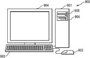
- the figure which shows an example of the display in the embodiment The schematic diagram which shows an example of the external appearance of the computer system in each said embodiment
- Embodiment 1 A numerical value input device according to Embodiment 1 of the present invention will be described with reference to the drawings.
- the numerical input device according to the present embodiment inputs two variables.
- FIG. 1 is a block diagram showing a configuration of a numerical input device 1 according to the present embodiment.
- the numerical value input device 1 according to the present embodiment includes an image data storage unit 11, an image generation unit 12, an image display unit 13, an instruction reception unit 14, a numerical value acquisition unit 15, an output unit 16, and a numerical value storage unit. 17 and a calculation unit 18.
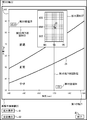
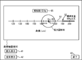
- the coordinate plane image data is image data of a coordinate plane having a first axis 21 and a second axis 22, for example, as shown in FIG.
- the numerical value input device 1 inputs a first variable corresponding to the first axis 21 and a second variable corresponding to the second axis 22.
- FIG. 5 shows a case where the first and second axes 21 and 22 are straight lines on the coordinate plane and the orthogonal coordinate system is orthogonal to each other, but this need not be the case.
- an oblique coordinate system may be used.
- the coordinate plane image data may be any data as long as it can display an image in the plane coordinate system as a result.
- the coordinate plane image data may be an image itself such as raster data, and is rasterized as vector data. It may be data that becomes an image.
- the first axis 21 is an axis indicating the height (cm) which is a variable.
- the second axis 22 is an axis indicating weight (kg) as a variable. Further, the second axis 22 is orthogonal to the first axis.
- the height is taken on the horizontal axis and the weight is taken on the vertical axis, but it goes without saying that it may be reversed. Further, as shown in FIG.
- information indicating that the variable indicated by the axis is height for example, a character string of “height” may be displayed near the first axis 21. .
- the scale and the numerical value may be displayed on the first axis 21 as shown in FIG. The same applies to the second axis 22, even if information indicating that the variable indicated by the axis is weight is displayed in the vicinity of the second axis 22, for example, a character string “weight” is displayed. Good.
- a scale and a numerical value may be displayed on the second axis 22.
- the first region boundary line 23 is a parabola that indicates the relationship between height and weight when the BMI is the first value.
- the second region boundary line 24 is a parabola showing the relationship between height and weight when the BMI is a second value.
- BMI weight (kg) / ⁇ height (m) ⁇ 2
- the coordinate plane is a predetermined function having the values of the first axis 21 and the value of the second axis 22 as arguments (in the present embodiment, the BMI function described above). ) May be divided into a plurality of regions according to the value of. Dividing into a plurality of areas according to the value of the calculation result of the predetermined function means that the area is divided into a plurality of areas for each range of values of the calculation result of the predetermined function as shown in FIG. It may be.
- the coordinate plane is divided into three regions by the first and second region boundary lines 23 and 24. That is, a region delimited by the second axis 22 and the first region boundary line 23 (this region will be referred to as “first region”), the second axis 22, and the first region A region delimited by a boundary line 23 and a second region boundary line 24 (this region will be referred to as a “second region”), a first axis 21, a second axis 22, The region is divided into two regions (hereinafter, this region is referred to as a “third region”).
- first region boundary line 23 is a region boundary line having a BMI of 25
- second region boundary line 24 is a region boundary line having a BMI of 18.5. Is a region where BMI is larger than 18.5 and smaller than 25, and the third region is a region where BMI is smaller than 18.5.
- each region may be easily visually distinguished by coloring the first to third regions with different colors or using different shades. .
- the first region is an “obese” region.
- the second region is a “normal” region because the BMI is larger than 18.5 and smaller than 25.
- the third region is a “slim” region. As shown in FIG. 5, the words “obesity”, “normal”, and “loss” characterizing each region may be displayed for each region.
- coordinate plane image data may be stored in the image data storage unit 11 via a recording medium, and coordinate plane image data transmitted via a communication line or the like is stored in the image data storage unit 11.
- coordinate plane image data input via an input device may be stored in the image data storage unit 11.
- Storage in the image data storage unit 11 may be temporary storage in a RAM or the like, or may be long-term storage.
- the image data storage unit 11 can be realized by a predetermined recording medium (for example, a semiconductor memory, a magnetic disk, an optical disk, etc.).
- the image generation unit 12 includes point graphic image data, enlarged graphic image data, first numerical image data, second numerical image data, function calculation result image data, and first drop line graphic image data. Second drop line graphic image data is generated. These data will be described with reference to FIGS.
- the point graphic image data is image data of the point graphic 31.
- the point graphic 31 is a graphic indicating the position on the coordinate plane of the coordinate plane image 20 indicated by the coordinate plane image data. By designating the position of the point graphic 31, both the value (height) of the first axis 21 and the value (weight) of the second axis 22 corresponding to the point graphic 31 are designated collectively. Will be able to.
- the point graphic 31 is displayed on the coordinate plane image 20, and it can be determined whether or not the person is obese by seeing in which region the point graphic 31 exists. As shown in FIG. 5, the point graphic 31 may be a point graphic (round graphic), or other graphic such as a cross, triangle, or square.
- the image generating unit 12 when the instruction receiving unit 14 described later receives an instruction to specify the position of the point graphic 31, the image generating unit 12 generates point graphic image data corresponding to the position specified by the instruction. That is, the image generation unit 12 generates the point graphic image data so that the point graphic 31 is moved to the position specified by the instruction received by the instruction reception unit 14 described later. Therefore, when the instruction receiving unit 14 (to be described later) receives an instruction to specify the position of the point graphic, the point graphic image data corresponding to the point graphic 31 that has been displayed so far is erased and newly specified. Point graphic image data corresponding to the position may be generated.
- the point graphic image data is image data of a point graphic, and may be an image itself such as raster data as long as the image data can finally display a point graphic. Data that becomes an image by being rasterized as shown in FIG.
- the point graphic image data may be generated on the coordinate plane image 20 indicated by the coordinate plane image data, or may be generated separately from the coordinate plane image 20. In the latter case, the point graphic image data preferably has information indicating the display position on the coordinate plane image 20.
- the point graphic image data may be temporarily stored in a recording medium (not shown), or may be temporarily stored in the image data storage unit 11. What is described in this paragraph is the same for other graphic data generated by the image generation unit 12.
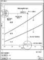
- the enlarged graphic image data is image data of the enlarged graphic 37.
- the enlarged figure 37 is a part of the coordinate plane, and is an enlarged figure of the area including the position of the point graphic 31.
- the user can input numerical values more finely than directly inputting numerical values on the coordinate plane. Therefore, as shown in FIG. 6, in each of the axes corresponding to the first and second axes 21 and 22 in the enlarged graphic 37, finer numerical values are displayed than the first and second axes 21 and 22. Will be.
- the enlarged graphic 37 may be displayed, for example, at the position of the point graphic 31 (for example, the position directly above the point graphic 31) or not. In the latter case, the enlarged graphic 37 may be displayed at a predetermined position (not necessarily on the coordinate plane image 20).
- the image generation unit 12 may generate the point graphic image data so that the point graphic 31 is displayed on the most front side.
- the first numerical image data is first numerical image data.
- the first numerical value is a value of the first axis 21 corresponding to the position of the point graphic 31 acquired by the numerical value acquisition unit 15 described later.
- this 1st numerical value 34 may be displayed in the vicinity of the position of the 1st axis
- the display position of the first numerical value 34 can be moved in accordance with the movement of the point graphic 31.
- the first numerical value 34 may always be displayed at a predetermined position.
- the first numerical image data is usually image data indicating numerical text.
- the second numerical image data is second numerical image data.
- the second numerical value 35 is a value of the second axis 22 corresponding to the position of the point graphic 31 acquired by the numerical value acquisition unit 15 described later. By displaying the second numerical value 35, the user can know the value of the second axis 22 input by the point graphic 31.
- the second numerical value 35 is the same as the first numerical value 34 described above except that the numerical value to be displayed is different, and detailed description thereof is omitted.
- the function calculation result image data is image data of a calculation result value of a predetermined function calculated by the calculation unit 18 described later.
- the user can know the value of the function calculation result corresponding to the values of the first and second axes 21 and 22 input by the point graphic 31. More specifically, for example, the BMI value corresponding to the height and weight input by the point graphic 31 can be known.
- the position where the value 36 of the function calculation result is displayed is not limited. For example, as shown in FIG. 5, it may be near the point graphic 31 or may be a predetermined position. .
- the function calculation result image data is usually image data indicating numerical text.
- the first drop line graphic image data is image data of the first drop line graphic 32.
- the first drop line graphic 32 is a graphic of a drop line (drop line) drawn from the point graphic 31 to the position of the first axis 21 corresponding to the point graphic 31.
- the value of the first axis 21 corresponding to the position of the point graphic 31 can be easily known by the intersection of the first drop line graphic 32 and the first axis 21.
- the second drop line graphic image data is image data of the second drop line graphic 33.
- the second drop line graphic 33 is a drop line graphic drawn from the point graphic 31 to the position of the second axis 22 corresponding to the point graphic 31.
- the value of the second axis 22 corresponding to the position of the point graphic 31 can be easily known by the intersection of the second drop line graphic 33 and the second axis 22.
- the first and second drop line figures 32 and 33 are usually drawn from the point figure 31 in parallel to the first and second axes 21 and 22, but as a result, correspond to the point figure 31. If the value of the 1st and 2nd axis
- the first and second drop line figures 32 and 33 are usually linear figures.
- the image generation unit 12 may generate the original graphic data stored in advance on a recording medium (not shown).
- the original image data may be, for example, image data of a graphic used as a point graphic (for example, a circular graphic), and may be an image such as a frame or grid line used when generating enlarged graphic image data. It may be data, may be image data of a frame used when generating first and second numerical image data and function calculation result image data, or other image data.
- the image display unit 13 displays the coordinate plane image data read from the image data storage unit 11 and each image data such as the point graphic image data generated by the image generation unit 12. It is assumed that the image display unit 13 performs display output for finally performing image display related to coordinate plane image data and the like. Therefore, the image display unit 13 may be, for example, a transmission unit that transmits image data or the like to a display device (for example, a CRT or a liquid crystal display). Further, the image display unit 13 may or may not include a display device that performs the display. The image display unit 13 may be realized by hardware, or may be realized by software such as a driver that drives a display device.
- the image generation unit 12 may sequentially store the generated image data in a recording medium from which the image display unit 13 described later reads the image data.
- the image display unit 13 can display the image data only by reading and displaying the image data from the recording medium. It becomes like this.
- the recording medium may be the image data storage unit 11.
- the instruction receiving unit 14 receives an instruction for designating the position of the point graphic displayed by the image display unit 13.
- an instruction regarding the position of the point graphic 31 on the coordinate plane may be received with a mouse, a trackpad, a touch panel, an arrow key, or the like.
- the instruction regarding the position of the point graphic 31 may be, for example, an instruction for determining the position of the point graphic 31 (for example, clicking on the position of the point graphic 31), or the position of the point graphic 31 is moved. It may be an instruction (for example, dragging a point graphic 31 displayed in advance).
- the instruction receiving unit 14 may receive an instruction as to whether or not to display the enlarged graphic image data. That is, for example, the instruction receiving unit 14 may receive an instruction to display enlarged graphic image data or an instruction to display no enlarged graphic image data.
- the image generation unit 12 may or may not generate the enlarged graphic image data in response to an instruction on whether or not to display the enlarged graphic image data, or the image display unit 13 may generate the enlarged graphic image data.
- Image data may be displayed or not displayed. That is, the process is not limited as long as the display is performed in accordance with the instruction on whether to display the enlarged graphic image data.
- the instruction receiving unit 14 may receive information input from an input device (for example, a keyboard, a mouse, a touch panel, etc.), or may receive information transmitted via a wired or wireless communication line. .
- the instruction receiving unit 14 may or may not include a device (for example, a modem or a network card) for receiving.
- the instruction receiving unit 14 may be realized by hardware, or may be realized by software such as a driver that drives a predetermined device.
- the numerical value acquisition unit 15 acquires a first numerical value that is the value of the first axis 21 corresponding to the position of the point graphic 31 on the coordinate plane and a second numerical value that is the value of the second axis 22.
- the value of the axis corresponding to the position of the point graphic 31 is, for example, in the case of the first axis 21, a straight line is drawn parallel to the second axis 22 from the point graphic 31, and the straight line and the first axis 21. It may be a value corresponding to the intersection with. Similarly, in the case of the second axis 22, it may be a value corresponding to the intersection of the straight line and the second axis 22 by drawing a straight line from the point graphic 31 in parallel to the first axis 21.
- the numerical value acquisition unit 15 may acquire the first and second numerical values by detecting the position of the point graphic 31 on the display screen and converting the position into a position on the coordinate plane. In this case, the numerical value acquisition unit 15 determines the position of the point graphic 31 on the display screen according to whether the point graphic 31 exists on the enlarged graphic 37 or on the coordinate plane. The method of converting to a numerical value of 2 may or may not be changed. That is, if the point graphic 31 exists on the enlarged graphic 37, the first and second numerical values are acquired using the coordinates of the enlarged graphic 37, and if the point graphic 31 exists on the coordinate plane. The first and second numerical values may or may not be acquired using the coordinates of the coordinate plane.
- the output unit 16 outputs the first and second numerical values acquired by the numerical value acquiring unit 15.
- the output may be, for example, display on a display device (for example, a CRT or a liquid crystal display), transmission via a communication line to a predetermined device, printing by a printer, or audio output by a speaker. Alternatively, it may be stored in a recording medium or delivered to another component.
- the output unit 16 may or may not include an output device (for example, a display device or a printer).
- the output unit 16 may be realized by hardware, or may be realized by software such as a driver that drives these devices.
- the numerical value storage unit 17 stores the first and second numerical values accumulated by the output unit 16 as described above. Storage in the numerical value storage unit 17 may be temporary storage in a RAM or the like, or may be long-term storage.
- the numerical value storage unit 17 can be realized by a predetermined recording medium (for example, a semiconductor memory, a magnetic disk, an optical disk, etc.).
- the calculation unit 18 calculates a value of a calculation result of a predetermined function using the first and second numerical values acquired by the numerical value acquisition unit 15 as arguments.
- This predetermined function is preferably the same as the predetermined function used when the coordinate plane is divided into a plurality of regions, but this need not be the case.
- the former case that is, a case where the predetermined function is a BMI equation will be described.
- the predetermined function is stored in a recording medium (not shown), and the calculation unit 18 may calculate the value of the function calculation result from the first and second numerical values by reading the predetermined function. Good.
- the image data storage unit 11 and the numerical value storage unit 17 may be realized by the same recording medium or may be realized by separate recording media.
- the area storing the coordinate plane image data is the image data storage unit 11
- the area storing the first and second numerical values is the numerical value storage unit 17.
- Step S101 The image display unit 13 determines whether to display coordinate plane image data or the like. If so, the process proceeds to step S102. If not, the process of step S101 is repeated until it is determined to be displayed.
- the image display unit 13 may determine to output the coordinate plane image data or the like when receiving an instruction to display the coordinate plane image data or the like, for example, or may display the coordinate plane image data or the like at other timing. May be determined to be displayed.
- Step S102 The image display unit 13 displays the coordinate plane image data read from the image data storage unit 11 and the image data generated by the image generation unit 12.
- coordinate plane image data or the like When coordinate plane image data or the like is displayed for the first time, the point graphic 31 at a predetermined position, the first and second drop line graphics 32 and 33, and the first and second numerical values corresponding thereto. 34, 35, the value 36 of the function calculation result, etc. may be displayed, or they may not be displayed.
- Step S103 The instruction receiving unit 14 determines whether an instruction for specifying the position of the point graphic 31 has been received. If accepted, the process proceeds to step S104, and if not, the process proceeds to step S109.
- Step S104 The image generation unit 12 generates image data such as a point graphic in accordance with the received instruction. Details of this processing will be described later with reference to the flowchart of FIG.
- the numerical value acquisition unit 15 acquires first and second numerical values corresponding to the position of the point graphic 31.
- the numerical value acquisition unit 15 acquires the coordinate value of the screen coordinate corresponding to the position of the point graphic 31.
- the acquisition of the coordinate value may be performed by, for example, an operation system (OS).
- OS operation system
- the screen coordinates are a coordinate system in which the upper left end point of the display screen on which the coordinate plane image 20 or the like is displayed is the origin, the X axis is the right direction, and the Y axis is the lower direction. Further, for example, with the upper left end point of the coordinate system shown in FIG.
- the client coordinates that are the coordinate system are set.
- the numerical value acquisition unit 15 converts the acquired coordinate value of the screen coordinate into the coordinate value of the client coordinate.
- the numerical value acquisition unit 15 acquires the first numerical value (height value) and the second numerical value (weight value) by converting the client coordinates into (height, weight) coordinate values. can do.
- the conversion from the coordinate value of the screen coordinate to the coordinate value of the client coordinate is already known, and a detailed description thereof will be omitted.
- Step S106 The output unit 16 outputs the first and second numerical values acquired by the numerical value acquiring unit 15. In other words, the output unit 16 accumulates the first and second numerical values in the numerical value storage unit 17.
- Step S107 The calculation unit 18 calculates a value of a calculation result of a predetermined function using the first and second numerical values acquired by the numerical value acquisition unit 15.
- Step S108 The image generation unit 12 generates image data or the like of the value 36 of the function calculation result. Details of this processing will be described later with reference to the flowchart of FIG. Then, the process returns to step S102.
- Step S109 The instruction receiving unit 14 determines whether an instruction related to display or non-display of the enlarged graphic 37 has been received. And when it receives, it progresses to step S110, and when that is not right, it progresses to step S113.
- Step S110 The image generation unit 12 determines whether the instruction regarding the enlarged graphic 37 received by the instruction receiving unit 14 is an instruction to display the enlarged graphic 37. If the instruction is to display the enlarged graphic 37, the process proceeds to step S111. If not, that is, if the instruction is to delete the enlarged graphic 37, the process proceeds to step S112.
- Step S111 The image generation unit 12 newly generates image data of the enlarged graphic 37. Then, the process returns to step S102. As a result, the enlarged graphic 37 is displayed.
- Step S112 The image generation unit 12 erases the enlarged figure 37 that has been displayed so far. Then, the process returns to step S102. As a result, the enlarged graphic 37 that has been displayed until then is deleted.
- Step S113 The image display unit 13 determines whether or not to finish displaying the coordinate plane image data and the like. If the process is to end, the process returns to step S101; otherwise, the process returns to step S103. Note that the image display unit 13 may determine to end the display of the coordinate plane image data or the like when receiving an instruction to end the display of the coordinate plane image data or the like. When a predetermined time has elapsed since the last display, the display of the coordinate plane image data and the like may be determined to end. In the flowchart of FIG. 2, the process is terminated by powering off or a process termination interrupt.
- FIG. 3 is a flowchart showing details of the process of generating a point graphic or the like (step S104) in the flowchart of FIG.
- the image generation unit 12 generates point graphic image data in response to an instruction specifying the position of the point graphic 31 received by the instruction receiving unit 14. For example, when the received instruction is an instruction to move the point graphic 31, the image generation unit 12 deletes the point graphic image data at that time, and moves the point graphic image data to the position of the movement destination. Is generated. For example, when the received instruction is an instruction to newly display the point graphic 31, the image generation unit 12 generates the point graphic image data at the designated position.
- the point graphic image data may be generated using, for example, the point graphic 31 stored in advance on a recording medium (not shown).
- the generation of the point graphic image data may be, for example, a process for determining the display position of the point graphic 31.
- Step S202 The image generation unit 12 performs first and second image data of first and second drop line graphics 32 and 33 extending from the point graphic 31 to the first and second axes 21 and 22, respectively.
- Dropline graphic image data is generated.
- the X-axis value of the screen coordinate corresponding to the point graphic 31 is A
- the Y-axis value is B
- the first axis 21 exists on a straight line where the Y-axis of the screen coordinate is C.
- the image generation unit 12 performs the first drop that is a line segment from (A, B) to (A, C).
- First drop line graphic image data for displaying the line graphic 32 may be generated.
- the image generator 12 generates second drop line graphic image data for displaying the second drop line graphic 33 that is a line segment from (A, B) to (D, B). Also good. Note that client coordinates may be used instead of screen coordinates. And it returns to the flowchart of FIG.
- FIG. 4 is a flowchart showing details of processing for generating a function image or the like (step S108) in the flowchart of FIG.
- the image generation unit 12 generates first numerical image data and second numerical image data using the first and second numerical values acquired by the numerical value acquisition unit 15.
- the image generation unit 12 reads, for example, original image data that is graphic image data such as a frame stored in advance on a recording medium (not shown), and the first numerical value or the second numerical text is added to the image data. By inserting, the first and second numerical image data may be generated.
- the display positions of the first and second numerical values 34 and 35 are set so as to be in the vicinity of the first numerical value of the first axis 21 and in the vicinity of the second numerical value of the second axis 22, respectively. Also good. In this case, the display positions of the first and second numerical values 34 and 35 may be determined by performing conversion from the coordinate system of the first and second axes 21 and 22 to client coordinates.
- Step S302 The image generation unit 12 generates function calculation result image data using the value of the calculation result of the function calculated by the calculation unit 18.
- the image generation unit 12 reads, for example, original image data that is graphic image data such as a frame stored in a recording medium (not shown) in advance, and inserts a text of a value of a function calculation result into the image data.
- the function calculation result image data may be generated by The display position of the function calculation result value 36 may be set so as to be in the vicinity of the point graphic 31.
- Step S303 The image generation unit 12 determines whether or not the enlarged graphic 37 is being displayed. That is, it is determined whether or not the enlarged graphic image data is included in the image to be displayed by the image display unit 13. If the enlarged graphic 37 is being displayed, the process proceeds to step S304, and if not, the process returns to the flowchart of FIG.
- the image generation unit 12 generates enlarged graphic image data that is image data of the enlarged graphic 37.
- the image generation unit 12 reads, for example, original image data that is image data such as a frame graphic stored in advance on a recording medium (not shown), and a predetermined position (for example, a center point) of the image data is read out.
- Image data such as broken grid lines and coordinate values is generated so as to be coordinate values of the point graphic 31 (this is the coordinate values of the first and second axes 21 and 22).
- the image generation unit 12 reads image data of a graphic such as a frame and arranges image data of broken grid lines in the frame according to the coordinate value of the point graphic 31.
- the image data of the broken grid lines is arranged so that the position of the point graphic 31 is the intersection of the grid lines, and the point If any of the coordinate values of the graphic 31 is not an integer, the image data of broken grid lines is arranged by shifting by that amount.
- the number after the decimal point of the coordinates in the direction of the first axis 21 is A and the grid lines are provided in integer units of the value of the first axis 21, the intersection of the grid lines is the first
- the grid line may be set so that the value of the first axis 21 is shifted by A / 10, which is one unit of the grid line in the direction of the axis 21.
- the image generation unit 12 uses the unit length of the grid line and the coordinate value of the point graphic 31 so that the grid line included in the enlarged graphic image data has an integer, every “5”, or A line corresponding to the value of the first axis 21 every “10” can be specified. Then, the image generation unit 12 may arrange image data of text having coordinate values in association with the specified line.
- the coordinate value of the point figure 31 can be known from the first and second numerical values acquired by the numerical value acquiring unit 15, for example.
- the image generating unit 12 is configured so that the location of the point graphic 31 on the enlarged graphic 37 becomes the location of the point graphic 31 on the coordinate plane constituted by the first and second axes 21 and 22. The display position of 37 may be determined. And it returns to the flowchart of FIG.
- step S111 the generation of the enlarged graphic image data in the above-described step S111 is performed in the same manner as described in step S304. Further, in the flowchart of FIG. 4, the order of processing in step S301, step S302, and steps S303 and S304 does not matter.
- the image display unit 13 displays each image data on a display.
- the user inputs an instruction to output the coordinate plane image 20 to the numerical input device 1 by operating a mouse or a keyboard.
- the image display unit 13 determines that it is time to display the image data (step S101), reads the coordinate plane image data from the image data storage unit 11, and outputs it to the display (step S102).
- the coordinate plane image 20 shown in FIG. 5 includes a point graphic 31, first and second drop line graphics 32, 33, first and second numerical values 34, 35, and a function calculation result value 36. A screen without the display of is displayed on the display.
- step S104 the image generation unit 12 performs processing for generating a point graphic or the like. Specifically, the image generation unit 12 generates point graphic image data at the position clicked with the mouse (step S201). Here, it is assumed that the position where the height value is “170 (cm)” and the weight value is “85.0 (kg)” is clicked.
- the image generation unit 12 also includes first and second image data of first and second drop line graphics 32 and 33 extending perpendicularly from the point graphic 31 to the first and second axes 21 and 22, respectively. Dropline graphic image data is generated (step S202).
- the numerical value acquisition unit 15 acquires the first numerical value “170” and the second numerical value “85.0” corresponding to the point graphic 31 on the coordinate plane (step S105).
- the first and second numerical values are accumulated in the numerical value storage unit 17 by the output unit 16 (step S106).
- the calculation unit 18 calculates the value of the calculation result of the predetermined function, that is, the BMI value (step S107).
- the BMI value is “29.4”.
- the image generation unit 12 performs processing for generating function calculation result image data and the like (step S108). Specifically, the image generation unit 12 generates first and second numerical image data corresponding to the first and second numerical values acquired by the numerical value acquisition unit 15 (step S301). Further, the image generation unit 12 generates function calculation result image data corresponding to the BMI value calculated by the calculation unit 18 (step S302). Here, since the enlarged graphic 37 is not displayed, the process of generating the enlarged graphic image data is not performed (step S303).
- the image display unit 13 displays image data such as the point graphic 31 generated by the image generation unit 12 on the display (step S102). As a result, the display shown in FIG. 5 is performed.
- the instruction receiving unit 14 receives an instruction to display the enlarged graphic 37 (step S109).
- the instruction receiving unit 14 uses the information that associates the position of the “enlarged display” button 41 and the type of the button 41 stored in a recording medium (not shown) to position the “enlarged display” button 41. When is clicked, it may be detected that the “enlarged display” button 41 is clicked. The same applies to the other buttons.
- the image generation unit 12 determines that the instruction is to display the enlarged graphic 37 (step S110), and generates enlarged graphic image data corresponding to the position of the point graphic 31 shown in FIG. 5 (step S111). ). Then, the enlarged graphic 37 is displayed on the display as shown in FIG. 6 (step S102). In the enlarged graphic 37, since the periphery of the position of the point graphic 31 is enlarged, the user can position the point graphic 31 in more detail. As a result, more detailed numerical input can be realized.
- the position of the point graphic 31 is not the position intended by the user, for example, the height value is “174 (cm)” and the weight value is “86.6 (kg)”.
- the user moves the point graphic 31 by dragging the point graphic 31 with a mouse or the like in the display of FIG. 6 or by clicking a point on a new target coordinate plane.
- the image generation unit 12 generates point graphic image data and first and second drop line graphic image data at the moved position (steps S103 and S104).
- the numerical value acquisition unit 15 acquires first and second numerical values corresponding to the position of the point graphic 31 (step S105).
- the first and second numerical values are accumulated in the numerical value storage unit 17 by the output unit 16 (step S106). Further, the calculation unit 18 calculates a BMI value using the acquired first and second numerical values (step S107). Then, the image generation unit 12 generates first and second numerical image data, function calculation result image data, and enlarged graphic image data displayed at the position of the point graphic 31 after movement (step S108, They are displayed on the display (step S102).
- the point graphic 31 is moved at a stretch has been described, but this need not be the case.
- a trajectory in the middle of the user dragging the point graphic 31 may be sequentially displayed by the image display unit 13. As described above, the point graphic 31 may be moved by repeating the processes of steps S102 to S108.
- the image generation unit 12 generates enlarged graphic image data in which the display position is changed according to the position of the point graphic 31.
- the point graphic 31 is always displayed at the center of the enlarged graphic 37.
- the height and weight values on the enlarged graphic 37 indicated by the point graphic 31 and the first and second axes 21 are displayed.
- step S105 the numerical value acquisition unit 15 sets the client coordinates on the coordinate plane formed by the first and second axes 21 and 22 as the client coordinates. It is only necessary to obtain the first and second numerical values.
- the first and second numerical values corresponding to the position of the point graphic 31 on the enlarged graphic 37 are set according to the first and second numerical values.
- step S105 processing in the flowchart of FIG. 2
- the acquisition method differs depending on whether or not the enlarged graphic is displayed. That is, it is necessary to obtain the first and second numerical values as in the flowchart of FIG.
- the flowchart of FIG. 9 will be described.
- Step S401 The numerical value acquisition unit 15 determines whether or not the enlarged graphic 37 is displayed. And when it is displayed, it progresses to step S402, and when that is not right, it progresses to step S403.
- Step S402 The numerical value acquisition unit 15 acquires the first and second numerical values using the coordinate system of the enlarged figure 37. Therefore, in this case, the coordinate system of the enlarged figure 37 is used as the client coordinates, and the conversion from the screen coordinates to the client coordinates, the processing of converting the coordinate values of the client coordinates into the height and weight values, and the like are performed. And it returns to the flowchart of FIG.
- Step S403 The numerical value acquisition unit 15 acquires the first and second numerical values in the same manner as described in step S105, and returns to the flowchart of FIG.
- the processes of steps S303 and S304 in the flowchart of FIG. 4 do not have to be performed.
- the enlarged graphic 37 may be newly generated or not. In the former case, for example, a new centered on the position on the coordinate plane constituted by the first and second axes 21 and 22 corresponding to the position of the enlarged figure 37 where the point figure 31 was present last.
- the image generation unit 12 may generate enlarged graphic image data so that the enlarged graphic 37 is displayed.
- step S109, S110, S112, S102 When the user clicks the “overall display” button 42 in the display of FIG. 6, the enlarged graphic image data is erased accordingly, and the enlarged graphic 37 is not displayed as shown in FIG. 5 (step S109, S110, S112, S102). Further, when the user clicks the “end” button 43 in the display of FIG. 5, the display of the coordinate plane image 20 and the like is ended accordingly and is not displayed on the display (step S113).
- the height and weight values input as in the above specific example may be added to a database corresponding to the input user, or other usage may be performed.
- the numerical value input device 1 it is possible to input the first and second numerical values using the GUI on the coordinate plane without using a numeric keypad.
- a numeric keypad For example, when inputting numerical values in a browser, etc., there is an advantage that numerical values can be input by operating only the pointing device without using both a pointing device and a keyboard such as a numeric keypad. is there.
- by displaying the enlarged graphic 37 it becomes possible to easily input fine numerical values. Further, as shown in FIG.
- the coordinate plane is divided into a plurality of regions by the first and second region boundary lines 23 and 24, so that the value of the calculation result of the function corresponding to the input value is obtained.
- Attributes for example, “obesity”, “normal”, “loss”, etc.
- the first and second numerical values 34 and 35 it is possible to easily know the input accurate values.
- the function calculation result value 36 it is possible to easily know the value of the function calculation result corresponding to the input numerical value.
- the first and second drop line graphics 32 and 33 the positions of the first and second axes 21 and 22 corresponding to the position of the point graphic 31 can be easily specified. It becomes like this.
- the enlarged graphic 37 is a partial area of the coordinate plane, an outline of the position of the point graphic 37 with respect to the entire coordinate plane is displayed even when the enlarged graphic 37 is displayed. There is also an advantage that can be easily grasped.
- the enlargement ratio of the enlarged figure 37 may be changeable.
- the enlargement ratio may be increased or decreased by the enlargement ratio changing slider 44.
- the enlarged graphic 37 can be displayed at the user's preferred magnification.
- the image data of a plurality of enlarged figures corresponding to the enlargement ratio may be stored in advance in a recording medium (not shown), or the image data of the original enlarged figure is used to correspond to the enlargement ratio. You may make it produce
- the numerical value acquisition unit 15 acquires the first and second numerical values according to the magnification ratio of the enlarged graphic 37.
- the client coordinates are changed according to the enlargement ratio of the enlarged figure 37, and the numerical value acquisition unit 15 acquires the first and second numerical values using the coordinate values of the client coordinates after the change.
- the client coordinates themselves are not changed, and the correspondence between the client coordinates and the coordinates in the enlarged figure 37 may be changed. It is assumed that the enlargement ratio of the enlarged figure can be changed in the following embodiments.
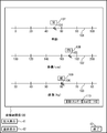
- the case where the enlarged graphic 37 in which the position of the point graphic 31 is enlarged has been described. However, as shown in FIG. 11, it is a part of the first and second axes 21 and 22. Then, numerical values may be input using the first and second enlarged figures 38 and 39 in which the area including the position corresponding to the point figure 31 is enlarged. In this case, the first and second enlarged figures 38 and 39 may be displayed at all times. That is, in the flowchart of FIG. 2, the processing of steps S109 to S112 need not be performed. Further, in the flowchart of FIG. 4, the process of step S304 may always be performed. That is, the process of step S303 may be deleted and the process may proceed from step S302 to step S304.
- the method for generating the first and second enlarged graphic image data for displaying the first and second enlarged graphics 38 and 39 is the same as the method for generating the enlarged graphic image data, and a detailed description thereof is provided. Is omitted.
- the first and second enlarged graphic 38, 39 may move according to the movement of the point graphic 31, or may not move. In the latter case, as shown in FIG. 12, the first falling line figure 32 may be shifted at the boundary of the enlarged figure.
- the numerical value input apparatus 1 also includes the image data storage unit 11, the image generation unit 12, the image display unit 13, the instruction reception unit 14, the numerical value acquisition unit 15, the output unit 16, and the numerical value.
- a storage unit 17 and a calculation unit 18 are provided.
- coordinate axis image data is also stored in addition to the coordinate plane image data.
- the coordinate plane image data is image data of a coordinate plane having a first axis and a second axis as described above.
- the coordinate axis image data is image data of the coordinate axis of the third axis.
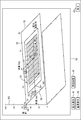
- the coordinate plane image data and the coordinate axis image data may constitute a coordinate system in a three-dimensional space, or may not be so. In the present embodiment, the former case will be described. Therefore, for example, the coordinate plane image data and the coordinate axis image data form a coordinate space having the first axis 51, the second axis 52, and the third axis 53, as shown in FIG.
- the numerical input device 1 has a first variable corresponding to the first axis 51, a second variable corresponding to the second axis 52, and a third variable corresponding to the third axis 53. Input with the variable. However, in the present embodiment, first, the third variable corresponding to the third axis 53 is input, and then the first and second variables corresponding to the first and second axes 51 and 52 are input. Shall be entered. In FIG.
- the first to third axes 51 to 53 are straight lines and are orthogonal coordinate systems in which they are orthogonal (however, a three-dimensional orthogonal coordinate system is converted into a two-dimensional plane
- a three-dimensional orthogonal coordinate system is converted into a two-dimensional plane
- an oblique coordinate system may be used.
- the first axis 51 is an axis indicating a variable height (cm)
- the second axis 52 is an axis indicating a variable body weight (kg)
- the third axis 53 is a variable. It is an axis indicating the age.
- any axis may be assigned to any variable.
- the names of variables indicated by the axes may be displayed near each axis, and a scale and a numerical value may be displayed on each axis.
- the formula indicating the basic energy amount is known as the Harris-Benedict formula and is as follows (however, it is a formula for men).
- Basic energy (kcal / day) 66.47 + 13.75 x body weight (kg) + 5.003 x height (cm) -6.775 x age
- the basic energy amount having a constant value is a plane in a coordinate system with height, weight, and age as three axes. Therefore, for example, on the coordinate space shown in FIG. 15, the relationship between height, weight, and age when the basic energy amount is a certain value (this value is referred to as “boundary value”) is shown.
- a region boundary surface that is a plane may be displayed or may not be displayed. In the present embodiment, the latter case will be described.
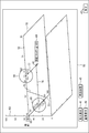
- the coordinate plane image data is a predetermined function (in this embodiment, the above Harris / Harris) with the values of the first axis 51, the second axis 52, and the third axis 53 as arguments. Benedict's equation), and coordinates that are divided into a plurality of regions according to the value of the calculation result of the function obtained by substituting the third numerical value acquired by the numerical value acquisition unit 15 described later for the value of the third axis 53
- It may be plane image data.
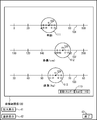
- the coordinate plane is divided into two regions by the intersection line between the coordinate plane of the coordinate plane image data and the region boundary surface.
- the boundary value is “1200 (kcal / day)”.
- this value may be another appropriate value.
- the coordinate plane is divided into two regions by a region boundary line 78. That is, a region where the basic energy amount is greater than 1200 (kcal / day) (on the right side of the region boundary line 78 in FIG. 16) and a region smaller than 1200 (kcal / day) (the left side of the region boundary line 78 in FIG. 16). And divided. Each region may be visually distinguished easily by coloring with a different color or with different shading.
- the wording “basic energy amount: large” characterizing the region may be displayed, and a region where the basic energy amount is smaller than 1200 (kcal / day). May display the wording “basic energy amount: small” characterizing the region.
- the image generation unit 12 includes the point graphic image data, the enlarged graphic image data, the first to third numerical image data, the function calculation result image data, and the first and second image data. Dropline graphic image data is generated. These data will be described with reference to FIGS. 15 to 17.
- the point graphic image data is image data of the point graphic 61.
- the point graphic 61 is a graphic indicating the position on the coordinate plane indicated by the coordinate plane image data, the position on the coordinate axis indicated by the coordinate axis image data, and the like.
- the position of the point graphic 61 By specifying the position of the point graphic 61, the value of the third axis 53 corresponding to the point graphic 61 and the values of the first and second axes 51 and 52 can be specified.
- a point graphic for specifying a position on the third axis 53 and the first and second axes 51 and 52 are described.
- Numerical values may be input using two point graphics including a point graphic for specifying a position on a coordinate plane constituted by:
- the description of the other point graphic 61 is the same as the description of the point graphic 31 of the first embodiment, and the description thereof is omitted.
- the enlarged graphic image data is image data of the enlarged graphic 79.
- the enlarged graphic 79 is a partial area of the coordinate plane constituted by the first and second axes 51 and 52 and is an enlarged graphic of the area including the position of the point graphic 61.
- the enlarged graphic 79 is the same as the enlarged graphic 37 of the first embodiment, and a description thereof is omitted.
- the first to third numerical image data are image data of the first to third numerical values 66, 67, and 68, respectively.
- the first to third numerical values are values of the first to third axes 51 to 53 corresponding to the position of the point graphic 61 acquired by the numerical value acquiring unit 15 described later.
- the first to third numerical image data are the same as the first and second numerical image data of the first embodiment, and the description thereof is omitted.
- the first to third numerical values 66 to 68 may be displayed in the vicinity of the positions of the first to third axes 51 to 53 corresponding to the first to third numerical values, for example. May be.
- the function calculation result image data is image data of a value 36 of a predetermined function calculation result calculated by the calculation unit 18 described later.
- This function calculation result image data is the same as the function calculation result image data of the first embodiment, and a description thereof will be omitted.
- the first and second drop line graphic image data are image data of the first and second drop line graphic 76 and 77, respectively.
- the first and second drop line figures 76 and 77 are drop line figures drawn from the point figure 61 to the first and second axes 51 and 52, respectively.
- the first and second falling line graphic image data is the same as the first and second falling line graphic data of the first embodiment, and the description thereof is omitted.
- the image generation unit 12 may generate enlarged graphic image data in which the display position is changed in accordance with the position of the point graphic 61, or the position of the point graphic 61 is within an enlarged area of the enlarged graphic 79. In this case, it is not necessary to change the position of the enlarged graphic 79 as in the first embodiment. In the present embodiment, as in the first embodiment, the former case will be described.
- the image generation unit 12 may generate image data of the region boundary line 78.
- the image generation unit 12 sets a boundary value (1200 kcal / day in the present embodiment) to a value (basic energy amount in the present embodiment) of a predetermined function (in this embodiment, Harris Benedict formula).
- a predetermined function in this embodiment, Harris Benedict formula.
- Substituting and generating image data of the region boundary line 78 by generating image data of the locus on the coordinate plane of the function obtained by substituting the third numerical value acquired by the numerical value acquisition unit 15 for the value of the third axis 53 can do.
- the generated image data of the region boundary line 78 may be added to the coordinate plane image data stored in the image data storage unit 11. Note that the image generation unit 12 may not generate the image data of the region boundary line 78.
- image data of the region boundary line 78 corresponding to various third numerical values is included in the coordinate plane image data stored in the image data storage unit 11 in advance, and the image display unit 13 displays the coordinate plane image.
- the region boundary line 78 may be displayed on the coordinate plane by reading the image data of the region boundary line 78 corresponding to the third numerical value acquired by the numerical value acquisition unit 15.
- the image display unit 13 is the same as that of the first embodiment except that the coordinate axis image data read from the image data storage unit 11 and the third numerical image data are also displayed, and the description thereof is omitted.
- the image display unit 13 may display the coordinate plane image data and the coordinate axis image data so that the first to third axes 51 to 53 form a coordinate space, or display them separately. May be.
- the image display unit 13 determines the third axis 53 in advance.
- the coordinate plane image data may or may not be displayed at the position. In the latter case, for example, the image display unit 13 positions the third axis 53 corresponding to a third numerical value acquired by a numerical value acquisition unit 15 described later (the acquisition of the third numerical value will be described later).
- coordinate plane image data may be displayed.
- the instruction receiving unit 14 may receive an instruction to end the input to the third axis 53 in addition to the same processing as the instruction receiving unit 14 of the first embodiment. This is because in the present embodiment, first, numerical values for the third axis 53 are received, and thereafter, numerical values for the first and second axes 51 and 52 are received.
- the numerical value acquisition unit 15 acquires a third numerical value that is a value of the third axis 53 corresponding to the position of the point graphic 61 and is on a coordinate plane constituted by the first and second axes 51 and 52.
- a first numerical value that is the value of the first axis 51 corresponding to the position of the point graphic 61 and a second numerical value that is the value of the second axis 52 are acquired.
- the method by which the numerical value acquisition unit 15 acquires numerical values is the same as in the first embodiment, and a description thereof is omitted.
- the point graphic 61 may exist on the third axis 53, or may exist on the coordinate space.
- the former case will be described. That is, when inputting the third variable, the image generation unit 12 restricts the movement of the point graphic 61 so that the point graphic 61 can move only on the third axis 53. .
- the image generation unit 12 may generate drop line graphic image data that is graphic data of a drop line with respect to the third axis 53 from the point graphic 61.
- the output unit 16 also outputs the third numerical value acquired by the numerical value acquiring unit 15.
- the rest is the same as in the first embodiment, and the description thereof is omitted.
- the calculation unit 18 calculates a value of a calculation result of a predetermined function using the first to third numerical values acquired by the numerical value acquisition unit 15 as arguments.
- the predetermined function is a Harris Benedict formula for calculating a basic energy amount from height, weight, and age.
- steps S501 to S504 are the same as those in the flowchart of FIG. 2 of the first embodiment except for the above-described differences such as displaying the coordinate axis image data together with the coordinate plane image data. Description is omitted.
- Step S501 The instruction receiving unit 14 determines whether an instruction for specifying the position of the point graphic 61 has been received. If accepted, the process proceeds to step S502, and if not, the process proceeds to step S503. In the present embodiment, as described above, it is assumed that the point graphic 61 is set to be movable only on the third axis 53 when the instruction to the point graphic 61 is received. .
- Step S502 The image generation unit 12 generates image data such as a point graphic in accordance with the received instruction. Details of this processing will be described later with reference to the flowchart of FIG.
- Step S503 The instruction receiving unit 14 determines whether an instruction to end the input to the third axis 53 has been received. If the input to the third shaft 53 is to be terminated, the process proceeds to step S504. If not, the process returns to step S501.
- Step S504 The image display unit 13 displays the coordinate plane image data and coordinate axis data read from the image data storage unit 11 and the image data generated by the image generation unit 12. Note that the image display unit 13 displays the coordinate plane 75 corresponding to the coordinate plane image data at the position of the third axis 53 corresponding to the third numerical value acquired in the processing of steps S501 to S503. . In addition, when the image display unit 13 displays the coordinate plane image data and the like for the first time, the point graphic 61 at a predetermined position, the first and second drop line graphics 76 and 77 corresponding thereto, The first and second numerical values 66 and 67, the value 69 of the function calculation result, and the like may be displayed.
- FIG. 14 is a flowchart showing details of the process of generating a point graphic or the like (step S502) in the flowchart of FIG.
- Step S601 The image generation unit 12 generates point graphic image data in response to an instruction specifying the position of the point graphic 61 received by the instruction receiving unit 14. For example, when the received instruction is an instruction to move the point graphic 61, the image generation unit 12 deletes the point graphic image data at that time, and moves the point graphic image data to the destination position. Is generated. For example, when the received instruction is an instruction to newly display the point graphic 61, the image generation unit 12 generates the point graphic image data at the specified position.
- the point graphic image data may be generated using, for example, a point graphic 61 stored in advance on a recording medium (not shown). The generation of the point graphic image data may be, for example, a process for determining the display position of the point graphic 61.
- the numerical value acquisition unit 15 acquires a third numerical value corresponding to the position of the point graphic 61.
- the numerical value acquisition unit 15 acquires the coordinate value of the screen coordinate corresponding to the position of the point graphic 61.
- the coordinate value of the screen coordinate is converted into the coordinate value of the client coordinate.
- the lower limit value (“0” in FIG. 15) and the upper limit value (“100” in FIG. 15) of the third axis 53 are associated with the coordinate values of the client coordinates corresponding to them. And Therefore, the numerical value acquisition unit 15 can acquire the value of the corresponding third axis 53 from the coordinate value of the client coordinate using the correspondence.
- Step S603 The output unit 16 outputs the third numerical value acquired by the numerical value acquiring unit 15. That is, the output unit 16 accumulates the third numerical value in the numerical value storage unit 17.
- the image generation unit 12 generates the third numerical image data using the third numerical value acquired by the numerical value acquisition unit 15.
- the image generation unit 12 reads, for example, original image data that is graphic image data such as a frame stored in a recording medium (not shown) in advance, and inserts a third numerical text into the image data.
- Third numerical image data may be generated.
- the display position of the third numerical value 68 may be set to be close to the third numerical value of the third axis 53. In this case, the display position of the third numerical value 68 may be determined by performing conversion from the coordinate system of the third axis 53 to client coordinates. And it returns to the flowchart of FIG.
- the image display unit 13 displays each image data on the display.
- the user inputs an instruction to output the coordinate space image 50 to the numerical input device 1 by operating a mouse or a keyboard.
- the image display unit 13 determines that it is time to display the image data (step S101), reads the coordinate plane image data and the coordinate axis image data from the image data storage unit 11, and outputs them to the display (step S102). ).
- the display shown in FIG. 15 is performed. In this display, a screen without displaying the point graphic 61 and the third numerical value 68 is displayed on the display.
- step S501 the instruction receiving unit 14 determines that an instruction for specifying the position of the point graphic 61 has been received.
- the image generation unit 12 or the like performs a process of generating a point graphic or the like (step S502). Specifically, the image generation unit 12 generates point graphic image data on the third axis 53 clicked with the mouse (step S601). Here, it is assumed that a position whose age is “50” is clicked.
- the numerical value acquisition unit 15 acquires a third numerical value “50” corresponding to the point graphic 61 (step S602).
- the third numerical value is accumulated in the numerical value storage unit 17 by the output unit 16 (step S603).
- the image generation unit 12 generates third numerical image data corresponding to the third numerical value acquired by the numerical value acquisition unit 15 (step S604).
- the image display unit 13 displays the image data such as the point graphic 61 generated by the image generation unit 12 on the display (step S102).
- the display shown in FIG. 15 is performed.
- the instruction receiving unit 14 receives an instruction to end the input to the third axis (step S503).
- the image display unit 13 displays the coordinate plane 75 on the display at the position of the third axis 53 corresponding to the third numerical value “50” acquired by the numerical value acquiring unit 15 (step S504).
- the display shown in FIG. 16 is performed.
- a screen without display of the point graphic 61, the first and second drop line graphics 76 and 77, the first and second numerical values 66 and 67, and the function calculation result value 69 is displayed on the display. It will be.
- the axes corresponding to the first and second axes 51 and 52 are displayed at the positions where the first and second axes 51 and 52 are displayed in FIG. The axis may not be displayed.
- step S103 the instruction receiving unit 14 determines that an instruction for specifying the position of the point graphic 61 has been received.
- the image generation unit 12 performs processing for generating a point graphic or the like (step S104). Specifically, the image generation unit 12 generates point graphic image data at the position clicked with the mouse (step S201).
- a position where the height value is “170 (cm)” and the weight value is “60 (kg)” is clicked.
- the image generation unit 12 also includes first and second image data of first and second drop line graphics 76 and 77 extending perpendicularly from the point graphic 61 to the first and second axes 51 and 52, respectively. Dropline graphic image data is generated (step S202).
- the numerical value acquisition unit 15 acquires the first numerical value “170” and the second numerical value “60” corresponding to the point graphic 61 on the coordinate plane 75 (step S105).
- the first and second numerical values are accumulated in the numerical value storage unit 17 by the output unit 16 (step S106).
- the calculation unit 18 calculates the value of the calculation result of the predetermined function, that is, the value of the basic energy amount (step S107). Note that the calculation unit 18 acquires the third numerical value from the numerical value storage unit 17 through a route (not shown) and uses it for the calculation.
- the basic energy amount is “1403 (kcal / day)”.
- the image generation unit 12 performs processing for generating function calculation result image data and the like (step S108). Specifically, the image generation unit 12 generates first and second numerical image data corresponding to the first and second numerical values acquired by the numerical value acquisition unit 15 (step S301). The image generation unit 12 generates function calculation result image data corresponding to the value of the basic energy amount calculated by the calculation unit 18 (step S302). Here, since the enlarged graphic 79 is not displayed, the process of generating the enlarged graphic image data is not performed (step S303).
- the image display unit 13 displays image data such as the point graphic 61 generated by the image generation unit 12 on the display (step S504). As a result, the display shown in FIG. 16 is performed. In the display of FIG. 16, it is assumed that the user clicks the “enlarged display” button 41 displayed on the display by operating the mouse to display the enlarged figure 79. Then, the instruction receiving unit 14 receives an instruction to display the enlarged graphic 79 (step S109). The image generation unit 12 determines that the instruction is to display the enlarged graphic 79 (step S110), and generates enlarged graphic image data corresponding to the position of the point graphic 61 shown in FIG. 16 (step S111). ). Then, the enlarged figure 79 is displayed on the display as shown in FIG. 17 (step S102). In the enlarged graphic 79, since the periphery of the position of the point graphic 61 is enlarged, the user can position the point graphic 61 in more detail. As a result, more detailed numerical input can be realized.
- the first to third numerical values can be input using the GUI on the coordinate space without using the numeric keypad. Also in this case, since the first and second numerical values can be input together, the same effect as in the first embodiment can be obtained.
- the first and second enlarged graphics shown in FIG. Numerical values may be input using 83 and 84.
- the numerical value may be input using the third enlarged graphic 85 shown in FIG.
- a process of generating image data of the third enlarged graphic 85 may be performed at the end of the flowchart of FIG.
- the first to third enlarged figures 83 to 85 may move in accordance with the movement of the point figure 61, and may not move, as in the first embodiment.
- the numerical value input apparatus 1 also includes the image data storage unit 11, the image generation unit 12, the image display unit 13, the instruction reception unit 14, the numerical value acquisition unit 15, the output unit 16, and the numerical value.
- a storage unit 17 and a calculation unit 18 are provided.
- the image data storage unit 11 stores coordinate axis image data.
- the coordinate axis image data is image data of coordinate axes.
- the coordinate axis image data is image data of a coordinate axis that is the first axis 91, as shown in FIG.
- the numerical value input device 1 inputs a first variable corresponding to the first axis 91.
- the first axis 91 is a straight line
- the first axis 91 may be a curve other than a straight line.
- the first axis 91 is an axis indicating the height (cm) which is a variable.
- shaft 91 may be in the vertical direction, and may be in other directions.
- the name of the variable indicated by the axis may be displayed near the first axis 91, and a scale and a numerical value may be displayed on each axis, as in the first embodiment. .
- the standard weight is a function of increasing height. Therefore, for example, a boundary point where the standard weight has a certain value may be indicated on the coordinate axes shown in FIG.
- a boundary point 92 between the thick line and the thin line on the first axis 91 is a boundary point at which the standard weight is 80 (kg). This value may be another appropriate value.
- a thick line area on the first axis 91 is an area where the standard weight is 80 (kg) or more.
- the coordinate axis image data is divided into a plurality of regions in accordance with the value of a predetermined function (standard weight expression in the present embodiment) having the coordinate axis value (height in the present embodiment) as an argument.
- the thickness of the line may be changed for each region, the type of line (for example, solid line, broken line, wavy line, etc.) may be changed, or the color of the line may be changed. May be. In this way, each region can be easily distinguished visually.
- the wording “standard weight 80 kg or more” characterizing the region may be displayed. In FIG. 20, nothing is described in an area where the standard weight is smaller than 80 (kg), but the word “standard weight 80 kg or less” or the like characterizing the area may also be displayed in the area.
- the image generation unit 12 generates point graphic image data, enlarged graphic image data, first numerical image data, and function calculation result image data. These data will be described with reference to FIGS.
- the point graphic image data is image data of the point graphic 93.
- the point graphic 93 is a graphic indicating the position on the coordinate axis indicated by the coordinate axis image data. By designating the position of the point graphic 93, the value of the first axis 91 corresponding to the point graphic 93 can be designated.
- the description of the other point graphic 93 is the same as the description of the point graphic 31 of the first embodiment, and the description thereof is omitted.
- the enlarged graphic image data is image data of the enlarged graphic 96.
- the enlarged graphic 96 is a partial area of the coordinate axis which is the first axis 91 and is an enlarged graphic of the area including the position of the point graphic 93.
- the enlarged graphic 96 is the same as the enlarged graphic 37 of the first embodiment except that it is an enlarged graphic on a one-dimensional axis, and the description thereof is omitted.
- the first numerical image data is image data of the first numerical value 94.
- the first numerical value is a value of the first axis 91 corresponding to the position of the point graphic 93 acquired by the numerical value acquisition unit 15 described later.
- the first numerical image data is the same as the first and second numerical image data of the first embodiment, and a description thereof is omitted.
- the first numerical value 94 may or may not be displayed in the vicinity of the position of the first axis 91 corresponding to the first numerical value, for example.
- the function calculation result image data is image data of a calculation result value of a predetermined function calculated by the calculation unit 18 described later. This function calculation result image data is the same as the function calculation result image data of the first embodiment, and a description thereof will be omitted.
- the point graphic 93 is displayed on the first axis 91, the case where the image generation unit 12 does not generate the falling line graphic image data will be described.
- the point graphic 93 is displayed on the first axis 91.
- the drop line graphic image which is image data of a drop line graphic extending from the point graphic 93 to the position of the value of the first axis 91 corresponding to the position of the point graphic 93
- the data may be generated by the image generation unit 12.
- the image generation unit 12 may generate enlarged graphic image data in which the display position is changed in accordance with the position of the point graphic 93, or the position of the point graphic 93 is within an enlarged area of the enlarged graphic 96. In this case, it is not necessary to change the position of the enlarged figure 96, as in the first embodiment. In the present embodiment, as in the first embodiment, the former case will be described.
- the image display unit 13 is the same as that of the first embodiment except that the coordinate axis image data read from the image data storage unit 11 is displayed, and the description thereof is omitted.
- the numerical value acquisition unit 15 acquires a first numerical value corresponding to the position of the point graphic 93 on the coordinate axis.
- the method by which the numerical value acquisition unit 15 acquires numerical values is the same as in the first embodiment, and a description thereof is omitted.
- the output unit 16 outputs the first numerical value acquired by the numerical value acquiring unit 15.
- the method of outputting a numerical value by the output unit 16 is the same as that of the first embodiment, and the description thereof is omitted.
- the calculation unit 18 calculates a value of a calculation result of a predetermined function using the first numerical value acquired by the numerical value acquisition unit 15 as an argument.
- the predetermined function is a function for calculating the standard weight from the height.
- step S202 may not be performed.
- the image display unit 13 displays each image data on a display.
- the user inputs an instruction to output the coordinate axis image 90 to the numerical input device 1 by operating a mouse or a keyboard.
- the image display unit 13 determines that it is time to display the image data (step S101), reads the coordinate axis image data from the image data storage unit 11, and outputs it to the display (step S102).
- step S101 the coordinate axis image 90 shown in FIG. 20 and without the display of the point graphic 93, the first numerical value 94, and the function calculation result value 95 is displayed on the display.
- Step S104 the image generation unit 12 performs a process of generating a point graphic. Specifically, the image generation unit 12 generates point graphic image data at the position clicked with the mouse (step S201). Here, it is assumed that a position where the height value is “170 (cm)” is clicked.
- the numerical value acquisition unit 15 acquires the first numerical value “170” corresponding to the point graphic 93 on the coordinate plane (step S105). These first numerical values are accumulated in the numerical value storage unit 17 by the output unit 16 (step S106). Further, the calculation unit 18 calculates the value of the calculation result of the predetermined function, that is, the value of the standard weight (step S107).
- the image generation unit 12 performs processing for generating function calculation result image data and the like (step S108). Specifically, the image generation unit 12 generates first numerical image data corresponding to the first numerical value acquired by the numerical value acquisition unit 15 (step S301). The image generation unit 12 generates function calculation result image data corresponding to the standard weight value calculated by the calculation unit 18 (step S302). Here, since the enlarged graphic 96 is not displayed, the process for generating the enlarged graphic image data is not performed (step S303).
- the image display unit 13 displays the image data such as the point graphic 93 generated by the image generation unit 12 on the display (step S102). As a result, the display shown in FIG. 20 is performed. In the display of FIG. 20, it is assumed that the user clicks the “enlarged display” button 41 displayed on the display by operating the mouse to display the enlarged figure 96. Then, the instruction receiving unit 14 receives an instruction to display the enlarged graphic 96 (step S109). Then, the image generation unit 12 determines that the instruction is to display the enlarged graphic 96 (step S110), and generates enlarged graphic image data corresponding to the position of the point graphic 93 shown in FIG. 20 (step S111). ). Then, the enlarged figure 96 is displayed on the display as shown in FIG. 21 (step S102). In the enlarged graphic 96, since the periphery of the position of the point graphic 93 is enlarged, the user can position the point graphic 93 in more detail. As a result, more detailed numerical input can be realized.
- the numerical value input device 1 it is possible to input the first numerical value using the GUI on the coordinate space without using the numeric keypad. Also in this case, since the input can be performed using the enlarged graphic 96, the effect that the fine input can be easily performed is obtained as in the first embodiment. Further, as shown in FIG. 21, since the enlarged graphic 96 is a partial area of the first axis 91, even when the enlarged graphic 96 is displayed, a point graphic with respect to the entire first axis 91 is displayed. There is also an advantage that the outline of the position of 93 can be easily grasped.
- the function graph itself may be displayed.
- the image data storage unit 11 includes image data of the coordinate axis that is the first axis 91 and a second axis (in FIG. 22, corresponding to the value of the calculation result of the function).
- Coordinate plane image data including image data of a standard weight axis) and a graph 97 of a function using the value of the first axis 91 as an argument is stored, and the image display unit 13 displays the coordinate plane image data.
- the image generation unit 12 uses the image data of the auxiliary line 98 from the point graphic 93 to the position of the function graph 97 corresponding to the position of the point graphic 93 and the position of the function graph 97.
- the image data of the auxiliary line 99 up to the position of the second axis corresponding to the value of the calculation result of the function calculated by the calculation unit 18 is also generated, and the image display unit 13 also displays the image data. You may do it.
- a plurality of variables may be input by inputting one variable shown in the present embodiment a plurality of times.
- the height, weight, and age described in Embodiment 2 may be input for each variable.
- the first to third axes 101 to 103 are displayed separately, and variables such as height are input for each axis.
- enlarged figures 111 to 113 may be displayed on each axis. By displaying these enlarged figures 111 to 113, the user can easily perform fine input.
- the image data storage unit 11 of the numerical input device 1 may store coordinate axis image data that is image data of each coordinate axis of the first to Nth axes (N is an integer of 2 or more).
- the image generation unit 12 sets point graphic image data, which is image data of a point graphic, which is a graphic indicating a position on each coordinate axis, and a position corresponding to the point graphic, which is a partial area of each coordinate axis. You may produce
- the image generation unit 12 may generate point graphic image data and enlarged graphic image data for each coordinate axis, as shown in FIGS. Note that FIG.
- the image generation unit 12 may generate enlarged graphic image data for each axis.
- the image display unit 13 may display the coordinate axis image data read from the image data storage unit 11 and the point graphic image data and the enlarged graphic image data generated by the image generation unit 12.
- the numerical value acquisition unit 15 may acquire first to Nth numerical values that are values of the first to Nth axes corresponding to the position of the point graphic.
- the output unit 16 may output the first to Nth numerical values acquired by the numerical value acquisition unit 15.
- the image generation unit 12 may generate point graphic image data corresponding to the position specified by the instruction received by the instruction receiving unit 14 that receives an instruction for specifying the position of the point graphic.
- the image generation unit 12 also generates first to Nth numerical image data that is the first to Nth numerical image data acquired by the numerical value acquisition unit 15, and the image display unit 13 Image data may also be displayed.
- the numerical value input apparatus 1 may further include a calculation unit 18 that calculates a value of a calculation result of a predetermined function using the first to Nth numerical values acquired by the numerical value acquisition unit 15 as arguments. Then, the image generation unit 12 also generates function calculation result image data which is the image data of the calculation result value of the function calculated by the calculation unit 18, and the image display unit 13 also stores the function calculation result image data.
- the image generation unit 12 may generate enlarged graphic image data in which the display position is changed according to the position of the point graphic, or the position of each coordinate axis corresponding to the point graphic is in an enlarged region of the enlarged graphic. In this case, it is not necessary to change the position of the enlarged figure, as in the above-described embodiments.
- the case has been described where point graphic image data is generated for each coordinate axis, that is, as shown in FIG. 23, a value is input separately for each coordinate axis, but this need not be the case.
- N 2
- a coordinate plane is obtained.
- the image display unit 13 may display the coordinate space image data read from the image data storage unit 11.
- a plurality of variables are input using only one point graphic.
- the coordinate space image data is a coordinate space divided into a plurality of regions in accordance with the value of a calculation result of a predetermined function using the first to Nth values as arguments. It may be image data.
- a coordinate space may be constituted by the plurality of coordinate axes as shown in FIG. 23
- numerical image data for example, first and second numerical image data, first to third numerical image data, and the like
- function calculation result image data are generated.
- the case where it is displayed has been described, this need not be the case.
- only function calculation result image data may be generated and displayed, only numerical image data may be generated and displayed, or neither numerical image data nor function calculation result image data may be generated. .
- the number of divisions is not limited. Absent. For example, it may be divided into three as described in the specific example of the first embodiment, may be divided into two as described in the specific example of the second and third embodiments, or other It may be divided by the number of divisions.
- the coordinate axis image data, the coordinate plane image data, and the coordinate space image data have been described as being divided into a plurality of regions according to the value of the calculation result of the predetermined function. It does not have to be. That is, in the coordinate axis image data, the coordinate plane image data, and the coordinate space image data, the region may not be divided according to the value of the calculation result of the predetermined function.
- the numerical input device 1 may be a stand-alone device or a server device in a server / client system.
- the output unit or the reception unit may receive input or output information via a communication line.
- each processing or each function may be realized by centralized processing by a single device or a single system, or distributed processing by a plurality of devices or a plurality of systems. May be realized.
- information related to processing executed by each component for example, each component received, acquired, selected, generated, transmitted, or received
- Information and information such as threshold values, mathematical formulas, addresses, etc. used by each component in processing are retained temporarily or over a long period of time on a recording medium (not shown) even if not explicitly stated in the above description. May be.
- the storage of information in the recording medium (not shown) may be performed by each component or a storage unit (not shown).
- reading of information from the recording medium (not shown) may be performed by each component or a reading unit (not shown).
- each component when information used by each component, for example, information such as a threshold value, an address, and various setting values used by each component may be changed by the user Even if it is not specified in the above description, the user may be able to change the information as appropriate, or it may not be. If the information can be changed by the user, the change is realized by, for example, a not-shown receiving unit that receives a change instruction from the user and a changing unit (not shown) that changes the information in accordance with the change instruction. May be.
- the change instruction received by the receiving unit may be received from an input device, information received via a communication line, or information read from a predetermined recording medium, for example. .
- the two or more components included in the numerical value input apparatus 1 when two or more components included in the numerical value input apparatus 1 have communication devices, input devices, or the like, the two or more components have a physically single device. Or may have separate devices.
- each component may be configured by dedicated hardware, or a component that can be realized by software may be realized by executing a program.
- each component can be realized by a program execution unit such as a CPU reading and executing a software program recorded on a recording medium such as a hard disk or a semiconductor memory.
- achieves the numerical input device 1 in the said embodiment is the following programs. That is, the program causes the computer to store the coordinate plane image stored in the image data storage unit in which coordinate plane image data that is image data of a coordinate plane having the first axis and the second axis is stored.
- Point graphic image data that is image data of a point graphic that is a graphic indicating a position on the coordinate plane of the data, and a graphic that is a partial area of the coordinate plane that includes an area including the position of the point graphic
- An image generating unit that generates enlarged graphic image data that is image data of a certain enlarged graphic, coordinate plane image data read from the image data storage unit, point graphic image data and enlarged graphic image data generated by the image generating unit And an image receiving unit for receiving an instruction for designating the position of the point graphic displayed by the image display unit, and the coordinate plane
- a numerical value acquisition unit that acquires a first numerical value that is the value of the first axis corresponding to the position of the point graphic and a second numerical value that is the value of the second axis;
- a program that functions as an output unit that outputs the acquired first and second numerical values, and wherein the image generation unit generates point graphic image data corresponding to a position specified by an instruction received by the instruction reception unit It is.
- the software that realizes the numerical input device 1 in the above embodiment is a program as follows. That is, this program causes the computer to obtain coordinate plane image data that is image data of a coordinate plane having the first axis and the second axis, and coordinate axis image data that is image data of the coordinate axis of the third axis.
- Point graphic image data which is image data of a point graphic which is a graphic indicating a position on the coordinate plane of the coordinate plane image data and the coordinate axis of the coordinate axis image data stored in the stored image data storage unit;
- An image generation unit that generates enlarged graphic image data that is image data of an enlarged graphic that is a partial area of the coordinate plane and includes an enlarged area including the position of the point graphic, from the image data storage unit.
- An image display unit for receiving, an instruction receiving unit for receiving an instruction for specifying the position of the point graphic displayed by the image display unit, and a third numerical value that is a value of the third axis corresponding to the position of the point graphic.
- a numerical value acquisition unit that acquires a first numerical value that is a value of the first axis corresponding to a position of the point graphic on the coordinate plane and a second numerical value that is a value of the second axis
- Functioning as an output unit that outputs the first to third numerical values acquired by the numerical value acquiring unit, and the image generating unit is a point graphic image corresponding to a position specified by an instruction received by the instruction receiving unit
- a program that generates data.
- the software that realizes the numerical input device 1 in the above embodiment is a program as follows. That is, this program causes the computer to display point graphic image data which is a graphic indicating the position on the coordinate axis of the coordinate axis image data stored in the image data storage unit in which coordinate axis image data which is image data of the coordinate axis is stored.
- An image display unit for displaying the coordinate axis image data read from the image data storage unit, the point graphic image data and the enlarged graphic image data generated by the image generation unit, and the position of the point graphic displayed by the image display unit
- An instruction receiving unit for receiving an instruction for designating a numerical value corresponding to the position of the point graphic on the coordinate axis; Functioning as a numerical value acquisition unit that outputs the numerical value acquired by the numerical value acquisition unit, and the image generation unit outputs point graphic image data corresponding to a position specified by an instruction received by the instruction reception unit.
- the software that realizes the numerical input device 1 in the above embodiment is a program as follows. That is, this program causes the computer to store the coordinate axis image stored in the image data storage unit in which the coordinate axis image data that is the image data of each coordinate axis of the first to Nth axes (N is an integer of 2 or more) is stored.
- Point graphic image data that is image data of a point graphic that is a graphic indicating a position on each coordinate axis of data, and a region that is a part of each coordinate axis and that includes a position corresponding to the point graphic is enlarged
- An image generating unit that generates enlarged graphic image data that is image data of an enlarged graphic that is a graphic, coordinate axis image data read from the image data storage unit, point graphic image data and enlarged graphic image generated by the image generating unit
- An image display unit for displaying data, an instruction receiving unit for receiving an instruction for specifying a position of a point graphic displayed by the image display unit,
- a numerical value acquisition unit for acquiring the first to Nth numerical values corresponding to the positions of the first to Nth axes corresponding to the position of the current figure, and the first to Nth numerical values acquired by the numerical value acquisition unit are output.
- the image generating unit is a program that generates point graphic image data corresponding to a position specified by an instruction received by the instruction receiving unit.
- the functions realized by the program do not include functions that can only be realized by hardware.
- functions that can be realized only by hardware such as a modem and an interface card in a reception unit that receives information and an output unit that outputs information are not included in at least the functions realized by the program.
- this program may be executed by being downloaded from a server or the like, and a program recorded on a predetermined recording medium (for example, an optical disk such as a CD-ROM, a magnetic disk, or a semiconductor memory) is read out. May be executed by Further, this program may be used as a program constituting a program product.
- a predetermined recording medium for example, an optical disk such as a CD-ROM, a magnetic disk, or a semiconductor memory
- the computer that executes this program may be singular or plural. That is, centralized processing may be performed, or distributed processing may be performed.
- FIG. 25 is a schematic diagram showing an example of the appearance of a computer that executes the program and realizes the numerical input device 1 according to the embodiment.
- the above-described embodiment can be realized by computer hardware and a computer program executed on the computer hardware.
- a computer system 900 includes a computer 901 including a CD-ROM (Compact Disk Only Memory) drive 905 and an FD (Floppy (registered trademark) Disk) drive 906, a keyboard 902, a mouse 903, a monitor 904, Is provided.
- a computer 901 including a CD-ROM (Compact Disk Only Memory) drive 905 and an FD (Floppy (registered trademark) Disk) drive 906, a keyboard 902, a mouse 903, a monitor 904, Is provided.
- CD-ROM Compact Disk Only Memory
- FD Compact (registered trademark) Disk
- FIG. 26 is a diagram showing an internal configuration of the computer system 900.
- a computer 901 is connected to an MPU (Micro Processing Unit) 911, a ROM 912 for storing a program such as a bootup program, and the MPU 911.
- MPU Micro Processing Unit
- ROM Read Only Memory
- a RAM (Random Access Memory) 913 that temporarily stores program instructions and a temporary storage space
- a hard disk 914 that stores application programs, system programs, and data
- an MPU 911 and a ROM 912 are interconnected.
- the computer 901 may include a network card (not shown) that provides connection to the LAN.
- a program that causes the computer system 900 to execute the functions of the numerical value input device 1 according to the above-described embodiment is stored in the CD-ROM 921 or the FD 922, inserted into the CD-ROM drive 905 or the FD drive 906, and stored in the hard disk 914. May be forwarded. Instead, the program may be transmitted to the computer 901 via a network (not shown) and stored in the hard disk 914. The program is loaded into the RAM 913 when executed. The program may be loaded directly from the CD-ROM 921, the FD 922, or the network.
- the program does not necessarily include an operating system (OS) or a third-party program that causes the computer 901 to execute the functions of the numerical input device 1 according to the above-described embodiment.
- the program may include only a part of an instruction that calls an appropriate function (module) in a controlled manner and obtains a desired result. How the computer system 900 operates is well known and will not be described in detail.
- the numerical value input device or the like it is possible to input numerical values by designating the position of the point graphic.
- a large number of people have so far calculated using a handwriting calculator or a desk calculator, or by inputting text on a site. It is possible to calculate what has been done easily and with an understanding of its significance, thereby contributing to the widespread use of the concept of BMI and greatly contributing to the promotion of human health. .
Landscapes
- Engineering & Computer Science (AREA)
- Theoretical Computer Science (AREA)
- Business, Economics & Management (AREA)
- General Engineering & Computer Science (AREA)
- Physics & Mathematics (AREA)
- General Physics & Mathematics (AREA)
- Entrepreneurship & Innovation (AREA)
- Economics (AREA)
- Human Computer Interaction (AREA)
- Human Resources & Organizations (AREA)
- Marketing (AREA)
- Operations Research (AREA)
- Quality & Reliability (AREA)
- Strategic Management (AREA)
- Tourism & Hospitality (AREA)
- General Business, Economics & Management (AREA)
- User Interface Of Digital Computer (AREA)
- Medical Treatment And Welfare Office Work (AREA)
- Processing Or Creating Images (AREA)
Abstract
A numerical value input device is provided that makes it possible to suitably input numerical values using a GUI. The device is equipped with: an image data storage unit (11) that stores coordinate plane image data having first and second axes; an image-generating unit (12) that generates point drawing image data of point drawings indicating position on the coordinate plane and drawing image data to a larger scale of larger-scale drawings obtained by magnifying a region including the position of a point drawing; an image display unit (13) that displays coordinate plane image data, point drawing image data and larger-scale drawing image data; an instruction receiving unit (14) that receives instructions specifying the position of a point drawing that is displayed; a numerical value acquisition unit (15) that acquires first and second numerical values of first and second axes corresponding to the position of a point drawing on the coordinate plane; and an output unit (16) that outputs first and second numerical values. This image generating unit (12) generates point drawing image data corresponding to a position specified by the instruction that is received.
Description
本発明は、1または2以上の数値を入力する数値入力装置等に関する。
The present invention relates to a numerical value input device for inputting one or more numerical values.
テンキーを用いて数値を入力したり、スライダを用いて数値を入力したりする方法が知られている(例えば、特許文献1参照)。また、テンキーを用いた数値入力方法によって、一または二以上の変数を入力することによって、目的となる値を計算する機能を提供する多くのサイトが存在する。例えば、身長と体重の値を入力させることにより、肥満度を示す指標であるBMI(Body Mass Index)の値を算出するサイトや、身長と体重と年齢とを入力させることにより、基礎エネルギー量を算出するサイトなどが存在する。
A method of inputting a numerical value using a numeric keypad or inputting a numerical value using a slider is known (for example, see Patent Document 1). In addition, there are many sites that provide a function of calculating a target value by inputting one or two or more variables by a numerical input method using a numeric keypad. For example, by inputting the values of height and weight, the site for calculating the value of BMI (Body Mass Index), which is an index indicating the degree of obesity, and by inputting the height, weight and age, the basic energy amount can be calculated. There are sites to calculate.
しかしながら、BMIの値を算出するサイトなどにおいて、GUI(Graphical User Interface)を用いて数値を入力させる方法は採用されていない。その原因としては、ユーザが使用するモニタなどのインターフェイスに物理的な大きさの限界があり、GUIを用いた数値入力方法では、所望の数値を適切に入力すること、すなわち、細かい数値を入力することが困難であるという点がある。
However, a method of inputting a numerical value using a GUI (Graphical User Interface) is not adopted at a site where a BMI value is calculated. The cause is that the interface of a monitor or the like used by the user has a physical size limit. In the numerical value input method using the GUI, a desired numerical value is appropriately input, that is, a fine numerical value is input. There is a point that it is difficult.
本発明は、上記問題点を解決するためになされたものであり、GUIを用いた数値入力において、所望の数値を適切に入力することができる数値入力装置等を提供することを目的とする。
The present invention has been made to solve the above problems, and an object of the present invention is to provide a numerical value input device and the like that can appropriately input a desired numerical value in numerical value input using a GUI.
上記目的を達成するため、本発明による数値入力装置は、第1の軸と、第2の軸とを有する座標平面の画像データである座標平面画像データが記憶される画像データ記憶部と、前記座標平面上の位置を示す図形であるポイント図形の画像データであるポイント図形画像データと、前記座標平面の一部の領域であって、前記ポイント図形の位置を含む領域を拡大した図形である拡大図形の画像データである拡大図形画像データとを生成する画像生成部と、前記画像データ記憶部から読み出した座標平面画像データと、前記画像生成部が生成したポイント図形画像データ及び拡大図形画像データとを表示する画像表示部と、前記画像表示部が表示したポイント図形の位置を指定する指示を受け付ける指示受付部と、前記座標平面上の前記ポイント図形の位置に対応する前記第1の軸の値である第1の数値と、前記第2の軸の値である第2の数値とを取得する数値取得部と、前記数値取得部が取得した第1及び第2の数値を出力する出力部と、を備え、前記画像生成部は、前記指示受付部が受け付けた指示によって指定された位置に対応するポイント図形画像データを生成する、ものである。
To achieve the above object, a numerical value input device according to the present invention includes an image data storage unit that stores coordinate plane image data that is image data of a coordinate plane having a first axis and a second axis, Point graphic image data that is image data of a point graphic that is a graphic indicating a position on the coordinate plane, and an enlarged graphic that is a partial area of the coordinate plane that includes an area that includes the position of the point graphic An image generation unit that generates enlarged graphic image data that is graphic image data, coordinate plane image data read from the image data storage unit, point graphic image data and enlarged graphic image data generated by the image generation unit, An image display unit for displaying a point, an instruction receiving unit for receiving an instruction for designating the position of the point graphic displayed by the image display unit, A numerical value acquisition unit that acquires a first numerical value that is a value of the first axis corresponding to a position of a graphic and a second numerical value that is a value of the second axis, and the numerical value acquisition unit acquires An output unit that outputs first and second numerical values, and the image generation unit generates point graphic image data corresponding to a position specified by an instruction received by the instruction reception unit. .
このような構成により、ポイント図形の位置を指定することによって数値入力を行うことができ、テンキーなどを用いることなく、GUIのみで数値を入力できることになる。また、拡大図形を用いて数値を入力することができるため、例えば、細かい数値などの所望の数値を適切に入力することができるようになる。また、一のポイント図形の座標平面上の位置を決定することによって、2個の数値を一括して入力することができる。その結果、それぞれの数値を入力する場合に比べて、利便性が向上される。
With this configuration, numerical values can be input by designating the position of the point graphic, and numerical values can be input using only the GUI without using a numeric keypad. Moreover, since a numerical value can be input using an enlarged figure, for example, a desired numerical value such as a fine numerical value can be appropriately input. Further, by determining the position of one point graphic on the coordinate plane, two numerical values can be input at once. As a result, convenience is improved as compared with the case of inputting each numerical value.
また、本発明による数値入力装置では、前記座標平面画像データは、前記第1の軸の値と前記第2の軸の値とを引数とする所定の関数の計算結果の値に応じて複数の領域に分割されている座標平面の画像データであってもよい。
このような構成により、ポイント図形がどの領域に存在するのかに応じて、入力した値に対応する関数の計算結果の値の範囲を容易に知ることができうるようになる。 In the numerical input device according to the present invention, the coordinate plane image data includes a plurality of values according to a value of a calculation result of a predetermined function using the value of the first axis and the value of the second axis as arguments. It may be image data of a coordinate plane divided into regions.
With such a configuration, it becomes possible to easily know the value range of the calculation result of the function corresponding to the input value depending on in which region the point graphic is present.
また、本発明による数値入力装置では、前記数値取得部が取得した第1及び第2の数値を引数とする所定の関数の計算結果の値を計算する計算部をさらに備え、前記画像生成部は、前記数値取得部が取得した第1の数値の画像データである第1の数値画像データと、前記数値取得部が取得した第2の数値の画像データである第2の数値画像データと、前記計算部が計算した関数の計算結果の値の画像データである関数計算結果画像データとをも生成し、前記画像表示部は、前記第1の数値画像データと、前記第2の数値画像データと、前記関数計算結果画像データとをも表示してもよい。
このような構成により、ポイント図形の位置に対応する第1及び第2の数値の厳密な値と、それらの数値に対応する関数の計算結果の値とを容易に知ることができるようになる。 The numerical value input apparatus according to the present invention further includes a calculation unit that calculates a value of a calculation result of a predetermined function using the first and second numerical values acquired by the numerical value acquisition unit as arguments. The first numerical image data which is the first numerical image data acquired by the numerical value acquisition unit, the second numerical image data which is the second numerical image data acquired by the numerical value acquisition unit, Function calculation result image data which is image data of a calculation result value of the function calculated by the calculation unit is also generated, and the image display unit includes the first numerical image data, the second numerical image data, The function calculation result image data may also be displayed.
With such a configuration, it is possible to easily know the exact values of the first and second numerical values corresponding to the position of the point graphic and the calculation result values of the functions corresponding to those numerical values.
また、本発明による数値入力装置では、第1の軸、及び第2の軸を有する座標平面の画像データである座標平面画像データと、第3の軸の座標軸の画像データである座標軸画像データとが記憶される画像データ記憶部と、前記座標平面上及び前記座標軸上の位置を示す図形であるポイント図形の画像データであるポイント図形画像データと、前記座標平面の一部の領域であって、前記ポイント図形の位置を含む領域を拡大した図形である拡大図形の画像データである拡大図形画像データとを生成する画像生成部と、前記画像データ記憶部から読み出した座標平面画像データ及び座標軸画像データと、前記画像生成部が生成したポイント図形画像データ及び拡大図形画像データとを表示する画像表示部と、前記画像表示部が表示したポイント図形の位置を指定する指示を受け付ける指示受付部と、前記ポイント図形の位置に対応する前記第3の軸の値である第3の数値を取得すると共に、前記座標平面上の前記ポイント図形の位置に対応する前記第1の軸の値である第1の数値と、前記第2の軸の値である第2の数値とを取得する数値取得部と、前記数値取得部が取得した第1から第3の数値を出力する出力部と、を備え、前記画像生成部は、前記指示受付部が受け付けた指示によって指定された位置に対応するポイント図形画像データを生成してもよい。
このような構成により、ポイント図形の位置を指定することによって数値入力を行うことができ、テンキーなどを用いることなく、GUIのみで第1から第3の数値を入力できることになる。また、拡大図形を用いて数値を入力することができるため、例えば、細かい数値などの所望の数値を適切に入力することができるようになる。また、一のポイント図形の座標平面上の位置を決定することによって、2個の数値を一括して入力することができる。その結果、それぞれの数値を入力する場合に比べて、利便性が向上される。 In the numerical input device according to the present invention, coordinate plane image data that is image data of a coordinate plane having the first axis and the second axis, and coordinate axis image data that is image data of the coordinate axis of the third axis; Is stored in an image data storage unit, point graphic image data that is image data of a point graphic that is a graphic indicating a position on the coordinate plane and the coordinate axis, and a partial area of the coordinate plane, An image generation unit that generates enlarged graphic image data that is image data of an enlarged graphic that is a graphic obtained by enlarging an area including the position of the point graphic; coordinate plane image data and coordinate axis image data read from the image data storage unit An image display unit that displays the point graphic image data and the enlarged graphic image data generated by the image generation unit, and the point diagram displayed by the image display unit An instruction receiving unit for receiving an instruction for designating the position of the point graphic, a third numerical value that is a value of the third axis corresponding to the position of the point graphic, and the position of the point graphic on the coordinate plane A numerical value acquisition unit that acquires a first numerical value that is a value of the corresponding first axis and a second numerical value that is a value of the second axis, and first to first acquired by the numerical value acquisition unit And an output unit that outputs a numerical value of 3. The image generation unit may generate point graphic image data corresponding to a position specified by an instruction received by the instruction reception unit.
With such a configuration, it is possible to input a numerical value by designating the position of the point graphic, and it is possible to input the first to third numerical values using only the GUI without using a numeric keypad. Moreover, since a numerical value can be input using an enlarged figure, for example, a desired numerical value such as a fine numerical value can be appropriately input. Further, by determining the position of one point graphic on the coordinate plane, two numerical values can be input at once. As a result, convenience is improved as compared with the case of inputting each numerical value.
また、本発明による数値入力装置では、前記画像表示部は、前記第1から第3の軸が座標空間を構成するように前記座標平面画像データと前記座標軸画像データとを表示してもよい。
このような構成により、3次元座標空間において、3個の変数の値を入力することができるようになる。 In the numerical input device according to the present invention, the image display unit may display the coordinate plane image data and the coordinate axis image data so that the first to third axes constitute a coordinate space.
With such a configuration, values of three variables can be input in the three-dimensional coordinate space.
また、本発明による数値入力装置では、前記画像表示部は、前記数値取得部が取得した第3の数値に対応する第3の軸の位置に、前記座標平面画像データを表示してもよい。
このような構成により、画像表示部の表示結果を見ることにより、座標平面画像データに対応する第3の軸の値を直感的に知ることができるようになりうる。 In the numerical value input device according to the present invention, the image display unit may display the coordinate plane image data at a position of a third axis corresponding to the third numerical value acquired by the numerical value acquisition unit.
With such a configuration, it is possible to intuitively know the value of the third axis corresponding to the coordinate plane image data by viewing the display result of the image display unit.
また、本発明による数値入力装置では、前記座標平面画像データは、前記第1の軸の値と前記第2の軸の値と前記第3の軸の値とを引数とする所定の関数であって、前記第3の軸の値に前記第3の数値を代入した関数の計算結果の値に応じて複数の領域に分割されている座標平面の画像データであってもよい。
このような構成により、ポイント図形がどの領域に存在するのかに応じて、入力した値に対応する関数の計算結果の値の範囲を容易に知ることができうるようになる。 In the numerical value input device according to the present invention, the coordinate plane image data is a predetermined function having arguments of the value of the first axis, the value of the second axis, and the value of the third axis. In addition, image data of a coordinate plane that is divided into a plurality of regions according to a value of a calculation result of a function obtained by substituting the third numerical value for the value of the third axis may be used.
With such a configuration, it becomes possible to easily know the value range of the calculation result of the function corresponding to the input value depending on in which region the point graphic is present.
また、本発明による数値入力装置では、前記数値取得部が取得した第1から第3の数値を引数とする所定の関数の計算結果の値を計算する計算部をさらに備え、前記画像生成部は、前記数値取得部が取得した第1の数値の画像データである第1の数値画像データと、前記数値取得部が取得した第2の数値の画像データである第2の数値画像データと、前記数値取得部が取得した第3の数値の画像データである第3の数値画像データと、前記計算部が計算した関数の計算結果の値の画像データである関数計算結果画像データとをも生成し、前記画像表示部は、前記第1の数値画像データと、前記第2の数値画像データと、前記第3の数値画像データと、前記関数計算結果画像データとをも表示してもよい。
このような構成により、ポイント図形の位置に対応する第1から第3の数値の厳密な値と、それらの数値に対応する関数の計算結果の値とを容易に知ることができるようになる。 The numerical value input device according to the present invention may further include a calculation unit that calculates a value of a calculation result of a predetermined function using the first to third numerical values acquired by the numerical value acquisition unit as arguments. The first numerical image data which is the first numerical image data acquired by the numerical value acquisition unit, the second numerical image data which is the second numerical image data acquired by the numerical value acquisition unit, Third numerical image data that is third numerical image data acquired by the numerical value acquisition unit and function calculation result image data that is image data of a calculation result value of the function calculated by the calculation unit are also generated. The image display unit may also display the first numerical image data, the second numerical image data, the third numerical image data, and the function calculation result image data.
With such a configuration, it is possible to easily know the exact values of the first to third numerical values corresponding to the position of the point graphic and the value of the calculation result of the function corresponding to those numerical values.
また、本発明による数値入力装置では、座標軸の画像データである座標軸画像データが記憶される画像データ記憶部と、前記座標軸上の位置を示す図形であるポイント図形の画像データであるポイント図形画像データと、前記座標軸の一部の領域であって、前記ポイント図形の位置を含む領域を拡大した図形である拡大図形の画像データである拡大図形画像データとを生成する画像生成部と、前記画像データ記憶部から読み出した座標軸画像データと、前記画像生成部が生成したポイント図形画像データ及び拡大図形画像データとを表示する画像表示部と、前記画像表示部が表示したポイント図形の位置を指定する指示を受け付ける指示受付部と、前記座標軸上の前記ポイント図形の位置に対応する数値を取得する数値取得部と、前記数値取得部が取得した数値を出力する出力部と、を備え、前記画像生成部は、前記指示受付部が受け付けた指示によって指定された位置に対応するポイント図形画像データを生成してもよい。
In the numerical value input device according to the present invention, an image data storage unit that stores coordinate axis image data that is image data of coordinate axes, and point graphic image data that is image data of a point graphic that is a graphic indicating a position on the coordinate axes. An image generation unit that generates enlarged graphic image data that is image data of an enlarged graphic that is a graphic that is a partial area of the coordinate axes and includes an area including the position of the point graphic; and the image data An image display unit for displaying the coordinate axis image data read from the storage unit, the point graphic image data and the enlarged graphic image data generated by the image generation unit, and an instruction for designating the position of the point graphic displayed by the image display unit An instruction receiving unit that receives the numerical value, a numerical value acquiring unit that acquires a numerical value corresponding to the position of the point graphic on the coordinate axis, and the numerical value Comprising an output unit derived unit outputs a numerical value obtained, the, the image generation unit may generate the point graphic image data corresponding to the location specified by instruction the instruction accepting unit accepts.
このような構成により、ポイント図形の位置を指定することによって数値入力を行うことができ、テンキーなどを用いることなく、GUIのみで数値を入力できることになる。また、拡大図形を用いて数値を入力することができるため、例えば、細かい数値などの所望の数値を適切に入力することができるようになる。
With this configuration, numerical values can be input by designating the position of the point graphic, and numerical values can be input using only the GUI without using a numeric keypad. Moreover, since a numerical value can be input using an enlarged figure, for example, a desired numerical value such as a fine numerical value can be appropriately input.
また、本発明による数値入力装置では、前記座標軸画像データは、前記座標軸の値を引数とする所定の関数の計算結果の値に応じて複数の領域に分割されている座標軸の画像データである、数値入力装置でもよい。
このような構成により、ポイント図形がどの領域に存在するのかに応じて、入力した値に対応する関数の計算結果の値の範囲を容易に知ることができうるようになる。 In the numerical input device according to the present invention, the coordinate axis image data is image data of coordinate axes that are divided into a plurality of regions according to a value of a calculation result of a predetermined function using the value of the coordinate axis as an argument. A numerical input device may be used.
With such a configuration, it becomes possible to easily know the value range of the calculation result of the function corresponding to the input value depending on in which region the point graphic is present.
また、本発明による数値入力装置では、前記数値取得部が取得した数値を引数とする所定の関数の計算結果の値を計算する計算部をさらに備え、前記画像生成部は、前記数値取得部が取得した数値の画像データである数値画像データと、前記計算部が計算した関数の計算結果の値の画像データである関数計算結果画像データとをも生成し、前記画像表示部は、前記数値画像データと、前記関数計算結果画像データとをも表示してもよい。
このような構成により、ポイント図形の位置に対応する数値の厳密な値と、その数値に対応する関数の計算結果の値とを容易に知ることができるようになる。 The numerical value input device according to the present invention further includes a calculation unit that calculates a value of a calculation result of a predetermined function using the numerical value acquired by the numerical value acquisition unit as an argument, and the image generation unit includes the numerical value acquisition unit. The numerical value image data that is the acquired numerical image data and the function calculation result image data that is the image data of the calculation result value of the function calculated by the calculation unit are also generated, and the image display unit is the numerical image Data and the function calculation result image data may also be displayed.
With such a configuration, it is possible to easily know the exact value of the numerical value corresponding to the position of the point graphic and the value of the calculation result of the function corresponding to the numerical value.
また、本発明による数値入力装置では、前記画像生成部は、前記ポイント図形の位置に応じて表示位置を変更した前記拡大図形画像データを生成してもよい。
また、本発明による数値入力装置では、前記画像生成部は、前記ポイント図形の位置が前記拡大図形の拡大した領域内である場合には、当該拡大図形の位置を変更しなくてもよい。 In the numerical input device according to the present invention, the image generation unit may generate the enlarged graphic image data in which a display position is changed according to the position of the point graphic.
In the numerical input device according to the present invention, the image generation unit may not change the position of the enlarged graphic when the position of the point graphic is within the enlarged area of the enlarged graphic.
また、本発明による数値入力装置では、第1から第Nの軸(Nは2以上の整数)の各座標軸の画像データである座標軸画像データが記憶される画像データ記憶部と、前記各座標軸上の位置を示す図形であるポイント図形の画像データであるポイント図形画像データと、前記各座標軸の一部の領域であって、前記ポイント図形に対応する位置を含む領域を拡大した図形である拡大図形の画像データである拡大図形画像データとを生成する画像生成部と、前記画像データ記憶部から読み出した座標軸画像データと、前記画像生成部が生成したポイント図形画像データ及び拡大図形画像データとを表示する画像表示部と、前記画像表示部が表示したポイント図形の位置を指定する指示を受け付ける指示受付部と、前記ポイント図形の位置に対応する前記第1から第Nの軸の値である第1から第Nの数値を取得する数値取得部と、前記数値取得部が取得した前記第1から第Nの数値を出力する出力部と、を備え、前記画像生成部は、前記指示受付部が受け付けた指示によって指定された位置に対応するポイント図形画像データを生成してもよい。
このような構成により、ポイント図形の位置を指定することによって数値入力を行うことができ、テンキーなどを用いることなく、GUIのみで数値を入力できることになる。また、拡大図形を用いて数値を入力することができるため、例えば、細かい数値などの所望の数値を適切に入力することができるようになる。また、座標軸ごとに拡大図形が表示されることになるため、座標軸ごとにポイント図形の位置に対応する詳細な値を確認することができるようになる。 In the numerical input device according to the present invention, the coordinate data of the first to Nth axes (N is an integer equal to or larger than 2) is stored, and the coordinate data is stored on the coordinate axes. Point graphic image data that is image data of a point graphic that is a graphic indicating the position of the image, and an enlarged graphic that is a partial area of each of the coordinate axes and is an enlarged graphic of the area that includes the position corresponding to the point graphic An image generation unit that generates enlarged graphic image data that is image data of the image, coordinate axis image data read from the image data storage unit, and point graphic image data and enlarged graphic image data generated by the image generation unit Corresponding to the position of the point graphic, an instruction receiving unit for receiving an instruction to specify the position of the point graphic displayed by the image display unit, A numerical value acquisition unit that acquires first to Nth numerical values that are values of the first to Nth axes, and an output unit that outputs the first to Nth numerical values acquired by the numerical value acquisition unit, The image generation unit may generate point graphic image data corresponding to a position specified by an instruction received by the instruction reception unit.
With such a configuration, numerical values can be input by designating the position of the point graphic, and numerical values can be input using only the GUI without using a numeric keypad. Moreover, since a numerical value can be input using an enlarged figure, for example, a desired numerical value such as a fine numerical value can be appropriately input. Further, since an enlarged graphic is displayed for each coordinate axis, a detailed value corresponding to the position of the point graphic can be confirmed for each coordinate axis.
また、本発明による数値入力装置では、前記画像生成部は、前記座標軸ごとに、前記ポイント図形画像データと、前記拡大図形画像データとを生成してもよい。
このような構成により、座標軸ごとにポイント図形を用いた数値入力を行うことができるようになる。 In the numerical input device according to the present invention, the image generation unit may generate the point graphic image data and the enlarged graphic image data for each coordinate axis.
With such a configuration, it becomes possible to perform numerical input using a point graphic for each coordinate axis.
また、本発明による数値入力装置では、前記第1から第Nの軸の各座標軸画像データを含む、N次元の座標空間の画像データである座標空間画像データが前記画像データ記憶部で記憶されており、前記画像表示部は、前記画像データ記憶部から読み出した座標空間画像データを表示してもよい。
このような構成により、N次元座標空間において、N個の変数の値を入力することができるようになる。 In the numerical value input device according to the present invention, coordinate space image data that is image data of an N-dimensional coordinate space including the coordinate axis image data of the first to Nth axes is stored in the image data storage unit. The image display unit may display coordinate space image data read from the image data storage unit.
With such a configuration, the values of N variables can be input in the N-dimensional coordinate space.
また、本発明による数値入力装置では、前記座標空間画像データは、前記第1から第Nの値を引数とする所定の関数の計算結果の値に応じて複数の領域に分割されている座標空間の画像データであってもよい。
このような構成により、ポイント図形がどの領域に存在するのかに応じて、入力した値に対応する関数の計算結果の値の範囲を容易に知ることができうるようになる。 In the numerical input device according to the present invention, the coordinate space image data is divided into a plurality of regions according to a value of a calculation result of a predetermined function using the first to Nth values as arguments. Image data may be used.
With such a configuration, it becomes possible to easily know the value range of the calculation result of the function corresponding to the input value depending on in which region the point graphic is present.
また、本発明による数値入力装置では、前記数値取得部が取得した第1から第Nの数値を引数とする所定の関数の計算結果の値を計算する計算部をさらに備え、前記画像生成部は、前記数値取得部が取得した第1から第Nの数値の画像データである第1から第Nの数値画像データと、前記計算部が計算した関数の計算結果の値の画像データである関数計算結果画像データとをも生成し、前記画像表示部は、前記第1から第Nの数値画像データと、前記関数計算結果画像データとをも表示してもよい。
このような構成により、ポイント図形の位置に対応する数値の厳密な値と、その数値に対応する関数の計算結果の値とを容易に知ることができるようになる。 The numerical value input device according to the present invention may further include a calculation unit that calculates a value of a calculation result of a predetermined function having the first to Nth numerical values acquired by the numerical value acquisition unit as arguments. The first to Nth numerical image data that is the first to Nth numerical image data acquired by the numerical value acquisition unit and the function calculation that is the image data of the calculation result of the function calculated by the calculation unit Result image data may also be generated, and the image display unit may display the first to Nth numerical image data and the function calculation result image data.
With such a configuration, it is possible to easily know the exact value of the numerical value corresponding to the position of the point graphic and the value of the calculation result of the function corresponding to the numerical value.
また、本発明による数値入力装置では、前記画像生成部は、前記ポイント図形の位置に応じて表示位置を変更した前記拡大図形画像データを生成してもよい。
Further, in the numerical input device according to the present invention, the image generation unit may generate the enlarged graphic image data in which a display position is changed according to the position of the point graphic.
また、本発明による数値入力装置では、前記画像生成部は、前記ポイント図形に対応する各座標軸の位置が前記拡大図形の拡大した領域内である場合には、当該拡大図形の位置を変更しなくてもよい。
In the numerical value input device according to the present invention, the image generation unit does not change the position of the enlarged graphic when the position of each coordinate axis corresponding to the point graphic is within the enlarged area of the enlarged graphic. May be.
本発明による数値入力装置等によれば、ポイント図形の位置を指定することによって数値入力を行うことができ、テンキーなどを用いることなく、GUIのみで数値を入力できることになる。また、拡大図形を用いて数値を入力することができるため、例えば、細かい数値などの所望の数値を適切に入力することができるようになる。
According to the numerical value input device and the like according to the present invention, it is possible to input numerical values by designating the position of the point graphic, and it is possible to input numerical values using only the GUI without using a numeric keypad. Moreover, since a numerical value can be input using an enlarged figure, for example, a desired numerical value such as a fine numerical value can be appropriately input.
以下、本発明による数値入力装置について、実施の形態を用いて説明する。なお、以下の実施の形態において、同じ符号を付した構成要素及びステップは同一または相当するものであり、再度の説明を省略することがある。
Hereinafter, a numerical value input device according to the present invention will be described using embodiments. In the following embodiments, components and steps denoted by the same reference numerals are the same or equivalent, and re-explanation may be omitted.
(実施の形態1)
本発明の実施の形態1による数値入力装置について、図面を参照しながら説明する。本実施の形態による数値入力装置は、2変数を入力するものである。 (Embodiment 1)
A numerical value input device according to Embodiment 1 of the present invention will be described with reference to the drawings. The numerical input device according to the present embodiment inputs two variables.
図1は、本実施の形態による数値入力装置1の構成を示すブロック図である。本実施の形態による数値入力装置1は、画像データ記憶部11と、画像生成部12と、画像表示部13と、指示受付部14と、数値取得部15と、出力部16と、数値記憶部17と、計算部18とを備える。
FIG. 1 is a block diagram showing a configuration of a numerical input device 1 according to the present embodiment. The numerical value input device 1 according to the present embodiment includes an image data storage unit 11, an image generation unit 12, an image display unit 13, an instruction reception unit 14, a numerical value acquisition unit 15, an output unit 16, and a numerical value storage unit. 17 and a calculation unit 18.
画像データ記憶部11では、座標平面画像データが記憶される。本実施の形態では、座標平面画像データは、例えば、図5で示されるように、第1の軸21と、第2の軸22とを有する座標平面の画像データである。本実施の形態による数値入力装置1は、この第1の軸21に対応する第1の変数と、第2の軸22に対応する第2の変数との入力を行うものである。図5では、座標平面において、第1及び第2の軸21,22は直線であり、また両者が直交している直交座標系である場合について示しているが、そうでなくてもよい。例えば、斜交座標系であってもよい。座標平面画像データは、結果として平面座標系の画像を表示することができるデータであればよく、例えば、ラスタデータのように画像そのものであってもよく、ベクタデータのようにラスタライズされることによって画像となるデータであってもよい。
In the image data storage unit 11, coordinate plane image data is stored. In the present embodiment, the coordinate plane image data is image data of a coordinate plane having a first axis 21 and a second axis 22, for example, as shown in FIG. The numerical value input device 1 according to the present embodiment inputs a first variable corresponding to the first axis 21 and a second variable corresponding to the second axis 22. FIG. 5 shows a case where the first and second axes 21 and 22 are straight lines on the coordinate plane and the orthogonal coordinate system is orthogonal to each other, but this need not be the case. For example, an oblique coordinate system may be used. The coordinate plane image data may be any data as long as it can display an image in the plane coordinate system as a result. For example, the coordinate plane image data may be an image itself such as raster data, and is rasterized as vector data. It may be data that becomes an image.
本実施の形態では、数値入力装置1によって、BMIの値を算出するための身長と体重とを入力する場合について説明する。したがって、第1の軸21は、変数である身長(cm)を示す軸であるとする。また、第2の軸22は、変数である体重(kg)を示す軸であるとする。また、第2の軸22は、第1の軸に直交している。なお、図5では、身長を横軸にとり、体重を縦軸にとっているが、その逆であってもよいことは言うまでもない。また、第1の軸21の近傍に、図5で示されるように、その軸で示している変数が身長であることを示す情報、例えば、「身長」の文字列が表示されていてもよい。また、その第1の軸21に、図5で示されるように、目盛と数値が表示されていてもよい。第2の軸22についても同様であり、第2の軸22の近傍に、その軸で示している変数が体重であることを示す情報、例えば、「体重」の文字列が表示されていてもよい。また、その第2の軸22に、目盛と数値が表示されていてもよい。
In the present embodiment, a case where the height and weight for calculating the BMI value are input by the numerical value input device 1 will be described. Accordingly, it is assumed that the first axis 21 is an axis indicating the height (cm) which is a variable. In addition, the second axis 22 is an axis indicating weight (kg) as a variable. Further, the second axis 22 is orthogonal to the first axis. In FIG. 5, the height is taken on the horizontal axis and the weight is taken on the vertical axis, but it goes without saying that it may be reversed. Further, as shown in FIG. 5, information indicating that the variable indicated by the axis is height, for example, a character string of “height” may be displayed near the first axis 21. . Moreover, the scale and the numerical value may be displayed on the first axis 21 as shown in FIG. The same applies to the second axis 22, even if information indicating that the variable indicated by the axis is weight is displayed in the vicinity of the second axis 22, for example, a character string “weight” is displayed. Good. Further, a scale and a numerical value may be displayed on the second axis 22.
第1の領域境界線23は、BMIが第1の値となる場合の身長と体重との関係を示す放物線である。また、第2の領域境界線24は、BMIが第2の値となる場合の身長と体重との関係を示す放物線である。ここで、BMIは、前述の通りであり、次式で表されるものである。
BMI=体重(kg)/{身長(m)}2 The firstregion boundary line 23 is a parabola that indicates the relationship between height and weight when the BMI is the first value. The second region boundary line 24 is a parabola showing the relationship between height and weight when the BMI is a second value. Here, BMI is as described above and is represented by the following equation.
BMI = weight (kg) / {height (m)} 2
BMI=体重(kg)/{身長(m)}2 The first
BMI = weight (kg) / {height (m)} 2
この式から明らかなように、BMIが一定の値である曲線は、放物線となる。また、本実施の形態では、第1の値は「25」であり、第2の値は「18.5」であるとする。なお、これらの値は、それらと別の適切な値であってもよいことは言うまでもない。このように、座標平面画像データにおいて、座標平面が、第1の軸21の値と、第2の軸22の値とを引数とする所定の関数(本実施の形態では、上記のBMIの関数)の値に応じて複数の領域に分割されていてもよい。所定の関数の計算結果の値に応じて複数の領域に分割されるとは、例えば、図5で示されるように、所定の関数の計算結果の値の範囲ごとに複数の領域に分割されることであってもよい。
As is clear from this equation, a curve with a constant BMI is a parabola. In the present embodiment, it is assumed that the first value is “25” and the second value is “18.5”. Needless to say, these values may be other appropriate values. As described above, in the coordinate plane image data, the coordinate plane is a predetermined function having the values of the first axis 21 and the value of the second axis 22 as arguments (in the present embodiment, the BMI function described above). ) May be divided into a plurality of regions according to the value of. Dividing into a plurality of areas according to the value of the calculation result of the predetermined function means that the area is divided into a plurality of areas for each range of values of the calculation result of the predetermined function as shown in FIG. It may be.
座標平面画像データに対応する図5の座標平面画像20では、第1及び第2の領域境界線23、24によって座標平面が3個の領域に分けられている。すなわち、第2の軸22と、第1の領域境界線23とによって区切られる領域(この領域を「第1の領域」と呼ぶことにする)と、第2の軸22と、第1の領域境界線23と、第2の領域境界線24とによって区切られる領域(この領域を「第2の領域」と呼ぶことにする)と、第1の軸21と、第2の軸22と、第2の領域境界線24とによって区切られる領域(この領域を「第3の領域」と呼ぶことにする)とに分けられている。なお、第1の領域境界線23は、BMIが25の領域境界線であり、第2の領域境界線24は、BMIが18.5の領域境界線であるため、第1の領域は、BMIが25より大きい領域となり、第2の領域は、BMIが18.5より大きく25より小さい領域となり、第3の領域は、BMIが18.5より小さい領域となる。図5において、第1から第3の領域ごとに、異なる色で着色したり、異なる網掛けをしたりすることなどによって、各領域を視覚的に容易に区別することができるようにしてもよい。
In the coordinate plane image 20 of FIG. 5 corresponding to the coordinate plane image data, the coordinate plane is divided into three regions by the first and second region boundary lines 23 and 24. That is, a region delimited by the second axis 22 and the first region boundary line 23 (this region will be referred to as “first region”), the second axis 22, and the first region A region delimited by a boundary line 23 and a second region boundary line 24 (this region will be referred to as a “second region”), a first axis 21, a second axis 22, The region is divided into two regions (hereinafter, this region is referred to as a “third region”). Note that the first region boundary line 23 is a region boundary line having a BMI of 25, and the second region boundary line 24 is a region boundary line having a BMI of 18.5. Is a region where BMI is larger than 18.5 and smaller than 25, and the third region is a region where BMI is smaller than 18.5. In FIG. 5, each region may be easily visually distinguished by coloring the first to third regions with different colors or using different shades. .
第1の領域はBMIが25より大きいため、「肥満」の領域となる。また、第2の領域はBMIが18.5より大きく25より小さいため、「正常」の領域となる。また、第3の領域はBMIが18.5より小さいため、「やせ」の領域となる。なお、図5で示されるように、各領域を特徴付ける文言「肥満」「正常」「やせ」を領域ごとに表示していてもよい。
Since the BMI is greater than 25, the first region is an “obese” region. The second region is a “normal” region because the BMI is larger than 18.5 and smaller than 25. Further, since the BMI is smaller than 18.5, the third region is a “slim” region. As shown in FIG. 5, the words “obesity”, “normal”, and “loss” characterizing each region may be displayed for each region.
画像データ記憶部11に座標平面画像データが記憶される過程は問わない。例えば、記録媒体を介して座標平面画像データが画像データ記憶部11で記憶されるようになってもよく、通信回線等を介して送信された座標平面画像データが画像データ記憶部11で記憶されるようになってもよく、あるいは、入力デバイスを介して入力された座標平面画像データが画像データ記憶部11で記憶されるようになってもよい。画像データ記憶部11での記憶は、RAM等における一時的な記憶でもよく、あるいは、長期的な記憶でもよい。画像データ記憶部11は、所定の記録媒体(例えば、半導体メモリや磁気ディスク、光ディスクなど)によって実現されうる。
The process in which the coordinate plane image data is stored in the image data storage unit 11 does not matter. For example, coordinate plane image data may be stored in the image data storage unit 11 via a recording medium, and coordinate plane image data transmitted via a communication line or the like is stored in the image data storage unit 11. Alternatively, coordinate plane image data input via an input device may be stored in the image data storage unit 11. Storage in the image data storage unit 11 may be temporary storage in a RAM or the like, or may be long-term storage. The image data storage unit 11 can be realized by a predetermined recording medium (for example, a semiconductor memory, a magnetic disk, an optical disk, etc.).
画像生成部12は、ポイント図形画像データと、拡大図形画像データと、第1の数値画像データと、第2の数値画像データと、関数計算結果画像データと、第1の落下線図形画像データと、第2の落下線図形画像データとを生成する。なお、これらのデータについて、図5,図6を参照しながら説明する。
The image generation unit 12 includes point graphic image data, enlarged graphic image data, first numerical image data, second numerical image data, function calculation result image data, and first drop line graphic image data. Second drop line graphic image data is generated. These data will be described with reference to FIGS.
ポイント図形画像データは、ポイント図形31の画像データである。ポイント図形31は、座標平面画像データの示す座標平面画像20の座標平面上の位置を示す図形である。このポイント図形31の位置を指定することによって、そのポイント図形31に対応する第1の軸21の値(身長)と、第2の軸22の値(体重)との両方を一括して指定することができることになる。また、ポイント図形31が座標平面画像20上に表示され、そのポイント図形31がどの領域に存在するのかを見ることによって、肥満であるのかどうかなどを判断することができる。ポイント図形31は、図5で示されるように、点の図形(丸の図形)であってもよく、あるいは、その他の十字や三角、四角等の図形であってもよい。
The point graphic image data is image data of the point graphic 31. The point graphic 31 is a graphic indicating the position on the coordinate plane of the coordinate plane image 20 indicated by the coordinate plane image data. By designating the position of the point graphic 31, both the value (height) of the first axis 21 and the value (weight) of the second axis 22 corresponding to the point graphic 31 are designated collectively. Will be able to. In addition, the point graphic 31 is displayed on the coordinate plane image 20, and it can be determined whether or not the person is obese by seeing in which region the point graphic 31 exists. As shown in FIG. 5, the point graphic 31 may be a point graphic (round graphic), or other graphic such as a cross, triangle, or square.
なお、画像生成部12は、後述する指示受付部14がポイント図形31の位置を指定する指示を受け付けた場合には、その指示によって指定された位置に対応するポイント図形画像データを生成する。すなわち、画像生成部12は、後述する指示受付部14が受け付けた指示によって指定された位置にポイント図形31を移動させるように、ポイント図形画像データを生成する。したがって、後述する指示受付部14がポイント図形の位置を指定する指示を受け付けた場合には、それまでに表示されていたポイント図形31に対応するポイント図形画像データは消去され、新たに指示された位置に対応するポイント図形画像データが生成されてもよい。
In addition, when the instruction receiving unit 14 described later receives an instruction to specify the position of the point graphic 31, the image generating unit 12 generates point graphic image data corresponding to the position specified by the instruction. That is, the image generation unit 12 generates the point graphic image data so that the point graphic 31 is moved to the position specified by the instruction received by the instruction reception unit 14 described later. Therefore, when the instruction receiving unit 14 (to be described later) receives an instruction to specify the position of the point graphic, the point graphic image data corresponding to the point graphic 31 that has been displayed so far is erased and newly specified. Point graphic image data corresponding to the position may be generated.
また、ポイント図形画像データは、ポイント図形の画像データであり、最終的にポイント図形を表示することができる画像データであれば、例えば、ラスタデータのように画像そのものであってもよく、ベクタデータのようにラスタライズされることによって画像となるデータであってもよい。また、このポイント図形画像データは、座標平面画像データの示す座標平面画像20上に生成されてもよく、座標平面画像20とは別途、生成されてもよい。後者の場合には、座標平面画像20上の表示位置を示す情報をポイント図形画像データが有していることが好適である。また、このポイント図形画像データは、図示しない記録媒体において一時的に記憶されてもよく、あるいは、画像データ記憶部11において一時的に記憶されてもよい。この段落に記載したことは、画像生成部12が生成する他の図形データについても同様であるとする。
Further, the point graphic image data is image data of a point graphic, and may be an image itself such as raster data as long as the image data can finally display a point graphic. Data that becomes an image by being rasterized as shown in FIG. The point graphic image data may be generated on the coordinate plane image 20 indicated by the coordinate plane image data, or may be generated separately from the coordinate plane image 20. In the latter case, the point graphic image data preferably has information indicating the display position on the coordinate plane image 20. Further, the point graphic image data may be temporarily stored in a recording medium (not shown), or may be temporarily stored in the image data storage unit 11. What is described in this paragraph is the same for other graphic data generated by the image generation unit 12.
拡大図形画像データは、拡大図形37の画像データである。拡大図形37は、座標平面の一部の領域であって、ポイント図形31の位置を含む領域を拡大した図形である。この拡大図形37が座標平面画像20に表示されることによって、ユーザは、座標平面上で数値入力を直接行うよりも、より細かく数値入力を行うことができるようになる。したがって、図6で示されるように、拡大図形37における第1及び第2の軸21,22に対応する各軸では、第1及び第2の軸21,22よりも、より細かい数値が表示されることになる。また、図6の拡大図形37で示されるように、縦横の破線の格子線が表示されていることが好適であるが、そうでなくてもよい。なお、この拡大図形37は、例えば、ポイント図形31の位置(例えば、ポイント図形31の真上の位置)に表示されてもよく、あるいは、そうでなくてもよい。後者の場合には、あらかじめ決められた位置(座標平面画像20上でなくてもよい)に拡大図形37が表示されてもよい。
The enlarged graphic image data is image data of the enlarged graphic 37. The enlarged figure 37 is a part of the coordinate plane, and is an enlarged figure of the area including the position of the point graphic 31. By displaying the enlarged graphic 37 on the coordinate plane image 20, the user can input numerical values more finely than directly inputting numerical values on the coordinate plane. Therefore, as shown in FIG. 6, in each of the axes corresponding to the first and second axes 21 and 22 in the enlarged graphic 37, finer numerical values are displayed than the first and second axes 21 and 22. Will be. In addition, as shown by the enlarged graphic 37 in FIG. 6, it is preferable that vertical and horizontal broken grid lines are displayed, but this need not be the case. The enlarged graphic 37 may be displayed, for example, at the position of the point graphic 31 (for example, the position directly above the point graphic 31) or not. In the latter case, the enlarged graphic 37 may be displayed at a predetermined position (not necessarily on the coordinate plane image 20).
なお、座標平面上に拡大図形37が表示されている場合には、ポイント図形31は、その拡大図形37上に表示されるものとする。そのため、例えば、画像生成部12は、ポイント図形31が最も手前側に表示されるようにポイント図形画像データを生成してもよい。
When the enlarged graphic 37 is displayed on the coordinate plane, the point graphic 31 is displayed on the enlarged graphic 37. Therefore, for example, the image generation unit 12 may generate the point graphic image data so that the point graphic 31 is displayed on the most front side.
第1の数値画像データは、第1の数値の画像データである。第1の数値は、後述する数値取得部15によって取得された、ポイント図形31の位置に対応する第1の軸21の値である。この第1の数値34が表示されることによって、ユーザは、ポイント図形31によって入力した第1の軸21の値を知ることができる。なお、この第1の数値34は、例えば、第1の数値に対応する第1の軸21の位置の近傍に表示されてもよく、あるいは、そうでなくてもよい。前者の場合には、ポイント図形31の移動に応じて、第1の数値34の表示位置も移動することになりうる。後者の場合には、あらかじめ決められた位置に第1の数値34が常に表示されてもよい。第1の数値画像データは、通常、数値のテキストを示す画像データである。
The first numerical image data is first numerical image data. The first numerical value is a value of the first axis 21 corresponding to the position of the point graphic 31 acquired by the numerical value acquisition unit 15 described later. By displaying the first numerical value 34, the user can know the value of the first axis 21 input by the point graphic 31. In addition, this 1st numerical value 34 may be displayed in the vicinity of the position of the 1st axis | shaft 21 corresponding to a 1st numerical value, for example, and it may not be so. In the former case, the display position of the first numerical value 34 can be moved in accordance with the movement of the point graphic 31. In the latter case, the first numerical value 34 may always be displayed at a predetermined position. The first numerical image data is usually image data indicating numerical text.
第2の数値画像データは、第2の数値の画像データである。第2の数値35は、後述する数値取得部15によって取得された、ポイント図形31の位置に対応する第2の軸22の値である。この第2の数値35が表示されることによって、ユーザは、ポイント図形31によって入力した第2の軸22の値を知ることができる。なお、この第2の数値35は、表示する数値が異なる以外は、前述した第1の数値34と同様のものであり、その詳細な説明を省略する。
The second numerical image data is second numerical image data. The second numerical value 35 is a value of the second axis 22 corresponding to the position of the point graphic 31 acquired by the numerical value acquisition unit 15 described later. By displaying the second numerical value 35, the user can know the value of the second axis 22 input by the point graphic 31. The second numerical value 35 is the same as the first numerical value 34 described above except that the numerical value to be displayed is different, and detailed description thereof is omitted.
関数計算結果画像データは、後述する計算部18によって計算された所定の関数の計算結果の値の画像データである。この関数計算結果の値36が表示されることによって、ユーザは、ポイント図形31によって入力した第1及び第2の軸21,22の値に対応する関数の計算結果の値を知ることができる。具体的には、例えば、ポイント図形31によって入力した身長、体重に対応するBMIの値を知ることができるようになる。この関数計算結果の値36が表示される位置は問わないが、例えば、図5で示されるように、ポイント図形31の近傍であってもよく、あるいは、あらかじめ決められた位置であってもよい。関数計算結果画像データは、通常、数値のテキストを示す画像データである。
The function calculation result image data is image data of a calculation result value of a predetermined function calculated by the calculation unit 18 described later. By displaying the value 36 of the function calculation result, the user can know the value of the function calculation result corresponding to the values of the first and second axes 21 and 22 input by the point graphic 31. More specifically, for example, the BMI value corresponding to the height and weight input by the point graphic 31 can be known. The position where the value 36 of the function calculation result is displayed is not limited. For example, as shown in FIG. 5, it may be near the point graphic 31 or may be a predetermined position. . The function calculation result image data is usually image data indicating numerical text.
第1の落下線図形画像データは、第1の落下線図形32の画像データである。第1の落下線図形32は、ポイント図形31から、そのポイント図形31に対応する第1の軸21の位置に引いた落下線(ドロップライン)の図形である。この第1の落下線図形32と第1の軸21との交点によって、ポイント図形31の位置に対応する第1の軸21の値を容易に知ることができるようになる。
The first drop line graphic image data is image data of the first drop line graphic 32. The first drop line graphic 32 is a graphic of a drop line (drop line) drawn from the point graphic 31 to the position of the first axis 21 corresponding to the point graphic 31. The value of the first axis 21 corresponding to the position of the point graphic 31 can be easily known by the intersection of the first drop line graphic 32 and the first axis 21.
第2の落下線図形画像データは、第2の落下線図形33の画像データである。第2の落下線図形33は、ポイント図形31から、そのポイント図形31に対応する第2の軸22の位置に引いた落下線の図形である。この第2の落下線図形33と第2の軸22との交点によって、ポイント図形31の位置に対応する第2の軸22の値を容易に知ることができるようになる。
The second drop line graphic image data is image data of the second drop line graphic 33. The second drop line graphic 33 is a drop line graphic drawn from the point graphic 31 to the position of the second axis 22 corresponding to the point graphic 31. The value of the second axis 22 corresponding to the position of the point graphic 31 can be easily known by the intersection of the second drop line graphic 33 and the second axis 22.
なお、第1及び第2の落下線図形32,33は、通常、ポイント図形31から第1及び第2の軸21,22に平行に引かれることになるが、結果として、ポイント図形31に対応する第1及び第2の軸21,22の値を示すことができるのであれば、それに限定されるものではない。また、第1及び第2の落下線図形32,33は、通常、線状の図形である。
The first and second drop line figures 32 and 33 are usually drawn from the point figure 31 in parallel to the first and second axes 21 and 22, but as a result, correspond to the point figure 31. If the value of the 1st and 2nd axis | shafts 21 and 22 to perform can be shown, it will not be limited to it. The first and second drop line figures 32 and 33 are usually linear figures.
また、画像生成部12は、ポイント図形画像データや拡大図形画像データ等を生成する際に、図示しない記録媒体であらかじめ記憶されている元画像データを用いて、その生成を行ってもよい。元画像データは、例えば、ポイント図形として用いられる図形(例えば、丸の形の図形など)の画像データであってもよく、拡大図形画像データの生成の際に用いられる枠や格子線等の画像データであってもよく、第1及び第2の数値画像データや関数計算結果画像データの生成の際に用いられる枠の画像データであってもよく、その他の画像データであってもよい。
Further, when generating the point graphic image data, the enlarged graphic image data, or the like, the image generation unit 12 may generate the original graphic data stored in advance on a recording medium (not shown). The original image data may be, for example, image data of a graphic used as a point graphic (for example, a circular graphic), and may be an image such as a frame or grid line used when generating enlarged graphic image data. It may be data, may be image data of a frame used when generating first and second numerical image data and function calculation result image data, or other image data.
画像表示部13は、画像データ記憶部11から読み出した座標平面画像データと、画像生成部12が生成したポイント図形画像データ等の各画像データとを表示する。画像表示部13は、座標平面画像データ等に関する画像表示が最終的に行われるための表示出力を行うものであるとする。したがって、画像表示部13は、例えば、表示デバイス(例えば、CRTや液晶ディスプレイなど)に対して画像データ等を送信する送信部であってもよい。また、画像表示部13は、それらの表示を行う表示デバイスを含んでもよく、あるいは含まなくてもよい。また、画像表示部13は、ハードウェアによって実現されてもよく、あるいは表示デバイスを駆動するドライバ等のソフトウェアによって実現されてもよい。
The image display unit 13 displays the coordinate plane image data read from the image data storage unit 11 and each image data such as the point graphic image data generated by the image generation unit 12. It is assumed that the image display unit 13 performs display output for finally performing image display related to coordinate plane image data and the like. Therefore, the image display unit 13 may be, for example, a transmission unit that transmits image data or the like to a display device (for example, a CRT or a liquid crystal display). Further, the image display unit 13 may or may not include a display device that performs the display. The image display unit 13 may be realized by hardware, or may be realized by software such as a driver that drives a display device.
なお、画像生成部12は、生成した画像データを、後述する画像表示部13が画像データを読み出す記録媒体に順次、蓄積していってもよい。この場合に、あらかじめ座標平面画像データもその記録媒体に蓄積しておくことによって、画像表示部13は、その記録媒体から画像データを読み出して表示するのみで、画像データの表示をおこなうことができるようになる。その場合には、その記録媒体が画像データ記憶部11であってもよい。
Note that the image generation unit 12 may sequentially store the generated image data in a recording medium from which the image display unit 13 described later reads the image data. In this case, by storing the coordinate plane image data in the recording medium in advance, the image display unit 13 can display the image data only by reading and displaying the image data from the recording medium. It becomes like this. In that case, the recording medium may be the image data storage unit 11.
指示受付部14は、画像表示部13が表示したポイント図形の位置を指定する指示を受け付ける。ポイント図形の位置の指定は、例えば、マウスやトラックパッド、タッチパネル、矢印キー等で座標平面上におけるポイント図形31の位置に関する指示を受け付けてもよい。ポイント図形31の位置に関する指示は、例えば、ポイント図形31の位置を決定する指示(例えば、ポイント図形31の位置をクリックすることなど)であってもよく、あるいは、ポイント図形31の位置を移動させる指示(例えば、あらかじめ表示されているポイント図形31をドラッグすることなど)であってもよい。
The instruction receiving unit 14 receives an instruction for designating the position of the point graphic displayed by the image display unit 13. For the designation of the position of the point graphic, for example, an instruction regarding the position of the point graphic 31 on the coordinate plane may be received with a mouse, a trackpad, a touch panel, an arrow key, or the like. The instruction regarding the position of the point graphic 31 may be, for example, an instruction for determining the position of the point graphic 31 (for example, clicking on the position of the point graphic 31), or the position of the point graphic 31 is moved. It may be an instruction (for example, dragging a point graphic 31 displayed in advance).
また、指示受付部14は、拡大図形画像データを表示するかどうかの指示を受け付けてもよい。すなわち、指示受付部14は、例えば、拡大図形画像データを表示する旨の指示を受け付けてもよく、拡大図形画像データを表示しない旨の指示を受け付けてもよい。なお、拡大図形画像データの表示の有無の指示に応じて、例えば、画像生成部12が拡大図形画像データを生成したり、生成しなかったりしてもよく、あるいは、画像表示部13が拡大図形画像データを表示したり、表示しなかったりしてもよい。すなわち、拡大図形画像データの表示の有無の指示に応じた表示が行われるのであれば、その過程を問わない。
Further, the instruction receiving unit 14 may receive an instruction as to whether or not to display the enlarged graphic image data. That is, for example, the instruction receiving unit 14 may receive an instruction to display enlarged graphic image data or an instruction to display no enlarged graphic image data. Note that, for example, the image generation unit 12 may or may not generate the enlarged graphic image data in response to an instruction on whether or not to display the enlarged graphic image data, or the image display unit 13 may generate the enlarged graphic image data. Image data may be displayed or not displayed. That is, the process is not limited as long as the display is performed in accordance with the instruction on whether to display the enlarged graphic image data.
指示受付部14は、例えば、入力デバイス(例えば、キーボードやマウス、タッチパネルなど)から入力された情報を受け付けてもよく、有線もしくは無線の通信回線を介して送信された情報を受信してもよい。なお、指示受付部14は、受け付けを行うためのデバイス(例えば、モデムやネットワークカードなど)を含んでもよく、あるいは含まなくてもよい。また、指示受付部14は、ハードウェアによって実現されてもよく、あるいは所定のデバイスを駆動するドライバ等のソフトウェアによって実現されてもよい。
For example, the instruction receiving unit 14 may receive information input from an input device (for example, a keyboard, a mouse, a touch panel, etc.), or may receive information transmitted via a wired or wireless communication line. . The instruction receiving unit 14 may or may not include a device (for example, a modem or a network card) for receiving. In addition, the instruction receiving unit 14 may be realized by hardware, or may be realized by software such as a driver that drives a predetermined device.
数値取得部15は、座標平面上のポイント図形31の位置に対応する第1の軸21の値である第1の数値と、第2の軸22の値である第2の数値とを取得する。ポイント図形31の位置に対応する軸の値とは、例えば、第1の軸21の場合には、ポイント図形31から第2の軸22に平行に直線を引き、その直線と第1の軸21との交点に対応する値であってもよい。同様に、第2の軸22の場合には、ポイント図形31から第1の軸21に平行に直線を引き、その直線と第2の軸22との交点に対応する値であってもよい。数値取得部15は、例えば、表示画面上のポイント図形31の位置を検出し、その位置を座標平面上の位置に換算することによって第1及び第2の数値を取得してもよい。その場合に、数値取得部15は、ポイント図形31が拡大図形37上に存在するのか、あるいは、座標平面上に存在するのかに応じて、表示画面上のポイント図形31の位置を第1及び第2の数値に換算する方法を変えてもよく、そうでなくてもよい。すなわち、ポイント図形31が拡大図形37上に存在するのであれば、その拡大図形37の座標を用いて第1及び第2の数値を取得し、ポイント図形31が座標平面上に存在するのであれば、その座標平面の座標を用いて第1及び第2の数値を取得してもよく、そうでなくてもよい。
The numerical value acquisition unit 15 acquires a first numerical value that is the value of the first axis 21 corresponding to the position of the point graphic 31 on the coordinate plane and a second numerical value that is the value of the second axis 22. . The value of the axis corresponding to the position of the point graphic 31 is, for example, in the case of the first axis 21, a straight line is drawn parallel to the second axis 22 from the point graphic 31, and the straight line and the first axis 21. It may be a value corresponding to the intersection with. Similarly, in the case of the second axis 22, it may be a value corresponding to the intersection of the straight line and the second axis 22 by drawing a straight line from the point graphic 31 in parallel to the first axis 21. For example, the numerical value acquisition unit 15 may acquire the first and second numerical values by detecting the position of the point graphic 31 on the display screen and converting the position into a position on the coordinate plane. In this case, the numerical value acquisition unit 15 determines the position of the point graphic 31 on the display screen according to whether the point graphic 31 exists on the enlarged graphic 37 or on the coordinate plane. The method of converting to a numerical value of 2 may or may not be changed. That is, if the point graphic 31 exists on the enlarged graphic 37, the first and second numerical values are acquired using the coordinates of the enlarged graphic 37, and if the point graphic 31 exists on the coordinate plane. The first and second numerical values may or may not be acquired using the coordinates of the coordinate plane.
出力部16は、数値取得部15が取得した第1及び第2の数値を出力する。ここで、この出力は、例えば、表示デバイス(例えば、CRTや液晶ディスプレイなど)への表示でもよく、所定の機器への通信回線を介した送信でもよく、プリンタによる印刷でもよく、スピーカによる音声出力でもよく、記録媒体への蓄積でもよく、他の構成要素への引き渡しでもよい。本実施の形態では、出力部16が第1及び第2の数値を数値記憶部17に蓄積する場合について説明する。なお、出力部16は、出力を行うデバイス(例えば、表示デバイスやプリンタなど)を含んでもよく、あるいは含まなくてもよい。また、出力部16は、ハードウェアによって実現されてもよく、あるいは、それらのデバイスを駆動するドライバ等のソフトウェアによって実現されてもよい。
The output unit 16 outputs the first and second numerical values acquired by the numerical value acquiring unit 15. Here, the output may be, for example, display on a display device (for example, a CRT or a liquid crystal display), transmission via a communication line to a predetermined device, printing by a printer, or audio output by a speaker. Alternatively, it may be stored in a recording medium or delivered to another component. In the present embodiment, the case where the output unit 16 stores the first and second numerical values in the numerical value storage unit 17 will be described. The output unit 16 may or may not include an output device (for example, a display device or a printer). The output unit 16 may be realized by hardware, or may be realized by software such as a driver that drives these devices.
数値記憶部17では、前述したように、出力部16によって蓄積された第1及び第2の数値が記憶される。数値記憶部17での記憶は、RAM等における一時的な記憶でもよく、あるいは、長期的な記憶でもよい。数値記憶部17は、所定の記録媒体(例えば、半導体メモリや磁気ディスク、光ディスクなど)によって実現されうる。
The numerical value storage unit 17 stores the first and second numerical values accumulated by the output unit 16 as described above. Storage in the numerical value storage unit 17 may be temporary storage in a RAM or the like, or may be long-term storage. The numerical value storage unit 17 can be realized by a predetermined recording medium (for example, a semiconductor memory, a magnetic disk, an optical disk, etc.).
計算部18は、数値取得部15が取得した第1及び第2の数値を引数とする所定の関数の計算結果の値を計算する。この所定の関数は、座標平面を複数の領域に分割する際に用いられた所定の関数と同じであることが好適であるが、そうでなくてもよい。本実施の形態では、前者の場合、すなわち、所定の関数がBMIの式である場合について説明する。この所定の関数は、図示しない記録媒体において記憶されていており、計算部18は、その所定の関数を読み出すことによって、第1及び第2の数値から関数の計算結果の値を算出してもよい。
The calculation unit 18 calculates a value of a calculation result of a predetermined function using the first and second numerical values acquired by the numerical value acquisition unit 15 as arguments. This predetermined function is preferably the same as the predetermined function used when the coordinate plane is divided into a plurality of regions, but this need not be the case. In the present embodiment, the former case, that is, a case where the predetermined function is a BMI equation will be described. The predetermined function is stored in a recording medium (not shown), and the calculation unit 18 may calculate the value of the function calculation result from the first and second numerical values by reading the predetermined function. Good.
なお、画像データ記憶部11と、数値記憶部17とは、同一の記録媒体によって実現されてもよく、あるいは、別々の記録媒体によって実現されてもよい。前者の場合には、座標平面画像データを記憶している領域が画像データ記憶部11となり、第1及び第2の数値を記憶している領域が数値記憶部17となる。
Note that the image data storage unit 11 and the numerical value storage unit 17 may be realized by the same recording medium or may be realized by separate recording media. In the former case, the area storing the coordinate plane image data is the image data storage unit 11, and the area storing the first and second numerical values is the numerical value storage unit 17.
次に、本実施の形態による数値入力装置1の動作について、図2のフローチャートを用いて説明する。
(ステップS101)画像表示部13は、座標平面画像データ等を表示するかどうか判断する。そして、表示する場合には、ステップS102に進み、そうでない場合には、表示すると判断するまでステップS101の処理を繰り返す。なお、画像表示部13は、例えば、座標平面画像データ等を表示する旨の指示を受け付けた場合に、座標平面画像データ等を出力すると判断してもよく、その他のタイミングで座標平面画像データ等を表示すると判断してもよい。 Next, the operation of the numerical value input apparatus 1 according to this embodiment will be described with reference to the flowchart of FIG.
(Step S101) The image display unit 13 determines whether to display coordinate plane image data or the like. If so, the process proceeds to step S102. If not, the process of step S101 is repeated until it is determined to be displayed. The image display unit 13 may determine to output the coordinate plane image data or the like when receiving an instruction to display the coordinate plane image data or the like, for example, or may display the coordinate plane image data or the like at other timing. May be determined to be displayed.
(ステップS102)画像表示部13は、画像データ記憶部11から読み出した座標平面画像データや、画像生成部12が生成した画像データを表示する。なお、初めて座標平面画像データ等を表示する場合には、あらかじめ決められている位置のポイント図形31や、それに対応する第1及び第2の落下線図形32,33、第1及び第2の数値34,35、関数計算結果の値36等を表示してもよく、それらを表示しなくてもよい。
(Step S102) The image display unit 13 displays the coordinate plane image data read from the image data storage unit 11 and the image data generated by the image generation unit 12. When coordinate plane image data or the like is displayed for the first time, the point graphic 31 at a predetermined position, the first and second drop line graphics 32 and 33, and the first and second numerical values corresponding thereto. 34, 35, the value 36 of the function calculation result, etc. may be displayed, or they may not be displayed.
(ステップS103)指示受付部14は、ポイント図形31の位置を指定する指示を受け付けたかどうか判断する。そして、受け付けた場合には、ステップS104に進み、そうでない場合には、ステップS109に進む。
(Step S103) The instruction receiving unit 14 determines whether an instruction for specifying the position of the point graphic 31 has been received. If accepted, the process proceeds to step S104, and if not, the process proceeds to step S109.
(ステップS104)画像生成部12は、受け付けられた指示に応じてポイント図形等の画像データを生成する。なお、この処理の詳細については、図3のフローチャートを用いて後述する。
(Step S104) The image generation unit 12 generates image data such as a point graphic in accordance with the received instruction. Details of this processing will be described later with reference to the flowchart of FIG.
(ステップS105)数値取得部15は、ポイント図形31の位置に対応する第1及び第2の数値を取得する。数値取得部15は、例えば、ポイント図形31の位置に対応するスクリーン座標の座標値を取得する。この座標値の取得は、例えば、オペレーションシステム(OS)によってなされてもよい。また、スクリーン座標とは、座標平面画像20等が表示される表示画面の左上の端点を原点として、X軸が右方向、Y軸が下方向に取られた座標系である。また、例えば、図5で示される座標系の左上の端点、すなわち、(身長,体重)=(140,100)の点を原点として、X軸が右方向、Y軸が下方向に取られた座標系であるクライアント座標が設定されているものとする。このクライアント座標は、(身長,体重)=(140,100)、(140,30)、(190,30)、(190,100)の各点を頂点とする矩形の領域であるとする。また、そのクライアント座標の領域の左下の端点が(身長,体重)=(140,30)であり、右上の端点が(身長,体重)=(190,100)であることが設定されているものとする。そして、数値取得部15は、取得したスクリーン座標の座標値を、クライアント座標の座標値に変換する。最後に、数値取得部15は、そのクライアント座標を(身長,体重)の座標値に変換することによって、第1の数値(身長の値)と、第2の数値(体重の値)とを取得することができる。なお、スクリーン座標の座標値から、クライアント座標の座標値への変換についてはすでに公知であり、その詳細な説明を省略する。また、クライアント座標の座標値から、第1及び第2の軸21,22の座標値への変換についても、簡単な座標変換で行うことができる。例えば、(身長,体重)の座標系が図5で示されるように設定されており、クライアント座標のX軸の最大値がAであり、Y軸の最大値がBであるとする。そして、クライアント座標の座標値が(X,Y)である場合には、次のようになる。
(身長,体重)=(140+50×X/A,100-70×Y/B) (Step S <b> 105) The numericalvalue acquisition unit 15 acquires first and second numerical values corresponding to the position of the point graphic 31. For example, the numerical value acquisition unit 15 acquires the coordinate value of the screen coordinate corresponding to the position of the point graphic 31. The acquisition of the coordinate value may be performed by, for example, an operation system (OS). The screen coordinates are a coordinate system in which the upper left end point of the display screen on which the coordinate plane image 20 or the like is displayed is the origin, the X axis is the right direction, and the Y axis is the lower direction. Further, for example, with the upper left end point of the coordinate system shown in FIG. 5, that is, the point of (height, weight) = (140, 100) as the origin, the X axis is taken to the right and the Y axis is taken downward. Assume that the client coordinates that are the coordinate system are set. This client coordinate is assumed to be a rectangular area having vertices at points of (height, weight) = (140, 100), (140, 30), (190, 30), (190, 100). Further, the lower left end point of the client coordinate area is set to (height, weight) = (140, 30), and the upper right end point is set to (height, weight) = (190, 100). And Then, the numerical value acquisition unit 15 converts the acquired coordinate value of the screen coordinate into the coordinate value of the client coordinate. Finally, the numerical value acquisition unit 15 acquires the first numerical value (height value) and the second numerical value (weight value) by converting the client coordinates into (height, weight) coordinate values. can do. Note that the conversion from the coordinate value of the screen coordinate to the coordinate value of the client coordinate is already known, and a detailed description thereof will be omitted. Also, the conversion from the coordinate value of the client coordinate to the coordinate value of the first and second axes 21 and 22 can be performed by simple coordinate conversion. For example, it is assumed that the coordinate system of (height, weight) is set as shown in FIG. 5, the maximum value of the X axis of the client coordinates is A, and the maximum value of the Y axis is B. Then, when the coordinate value of the client coordinate is (X, Y), it is as follows.
(Height, weight) = (140 + 50 × X / A, 100−70 × Y / B)
(身長,体重)=(140+50×X/A,100-70×Y/B) (Step S <b> 105) The numerical
(Height, weight) = (140 + 50 × X / A, 100−70 × Y / B)
(ステップS106)出力部16は、数値取得部15が取得した第1及び第2の数値を出力する。すなわち、出力部16は、第1及び第2の数値を数値記憶部17に蓄積する。
(Step S106) The output unit 16 outputs the first and second numerical values acquired by the numerical value acquiring unit 15. In other words, the output unit 16 accumulates the first and second numerical values in the numerical value storage unit 17.
(ステップS107)計算部18は、数値取得部15が取得した第1及び第2の数値を用いて、所定の関数の計算結果の値を算出する。
(Step S107) The calculation unit 18 calculates a value of a calculation result of a predetermined function using the first and second numerical values acquired by the numerical value acquisition unit 15.
(ステップS108)画像生成部12は、関数計算結果の値36の画像データ等を生成する。この処理の詳細については、図4のフローチャートを用いて後述する。そして、ステップS102に戻る。
(Step S108) The image generation unit 12 generates image data or the like of the value 36 of the function calculation result. Details of this processing will be described later with reference to the flowchart of FIG. Then, the process returns to step S102.
(ステップS109)指示受付部14は、拡大図形37の表示、非表示に関する指示を受け付けたかどうか判断する。そして、受け付けた場合には、ステップS110に進み、そうでない場合には、ステップS113に進む。
(Step S109) The instruction receiving unit 14 determines whether an instruction related to display or non-display of the enlarged graphic 37 has been received. And when it receives, it progresses to step S110, and when that is not right, it progresses to step S113.
(ステップS110)画像生成部12は、指示受付部14が受け付けた拡大図形37に関する指示が、拡大図形37を表示する旨の指示であるかどうか判断する。そして、拡大図形37を表示する旨の指示である場合には、ステップS111に進み、そうでない場合、すなわち、拡大図形37を消去する旨の指示である場合には、ステップS112に進む。
(Step S110) The image generation unit 12 determines whether the instruction regarding the enlarged graphic 37 received by the instruction receiving unit 14 is an instruction to display the enlarged graphic 37. If the instruction is to display the enlarged graphic 37, the process proceeds to step S111. If not, that is, if the instruction is to delete the enlarged graphic 37, the process proceeds to step S112.
(ステップS111)画像生成部12は、拡大図形37の画像データを新たに生成する。そして、ステップS102に戻る。その結果、拡大図形37が表示されることになる。
(Step S111) The image generation unit 12 newly generates image data of the enlarged graphic 37. Then, the process returns to step S102. As a result, the enlarged graphic 37 is displayed.
(ステップS112)画像生成部12は、それまで表示していた拡大図形37を消去する。そして、ステップS102に戻る。その結果、それまで表示されていた拡大図形37が消去されることになる。
(Step S112) The image generation unit 12 erases the enlarged figure 37 that has been displayed so far. Then, the process returns to step S102. As a result, the enlarged graphic 37 that has been displayed until then is deleted.
(ステップS113)画像表示部13は、座標平面画像データ等の表示を終了するかどうか判断する。そして、終了する場合には、ステップS101に戻り、そうでない場合には、ステップS103に戻る。なお、画像表示部13は、例えば、座標平面画像データ等の表示を終了する旨の指示を受け付けた場合に、座標平面画像データ等の表示を終了すると判断してもよく、あるいは、画像データの表示を最後に行ってからあらかじめ決められた時間が経過した場合に、座標平面画像データ等の表示を終了すると判断してもよい。
なお、図2のフローチャートにおいて、電源オフや処理終了の割り込みにより処理は終了する。 (Step S113) The image display unit 13 determines whether or not to finish displaying the coordinate plane image data and the like. If the process is to end, the process returns to step S101; otherwise, the process returns to step S103. Note that the image display unit 13 may determine to end the display of the coordinate plane image data or the like when receiving an instruction to end the display of the coordinate plane image data or the like. When a predetermined time has elapsed since the last display, the display of the coordinate plane image data and the like may be determined to end.
In the flowchart of FIG. 2, the process is terminated by powering off or a process termination interrupt.
図3は、図2のフローチャートにおけるポイント図形等の生成(ステップS104)の処理の詳細を示すフローチャートである。
FIG. 3 is a flowchart showing details of the process of generating a point graphic or the like (step S104) in the flowchart of FIG.
(ステップS201)画像生成部12は、指示受付部14が受け付けたポイント図形31の位置を指定する指示に応じて、ポイント図形画像データを生成する。例えば、受け付けられた指示がポイント図形31を移動する旨の指示である場合には、画像生成部12は、その時点でのポイント図形画像データを削除して、移動先の位置にポイント図形画像データを生成する。また、例えば、受け付けられた指示がポイント図形31を新たに表示する旨の指示である場合には、画像生成部12は、指定された位置にポイント図形画像データを生成する。また、ポイント図形画像データの生成は、例えば、図示しない記録媒体であらかじめ記憶されているポイント図形31を用いてなされてもよい。また、ポイント図形画像データの生成は、例えば、ポイント図形31の表示位置を決定する処理であってもよい。
(Step S201) The image generation unit 12 generates point graphic image data in response to an instruction specifying the position of the point graphic 31 received by the instruction receiving unit 14. For example, when the received instruction is an instruction to move the point graphic 31, the image generation unit 12 deletes the point graphic image data at that time, and moves the point graphic image data to the position of the movement destination. Is generated. For example, when the received instruction is an instruction to newly display the point graphic 31, the image generation unit 12 generates the point graphic image data at the designated position. The point graphic image data may be generated using, for example, the point graphic 31 stored in advance on a recording medium (not shown). The generation of the point graphic image data may be, for example, a process for determining the display position of the point graphic 31.
(ステップS202)画像生成部12は、ポイント図形31から第1及び第2の軸21,22にそれぞれ伸びる第1及び第2の落下線図形32,33の画像データである第1及び第2の落下線図形画像データを生成する。例えば、ポイント図形31に対応するスクリーン座標のX軸の値がAであり、Y軸の値がBであり、第1の軸21がスクリーン座標のY軸がCである直線上に存在し、第2の軸22がスクリーン座標のX軸がDである直線上に存在する場合に、画像生成部12は、(A,B)から(A,C)までの線分である第1の落下線図形32を表示するための第1の落下線図形画像データを生成してもよい。同様に、画像生成部12は、(A,B)から(D,B)までの線分である第2の落下線図形33を表示するための第2の落下線図形画像データを生成してもよい。なお、スクリーン座標の代わりにクライアント座標を用いてもよい。そして、図2のフローチャートに戻る。
(Step S202) The image generation unit 12 performs first and second image data of first and second drop line graphics 32 and 33 extending from the point graphic 31 to the first and second axes 21 and 22, respectively. Dropline graphic image data is generated. For example, the X-axis value of the screen coordinate corresponding to the point graphic 31 is A, the Y-axis value is B, and the first axis 21 exists on a straight line where the Y-axis of the screen coordinate is C. When the second axis 22 is on a straight line whose screen coordinate X-axis is D, the image generation unit 12 performs the first drop that is a line segment from (A, B) to (A, C). First drop line graphic image data for displaying the line graphic 32 may be generated. Similarly, the image generator 12 generates second drop line graphic image data for displaying the second drop line graphic 33 that is a line segment from (A, B) to (D, B). Also good. Note that client coordinates may be used instead of screen coordinates. And it returns to the flowchart of FIG.
図4は、図2のフローチャートにおける関数画像等の生成(ステップS108)の処理の詳細を示すフローチャートである。
FIG. 4 is a flowchart showing details of processing for generating a function image or the like (step S108) in the flowchart of FIG.
(ステップS301)画像生成部12は、数値取得部15が取得した第1及び第2の数値を用いて、第1の数値画像データと、第2の数値画像データとを生成する。画像生成部12は、例えば、あらかじめ図示しない記録媒体で記憶されている枠などの図形の画像データである元画像データを読み出して、その画像データに第1の数値や第2の数値のテキストを挿入することによって、第1及び第2の数値画像データを生成してもよい。また、第1及び第2の数値34,35の表示位置は、それぞれ第1の軸21の第1の数値の近傍、第2の軸22の第2の数値の近傍になるように設定してもよい。この場合に、第1及び第2の軸21,22の座標系からクライアント座標への変換等を行うことによって第1及び第2の数値34,35の表示位置を決定するようにしてもよい。
(Step S301) The image generation unit 12 generates first numerical image data and second numerical image data using the first and second numerical values acquired by the numerical value acquisition unit 15. The image generation unit 12 reads, for example, original image data that is graphic image data such as a frame stored in advance on a recording medium (not shown), and the first numerical value or the second numerical text is added to the image data. By inserting, the first and second numerical image data may be generated. The display positions of the first and second numerical values 34 and 35 are set so as to be in the vicinity of the first numerical value of the first axis 21 and in the vicinity of the second numerical value of the second axis 22, respectively. Also good. In this case, the display positions of the first and second numerical values 34 and 35 may be determined by performing conversion from the coordinate system of the first and second axes 21 and 22 to client coordinates.
(ステップS302)画像生成部12は、計算部18が計算した関数の計算結果の値を用いて、関数計算結果画像データを生成する。画像生成部12は、例えば、あらかじめ図示しない記録媒体で記憶されている枠などの図形の画像データである元画像データを読み出して、その画像データに関数の計算結果の値のテキストを挿入することによって、関数計算結果画像データを生成してもよい。また、関数計算結果の値36の表示位置は、ポイント図形31の近傍になるように設定してもよい。
(Step S302) The image generation unit 12 generates function calculation result image data using the value of the calculation result of the function calculated by the calculation unit 18. The image generation unit 12 reads, for example, original image data that is graphic image data such as a frame stored in a recording medium (not shown) in advance, and inserts a text of a value of a function calculation result into the image data. The function calculation result image data may be generated by The display position of the function calculation result value 36 may be set so as to be in the vicinity of the point graphic 31.
(ステップS303)画像生成部12は、拡大図形37が表示中であるかどうか判断する。すなわち、画像表示部13が表示するための画像に拡大図形画像データが含まれているかどうか判断する。そして、拡大図形37が表示中である場合には、ステップS304に進み、そうでない場合には、図2のフローチャートに戻る。
(Step S303) The image generation unit 12 determines whether or not the enlarged graphic 37 is being displayed. That is, it is determined whether or not the enlarged graphic image data is included in the image to be displayed by the image display unit 13. If the enlarged graphic 37 is being displayed, the process proceeds to step S304, and if not, the process returns to the flowchart of FIG.
(ステップS304)画像生成部12は、拡大図形37の画像データである拡大図形画像データを生成する。画像生成部12は、例えば、あらかじめ図示しない記録媒体で記憶されている枠の図形などの画像データである元画像データを読み出して、その画像データのあらかじめ決められた位置(例えば、中心点)がポイント図形31の座標値(これは、第1及び第2の軸21,22の座標値である)となるように、破線の格子線や座標の値等の画像データを生成する。具体的には、画像生成部12は、枠などの図形の画像データを読み出すと共に、その枠の内部に、ポイント図形31の座標値に応じて破線の格子線の画像データを配置する。その配置の際に、例えば、ポイント図形31の座標値が両方とも整数であるのであれば、ポイント図形31の位置が格子線の交点となるように破線の格子線の画像データを配置し、ポイント図形31の座標値のいずれかが整数でない場合には、その分だけずらして破線の格子線の画像データを配置する。例えば、第1の軸21方向の座標の小数点以下の数字がAであり、格子線が第1の軸21の値の整数単位で設けられている場合には、格子線の交点が、第1の軸21方向の格子線の一単位のA/10だけ第1の軸21の値の小さい方にずれるように格子線を設定してもよい。また、画像生成部12は、格子線の一単位の長さとポイント図形31の座標値とを用いることによって、拡大図形画像データに含まれる格子線において、整数ごとや、「5」ごと、あるいは、「10」ごとの第1の軸21の値に対応する線を特定することができる。そして、画像生成部12は、その特定した線に対応付けて、座標の値のテキストの画像データを配置してもよい。なお、ポイント図形31の座標値は、例えば、数値取得部15が取得した第1及び第2の数値によって知ることができる。また、拡大図形37上のポイント図形31の箇所が、第1及び第2の軸21,22によって構成される座標平面上のポイント図形31の箇所となるように、画像生成部12は、拡大図形37の表示位置を決定してもよい。そして、図2のフローチャートに戻る。
(Step S304) The image generation unit 12 generates enlarged graphic image data that is image data of the enlarged graphic 37. The image generation unit 12 reads, for example, original image data that is image data such as a frame graphic stored in advance on a recording medium (not shown), and a predetermined position (for example, a center point) of the image data is read out. Image data such as broken grid lines and coordinate values is generated so as to be coordinate values of the point graphic 31 (this is the coordinate values of the first and second axes 21 and 22). Specifically, the image generation unit 12 reads image data of a graphic such as a frame and arranges image data of broken grid lines in the frame according to the coordinate value of the point graphic 31. At the time of the arrangement, for example, if the coordinate values of the point graphic 31 are both integers, the image data of the broken grid lines is arranged so that the position of the point graphic 31 is the intersection of the grid lines, and the point If any of the coordinate values of the graphic 31 is not an integer, the image data of broken grid lines is arranged by shifting by that amount. For example, when the number after the decimal point of the coordinates in the direction of the first axis 21 is A and the grid lines are provided in integer units of the value of the first axis 21, the intersection of the grid lines is the first The grid line may be set so that the value of the first axis 21 is shifted by A / 10, which is one unit of the grid line in the direction of the axis 21. In addition, the image generation unit 12 uses the unit length of the grid line and the coordinate value of the point graphic 31 so that the grid line included in the enlarged graphic image data has an integer, every “5”, or A line corresponding to the value of the first axis 21 every “10” can be specified. Then, the image generation unit 12 may arrange image data of text having coordinate values in association with the specified line. In addition, the coordinate value of the point figure 31 can be known from the first and second numerical values acquired by the numerical value acquiring unit 15, for example. Further, the image generating unit 12 is configured so that the location of the point graphic 31 on the enlarged graphic 37 becomes the location of the point graphic 31 on the coordinate plane constituted by the first and second axes 21 and 22. The display position of 37 may be determined. And it returns to the flowchart of FIG.
また、前述のステップS111での拡大図形画像データの生成も、このステップS304の説明と同様にして行われるものとする。
また、図4のフローチャートにおいて、ステップS301と、ステップS302と、ステップS303,S304との処理の順序は問わない。 In addition, the generation of the enlarged graphic image data in the above-described step S111 is performed in the same manner as described in step S304.
Further, in the flowchart of FIG. 4, the order of processing in step S301, step S302, and steps S303 and S304 does not matter.
次に、本実施の形態による数値入力装置1の動作について、具体例を用いて説明する。この具体例では、画像表示部13が各画像データをディスプレイに表示するものとする。
まず、ユーザがマウスやキーボードを操作することによって、座標平面画像20を出力する旨の指示を数値入力装置1に入力したとする。すると、画像表示部13は、画像データを表示するタイミングであると判断し(ステップS101)、画像データ記憶部11から座標平面画像データを読み出して、ディスプレイに出力する(ステップS102)。その結果、図5で示される座標平面画像20であって、ポイント図形31や第1及び第2の落下線図形32,33、第1及び第2の数値34,35、関数計算結果の値36の表示のない画面がディスプレイ上に表示されることになる。 Next, the operation of the numerical input device 1 according to this embodiment will be described using a specific example. In this specific example, the image display unit 13 displays each image data on a display.
First, it is assumed that the user inputs an instruction to output the coordinateplane image 20 to the numerical input device 1 by operating a mouse or a keyboard. Then, the image display unit 13 determines that it is time to display the image data (step S101), reads the coordinate plane image data from the image data storage unit 11, and outputs it to the display (step S102). As a result, the coordinate plane image 20 shown in FIG. 5 includes a point graphic 31, first and second drop line graphics 32, 33, first and second numerical values 34, 35, and a function calculation result value 36. A screen without the display of is displayed on the display.
まず、ユーザがマウスやキーボードを操作することによって、座標平面画像20を出力する旨の指示を数値入力装置1に入力したとする。すると、画像表示部13は、画像データを表示するタイミングであると判断し(ステップS101)、画像データ記憶部11から座標平面画像データを読み出して、ディスプレイに出力する(ステップS102)。その結果、図5で示される座標平面画像20であって、ポイント図形31や第1及び第2の落下線図形32,33、第1及び第2の数値34,35、関数計算結果の値36の表示のない画面がディスプレイ上に表示されることになる。 Next, the operation of the numerical input device 1 according to this embodiment will be described using a specific example. In this specific example, the image display unit 13 displays each image data on a display.
First, it is assumed that the user inputs an instruction to output the coordinate
次に、ユーザがマウスを操作することによって、ディスプレイに表示されている座標平面画像20の座標平面上の一点をクリックしたとする。すると、指示受付部14は、ポイント図形31の位置を指定する指示を受け付けたと判断する(ステップS103)。そして、画像生成部12は、ポイント図形等を生成する処理を行う(ステップS104)。具体的には、画像生成部12は、マウスでクリックされた位置にポイント図形画像データを生成する(ステップS201)。ここでは、身長の値が「170(cm)」であり、体重の値が「85.0(kg)」である位置がクリックされたものとする。また、画像生成部12は、ポイント図形31から第1及び第2の軸21,22にそれぞれ垂直に伸びる第1及び第2の落下線図形32,33の画像データである第1及び第2の落下線図形画像データを生成する(ステップS202)。
Next, it is assumed that the user clicks a point on the coordinate plane of the coordinate plane image 20 displayed on the display by operating the mouse. Then, the instruction receiving unit 14 determines that an instruction for specifying the position of the point graphic 31 has been received (step S103). Then, the image generation unit 12 performs processing for generating a point graphic or the like (step S104). Specifically, the image generation unit 12 generates point graphic image data at the position clicked with the mouse (step S201). Here, it is assumed that the position where the height value is “170 (cm)” and the weight value is “85.0 (kg)” is clicked. The image generation unit 12 also includes first and second image data of first and second drop line graphics 32 and 33 extending perpendicularly from the point graphic 31 to the first and second axes 21 and 22, respectively. Dropline graphic image data is generated (step S202).
次に、数値取得部15は、座標平面上のポイント図形31に対応する第1の数値「170」及び第2の数値「85.0」を取得する(ステップS105)。それらの第1及び第2の数値は、出力部16によって、数値記憶部17に蓄積される(ステップS106)。また、計算部18は、所定の関数の計算結果の値、すなわち、BMIの値を算出する(ステップS107)。この算出で用いる式は、
BMI=(第2の数値)/(第1の数値/100)2
である。第1及び第2の数値が前述の値である場合には、BMIの値は「29.4」となる。 Next, the numericalvalue acquisition unit 15 acquires the first numerical value “170” and the second numerical value “85.0” corresponding to the point graphic 31 on the coordinate plane (step S105). The first and second numerical values are accumulated in the numerical value storage unit 17 by the output unit 16 (step S106). Further, the calculation unit 18 calculates the value of the calculation result of the predetermined function, that is, the BMI value (step S107). The formula used in this calculation is
BMI = (second numerical value) / (first numerical value / 100) 2
It is. When the first and second numerical values are the above-described values, the BMI value is “29.4”.
BMI=(第2の数値)/(第1の数値/100)2
である。第1及び第2の数値が前述の値である場合には、BMIの値は「29.4」となる。 Next, the numerical
BMI = (second numerical value) / (first numerical value / 100) 2
It is. When the first and second numerical values are the above-described values, the BMI value is “29.4”.
その後、画像生成部12は、関数計算結果画像データ等を生成する処理を行う(ステップS108)。具体的には、画像生成部12は、数値取得部15が取得した第1及び第2の数値に対応する第1及び第2の数値画像データを生成する(ステップS301)。また、画像生成部12は、計算部18が計算したBMIの値に対応する関数計算結果画像データを生成する(ステップS302)。なお、ここでは、拡大図形37が表示されていないため、拡大図形画像データを生成する処理は行われない(ステップS303)。
Thereafter, the image generation unit 12 performs processing for generating function calculation result image data and the like (step S108). Specifically, the image generation unit 12 generates first and second numerical image data corresponding to the first and second numerical values acquired by the numerical value acquisition unit 15 (step S301). Further, the image generation unit 12 generates function calculation result image data corresponding to the BMI value calculated by the calculation unit 18 (step S302). Here, since the enlarged graphic 37 is not displayed, the process of generating the enlarged graphic image data is not performed (step S303).
画像表示部13は、画像生成部12が生成したポイント図形31等の画像データをディスプレイに表示する(ステップS102)。その結果、図5で示される表示が行われることになる。図5の表示において、拡大図形37を表示するために、ユーザがマウスを操作することによって、ディスプレイに表示されている「拡大表示」ボタン41をクリックしたとする。すると、指示受付部14は、拡大図形37を表示する旨の指示を受け付ける(ステップS109)。ここで、指示受付部14は、図示しない記録媒体で記憶されている、「拡大表示」ボタン41の位置と、そのボタン41の種類とを対応付ける情報を用いて、「拡大表示」ボタン41の位置がクリックされた際に、「拡大表示」ボタン41がクリックされたことを検知してもよい。なお、他のボタンについても同様である。そして、画像生成部12は、拡大図形37を表示する旨の指示であると判断し(ステップS110)、図5で示されるポイント図形31の位置に対応する拡大図形画像データを生成する(ステップS111)。そして、その拡大図形37が図6で示されるようにディスプレイに表示される(ステップS102)。拡大図形37では、ポイント図形31の位置の周囲が拡大されているため、ユーザは、ポイント図形31の位置決めをより詳細に行うことができる。その結果、より詳細な数値入力を実現できることになる。
The image display unit 13 displays image data such as the point graphic 31 generated by the image generation unit 12 on the display (step S102). As a result, the display shown in FIG. 5 is performed. In the display of FIG. 5, it is assumed that the user clicks the “enlarged display” button 41 displayed on the display by operating the mouse to display the enlarged graphic 37. Then, the instruction receiving unit 14 receives an instruction to display the enlarged graphic 37 (step S109). Here, the instruction receiving unit 14 uses the information that associates the position of the “enlarged display” button 41 and the type of the button 41 stored in a recording medium (not shown) to position the “enlarged display” button 41. When is clicked, it may be detected that the “enlarged display” button 41 is clicked. The same applies to the other buttons. Then, the image generation unit 12 determines that the instruction is to display the enlarged graphic 37 (step S110), and generates enlarged graphic image data corresponding to the position of the point graphic 31 shown in FIG. 5 (step S111). ). Then, the enlarged graphic 37 is displayed on the display as shown in FIG. 6 (step S102). In the enlarged graphic 37, since the periphery of the position of the point graphic 31 is enlarged, the user can position the point graphic 31 in more detail. As a result, more detailed numerical input can be realized.
ここで、ポイント図形31の位置が、ユーザが意図している位置でなかった場合、例えば、身長の値が「174(cm)」であり、体重の値が「86.6(kg)」の肥満の程度を知りたかった場合の操作について簡単に説明する。その場合には、ユーザは、図6の表示において、ポイント図形31をマウス等でドラッグすることにより、あるいは、目標とする新たな座標平面上の点をクリックすることにより、ポイント図形31を移動させる。すると、画像生成部12は、移動後の位置にポイント図形画像データや、第1及び第2の落下線図形画像データを生成する(ステップS103,S104)。また、数値取得部15は、ポイント図形31の位置に対応する第1及び第2の数値を取得する(ステップS105)。それらの第1及び第2の数値は、出力部16によって数値記憶部17に蓄積される(ステップS106)。また、計算部18は、取得された第1及び第2の数値を用いて、BMIの値を算出する(ステップS107)。そして、画像生成部12は、第1及び第2の数値画像データと、関数計算結果画像データと、移動後のポイント図形31の位置に表示される拡大図形画像データとを生成し(ステップS108,S301~S304)、それらがディスプレイに表示される(ステップS102)。なお、ここでは、ポイント図形31が一気に移動される場合について説明したが、そうでなくてもよい。例えば、ユーザがポイント図形31をドラッグして移動している途中の軌跡が、画像表示部13によって順次、表示されてもよい。このように、ステップS102~S108の処理が繰り返されることによって、ポイント図形31の移動が行われてもよい。また、本実施の形態では、ポイント図形31の移動に応じて、拡大図形37も移動する場合について説明しているため、図7で示されるように、ポイント図形31が(身長,体重)=(170,85.0)の位置から、(174,86.6)の位置に移動すると、それに伴って、拡大図形37も移動することになる。すなわち、画像生成部12は、ポイント図形31の位置に応じて表示位置を変更した拡大図形画像データを生成することになる。そして、ポイント図形31が拡大図形37の中心に常に表示されるようになる。なお、このようにポイント図形31の移動に応じて拡大図形37が移動することによって、ポイント図形31によって示される、拡大図形37上での身長、体重の値と、第1及び第2の軸21,22によって構成される座標平面上での身長、体重の値とは一致することになる。したがって、拡大図形37が表示されている場合であっても、ステップS105で説明したように、数値取得部15は、第1及び第2の軸21,22によって構成される座標平面のクライアント座標を用いて第1及び第2の数値を取得すればよいことになる。
Here, when the position of the point graphic 31 is not the position intended by the user, for example, the height value is “174 (cm)” and the weight value is “86.6 (kg)”. A brief description will be given of the operation when it is desired to know the degree of obesity. In that case, the user moves the point graphic 31 by dragging the point graphic 31 with a mouse or the like in the display of FIG. 6 or by clicking a point on a new target coordinate plane. . Then, the image generation unit 12 generates point graphic image data and first and second drop line graphic image data at the moved position (steps S103 and S104). Further, the numerical value acquisition unit 15 acquires first and second numerical values corresponding to the position of the point graphic 31 (step S105). The first and second numerical values are accumulated in the numerical value storage unit 17 by the output unit 16 (step S106). Further, the calculation unit 18 calculates a BMI value using the acquired first and second numerical values (step S107). Then, the image generation unit 12 generates first and second numerical image data, function calculation result image data, and enlarged graphic image data displayed at the position of the point graphic 31 after movement (step S108, They are displayed on the display (step S102). Here, the case where the point graphic 31 is moved at a stretch has been described, but this need not be the case. For example, a trajectory in the middle of the user dragging the point graphic 31 may be sequentially displayed by the image display unit 13. As described above, the point graphic 31 may be moved by repeating the processes of steps S102 to S108. In the present embodiment, since the enlarged graphic 37 is moved in accordance with the movement of the point graphic 31, the point graphic 31 is (height, weight) = (height, weight) as shown in FIG. When the position is moved from the position 170, 85.0) to the position (174, 86.6), the enlarged figure 37 is also moved accordingly. That is, the image generation unit 12 generates enlarged graphic image data in which the display position is changed according to the position of the point graphic 31. Then, the point graphic 31 is always displayed at the center of the enlarged graphic 37. In addition, when the enlarged graphic 37 moves in accordance with the movement of the point graphic 31 as described above, the height and weight values on the enlarged graphic 37 indicated by the point graphic 31 and the first and second axes 21 are displayed. , 22 coincides with the height and weight values on the coordinate plane. Therefore, even when the enlarged graphic 37 is displayed, as described in step S105, the numerical value acquisition unit 15 sets the client coordinates on the coordinate plane formed by the first and second axes 21 and 22 as the client coordinates. It is only necessary to obtain the first and second numerical values.
なお、本実施の形態では、拡大図形37が表示されている際に、ポイント図形31を移動させると、その移動に応じて拡大図形37も移動する場合について説明したが、そうでなくてもよい。例えば、図8で示されるように、ポイント図形31を移動しても、拡大図形37が移動しないようにしてもよい。すなわち、画像生成部12は、ポイント図形31の位置が拡大図形37の拡大した領域内である場合には、その拡大図形37の位置を変更しないようにしてもよい。この場合には、ポイント図形31によって示される、拡大図形37上での身長、体重の値と、第1及び第2の軸21,22によって構成される座標平面上での身長、体重の値とは一致しないことが起こりえる。例えば、図8において、移動後のポイント図形31に対応する、拡大図形37上の身長、体重の値は、(身長,体重)=(174,85.2)であるが、移動後のポイント図形31に対応する第1及び第2の軸21,22によって構成される座標平面上での身長、体重の値は、(身長,体重)=(175,88.2)であるかもしれない。このように、両者に差があるため、例えば、拡大図形画像データを消去する際には、拡大図形37上のポイント図形31の位置に対応する第1及び第2の数値に応じて、第1及び第2の軸21,22によって構成される座標平面上に新たなポイント図形画像データを生成する必要がある。したがって、図2のフローチャートのステップS112の後に、画像生成部12がポイント図形画像データを生成する処理が必要となる。
In the present embodiment, a case has been described in which when the point graphic 31 is moved while the enlarged graphic 37 is displayed, the enlarged graphic 37 is also moved in accordance with the movement, but this need not be the case. . For example, as shown in FIG. 8, even if the point graphic 31 is moved, the enlarged graphic 37 may not be moved. That is, the image generating unit 12 may not change the position of the enlarged graphic 37 when the position of the point graphic 31 is within the enlarged area of the enlarged graphic 37. In this case, the height and weight values on the enlarged graphic 37 indicated by the point graphic 31 and the height and weight values on the coordinate plane constituted by the first and second axes 21 and 22 May not match. For example, in FIG. 8, the height and weight values on the enlarged graphic 37 corresponding to the point graphic 31 after the movement are (height, weight) = (174, 85.2), but the point graphic after the movement. The height and weight values on the coordinate plane constituted by the first and second axes 21 and 22 corresponding to 31 may be (height, weight) = (175, 88.2). As described above, since there is a difference between the two, for example, when erasing the enlarged graphic image data, the first and second numerical values corresponding to the position of the point graphic 31 on the enlarged graphic 37 are set according to the first and second numerical values. In addition, it is necessary to generate new point graphic image data on the coordinate plane constituted by the second axes 21 and 22. Therefore, after step S112 in the flowchart of FIG. 2, the image generation unit 12 needs to generate point graphic image data.
また、図2のフローチャートにおける数値の取得(ステップS105)の処理でも、拡大図形が表示されているかどうかに応じて、その取得方法が異なることになる。すなわち、図9のフローチャートのようにして第1及び第2の数値を取得する必要がある。ここで、図9のフローチャートについて説明する。
Also in the numerical value acquisition (step S105) processing in the flowchart of FIG. 2, the acquisition method differs depending on whether or not the enlarged graphic is displayed. That is, it is necessary to obtain the first and second numerical values as in the flowchart of FIG. Here, the flowchart of FIG. 9 will be described.
(ステップS401)数値取得部15は、拡大図形37が表示されているかどうか判断する。そして、表示されている場合には、ステップS402に進み、そうでない場合には、ステップS403に進む。
(Step S401) The numerical value acquisition unit 15 determines whether or not the enlarged graphic 37 is displayed. And when it is displayed, it progresses to step S402, and when that is not right, it progresses to step S403.
(ステップS402)数値取得部15は、拡大図形37の座標系を用いて第1及び第2の数値を取得する。したがって、この場合には、拡大図形37の座標系をクライアント座標として、スクリーン座標からクライアント座標への変換や、クライアント座標の座標値を身長、体重の値に変換する処理等を行うことになる。そして、図2のフローチャートに戻る。
(Step S402) The numerical value acquisition unit 15 acquires the first and second numerical values using the coordinate system of the enlarged figure 37. Therefore, in this case, the coordinate system of the enlarged figure 37 is used as the client coordinates, and the conversion from the screen coordinates to the client coordinates, the processing of converting the coordinate values of the client coordinates into the height and weight values, and the like are performed. And it returns to the flowchart of FIG.
(ステップS403)数値取得部15は、前述のステップS105での説明と同様にして、第1及び第2の数値を取得し、図2のフローチャートに戻る。
(Step S403) The numerical value acquisition unit 15 acquires the first and second numerical values in the same manner as described in step S105, and returns to the flowchart of FIG.
また、ポイント図形31の移動に応じて拡大図形37が移動しない場合には、図4のフローチャートにおけるステップS303,S304の処理を行わなくてもよい。ただし、ポイント図形31が拡大図形37の範囲を超えて移動された場合には、新たに拡大図形37を生成するようにしてもよく、あるいは、そうでなくてもよい。前者の場合には、例えば、ポイント図形31が最後に存在した拡大図形37の位置に対応する、第1及び第2の軸21,22によって構成される座標平面上の位置を中心として、新たな拡大図形37が表示されるように、画像生成部12が拡大図形画像データを生成してもよい。
In addition, when the enlarged graphic 37 does not move in accordance with the movement of the point graphic 31, the processes of steps S303 and S304 in the flowchart of FIG. 4 do not have to be performed. However, when the point graphic 31 is moved beyond the range of the enlarged graphic 37, the enlarged graphic 37 may be newly generated or not. In the former case, for example, a new centered on the position on the coordinate plane constituted by the first and second axes 21 and 22 corresponding to the position of the enlarged figure 37 where the point figure 31 was present last. The image generation unit 12 may generate enlarged graphic image data so that the enlarged graphic 37 is displayed.
また、ユーザが図6の表示において「全体表示」ボタン42をクリックすると、それに応じて、拡大図形画像データが消去され、図5で示されるように、拡大図形37の表示がなくなる(ステップS109,S110,S112,S102)。また、ユーザが図5の表示において「終了」ボタン43をクリックすると、それに応じて、座標平面画像20等の表示が終了され、ディスプレイに表示されなくなる(ステップS113)。
When the user clicks the “overall display” button 42 in the display of FIG. 6, the enlarged graphic image data is erased accordingly, and the enlarged graphic 37 is not displayed as shown in FIG. 5 (step S109, S110, S112, S102). Further, when the user clicks the “end” button 43 in the display of FIG. 5, the display of the coordinate plane image 20 and the like is ended accordingly and is not displayed on the display (step S113).
また、出力後の第1及び第2の数値の用い方は問わない。例えば、上記具体例のようにして入力された身長と体重の値を、入力を行ったユーザに対応するデータベースに追記してもよく、あるいは、その他の利用を行ってもよい。
Also, there is no limitation on how to use the first and second numerical values after output. For example, the height and weight values input as in the above specific example may be added to a database corresponding to the input user, or other usage may be performed.
以上のように、本実施の形態による数値入力装置1によれば、テンキーなどを用いることなく、座標平面上においてGUIを用いて第1及び第2の数値を入力することができる。その結果、例えば、ブラウザなどにおいて数値を入力する際に、ポインティングデバイスと、テンキーなどのキーボードとの両方を使用することなく、ポインティングデバイスのみを操作することによって、数値入力を行うことができるメリットがある。また、ポイント図形31の位置を決定することによって、2個の数値を一括して入力できるため、それぞれの数値ごとに入力を行う場合に比べて、入力の処理が少なくてすむことになり、利便性が向上されている。また、拡大図形37が表示されることによって、細かい数値を容易に入力できるようになる。さらに、図5などで示されるように、座標平面が第1及び第2の領域境界線23,24によって複数の領域に分割されていることにより、入力した値に対応する関数の計算結果の値の属性(例えば、「肥満」「正常」「やせ」など)を容易に知ることができるようになる。また、第1及び第2の数値34,35が表示されることにより、入力した正確な値を容易に知ることができることになる。さらに、関数計算結果の値36が表示されることにより、入力した数値に対応する関数の計算結果の値を容易に知ることができることになる。さらにまた、第1及び第2の落下線図形32,33が表示されることにより、ポイント図形31の位置に対応する第1及び第2の軸21,22の位置を容易に特定することができるようになる。また、図6で示されるように、拡大図形37は、座標平面の一部の領域であるため、拡大図形37を表示している際でも、座標平面の全体に対するポイント図形37の位置の概要を容易に把握することができるメリットもある。
As described above, according to the numerical value input device 1 according to the present embodiment, it is possible to input the first and second numerical values using the GUI on the coordinate plane without using a numeric keypad. As a result, for example, when inputting numerical values in a browser, etc., there is an advantage that numerical values can be input by operating only the pointing device without using both a pointing device and a keyboard such as a numeric keypad. is there. In addition, by determining the position of the point graphic 31, two numerical values can be input at a time, and input processing is reduced compared to the case where input is performed for each numerical value. Has been improved. In addition, by displaying the enlarged graphic 37, it becomes possible to easily input fine numerical values. Further, as shown in FIG. 5 and the like, the coordinate plane is divided into a plurality of regions by the first and second region boundary lines 23 and 24, so that the value of the calculation result of the function corresponding to the input value is obtained. Attributes (for example, “obesity”, “normal”, “loss”, etc.) can be easily known. Further, by displaying the first and second numerical values 34 and 35, it is possible to easily know the input accurate values. Further, by displaying the function calculation result value 36, it is possible to easily know the value of the function calculation result corresponding to the input numerical value. Furthermore, by displaying the first and second drop line graphics 32 and 33, the positions of the first and second axes 21 and 22 corresponding to the position of the point graphic 31 can be easily specified. It becomes like this. Further, as shown in FIG. 6, since the enlarged graphic 37 is a partial area of the coordinate plane, an outline of the position of the point graphic 37 with respect to the entire coordinate plane is displayed even when the enlarged graphic 37 is displayed. There is also an advantage that can be easily grasped.
また、一般に、数値を見ながら微調整を行うよりも、拡大図形37のような格子上で微調整を行う方が容易であると考えられる。また、厳密な値を読み取る場合には、格子上で値を読むよりも、表示されたテキストの数値を読む方が容易であると考えられる。したがって、図6で示されるように、ポイント図形31を細かく移動させるための拡大図形37が表示されると共に、第1及び第2の数値34,35が表示されることによって、両方の目的を達成することができるようになる。
In general, it is considered easier to perform fine adjustment on a grid such as the enlarged figure 37 than to perform fine adjustment while looking at the numerical values. Also, when reading an exact value, it is considered easier to read the numerical value of the displayed text than to read the value on the grid. Accordingly, as shown in FIG. 6, an enlarged graphic 37 for finely moving the point graphic 31 is displayed, and the first and second numerical values 34 and 35 are displayed, thereby achieving both purposes. Will be able to.
なお、本実施の形態による数値入力装置1において、拡大図形37の拡大率を変更可能なようにしてもよい。例えば、図10で示されるように、拡大率変更スライダ44によって、拡大率を高くしたり、低くしたりすることができるようにしてもよい。その結果、ユーザの好みの拡大率で拡大図形37を表示することができるようになる。この場合には、拡大率に応じた複数の拡大図形の画像データがあらかじめ図示しない記録媒体において記憶されていてもよく、あるいは、元となる拡大図形の画像データを用いて、拡大率に応じた拡大図形の画像データを生成するようにしてもよい。また、ポイント図形31の移動に応じて拡大図形37が移動しない場合には、拡大図形37の拡大率に応じて、数値取得部15が第1及び第2の数値を取得するものとする。この場合には、例えば、拡大図形37の拡大率に応じてクライアント座標が変更され、数値取得部15は、その変更後のクライアント座標の座標値を用いて第1及び第2の数値を取得してもよく、あるいは、クライアント座標自体は変更されず、クライアント座標と拡大図形37中の座標との対応が変更されてもよい。拡大図形の拡大率を変更可能なことは、これ以降の実施の形態においても同様であるとする。
In addition, in the numerical value input device 1 according to the present embodiment, the enlargement ratio of the enlarged figure 37 may be changeable. For example, as shown in FIG. 10, the enlargement ratio may be increased or decreased by the enlargement ratio changing slider 44. As a result, the enlarged graphic 37 can be displayed at the user's preferred magnification. In this case, the image data of a plurality of enlarged figures corresponding to the enlargement ratio may be stored in advance in a recording medium (not shown), or the image data of the original enlarged figure is used to correspond to the enlargement ratio. You may make it produce | generate the image data of an enlarged figure. When the enlarged graphic 37 does not move according to the movement of the point graphic 31, the numerical value acquisition unit 15 acquires the first and second numerical values according to the magnification ratio of the enlarged graphic 37. In this case, for example, the client coordinates are changed according to the enlargement ratio of the enlarged figure 37, and the numerical value acquisition unit 15 acquires the first and second numerical values using the coordinate values of the client coordinates after the change. Alternatively, the client coordinates themselves are not changed, and the correspondence between the client coordinates and the coordinates in the enlarged figure 37 may be changed. It is assumed that the enlargement ratio of the enlarged figure can be changed in the following embodiments.
また、本実施の形態では、ポイント図形31の位置を拡大した拡大図形37を用いる場合について説明したが、図11で示されるように、第1及び第2の軸21,22の一部であって、ポイント図形31に対応する位置を含む領域を拡大した第1及び第2の拡大図形38,39を用いて数値の入力を行ってもよい。この場合には、第1及び第2の拡大図形38,39は、常時、表示されるようにしてもよい。すなわち、図2のフローチャートにおいて、ステップS109~S112の処理を行わなくてもよい。また、図4のフローチャートにおいて、常にステップS304の処理を行うようにしてもよい。すなわち、ステップS303の処理を削除し、ステップS302からステップS304に進むようにしてもよい。なお、第1及び第2の拡大図形38,39を表示するための第1及び第2の拡大図形画像データを生成する方法は、拡大図形画像データの生成方法と同様であり、その詳細な説明を省略する。また、拡大図形37と同様に、第1及び第2の拡大図形38,39も、ポイント図形31の移動に応じて移動してもよく、移動しなくてもよい。後者の場合には、図12で示されるように、第1の落下線図形32が拡大図形の境界でずれることになりうる。
Further, in the present embodiment, the case where the enlarged graphic 37 in which the position of the point graphic 31 is enlarged has been described. However, as shown in FIG. 11, it is a part of the first and second axes 21 and 22. Then, numerical values may be input using the first and second enlarged figures 38 and 39 in which the area including the position corresponding to the point figure 31 is enlarged. In this case, the first and second enlarged figures 38 and 39 may be displayed at all times. That is, in the flowchart of FIG. 2, the processing of steps S109 to S112 need not be performed. Further, in the flowchart of FIG. 4, the process of step S304 may always be performed. That is, the process of step S303 may be deleted and the process may proceed from step S302 to step S304. The method for generating the first and second enlarged graphic image data for displaying the first and second enlarged graphics 38 and 39 is the same as the method for generating the enlarged graphic image data, and a detailed description thereof is provided. Is omitted. Similarly to the enlarged graphic 37, the first and second enlarged graphic 38, 39 may move according to the movement of the point graphic 31, or may not move. In the latter case, as shown in FIG. 12, the first falling line figure 32 may be shifted at the boundary of the enlarged figure.
(実施の形態2)
本発明の実施の形態2による数値入力装置について、図面を参照しながら説明する。本実施の形態による数値入力装置は、3変数を1変数と2変数とに分けて入力するものである。 (Embodiment 2)
A numerical value input device according to a second embodiment of the present invention will be described with reference to the drawings. The numerical value input device according to the present embodiment inputs three variables by dividing them into one variable and two variables.
本実施の形態による数値入力装置の構成も、図1と同様のものである。したがって、本実施の形態による数値入力装置1も、画像データ記憶部11と、画像生成部12と、画像表示部13と、指示受付部14と、数値取得部15と、出力部16と、数値記憶部17と、計算部18とを備える。
The configuration of the numerical input device according to this embodiment is the same as that shown in FIG. Therefore, the numerical value input apparatus 1 according to the present embodiment also includes the image data storage unit 11, the image generation unit 12, the image display unit 13, the instruction reception unit 14, the numerical value acquisition unit 15, the output unit 16, and the numerical value. A storage unit 17 and a calculation unit 18 are provided.
ただし、画像データ記憶部11では、座標平面画像データに加えて、座標軸画像データも記憶されているものとする。なお、座標平面画像データは、前述のように、第1の軸、及び第2の軸を有する座標平面の画像データである。また、座標軸画像データは、第3の軸の座標軸の画像データである。なお、この座標平面画像データと、座標軸画像データとによって、3次元空間の座標系が構成されてもよく、あるいは、そうでなくてもよい。本実施の形態では、前者の場合について説明する。したがって、例えば、座標平面画像データと座標軸画像データとによって、図15で示されるように、第1の軸51と、第2の軸52と、第3の軸53とを有する座標空間が構成される。なお、この座標空間を示す画像のことを座標空間画像50と呼ぶことにする。本実施の形態による数値入力装置1は、この第1の軸51に対応する第1の変数と、第2の軸52に対応する第2の変数と、第3の軸53に対応する第3の変数との入力を行うものである。ただし、本実施の形態では、まず、第3の軸53に対応する第3の変数の入力を行い、その後に、第1及び第2の軸51,52に対応する第1及び第2の変数の入力を行うものとする。図15では、座標空間において、第1から第3の軸51~53は直線であり、またそれらが直交している直交座標系である場合(ただし、3次元の直交座標系を2次元平面に表示するため、図15の2次元平面上では直交していない)について示しているが、そうでなくてもよい。例えば、斜交座標系であってもよい。
However, in the image data storage unit 11, coordinate axis image data is also stored in addition to the coordinate plane image data. Note that the coordinate plane image data is image data of a coordinate plane having a first axis and a second axis as described above. The coordinate axis image data is image data of the coordinate axis of the third axis. The coordinate plane image data and the coordinate axis image data may constitute a coordinate system in a three-dimensional space, or may not be so. In the present embodiment, the former case will be described. Therefore, for example, the coordinate plane image data and the coordinate axis image data form a coordinate space having the first axis 51, the second axis 52, and the third axis 53, as shown in FIG. The Note that an image showing the coordinate space is referred to as a coordinate space image 50. The numerical input device 1 according to the present embodiment has a first variable corresponding to the first axis 51, a second variable corresponding to the second axis 52, and a third variable corresponding to the third axis 53. Input with the variable. However, in the present embodiment, first, the third variable corresponding to the third axis 53 is input, and then the first and second variables corresponding to the first and second axes 51 and 52 are input. Shall be entered. In FIG. 15, in the coordinate space, the first to third axes 51 to 53 are straight lines and are orthogonal coordinate systems in which they are orthogonal (however, a three-dimensional orthogonal coordinate system is converted into a two-dimensional plane For the sake of display, it is shown that they are not orthogonal on the two-dimensional plane of FIG. 15, but this need not be the case. For example, an oblique coordinate system may be used.
また、本実施の形態では、数値入力装置1によって、基礎エネルギー量(基礎代謝量)を算出するための身長と体重と年齢とを入力する場合について説明する。したがって、第1の軸51は、変数である身長(cm)を示す軸であり、第2の軸52は、変数である体重(kg)を示す軸であり、第3の軸53は、変数である年齢を示す軸である。なお、どの軸をどの変数に割り当ててもよいことは、実施の形態1と同様である。また、各軸の近傍に、その軸で示している変数の名称が表示されてもよく、各軸に目盛と数値が表示されてもよいことも、実施の形態1と同様である。
Further, in the present embodiment, a case will be described in which the height, weight, and age for calculating the basal energy amount (basal metabolic rate) are input by the numerical value input device 1. Accordingly, the first axis 51 is an axis indicating a variable height (cm), the second axis 52 is an axis indicating a variable body weight (kg), and the third axis 53 is a variable. It is an axis indicating the age. As in the first embodiment, any axis may be assigned to any variable. In addition, similarly to the first embodiment, the names of variables indicated by the axes may be displayed near each axis, and a scale and a numerical value may be displayed on each axis.
ここで、基礎エネルギー量を示す式は、ハリス・ベネディクトの式として知られており、次のようになる(ただし、男性用の式である)。
基礎エネルギー量(kcal/日)
=66.47+13.75×体重(kg)+5.003×身長(cm)
-6.775×年齢 Here, the formula indicating the basic energy amount is known as the Harris-Benedict formula and is as follows (however, it is a formula for men).
Basic energy (kcal / day)
= 66.47 + 13.75 x body weight (kg) + 5.003 x height (cm)
-6.775 x age
この式から明らかなように、基礎エネルギー量が一定の値であるものは、身長、体重、年齢を3軸に取った座標系において平面となる。したがって、例えば、図15で示される座標空間上に、基礎エネルギー量がある値(この値のことを「境界値」と呼ぶことにする)となる場合の身長と体重と年齢との関係を示す平面である領域境界面を表示してもよく、あるいは、表示しなくてもよい。本実施の形態では、後者の場合について説明する。
As is clear from this equation, the basic energy amount having a constant value is a plane in a coordinate system with height, weight, and age as three axes. Therefore, for example, on the coordinate space shown in FIG. 15, the relationship between height, weight, and age when the basic energy amount is a certain value (this value is referred to as “boundary value”) is shown. A region boundary surface that is a plane may be displayed or may not be displayed. In the present embodiment, the latter case will be described.
なお、座標平面画像データは、第1の軸51の値と第2の軸52の値と第3の軸53の値とを引数とする所定の関数(本実施の形態では、上記のハリス・ベネディクトの式)であって、後述する数値取得部15が取得した第3の数値を第3の軸53の値に代入した関数の計算結果の値に応じて複数の領域に分割されている座標平面の画像データであってもよい。本実施の形態では、座標平面画像データの座標平面と、上記の領域境界面との交線によって、座標平面が2個の領域に分割されている場合について説明する。また、本実施の形態では、前述の境界値が「1200(kcal/日)」であるとする。なお、この値は、別の適切な値であってもよいことは言うまでもない。座標平面画像データ及び座標軸画像データに対応する図16の座標空間画像50では、領域境界線78によって、座標平面が2個の領域に分けられている。すなわち、基礎エネルギー量が1200(kcal/日)より大きい領域(図16では、領域境界線78の右側)と、1200(kcal/日)より小さい領域(図16では、領域境界線78の左側)とに分けられる。なお、その領域ごとに、異なる色で着色したり、異なる網掛けをしたりすることなどによって、各領域を視覚的に容易に区別することができるようにしてもよい。また、基礎エネルギー量が1200(kcal/日)より大きい領域には、その領域を特徴付ける文言「基礎エネルギー量:大」を表示してもよく、基礎エネルギー量が1200(kcal/日)より小さい領域には、その領域を特徴付ける文言「基礎エネルギー量:小」を表示してもよい。
Note that the coordinate plane image data is a predetermined function (in this embodiment, the above Harris / Harris) with the values of the first axis 51, the second axis 52, and the third axis 53 as arguments. Benedict's equation), and coordinates that are divided into a plurality of regions according to the value of the calculation result of the function obtained by substituting the third numerical value acquired by the numerical value acquisition unit 15 described later for the value of the third axis 53 It may be plane image data. In the present embodiment, a case will be described in which the coordinate plane is divided into two regions by the intersection line between the coordinate plane of the coordinate plane image data and the region boundary surface. In the present embodiment, it is assumed that the boundary value is “1200 (kcal / day)”. Needless to say, this value may be another appropriate value. In the coordinate space image 50 of FIG. 16 corresponding to the coordinate plane image data and the coordinate axis image data, the coordinate plane is divided into two regions by a region boundary line 78. That is, a region where the basic energy amount is greater than 1200 (kcal / day) (on the right side of the region boundary line 78 in FIG. 16) and a region smaller than 1200 (kcal / day) (the left side of the region boundary line 78 in FIG. 16). And divided. Each region may be visually distinguished easily by coloring with a different color or with different shading. In addition, in a region where the basic energy amount is larger than 1200 (kcal / day), the wording “basic energy amount: large” characterizing the region may be displayed, and a region where the basic energy amount is smaller than 1200 (kcal / day). May display the wording “basic energy amount: small” characterizing the region.
また、本実施の形態では、画像生成部12は、ポイント図形画像データと、拡大図形画像データと、第1から第3の数値画像データと、関数計算結果画像データと、第1及び第2の落下線図形画像データとを生成する。なお、これらのデータについて、図15から図17を参照しながら説明する。
Further, in the present embodiment, the image generation unit 12 includes the point graphic image data, the enlarged graphic image data, the first to third numerical image data, the function calculation result image data, and the first and second image data. Dropline graphic image data is generated. These data will be described with reference to FIGS. 15 to 17.
ポイント図形画像データは、ポイント図形61の画像データである。ポイント図形61は、座標平面画像データの示す座標平面上の位置や、座標軸画像データの示す座標軸上の位置などを示す図形である。このポイント図形61の位置を指定することによって、そのポイント図形61に対応する第3の軸53の値や、第1及び第2の軸51,52の値を指定することができることになる。本実施の形態では、単数のポイント図形61を用いて数値の入力を行う場合について説明するが、第3の軸53上の位置を特定するポイント図形と、第1及び第2の軸51,52で構成される座標平面上の位置を特定するポイント図形との2個のポイント図形を用いて数値を入力してもよい。なお、その他のポイント図形61の説明は、実施の形態1のポイント図形31の説明と同様であり、その説明を省略する。
The point graphic image data is image data of the point graphic 61. The point graphic 61 is a graphic indicating the position on the coordinate plane indicated by the coordinate plane image data, the position on the coordinate axis indicated by the coordinate axis image data, and the like. By specifying the position of the point graphic 61, the value of the third axis 53 corresponding to the point graphic 61 and the values of the first and second axes 51 and 52 can be specified. In this embodiment, a case where a numerical value is input using a single point graphic 61 will be described. However, a point graphic for specifying a position on the third axis 53 and the first and second axes 51 and 52 are described. Numerical values may be input using two point graphics including a point graphic for specifying a position on a coordinate plane constituted by: The description of the other point graphic 61 is the same as the description of the point graphic 31 of the first embodiment, and the description thereof is omitted.
拡大図形画像データは、拡大図形79の画像データである。拡大図形79は、第1及び第2の軸51,52によって構成される座標平面の一部の領域であって、ポイント図形61の位置を含む領域を拡大した図形である。この拡大図形79は、実施の形態1の拡大図形37と同様のものであり、その説明を省略する。
The enlarged graphic image data is image data of the enlarged graphic 79. The enlarged graphic 79 is a partial area of the coordinate plane constituted by the first and second axes 51 and 52 and is an enlarged graphic of the area including the position of the point graphic 61. The enlarged graphic 79 is the same as the enlarged graphic 37 of the first embodiment, and a description thereof is omitted.
第1から第3の数値画像データは、それぞれ、第1から第3の数値66,67,68の画像データである。第1から第3の数値は、後述する数値取得部15によって取得された、ポイント図形61の位置に対応する第1から第3の軸51~53の値である。第1から第3の数値画像データは、実施の形態1の第1及び第2の数値画像データと同様のものであり、その説明を省略する。なお、第1から第3の数値66~68は、例えば、第1から第3の数値に対応する第1から第3の軸51~53の位置の近傍に表示されてもよく、そうでなくてもよい。
The first to third numerical image data are image data of the first to third numerical values 66, 67, and 68, respectively. The first to third numerical values are values of the first to third axes 51 to 53 corresponding to the position of the point graphic 61 acquired by the numerical value acquiring unit 15 described later. The first to third numerical image data are the same as the first and second numerical image data of the first embodiment, and the description thereof is omitted. The first to third numerical values 66 to 68 may be displayed in the vicinity of the positions of the first to third axes 51 to 53 corresponding to the first to third numerical values, for example. May be.
関数計算結果画像データは、後述する計算部18によって計算された所定の関数計算結果の値36の画像データである。この関数計算結果画像データは、実施の形態1の関数計算結果画像データと同様のものであり、その説明を省略する。
The function calculation result image data is image data of a value 36 of a predetermined function calculation result calculated by the calculation unit 18 described later. This function calculation result image data is the same as the function calculation result image data of the first embodiment, and a description thereof will be omitted.
第1及び第2の落下線図形画像データは、それぞれ、第1及び第2の落下線図形76,77の画像データである。第1及び第2の落下線図形76,77は、それぞれ、ポイント図形61から第1及び第2の軸51,52に引いた落下線の図形である。第1及び第2の落下線図形画像データは、実施の形態1の第1及び第2の落下線図形データと同様のものであり、その説明を省略する。
The first and second drop line graphic image data are image data of the first and second drop line graphic 76 and 77, respectively. The first and second drop line figures 76 and 77 are drop line figures drawn from the point figure 61 to the first and second axes 51 and 52, respectively. The first and second falling line graphic image data is the same as the first and second falling line graphic data of the first embodiment, and the description thereof is omitted.
また、画像生成部12が、ポイント図形61の位置に応じて表示位置を変更した拡大図形画像データを生成してもよく、あるいは、ポイント図形61の位置が拡大図形79の拡大した領域内である場合には、その拡大図形79の位置を変更しなくてもよいことは、実施の形態1と同様である。本実施の形態では、実施の形態1と同様に、前者の場合について説明する。
Further, the image generation unit 12 may generate enlarged graphic image data in which the display position is changed in accordance with the position of the point graphic 61, or the position of the point graphic 61 is within an enlarged area of the enlarged graphic 79. In this case, it is not necessary to change the position of the enlarged graphic 79 as in the first embodiment. In the present embodiment, as in the first embodiment, the former case will be described.
また、画像生成部12は、領域境界線78の画像データを生成してもよい。画像生成部12は、所定の関数(本実施の形態では、ハリス・ベネディクトの式)の値(本実施の形態では、基礎エネルギー量)に境界値(本実施の形態では、1200kcal/日)を代入し、第3の軸53の値に数値取得部15が取得した第3の数値を代入した関数の座標平面上における軌跡の画像データを生成することによって、領域境界線78の画像データを生成することができる。その生成された領域境界線78の画像データは、画像データ記憶部11で記憶されている座標平面画像データに追記されてもよい。なお、画像生成部12が領域境界線78の画像データを生成しなくてもよい。例えば、あらかじめ種々の第3の数値に対応した領域境界線78の画像データが、画像データ記憶部11で記憶されている座標平面画像データに含まれており、画像表示部13が、座標平面画像データを読み出す際に、数値取得部15が取得した第3の数値に対応する領域境界線78の画像データを読み出すことによって、領域境界線78が座標平面上に表示されるようにしてもよい。
Further, the image generation unit 12 may generate image data of the region boundary line 78. The image generation unit 12 sets a boundary value (1200 kcal / day in the present embodiment) to a value (basic energy amount in the present embodiment) of a predetermined function (in this embodiment, Harris Benedict formula). Substituting and generating image data of the region boundary line 78 by generating image data of the locus on the coordinate plane of the function obtained by substituting the third numerical value acquired by the numerical value acquisition unit 15 for the value of the third axis 53 can do. The generated image data of the region boundary line 78 may be added to the coordinate plane image data stored in the image data storage unit 11. Note that the image generation unit 12 may not generate the image data of the region boundary line 78. For example, image data of the region boundary line 78 corresponding to various third numerical values is included in the coordinate plane image data stored in the image data storage unit 11 in advance, and the image display unit 13 displays the coordinate plane image. When reading the data, the region boundary line 78 may be displayed on the coordinate plane by reading the image data of the region boundary line 78 corresponding to the third numerical value acquired by the numerical value acquisition unit 15.
画像表示部13は、画像データ記憶部11から読み出した座標軸画像データと、第3の数値画像データとをも表示する以外は、実施の形態1と同様のものであり、その説明を省略する。なお、画像表示部13は、第1から第3の軸51~53が座標空間を構成するように座標平面画像データと座標軸画像データとを表示してもよく、あるいは、それらを別々に表示してもよい。第1から第3の軸51~53が座標空間を構成するように座標平面画像データと座標軸画像データとが表示される場合に、画像表示部13は、第3の軸53のあらかじめ定められた位置に座標平面画像データを表示してもよく、あるいは、そうでなくてもよい。後者の場合には、例えば、画像表示部13は、後述する数値取得部15が取得した第3の数値(この第3の数値の取得については後述する)に対応する第3の軸53の位置に、座標平面画像データを表示してもよい。
The image display unit 13 is the same as that of the first embodiment except that the coordinate axis image data read from the image data storage unit 11 and the third numerical image data are also displayed, and the description thereof is omitted. The image display unit 13 may display the coordinate plane image data and the coordinate axis image data so that the first to third axes 51 to 53 form a coordinate space, or display them separately. May be. When the coordinate plane image data and the coordinate axis image data are displayed so that the first to third axes 51 to 53 constitute a coordinate space, the image display unit 13 determines the third axis 53 in advance. The coordinate plane image data may or may not be displayed at the position. In the latter case, for example, the image display unit 13 positions the third axis 53 corresponding to a third numerical value acquired by a numerical value acquisition unit 15 described later (the acquisition of the third numerical value will be described later). In addition, coordinate plane image data may be displayed.
また、指示受付部14は、実施の形態1の指示受付部14と同様の処理の他に、第3の軸53への入力を終了する旨の指示を受け付けてもよい。本実施の形態では、まず第3の軸53に対する数値の入力を受け付け、その後に、第1及び第2の軸51,52に対する数値の入力を受け付けるからである。
Also, the instruction receiving unit 14 may receive an instruction to end the input to the third axis 53 in addition to the same processing as the instruction receiving unit 14 of the first embodiment. This is because in the present embodiment, first, numerical values for the third axis 53 are received, and thereafter, numerical values for the first and second axes 51 and 52 are received.
数値取得部15は、ポイント図形61の位置に対応する第3の軸53の値である第3の数値を取得すると共に、第1及び第2の軸51,52によって構成される座標平面上のポイント図形61の位置に対応する第1の軸51の値である第1の数値と、第2の軸52の値である第2の数値とを取得する。この数値取得部15が数値を取得する方法は、実施の形態1と同様であり、その説明を省略する。
The numerical value acquisition unit 15 acquires a third numerical value that is a value of the third axis 53 corresponding to the position of the point graphic 61 and is on a coordinate plane constituted by the first and second axes 51 and 52. A first numerical value that is the value of the first axis 51 corresponding to the position of the point graphic 61 and a second numerical value that is the value of the second axis 52 are acquired. The method by which the numerical value acquisition unit 15 acquires numerical values is the same as in the first embodiment, and a description thereof is omitted.
なお、数値取得部15が第3の数値を取得する際に、ポイント図形61は、第3の軸53上に存在してもよく、あるいは、座標空間上に存在してもよい。本実施の形態では、前者の場合について説明する。すなわち、第3の変数の入力を行っている際には、ポイント図形61が第3の軸53上のみを移動可能なように、画像生成部12がポイント図形61の移動を制限するものとする。一方、後者の場合、すなわち、座標空間上に存在するポイント図形61の位置に対応する第3の数値を取得する場合は、実施の形態1において座標平面上に存在するポイント図形31の位置に対応する第1及び第2の数値を取得した場合と同様にして行うことができる。その場合には、ポイント図形61から第3の軸53に対する落下線の図形データである落下線図形画像データを画像生成部12が生成してもよい。
When the numerical value acquisition unit 15 acquires the third numerical value, the point graphic 61 may exist on the third axis 53, or may exist on the coordinate space. In the present embodiment, the former case will be described. That is, when inputting the third variable, the image generation unit 12 restricts the movement of the point graphic 61 so that the point graphic 61 can move only on the third axis 53. . On the other hand, in the latter case, that is, when the third numerical value corresponding to the position of the point graphic 61 existing on the coordinate space is acquired, it corresponds to the position of the point graphic 31 existing on the coordinate plane in the first embodiment. This can be done in the same manner as when the first and second numerical values are acquired. In that case, the image generation unit 12 may generate drop line graphic image data that is graphic data of a drop line with respect to the third axis 53 from the point graphic 61.
出力部16は、数値取得部15が取得した第3の数値も出力する。それ以外は、実施の形態1と同様であり、その説明を省略する。
The output unit 16 also outputs the third numerical value acquired by the numerical value acquiring unit 15. The rest is the same as in the first embodiment, and the description thereof is omitted.
計算部18は、数値取得部15が取得した第1から第3の数値を引数とする所定の関数の計算結果の値を計算する。本実施の形態では、所定の関数は、身長、体重、年齢から基礎エネルギー量を算出するハリス・ベネディクトの式であるとする。
The calculation unit 18 calculates a value of a calculation result of a predetermined function using the first to third numerical values acquired by the numerical value acquisition unit 15 as arguments. In the present embodiment, it is assumed that the predetermined function is a Harris Benedict formula for calculating a basic energy amount from height, weight, and age.
次に、本実施の形態による数値入力装置1の動作について、図13のフローチャートを用いて説明する。なお、ステップS501~S504以外の処理は、例えば、座標平面画像データと共に座標軸画像データをも表示するなどの上述した違いがある以外は、実施の形態1の図2のフローチャートと同様であり、その説明を省略する。
Next, the operation of the numerical input device 1 according to this embodiment will be described with reference to the flowchart of FIG. The processes other than steps S501 to S504 are the same as those in the flowchart of FIG. 2 of the first embodiment except for the above-described differences such as displaying the coordinate axis image data together with the coordinate plane image data. Description is omitted.
(ステップS501)指示受付部14は、ポイント図形61の位置を指定する指示を受け付けたかどうか判断する。そして、受け付けた場合には、ステップS502に進み、そうでない場合には、ステップS503に進む。なお、本実施の形態では、前述のように、ポイント図形61への指示の受け付けの際には、ポイント図形61が第3の軸53上のみを移動可能なように設定されているものとする。
(Step S501) The instruction receiving unit 14 determines whether an instruction for specifying the position of the point graphic 61 has been received. If accepted, the process proceeds to step S502, and if not, the process proceeds to step S503. In the present embodiment, as described above, it is assumed that the point graphic 61 is set to be movable only on the third axis 53 when the instruction to the point graphic 61 is received. .
(ステップS502)画像生成部12は、受け付けられた指示に応じてポイント図形等の画像データを生成する。なお、この処理の詳細については、図14のフローチャートを用いて後述する。
(Step S502) The image generation unit 12 generates image data such as a point graphic in accordance with the received instruction. Details of this processing will be described later with reference to the flowchart of FIG.
(ステップS503)指示受付部14は、第3の軸53への入力を終了する旨の指示を受け付けたかどうか判断する。そして、第3の軸53への入力を終了する場合には、ステップS504に進み、そうでない場合には、ステップS501に戻る。
(Step S503) The instruction receiving unit 14 determines whether an instruction to end the input to the third axis 53 has been received. If the input to the third shaft 53 is to be terminated, the process proceeds to step S504. If not, the process returns to step S501.
(ステップS504)画像表示部13は、画像データ記憶部11から読み出した座標平面画像データや座標軸データ、画像生成部12が生成した画像データを表示する。なお、画像表示部13は、ステップS501~S503の処理で取得された第3の数値に対応する第3の軸53の位置に、座標平面画像データに対応する座標平面75を表示するものとする。また、画像表示部13は、初めて座標平面画像データ等を表示する場合には、あらかじめ決められている位置のポイント図形61や、それに対応する第1及び第2の落下線図形76,77、第1及び第2の数値66,67、関数計算結果の値69等を表示してもよく、そうでなくてもよい。
(Step S504) The image display unit 13 displays the coordinate plane image data and coordinate axis data read from the image data storage unit 11 and the image data generated by the image generation unit 12. Note that the image display unit 13 displays the coordinate plane 75 corresponding to the coordinate plane image data at the position of the third axis 53 corresponding to the third numerical value acquired in the processing of steps S501 to S503. . In addition, when the image display unit 13 displays the coordinate plane image data and the like for the first time, the point graphic 61 at a predetermined position, the first and second drop line graphics 76 and 77 corresponding thereto, The first and second numerical values 66 and 67, the value 69 of the function calculation result, and the like may be displayed.
なお、図13のフローチャートにおいて、ステップS501~S503では、第3の軸53に対する数値入力が行われ、ステップS504、S103~S112では、第1及び第2の軸51,52に対する数値入力が行われることになる。
In the flowchart of FIG. 13, numerical values are input to the third axis 53 in steps S501 to S503, and numerical values are input to the first and second axes 51 and 52 in steps S504 and S103 to S112. It will be.
図14は、図13のフローチャートにおけるポイント図形等の生成(ステップS502)の処理の詳細を示すフローチャートである。
FIG. 14 is a flowchart showing details of the process of generating a point graphic or the like (step S502) in the flowchart of FIG.
(ステップS601)画像生成部12は、指示受付部14が受け付けたポイント図形61の位置を指定する指示に応じて、ポイント図形画像データを生成する。例えば、受け付けられた指示がポイント図形61を移動する旨の指示である場合には、画像生成部12は、その時点でのポイント図形画像データを削除して、移動先の位置にポイント図形画像データを生成する。また、例えば、受け付けられた指示がポイント図形61を新たに表示する旨の指示である場合には、画像生成部12は、指定された位置にポイント図形画像データを生成する。また、ポイント図形画像データの生成は、例えば、図示しない記録媒体であらかじめ記憶されているポイント図形61を用いてなされてもよい。また、ポイント図形画像データの生成は、例えば、ポイント図形61の表示位置を決定する処理であってもよい。
(Step S601) The image generation unit 12 generates point graphic image data in response to an instruction specifying the position of the point graphic 61 received by the instruction receiving unit 14. For example, when the received instruction is an instruction to move the point graphic 61, the image generation unit 12 deletes the point graphic image data at that time, and moves the point graphic image data to the destination position. Is generated. For example, when the received instruction is an instruction to newly display the point graphic 61, the image generation unit 12 generates the point graphic image data at the specified position. The point graphic image data may be generated using, for example, a point graphic 61 stored in advance on a recording medium (not shown). The generation of the point graphic image data may be, for example, a process for determining the display position of the point graphic 61.
(ステップS602)数値取得部15は、ポイント図形61の位置に対応する第3の数値を取得する。数値取得部15は、例えば、ポイント図形61の位置に対応するスクリーン座標の座標値を取得する。そして、実施の形態1での説明と同様にして、そのスクリーン座標の座標値を、クライアント座標の座標値に変換する。なお、第3の軸53の下限の値(図15では「0」)及び上限の値(図15では「100」)と、それらに対応するクライアント座標の座標値とが対応付けられているものとする。したがって、数値取得部15は、その対応を用いて、クライアント座標の座標値から、対応する第3の軸53の値を取得することができる。
(Step S602) The numerical value acquisition unit 15 acquires a third numerical value corresponding to the position of the point graphic 61. For example, the numerical value acquisition unit 15 acquires the coordinate value of the screen coordinate corresponding to the position of the point graphic 61. Then, similarly to the description in the first embodiment, the coordinate value of the screen coordinate is converted into the coordinate value of the client coordinate. The lower limit value (“0” in FIG. 15) and the upper limit value (“100” in FIG. 15) of the third axis 53 are associated with the coordinate values of the client coordinates corresponding to them. And Therefore, the numerical value acquisition unit 15 can acquire the value of the corresponding third axis 53 from the coordinate value of the client coordinate using the correspondence.
(ステップS603)出力部16は、数値取得部15が取得した第3の数値を出力する。すなわち、出力部16は、第3の数値を数値記憶部17に蓄積する。
(Step S603) The output unit 16 outputs the third numerical value acquired by the numerical value acquiring unit 15. That is, the output unit 16 accumulates the third numerical value in the numerical value storage unit 17.
(ステップS604)画像生成部12は、数値取得部15が取得した第3の数値を用いて、第3の数値画像データを生成する。画像生成部12は、例えば、あらかじめ図示しない記録媒体で記憶されている枠などの図形の画像データである元画像データを読み出して、その画像データに第3の数値のテキストを挿入することによって、第3の数値画像データを生成してもよい。また、第3の数値68の表示位置は、第3の軸53の第3の数値の近傍になるように設定してもよい。この場合に、第3の軸53の座標系からクライアント座標への変換等を行うことによって第3の数値68の表示位置を決定するようにしてもよい。そして、図13のフローチャートに戻る。
(Step S604) The image generation unit 12 generates the third numerical image data using the third numerical value acquired by the numerical value acquisition unit 15. The image generation unit 12 reads, for example, original image data that is graphic image data such as a frame stored in a recording medium (not shown) in advance, and inserts a third numerical text into the image data. Third numerical image data may be generated. Further, the display position of the third numerical value 68 may be set to be close to the third numerical value of the third axis 53. In this case, the display position of the third numerical value 68 may be determined by performing conversion from the coordinate system of the third axis 53 to client coordinates. And it returns to the flowchart of FIG.
次に、本実施の形態による数値入力装置1の動作について、具体例を用いて説明する。この具体例でも、画像表示部13が各画像データをディスプレイに表示するものとする。
まず、ユーザがマウスやキーボードを操作することによって、座標空間画像50を出力する旨の指示を数値入力装置1に入力したとする。すると、画像表示部13は、画像データを表示するタイミングであると判断し(ステップS101)、画像データ記憶部11から座標平面画像データと座標軸画像データとを読み出して、ディスプレイに出力する(ステップS102)。その結果、図15で示される表示がなされる。この表示において、ポイント図形61や第3の数値68の表示のない画面がディスプレイ上に表示されることになる。 Next, the operation of the numerical input device 1 according to this embodiment will be described using a specific example. Also in this specific example, it is assumed that the image display unit 13 displays each image data on the display.
First, it is assumed that the user inputs an instruction to output the coordinatespace image 50 to the numerical input device 1 by operating a mouse or a keyboard. Then, the image display unit 13 determines that it is time to display the image data (step S101), reads the coordinate plane image data and the coordinate axis image data from the image data storage unit 11, and outputs them to the display (step S102). ). As a result, the display shown in FIG. 15 is performed. In this display, a screen without displaying the point graphic 61 and the third numerical value 68 is displayed on the display.
まず、ユーザがマウスやキーボードを操作することによって、座標空間画像50を出力する旨の指示を数値入力装置1に入力したとする。すると、画像表示部13は、画像データを表示するタイミングであると判断し(ステップS101)、画像データ記憶部11から座標平面画像データと座標軸画像データとを読み出して、ディスプレイに出力する(ステップS102)。その結果、図15で示される表示がなされる。この表示において、ポイント図形61や第3の数値68の表示のない画面がディスプレイ上に表示されることになる。 Next, the operation of the numerical input device 1 according to this embodiment will be described using a specific example. Also in this specific example, it is assumed that the image display unit 13 displays each image data on the display.
First, it is assumed that the user inputs an instruction to output the coordinate
次に、ユーザがマウスを操作することによって、ディスプレイに表示されている第3の軸53の一点をクリックしたとする。すると、指示受付部14は、ポイント図形61の位置を指定する指示を受け付けたと判断する(ステップS501)。そして、画像生成部12等は、ポイント図形等を生成する処理を行う(ステップS502)。具体的には、画像生成部12は、マウスでクリックされた第3の軸53上にポイント図形画像データを生成する(ステップS601)。ここでは、年齢が「50」である位置がクリックされたものとする。次に、数値取得部15は、そのポイント図形61に対応する第3の数値「50」を取得する(ステップS602)。その第3の数値は、出力部16によって、数値記憶部17に蓄積される(ステップS603)。また、画像生成部12は、数値取得部15が取得した第3の数値に対応する第3の数値画像データを生成する(ステップS604)。
Next, it is assumed that the user clicks one point of the third axis 53 displayed on the display by operating the mouse. Then, the instruction receiving unit 14 determines that an instruction for specifying the position of the point graphic 61 has been received (step S501). Then, the image generation unit 12 or the like performs a process of generating a point graphic or the like (step S502). Specifically, the image generation unit 12 generates point graphic image data on the third axis 53 clicked with the mouse (step S601). Here, it is assumed that a position whose age is “50” is clicked. Next, the numerical value acquisition unit 15 acquires a third numerical value “50” corresponding to the point graphic 61 (step S602). The third numerical value is accumulated in the numerical value storage unit 17 by the output unit 16 (step S603). In addition, the image generation unit 12 generates third numerical image data corresponding to the third numerical value acquired by the numerical value acquisition unit 15 (step S604).
その後、画像表示部13は、画像生成部12が生成したポイント図形61等の画像データをディスプレイに表示する(ステップS102)。その結果、図15で示される表示が行われることになる。この表示において、ユーザがマウスを操作することによって、ディスプレイに表示されている「年齢決定」ボタン45をクリックしたとする。すると、指示受付部14は、第3軸への入力が終了する旨の指示を受け付ける(ステップS503)。そして、画像表示部13は、数値取得部15が取得した第3の数値「50」に対応する第3の軸53の位置に座標平面75をディスプレイに表示する(ステップS504)。その結果、図16で示される表示がなされる。この表示において、ポイント図形61や第1及び第2の落下線図形76,77、第1及び第2の数値66,67、関数計算結果の値69の表示のない画面がディスプレイ上に表示されることになる。なお、図16では、図15において第1及び第2の軸51,52が表示されていた位置に第1及び第2の軸51,52に対応する軸を表示したままにしているが、これらの軸は表示されなくてもよい。
Thereafter, the image display unit 13 displays the image data such as the point graphic 61 generated by the image generation unit 12 on the display (step S102). As a result, the display shown in FIG. 15 is performed. In this display, it is assumed that the user clicks the “age determination” button 45 displayed on the display by operating the mouse. Then, the instruction receiving unit 14 receives an instruction to end the input to the third axis (step S503). Then, the image display unit 13 displays the coordinate plane 75 on the display at the position of the third axis 53 corresponding to the third numerical value “50” acquired by the numerical value acquiring unit 15 (step S504). As a result, the display shown in FIG. 16 is performed. In this display, a screen without display of the point graphic 61, the first and second drop line graphics 76 and 77, the first and second numerical values 66 and 67, and the function calculation result value 69 is displayed on the display. It will be. In FIG. 16, the axes corresponding to the first and second axes 51 and 52 are displayed at the positions where the first and second axes 51 and 52 are displayed in FIG. The axis may not be displayed.
次に、ユーザがマウスを操作することによって、ディスプレイに表示されている、第1及び第2の軸51,52によって構成される座標平面75上の一点をクリックしたとする。すると、指示受付部14は、ポイント図形61の位置を指定する指示を受け付けたと判断する(ステップS103)。そして、画像生成部12は、ポイント図形等を生成する処理を行う(ステップS104)。具体的には、画像生成部12は、マウスでクリックされた位置にポイント図形画像データを生成する(ステップS201)。ここでは、身長の値が「170(cm)」であり、体重の値が「60(kg)」である位置がクリックされたものとする。また、画像生成部12は、ポイント図形61から第1及び第2の軸51,52にそれぞれ垂直に伸びる第1及び第2の落下線図形76,77の画像データである第1及び第2の落下線図形画像データを生成する(ステップS202)。
Next, it is assumed that the user clicks a point on the coordinate plane 75 constituted by the first and second axes 51 and 52 displayed on the display by operating the mouse. Then, the instruction receiving unit 14 determines that an instruction for specifying the position of the point graphic 61 has been received (step S103). Then, the image generation unit 12 performs processing for generating a point graphic or the like (step S104). Specifically, the image generation unit 12 generates point graphic image data at the position clicked with the mouse (step S201). Here, it is assumed that a position where the height value is “170 (cm)” and the weight value is “60 (kg)” is clicked. The image generation unit 12 also includes first and second image data of first and second drop line graphics 76 and 77 extending perpendicularly from the point graphic 61 to the first and second axes 51 and 52, respectively. Dropline graphic image data is generated (step S202).
次に、数値取得部15は、座標平面75上のポイント図形61に対応する第1の数値「170」及び第2の数値「60」を取得する(ステップS105)。それらの第1及び第2の数値は、出力部16によって、数値記憶部17に蓄積される(ステップS106)。また、計算部18は、所定の関数の計算結果の値、すなわち、基礎エネルギー量の値を算出する(ステップS107)。なお、計算部18は、図示しない経路によって、第3の数値を数値記憶部17から取得して、計算に用いるものとする。第1から第3の数値が前述の値である場合には、基礎エネルギー量は「1403(kcal/日)」となる。
Next, the numerical value acquisition unit 15 acquires the first numerical value “170” and the second numerical value “60” corresponding to the point graphic 61 on the coordinate plane 75 (step S105). The first and second numerical values are accumulated in the numerical value storage unit 17 by the output unit 16 (step S106). Further, the calculation unit 18 calculates the value of the calculation result of the predetermined function, that is, the value of the basic energy amount (step S107). Note that the calculation unit 18 acquires the third numerical value from the numerical value storage unit 17 through a route (not shown) and uses it for the calculation. When the first to third numerical values are the above-described values, the basic energy amount is “1403 (kcal / day)”.
その後、画像生成部12は、関数計算結果画像データ等を生成する処理を行う(ステップS108)。具体的には、画像生成部12は、数値取得部15が取得した第1及び第2の数値に対応する第1及び第2の数値画像データを生成する(ステップS301)。また、画像生成部12は、計算部18が計算した基礎エネルギー量の値に対応する関数計算結果画像データを生成する(ステップS302)。なお、ここでは、拡大図形79が表示されていないため、拡大図形画像データを生成する処理は行われない(ステップS303)。
Thereafter, the image generation unit 12 performs processing for generating function calculation result image data and the like (step S108). Specifically, the image generation unit 12 generates first and second numerical image data corresponding to the first and second numerical values acquired by the numerical value acquisition unit 15 (step S301). The image generation unit 12 generates function calculation result image data corresponding to the value of the basic energy amount calculated by the calculation unit 18 (step S302). Here, since the enlarged graphic 79 is not displayed, the process of generating the enlarged graphic image data is not performed (step S303).
画像表示部13は、画像生成部12が生成したポイント図形61等の画像データをディスプレイに表示する(ステップS504)。その結果、図16で示される表示が行われることになる。図16の表示において、拡大図形79を表示するために、ユーザがマウスを操作することによって、ディスプレイに表示されている「拡大表示」ボタン41をクリックしたとする。すると、指示受付部14は、拡大図形79を表示する旨の指示を受け付ける(ステップS109)。そして、画像生成部12は、拡大図形79を表示する旨の指示であると判断し(ステップS110)、図16で示されるポイント図形61の位置に対応する拡大図形画像データを生成する(ステップS111)。そして、その拡大図形79が図17で示されるようにディスプレイに表示される(ステップS102)。拡大図形79では、ポイント図形61の位置の周囲が拡大されているため、ユーザは、ポイント図形61の位置決めをより詳細に行うことができる。その結果、より詳細な数値入力を実現できることになる。
The image display unit 13 displays image data such as the point graphic 61 generated by the image generation unit 12 on the display (step S504). As a result, the display shown in FIG. 16 is performed. In the display of FIG. 16, it is assumed that the user clicks the “enlarged display” button 41 displayed on the display by operating the mouse to display the enlarged figure 79. Then, the instruction receiving unit 14 receives an instruction to display the enlarged graphic 79 (step S109). The image generation unit 12 determines that the instruction is to display the enlarged graphic 79 (step S110), and generates enlarged graphic image data corresponding to the position of the point graphic 61 shown in FIG. 16 (step S111). ). Then, the enlarged figure 79 is displayed on the display as shown in FIG. 17 (step S102). In the enlarged graphic 79, since the periphery of the position of the point graphic 61 is enlarged, the user can position the point graphic 61 in more detail. As a result, more detailed numerical input can be realized.
なお、ポイント図形61の位置が、ユーザの意図している位置でなかった場合の処理については、実施の形態1の具体例の説明と同様であるため、その説明を省略する。また、本実施の形態では、拡大図形79が表示されている際に、ポイント図形61を移動させると、その移動に応じて拡大図形79も移動する場合について説明したが、そうでなくてもよいことは、実施の形態1の説明と同様である。また、ユーザが図17の表示において「全体表示」ボタン42をクリックすると、それに応じて、拡大図形画像データが消去され、図16で示されるように、拡大図形79の表示がなくなる処理も、実施の形態1と同様である。
Note that the processing when the position of the point graphic 61 is not the position intended by the user is the same as the description of the specific example of the first embodiment, and thus the description thereof is omitted. Further, in the present embodiment, a case has been described in which, when the enlarged graphic 79 is displayed, if the point graphic 61 is moved, the enlarged graphic 79 is also moved in accordance with the movement, but this need not be the case. This is the same as described in the first embodiment. In addition, when the user clicks the “entire display” button 42 in the display of FIG. 17, the enlarged graphic image data is erased accordingly, and the process of eliminating the display of the enlarged graphic 79 is also performed as shown in FIG. This is the same as the first embodiment.
以上のように、本実施の形態による数値入力装置1によれば、テンキーなどを用いることなく、座標空間上においてGUIを用いて第1から第3の数値を入力することができる。この場合にも、第1及び第2の数値を一括して入力できるため、実施の形態1と同様の効果を得ることができる。
As described above, according to the numerical value input apparatus 1 according to the present embodiment, the first to third numerical values can be input using the GUI on the coordinate space without using the numeric keypad. Also in this case, since the first and second numerical values can be input together, the same effect as in the first embodiment can be obtained.
なお、本実施の形態では、ポイント図形61の位置を拡大した拡大図形79を用いる場合について説明したが、実施の形態1でも説明したように、図18で示される第1及び第2の拡大図形83,84を用いて数値入力を行ってもよい。また、はじめに第3の数値を入力する際にも、図19で示される第3の拡大図形85を用いて数値入力を行ってもよい。この場合には、図14のフローチャートの最後において、第3の拡大図形85の画像データを生成する処理を行うようにしてもよい。また、第1から第3の拡大図形83~85は、ポイント図形61の移動に応じて移動してもよく、移動しなくてもよいことは実施の形態1と同様である。
In the present embodiment, the case of using the enlarged graphic 79 in which the position of the point graphic 61 is enlarged has been described. However, as described in the first embodiment, the first and second enlarged graphics shown in FIG. Numerical values may be input using 83 and 84. Also, when the third numerical value is first input, the numerical value may be input using the third enlarged graphic 85 shown in FIG. In this case, a process of generating image data of the third enlarged graphic 85 may be performed at the end of the flowchart of FIG. Further, the first to third enlarged figures 83 to 85 may move in accordance with the movement of the point figure 61, and may not move, as in the first embodiment.
(実施の形態3)
本発明の実施の形態3による数値入力装置について、図面を参照しながら説明する。本実施の形態による数値入力装置は、1変数を入力するものである。 (Embodiment 3)
A numerical value input device according to a third embodiment of the present invention will be described with reference to the drawings. The numerical value input device according to the present embodiment inputs one variable.
本実施の形態による数値入力装置の構成も、図1と同様のものである。したがって、本実施の形態による数値入力装置1も、画像データ記憶部11と、画像生成部12と、画像表示部13と、指示受付部14と、数値取得部15と、出力部16と、数値記憶部17と、計算部18とを備える。
The configuration of the numerical input device according to this embodiment is the same as that shown in FIG. Therefore, the numerical value input apparatus 1 according to the present embodiment also includes the image data storage unit 11, the image generation unit 12, the image display unit 13, the instruction reception unit 14, the numerical value acquisition unit 15, the output unit 16, and the numerical value. A storage unit 17 and a calculation unit 18 are provided.
ただし、画像データ記憶部11では、座標軸画像データが記憶されているものとする。なお、座標軸画像データは、座標軸の画像データである。本実施の形態では、座標軸画像データは、図20で示されるように、第1の軸91である座標軸の画像データである。本実施の形態による数値入力装置1は、この第1の軸91に対応する第1の変数の入力を行うものである。本実施の形態では、第1の軸91が直線である場合について説明するが、第1の軸91は、直線以外の曲線などであってもよい。
However, it is assumed that the image data storage unit 11 stores coordinate axis image data. The coordinate axis image data is image data of coordinate axes. In the present embodiment, the coordinate axis image data is image data of a coordinate axis that is the first axis 91, as shown in FIG. The numerical value input device 1 according to the present embodiment inputs a first variable corresponding to the first axis 91. In the present embodiment, the case where the first axis 91 is a straight line will be described. However, the first axis 91 may be a curve other than a straight line.
本実施の形態では、数値入力装置1によって、標準体重の値を算出するための身長を入力する場合について説明する。したがって、第1の軸91は、変数である身長(cm)を示す軸であるとする。なお、図20では、第1の軸91を横向きに取っているが、そうでなくてもよい。第1の軸91を縦向きにとってもよく、その他の向きにとってもよい。また、第1の軸91の近傍に、その軸で示している変数の名称が表示されてもよく、各軸に目盛と数値が表示されてもよいことも、実施の形態1と同様である。
In the present embodiment, a case where the height for calculating the value of the standard weight is input by the numerical value input device 1 will be described. Accordingly, it is assumed that the first axis 91 is an axis indicating the height (cm) which is a variable. In addition, in FIG. 20, although the 1st axis | shaft 91 is taken sideways, it may not be so. The first shaft 91 may be in the vertical direction, and may be in other directions. Further, the name of the variable indicated by the axis may be displayed near the first axis 91, and a scale and a numerical value may be displayed on each axis, as in the first embodiment. .
ここで、標準体重を算出する式は、次のようになる。前述のBMI=22とした場合の式である。
標準体重(kg)=22×{身長(m)}2 Here, the formula for calculating the standard weight is as follows. This is an expression when BMI = 22 described above.
Standard weight (kg) = 22 × {height (m)} 2
標準体重(kg)=22×{身長(m)}2 Here, the formula for calculating the standard weight is as follows. This is an expression when BMI = 22 described above.
Standard weight (kg) = 22 × {height (m)} 2
この式から明らかなように、標準体重は身長の増加関数となる。したがって、例えば、図20で示される座標軸上に、標準体重がある値となる境界点が示されてもよい。図20では、第1の軸91上の太い線と細い線との境界点92が、標準体重が80(kg)となる境界点である。なお、この値は、別の適切な値であってもよい。図20において、第1の軸91上の太い線の領域が、標準体重が80(kg)以上となる領域となる。このように、座標軸画像データは、座標軸の値(本実施の形態では身長)を引数とする所定の関数(本実施の形態では標準体重の式)の値に応じて複数の領域に分割されていてもよい。なお、図20で示されるように、その領域ごとに線の太さを変えてもよく、線の種類(例えば、実線、破線、波線等)を変えてもよく、あるいは、線の色を変えてもよい。このようにすることで、各領域を視覚的に容易に区別することができるようになる。また、標準体重が80(kg)より大きい領域(図20で境界点92より右側の太線の領域)には、その領域を特徴付ける文言「標準体重80kg以上」を表示してもよい。なお、図20では、標準体重が80(kg)より小さい領域に、何も記載していないが、その領域にも、その領域を特徴付ける文言「標準体重80kg以下」等を表示してもよい。
As is clear from this equation, the standard weight is a function of increasing height. Therefore, for example, a boundary point where the standard weight has a certain value may be indicated on the coordinate axes shown in FIG. In FIG. 20, a boundary point 92 between the thick line and the thin line on the first axis 91 is a boundary point at which the standard weight is 80 (kg). This value may be another appropriate value. In FIG. 20, a thick line area on the first axis 91 is an area where the standard weight is 80 (kg) or more. As described above, the coordinate axis image data is divided into a plurality of regions in accordance with the value of a predetermined function (standard weight expression in the present embodiment) having the coordinate axis value (height in the present embodiment) as an argument. May be. As shown in FIG. 20, the thickness of the line may be changed for each region, the type of line (for example, solid line, broken line, wavy line, etc.) may be changed, or the color of the line may be changed. May be. In this way, each region can be easily distinguished visually. In addition, in a region where the standard weight is larger than 80 (kg) (a thick line region on the right side of the boundary point 92 in FIG. 20), the wording “standard weight 80 kg or more” characterizing the region may be displayed. In FIG. 20, nothing is described in an area where the standard weight is smaller than 80 (kg), but the word “standard weight 80 kg or less” or the like characterizing the area may also be displayed in the area.
また、本実施の形態では、画像生成部12は、ポイント図形画像データと、拡大図形画像データと、第1の数値画像データと、関数計算結果画像データとを生成する。なお、これらのデータについて、図20,図21を参照しながら説明する。
In this embodiment, the image generation unit 12 generates point graphic image data, enlarged graphic image data, first numerical image data, and function calculation result image data. These data will be described with reference to FIGS.
ポイント図形画像データは、ポイント図形93の画像データである。ポイント図形93は、座標軸画像データの示す座標軸上の位置を示す図形である。このポイント図形93の位置を指定することによって、そのポイント図形93に対応する第1の軸91の値を指定することができることになる。なお、その他のポイント図形93の説明は、実施の形態1のポイント図形31の説明と同様であり、その説明を省略する。
The point graphic image data is image data of the point graphic 93. The point graphic 93 is a graphic indicating the position on the coordinate axis indicated by the coordinate axis image data. By designating the position of the point graphic 93, the value of the first axis 91 corresponding to the point graphic 93 can be designated. The description of the other point graphic 93 is the same as the description of the point graphic 31 of the first embodiment, and the description thereof is omitted.
拡大図形画像データは、拡大図形96の画像データである。拡大図形96は、第1の軸91である座標軸の一部の領域であって、ポイント図形93の位置を含む領域を拡大した図形である。この拡大図形96は、1次元の軸上の拡大図形である以外は、実施の形態1の拡大図形37と同様のものであり、その説明を省略する。
The enlarged graphic image data is image data of the enlarged graphic 96. The enlarged graphic 96 is a partial area of the coordinate axis which is the first axis 91 and is an enlarged graphic of the area including the position of the point graphic 93. The enlarged graphic 96 is the same as the enlarged graphic 37 of the first embodiment except that it is an enlarged graphic on a one-dimensional axis, and the description thereof is omitted.
第1の数値画像データは、第1の数値94の画像データである。第1の数値は、後述する数値取得部15によって取得された、ポイント図形93の位置に対応する第1の軸91の値である。第1の数値画像データは、実施の形態1の第1及び第2の数値画像データと同様のものであり、その説明を省略する。なお、第1の数値94は、例えば、第1の数値に対応する第1の軸91の位置の近傍に表示されてもよく、そうでなくてもよい。
The first numerical image data is image data of the first numerical value 94. The first numerical value is a value of the first axis 91 corresponding to the position of the point graphic 93 acquired by the numerical value acquisition unit 15 described later. The first numerical image data is the same as the first and second numerical image data of the first embodiment, and a description thereof is omitted. The first numerical value 94 may or may not be displayed in the vicinity of the position of the first axis 91 corresponding to the first numerical value, for example.
関数計算結果画像データは、後述する計算部18によって計算された所定の関数の計算結果の値の画像データである。この関数計算結果画像データは、実施の形態1の関数計算結果画像データと同様のものであり、その説明を省略する。
The function calculation result image data is image data of a calculation result value of a predetermined function calculated by the calculation unit 18 described later. This function calculation result image data is the same as the function calculation result image data of the first embodiment, and a description thereof will be omitted.
本実施の形態では、ポイント図形93が第1の軸91上に表示されるため、画像生成部12が落下線図形画像データを生成しない場合について説明するが、ポイント図形93が第1の軸91から離れた位置に表示される場合には、ポイント図形93から、そのポイント図形93の位置に対応する第1の軸91の値の位置にまで延びる落下線図形の画像データである落下線図形画像データを画像生成部12が生成してもよい。
In the present embodiment, since the point graphic 93 is displayed on the first axis 91, the case where the image generation unit 12 does not generate the falling line graphic image data will be described. However, the point graphic 93 is displayed on the first axis 91. In the case of being displayed at a position away from the drop line graphic image, which is image data of a drop line graphic extending from the point graphic 93 to the position of the value of the first axis 91 corresponding to the position of the point graphic 93 The data may be generated by the image generation unit 12.
また、画像生成部12が、ポイント図形93の位置に応じて表示位置を変更した拡大図形画像データを生成してもよく、あるいは、ポイント図形93の位置が拡大図形96の拡大した領域内である場合には、その拡大図形96の位置を変更しなくてもよいことは、実施の形態1と同様である。本実施の形態では、実施の形態1と同様に、前者の場合について説明する。
Further, the image generation unit 12 may generate enlarged graphic image data in which the display position is changed in accordance with the position of the point graphic 93, or the position of the point graphic 93 is within an enlarged area of the enlarged graphic 96. In this case, it is not necessary to change the position of the enlarged figure 96, as in the first embodiment. In the present embodiment, as in the first embodiment, the former case will be described.
画像表示部13は、画像データ記憶部11から読み出した座標軸画像データを表示する以外は、実施の形態1と同様のものであり、その説明を省略する。
The image display unit 13 is the same as that of the first embodiment except that the coordinate axis image data read from the image data storage unit 11 is displayed, and the description thereof is omitted.
数値取得部15は、座標軸上のポイント図形93の位置に対応する第1の数値を取得する。この数値取得部15が数値を取得する方法は、実施の形態1と同様であり、その説明を省略する。
The numerical value acquisition unit 15 acquires a first numerical value corresponding to the position of the point graphic 93 on the coordinate axis. The method by which the numerical value acquisition unit 15 acquires numerical values is the same as in the first embodiment, and a description thereof is omitted.
出力部16は、数値取得部15が取得した第1の数値を出力する。この出力部16が数値を出力する方法は、実施の形態1と同様であり、その説明を省略する。
The output unit 16 outputs the first numerical value acquired by the numerical value acquiring unit 15. The method of outputting a numerical value by the output unit 16 is the same as that of the first embodiment, and the description thereof is omitted.
計算部18は、数値取得部15が取得した第1の数値を引数とする所定の関数の計算結果の値を計算する。本実施の形態では、所定の関数は、身長から標準体重を算出する関数であるとする。
The calculation unit 18 calculates a value of a calculation result of a predetermined function using the first numerical value acquired by the numerical value acquisition unit 15 as an argument. In the present embodiment, it is assumed that the predetermined function is a function for calculating the standard weight from the height.
なお、本実施の形態による数値入力装置1の動作は、実施の形態1の図2のフローチャートと同様であり、その説明を省略する。ただし、画像生成部12は、落下線図形画像データを生成しないため、ステップS202の処理を行わなくてもよい。
Note that the operation of the numerical value input apparatus 1 according to the present embodiment is the same as the flowchart of FIG. 2 of the first embodiment, and a description thereof will be omitted. However, since the image generation unit 12 does not generate drop line graphic image data, the process of step S202 may not be performed.
次に、本実施の形態による数値入力装置1の動作について、具体例を用いて説明する。この具体例では、画像表示部13が各画像データをディスプレイに表示するものとする。
まず、ユーザがマウスやキーボードを操作することによって、座標軸画像90を出力する旨の指示を数値入力装置1に入力したとする。すると、画像表示部13は、画像データを表示するタイミングであると判断し(ステップS101)、画像データ記憶部11から座標軸画像データを読み出して、ディスプレイに出力する(ステップS102)。その結果、図20で示される座標軸画像90であって、ポイント図形93や第1の数値94、関数計算結果の値95の表示のない画面がディスプレイ上に表示されることになる。 Next, the operation of the numerical input device 1 according to this embodiment will be described using a specific example. In this specific example, the image display unit 13 displays each image data on a display.
First, it is assumed that the user inputs an instruction to output the coordinateaxis image 90 to the numerical input device 1 by operating a mouse or a keyboard. Then, the image display unit 13 determines that it is time to display the image data (step S101), reads the coordinate axis image data from the image data storage unit 11, and outputs it to the display (step S102). As a result, the coordinate axis image 90 shown in FIG. 20 and without the display of the point graphic 93, the first numerical value 94, and the function calculation result value 95 is displayed on the display.
まず、ユーザがマウスやキーボードを操作することによって、座標軸画像90を出力する旨の指示を数値入力装置1に入力したとする。すると、画像表示部13は、画像データを表示するタイミングであると判断し(ステップS101)、画像データ記憶部11から座標軸画像データを読み出して、ディスプレイに出力する(ステップS102)。その結果、図20で示される座標軸画像90であって、ポイント図形93や第1の数値94、関数計算結果の値95の表示のない画面がディスプレイ上に表示されることになる。 Next, the operation of the numerical input device 1 according to this embodiment will be described using a specific example. In this specific example, the image display unit 13 displays each image data on a display.
First, it is assumed that the user inputs an instruction to output the coordinate
次に、ユーザがマウスを操作することによって、ディスプレイに表示されている座標軸画像90の座標軸上の一点をクリックしたとする。すると、指示受付部14は、ポイント図形93の位置を指定する指示を受け付けたと判断する(ステップS103)。そして、画像生成部12は、ポイント図形を生成する処理を行う(ステップS104)。具体的には、画像生成部12は、マウスでクリックされた位置にポイント図形画像データを生成する(ステップS201)。ここでは、身長の値が「170(cm)」である位置がクリックされたものとする。
Next, it is assumed that the user clicks a point on the coordinate axis of the coordinate axis image 90 displayed on the display by operating the mouse. Then, the instruction receiving unit 14 determines that an instruction for specifying the position of the point graphic 93 has been received (step S103). Then, the image generation unit 12 performs a process of generating a point graphic (Step S104). Specifically, the image generation unit 12 generates point graphic image data at the position clicked with the mouse (step S201). Here, it is assumed that a position where the height value is “170 (cm)” is clicked.
次に、数値取得部15は、座標平面上のポイント図形93に対応する第1の数値「170」を取得する(ステップS105)。それらの第1の数値は、出力部16によって、数値記憶部17に蓄積される(ステップS106)。また、計算部18は、所定の関数の計算結果の値、すなわち、標準体重の値を算出する(ステップS107)。この算出で用いる式は、
標準体重(kg)=22×{第1の数値/100}2
である。第1の数値が前述の値である場合には、標準体重の値は「63.6(kg)」となる。 Next, the numericalvalue acquisition unit 15 acquires the first numerical value “170” corresponding to the point graphic 93 on the coordinate plane (step S105). These first numerical values are accumulated in the numerical value storage unit 17 by the output unit 16 (step S106). Further, the calculation unit 18 calculates the value of the calculation result of the predetermined function, that is, the value of the standard weight (step S107). The formula used in this calculation is
Standard weight (kg) = 22 × {first numerical value / 100} 2
It is. When the first numerical value is the above-mentioned value, the standard weight value is “63.6 (kg)”.
標準体重(kg)=22×{第1の数値/100}2
である。第1の数値が前述の値である場合には、標準体重の値は「63.6(kg)」となる。 Next, the numerical
Standard weight (kg) = 22 × {first numerical value / 100} 2
It is. When the first numerical value is the above-mentioned value, the standard weight value is “63.6 (kg)”.
その後、画像生成部12は、関数計算結果画像データ等を生成する処理を行う(ステップS108)。具体的には、画像生成部12は、数値取得部15が取得した第1の数値に対応する第1の数値画像データを生成する(ステップS301)。また、画像生成部12は、計算部18が計算した標準体重の値に対応する関数計算結果画像データを生成する(ステップS302)。なお、ここでは、拡大図形96が表示されていないため、拡大図形画像データを生成する処理は行われない(ステップS303)。
Thereafter, the image generation unit 12 performs processing for generating function calculation result image data and the like (step S108). Specifically, the image generation unit 12 generates first numerical image data corresponding to the first numerical value acquired by the numerical value acquisition unit 15 (step S301). The image generation unit 12 generates function calculation result image data corresponding to the standard weight value calculated by the calculation unit 18 (step S302). Here, since the enlarged graphic 96 is not displayed, the process for generating the enlarged graphic image data is not performed (step S303).
画像表示部13は、画像生成部12が生成したポイント図形93等の画像データをディスプレイに表示する(ステップS102)。その結果、図20で示される表示が行われることになる。図20の表示において、拡大図形96を表示するために、ユーザがマウスを操作することによって、ディスプレイに表示されている「拡大表示」ボタン41をクリックしたとする。すると、指示受付部14は、拡大図形96を表示する旨の指示を受け付ける(ステップS109)。そして、画像生成部12は、拡大図形96を表示する旨の指示であると判断し(ステップS110)、図20で示されるポイント図形93の位置に対応する拡大図形画像データを生成する(ステップS111)。そして、その拡大図形96が図21で示されるようにディスプレイに表示される(ステップS102)。拡大図形96では、ポイント図形93の位置の周囲が拡大されているため、ユーザは、ポイント図形93の位置決めをより詳細に行うことができる。その結果、より詳細な数値入力を実現できることになる。
The image display unit 13 displays the image data such as the point graphic 93 generated by the image generation unit 12 on the display (step S102). As a result, the display shown in FIG. 20 is performed. In the display of FIG. 20, it is assumed that the user clicks the “enlarged display” button 41 displayed on the display by operating the mouse to display the enlarged figure 96. Then, the instruction receiving unit 14 receives an instruction to display the enlarged graphic 96 (step S109). Then, the image generation unit 12 determines that the instruction is to display the enlarged graphic 96 (step S110), and generates enlarged graphic image data corresponding to the position of the point graphic 93 shown in FIG. 20 (step S111). ). Then, the enlarged figure 96 is displayed on the display as shown in FIG. 21 (step S102). In the enlarged graphic 96, since the periphery of the position of the point graphic 93 is enlarged, the user can position the point graphic 93 in more detail. As a result, more detailed numerical input can be realized.
なお、ポイント図形93の位置が、ユーザの意図している位置でなかった場合の処理については、実施の形態1の具体例の説明と同様であるため、その説明を省略する。また、本実施の形態では、拡大図形96が表示されている際に、ポイント図形93を移動させると、その移動に応じて拡大図形96も移動する場合について説明したが、そうでなくてもよいことは、実施の形態1の説明と同様である。また、ユーザが図21の表示において「全体表示」ボタン42をクリックすると、それに応じて、拡大図形画像データが消去され、図20で示されるように、拡大図形96の表示がなくなる処理も、実施の形態1と同様である。
Note that the processing when the position of the point graphic 93 is not the position intended by the user is the same as that described in the specific example of the first embodiment, and thus the description thereof is omitted. Further, in the present embodiment, a case has been described in which, when the enlarged graphic 96 is displayed, if the point graphic 93 is moved, the enlarged graphic 96 is also moved according to the movement, but this need not be the case. This is the same as described in the first embodiment. Further, when the user clicks the “entire display” button 42 in the display of FIG. 21, the enlarged graphic image data is erased accordingly, and the process of eliminating the display of the enlarged graphic 96 as shown in FIG. 20 is also performed. This is the same as the first embodiment.
以上のように、本実施の形態による数値入力装置1によれば、テンキーなどを用いることなく、座標空間上においてGUIを用いて第1の数値を入力することができる。この際にも、拡大図形96を用いて入力できるため、実施の形態1と同様に、細かい入力を容易に行うことができる効果が得られる。また、図21で示されるように、拡大図形96は、第1の軸91の一部の領域であるため、拡大図形96を表示している際でも、第1の軸91の全体に対するポイント図形93の位置の概要を容易に把握することができるメリットもある。
As described above, according to the numerical value input device 1 according to the present embodiment, it is possible to input the first numerical value using the GUI on the coordinate space without using the numeric keypad. Also in this case, since the input can be performed using the enlarged graphic 96, the effect that the fine input can be easily performed is obtained as in the first embodiment. Further, as shown in FIG. 21, since the enlarged graphic 96 is a partial area of the first axis 91, even when the enlarged graphic 96 is displayed, a point graphic with respect to the entire first axis 91 is displayed. There is also an advantage that the outline of the position of 93 can be easily grasped.
なお、本実施の形態において、関数のグラフそのものを表示するようにしてもよい。例えば、図22で示されるように、画像データ記憶部11では、第1の軸91である座標軸の画像データを含むと共に、関数の計算結果の値に対応する第2の軸(図22では、標準体重の軸)と、第1の軸91の値を引数とする関数のグラフ97との画像データをも含む座標平面画像データが記憶されており、画像表示部13は、それを表示してもよい。その場合には、画像生成部12は、ポイント図形93から、そのポイント図形93の位置に対応する関数のグラフ97の位置までの補助線98の画像データと、その関数のグラフ97の位置から、計算部18が計算した関数の計算結果の値に対応する第2の軸の位置までの補助線99の画像データとをも生成するようにし、画像表示部13がそれらの画像データをも表示するようにしてもよい。
In the present embodiment, the function graph itself may be displayed. For example, as shown in FIG. 22, the image data storage unit 11 includes image data of the coordinate axis that is the first axis 91 and a second axis (in FIG. 22, corresponding to the value of the calculation result of the function). Coordinate plane image data including image data of a standard weight axis) and a graph 97 of a function using the value of the first axis 91 as an argument is stored, and the image display unit 13 displays the coordinate plane image data. Also good. In that case, the image generation unit 12 uses the image data of the auxiliary line 98 from the point graphic 93 to the position of the function graph 97 corresponding to the position of the point graphic 93 and the position of the function graph 97. The image data of the auxiliary line 99 up to the position of the second axis corresponding to the value of the calculation result of the function calculated by the calculation unit 18 is also generated, and the image display unit 13 also displays the image data. You may do it.
また、本実施の形態で示される1変数の入力を複数回行うことによって、複数の変数の入力を行うようにしてもよい。例えば、実施の形態2で説明した身長、体重、年齢の入力を、変数ごとに行うようにしてもよい。その場合には、例えば、図23で示されるように、第1から第3の軸101~103が、別々に表示されることになり、その軸ごとに身長等の変数を入力することになる。また、この場合においても、図24で示されるように、各軸において、拡大図形111~113が表示されるようにしてもよい。これらの拡大図形111~113が表示されることによって、ユーザは、細かい入力を容易に行うことができるようになる。
Also, a plurality of variables may be input by inputting one variable shown in the present embodiment a plurality of times. For example, the height, weight, and age described in Embodiment 2 may be input for each variable. In this case, for example, as shown in FIG. 23, the first to third axes 101 to 103 are displayed separately, and variables such as height are input for each axis. . Also in this case, as shown in FIG. 24, enlarged figures 111 to 113 may be displayed on each axis. By displaying these enlarged figures 111 to 113, the user can easily perform fine input.
このように、数値入力装置1の画像データ記憶部11では、第1から第Nの軸(Nは2以上の整数)の各座標軸の画像データである座標軸画像データが記憶されていてもよい。また、画像生成部12は、その各座標軸上の位置を示す図形であるポイント図形の画像データであるポイント図形画像データと、各座標軸の一部の領域であって、ポイント図形に対応する位置を含む領域を拡大した図形である拡大図形の画像データである拡大図形画像データとを生成してもよい。ここで、画像生成部12は、図23、図24で示されるように、座標軸ごとに、ポイント図形画像データと、拡大図形画像データとを生成してもよい。なお、図24では、全ての軸について拡大図形111~113を表示している場合について示しているが、軸ごとに拡大図形111~113を表示したり、消去したりすることができるようにしてもよい。その場合には、画像生成部12は、軸ごとに拡大図形画像データの生成を行ってもよい。また、画像表示部13は、画像データ記憶部11から読み出した座標軸画像データと、画像生成部12が生成したポイント図形画像データ及び拡大図形画像データとを表示してもよい。数値取得部15は、ポイント図形の位置に対応する第1から第Nの軸の値である第1から第Nの数値を取得してもよい。また、出力部16は、数値取得部15が取得した第1から第Nの数値を出力してもよい。また、画像生成部12は、ポイント図形の位置を指定する指示を受け付ける指示受付部14が受け付けた指示によって指定された位置に対応するポイント図形画像データを生成してもよい。また、画像生成部12は、数値取得部15が取得した第1から第Nの数値の画像データである第1から第Nの数値画像データをも生成し、画像表示部13は、それらの数値画像データをも表示してもよい。また、数値入力装置1は、数値取得部15が取得した第1から第Nの数値を引数とする所定の関数の計算結果の値を計算する計算部18をさらに備えてもよい。そして、画像生成部12は、その計算部18が計算した関数の計算結果の値の画像データである関数計算結果画像データをも生成し、画像表示部13は、その関数計算結果画像データをも表示してもよい。また、画像生成部12が、ポイント図形の位置に応じて表示位置を変更した拡大図形画像データを生成してもよく、あるいは、ポイント図形に対応する各座標軸の位置が拡大図形の拡大した領域内である場合には、その拡大図形の位置を変更しなくてもよいことは、前述の各実施の形態と同様である。
As described above, the image data storage unit 11 of the numerical input device 1 may store coordinate axis image data that is image data of each coordinate axis of the first to Nth axes (N is an integer of 2 or more). In addition, the image generation unit 12 sets point graphic image data, which is image data of a point graphic, which is a graphic indicating a position on each coordinate axis, and a position corresponding to the point graphic, which is a partial area of each coordinate axis. You may produce | generate the expansion figure image data which is the image data of the expansion figure which is the figure which expanded the area | region to include. Here, the image generation unit 12 may generate point graphic image data and enlarged graphic image data for each coordinate axis, as shown in FIGS. Note that FIG. 24 shows the case where the enlarged figures 111 to 113 are displayed for all axes, but the enlarged figures 111 to 113 can be displayed or deleted for each axis. Also good. In that case, the image generation unit 12 may generate enlarged graphic image data for each axis. The image display unit 13 may display the coordinate axis image data read from the image data storage unit 11 and the point graphic image data and the enlarged graphic image data generated by the image generation unit 12. The numerical value acquisition unit 15 may acquire first to Nth numerical values that are values of the first to Nth axes corresponding to the position of the point graphic. The output unit 16 may output the first to Nth numerical values acquired by the numerical value acquisition unit 15. The image generation unit 12 may generate point graphic image data corresponding to the position specified by the instruction received by the instruction receiving unit 14 that receives an instruction for specifying the position of the point graphic. The image generation unit 12 also generates first to Nth numerical image data that is the first to Nth numerical image data acquired by the numerical value acquisition unit 15, and the image display unit 13 Image data may also be displayed. The numerical value input apparatus 1 may further include a calculation unit 18 that calculates a value of a calculation result of a predetermined function using the first to Nth numerical values acquired by the numerical value acquisition unit 15 as arguments. Then, the image generation unit 12 also generates function calculation result image data which is the image data of the calculation result value of the function calculated by the calculation unit 18, and the image display unit 13 also stores the function calculation result image data. It may be displayed. Further, the image generation unit 12 may generate enlarged graphic image data in which the display position is changed according to the position of the point graphic, or the position of each coordinate axis corresponding to the point graphic is in an enlarged region of the enlarged graphic. In this case, it is not necessary to change the position of the enlarged figure, as in the above-described embodiments.
また、ここでは、座標軸ごとにポイント図形画像データが生成される場合、すなわち、図23で示されるように、座標軸ごとに別々に値を入力する場合について説明したが、そうでなくてもよい。例えば、図11や図18,図19で示されるように、第1から第Nの軸の各座標軸画像データを含む、N次元の座標空間(なお、N=2の場合には座標平面になる)の画像データである座標空間画像データが画像データ記憶部11で記憶されており、画像表示部13は、画像データ記憶部11から読み出した座標空間画像データを表示してもよい。この場合には、ひとつのポイント図形のみを用いて複数の変数が入力されることになる。なお、図11で示されるように、その座標空間画像データは、第1から第Nの値を引数とする所定の関数の計算結果の値に応じて複数の領域に分割されている座標空間の画像データであってもよい。
Further, here, the case has been described where point graphic image data is generated for each coordinate axis, that is, as shown in FIG. 23, a value is input separately for each coordinate axis, but this need not be the case. For example, as shown in FIGS. 11, 18, and 19, an N-dimensional coordinate space including the coordinate axis image data of the first to Nth axes (in the case of N = 2, a coordinate plane is obtained). ) Is stored in the image data storage unit 11, and the image display unit 13 may display the coordinate space image data read from the image data storage unit 11. In this case, a plurality of variables are input using only one point graphic. As shown in FIG. 11, the coordinate space image data is a coordinate space divided into a plurality of regions in accordance with the value of a calculation result of a predetermined function using the first to Nth values as arguments. It may be image data.
なお、図23などのように、座標軸ごとに数値を入力する場合であっても、図15で示されるように、その複数の座標軸によって座標空間が構成されるようにしてもよい。
Note that even when a numerical value is input for each coordinate axis as shown in FIG. 23, a coordinate space may be constituted by the plurality of coordinate axes as shown in FIG.
また、上記各実施の形態では、数値画像データ(例えば、第1及び第2の数値画像データや第1から第3の数値画像データ等)と、関数計算結果画像データとが生成され、それらが表示される場合について説明したが、そうでなくてもよい。例えば、関数計算結果画像データのみが生成されて表示されてもよく、数値画像データのみが生成されて表示されてもよく、あるいは、数値画像データも関数計算結果画像データも生成されなくてもよい。
In each of the above embodiments, numerical image data (for example, first and second numerical image data, first to third numerical image data, and the like) and function calculation result image data are generated. Although the case where it is displayed has been described, this need not be the case. For example, only function calculation result image data may be generated and displayed, only numerical image data may be generated and displayed, or neither numerical image data nor function calculation result image data may be generated. .
また、上記各実施の形態において、座標軸画像データや座標平面画像データ、座標空間画像データが、所定の関数の計算結果の値に応じて複数の領域に分割される場合に、その分割数は問わない。例えば、実施の形態1の具体例で説明したように3個に分割されてもよく、実施の形態2,3の具体例で説明したように2個に分割されてもよく、あるいは、その他の分割数で分割されてもよい。
In each of the above embodiments, when the coordinate axis image data, the coordinate plane image data, and the coordinate space image data are divided into a plurality of regions according to the value of the calculation result of a predetermined function, the number of divisions is not limited. Absent. For example, it may be divided into three as described in the specific example of the first embodiment, may be divided into two as described in the specific example of the second and third embodiments, or other It may be divided by the number of divisions.
また、上記各実施の形態において、座標軸画像データや座標平面画像データ、座標空間画像データが、所定の関数の計算結果の値に応じて複数の領域に分割される場合について説明したが、そうでなくてもよい。すなわち、座標軸画像データや座標平面画像データ、座標空間画像データにおいて、所定の関数の計算結果の値に応じた領域の分割が行われていなくてもよい。
In each of the above embodiments, the coordinate axis image data, the coordinate plane image data, and the coordinate space image data have been described as being divided into a plurality of regions according to the value of the calculation result of the predetermined function. It does not have to be. That is, in the coordinate axis image data, the coordinate plane image data, and the coordinate space image data, the region may not be divided according to the value of the calculation result of the predetermined function.
また、上記実施の形態において、3次元の入力(3変数の入力)を2次元の入力と1次元の入力とに分けて行う場合と、3個の1次元の入力に分けて行う場合とについて説明したが、4次元以上の入力(4変数以上の入力)についても、2次元の入力や、1次元の入力を用いて入力するようにしてもよい。すなわち、M(Mは3以上の整数とする)次元の入力を行う場合には、a個の2次元の入力を行ってもよく(ただし、2×a=Mとする)、M個の1次元の入力を行ってもよく、b個の1次元の入力と、c個の2次元の入力とに分けて行ってもよい(ただし、b+2×c=Mとする)。また、2次元の入力を行う場合にも、2個の1次元の入力に分けて行ってもよい。
In the above embodiment, a case where three-dimensional input (input of three variables) is divided into two-dimensional input and one-dimensional input, and a case where divided into three one-dimensional inputs are performed. As described above, four-dimensional or more input (input of four or more variables) may be input using a two-dimensional input or a one-dimensional input. That is, when M-dimensional input is performed (M is an integer of 3 or more), a 2-dimensional input may be performed (provided that 2 × a = M), and M 1 Dimension input may be performed, or may be divided into b one-dimensional inputs and c two-dimensional inputs (where b + 2 × c = M). Also, when two-dimensional input is performed, it may be divided into two one-dimensional inputs.
また、上記各実施の形態では、数値入力装置1がスタンドアロンである場合について説明したが、数値入力装置1は、スタンドアロンの装置であってもよく、サーバ・クライアントシステムにおけるサーバ装置であってもよい。後者の場合には、出力部や受付部は、通信回線を介して入力を受け付けたり、情報を出力したりしてもよい。
In each of the above embodiments, the case where the numerical input device 1 is stand-alone has been described. However, the numerical input device 1 may be a stand-alone device or a server device in a server / client system. . In the latter case, the output unit or the reception unit may receive input or output information via a communication line.
また、上記各実施の形態において、各処理または各機能は、単一の装置または単一のシステムによって集中処理されることによって実現されてもよく、あるいは、複数の装置または複数のシステムによって分散処理されることによって実現されてもよい。
In each of the above embodiments, each processing or each function may be realized by centralized processing by a single device or a single system, or distributed processing by a plurality of devices or a plurality of systems. May be realized.
また、上記各実施の形態において、各構成要素が実行する処理に関係する情報、例えば、各構成要素が受け付けたり、取得したり、選択したり、生成したり、送信したり、受信したりした情報や、各構成要素が処理で用いるしきい値や数式、アドレス等の情報等は、上記説明で明記していない場合であっても、図示しない記録媒体において、一時的に、あるいは長期にわたって保持されていてもよい。また、その図示しない記録媒体への情報の蓄積を、各構成要素、あるいは、図示しない蓄積部が行ってもよい。また、その図示しない記録媒体からの情報の読み出しを、各構成要素、あるいは、図示しない読み出し部が行ってもよい。
Also, in each of the above embodiments, information related to processing executed by each component, for example, each component received, acquired, selected, generated, transmitted, or received Information and information such as threshold values, mathematical formulas, addresses, etc. used by each component in processing are retained temporarily or over a long period of time on a recording medium (not shown) even if not explicitly stated in the above description. May be. Further, the storage of information in the recording medium (not shown) may be performed by each component or a storage unit (not shown). Further, reading of information from the recording medium (not shown) may be performed by each component or a reading unit (not shown).
また、上記各実施の形態において、各構成要素等で用いられる情報、例えば、各構成要素が処理で用いるしきい値やアドレス、各種の設定値等の情報がユーザによって変更されてもよい場合には、上記説明で明記していない場合であっても、ユーザが適宜、それらの情報を変更できるようにしてもよく、あるいは、そうでなくてもよい。それらの情報をユーザが変更可能な場合には、その変更は、例えば、ユーザからの変更指示を受け付ける図示しない受付部と、その変更指示に応じて情報を変更する図示しない変更部とによって実現されてもよい。その図示しない受付部による変更指示の受け付けは、例えば、入力デバイスからの受け付けでもよく、通信回線を介して送信された情報の受信でもよく、所定の記録媒体から読み出された情報の受け付けでもよい。
In each of the above embodiments, when information used by each component, for example, information such as a threshold value, an address, and various setting values used by each component may be changed by the user Even if it is not specified in the above description, the user may be able to change the information as appropriate, or it may not be. If the information can be changed by the user, the change is realized by, for example, a not-shown receiving unit that receives a change instruction from the user and a changing unit (not shown) that changes the information in accordance with the change instruction. May be. The change instruction received by the receiving unit (not shown) may be received from an input device, information received via a communication line, or information read from a predetermined recording medium, for example. .
また、上記各実施の形態において、数値入力装置1に含まれる2以上の構成要素が通信デバイスや入力デバイス等を有する場合に、2以上の構成要素が物理的に単一のデバイスを有してもよく、あるいは、別々のデバイスを有してもよい。
In each of the above embodiments, when two or more components included in the numerical value input apparatus 1 have communication devices, input devices, or the like, the two or more components have a physically single device. Or may have separate devices.
また、上記各実施の形態において、各構成要素は専用のハードウェアにより構成されてもよく、あるいは、ソフトウェアにより実現可能な構成要素については、プログラムを実行することによって実現されてもよい。例えば、ハードディスクや半導体メモリ等の記録媒体に記録されたソフトウェア・プログラムをCPU等のプログラム実行部が読み出して実行することによって、各構成要素が実現され得る。なお、上記実施の形態における数値入力装置1を実現するソフトウェアは、以下のようなプログラムである。つまり、このプログラムは、コンピュータを、第1の軸と、第2の軸とを有する座標平面の画像データである座標平面画像データが記憶される画像データ記憶部で記憶されている前記座標平面画像データの座標平面上の位置を示す図形であるポイント図形の画像データであるポイント図形画像データと、前記座標平面の一部の領域であって、前記ポイント図形の位置を含む領域を拡大した図形である拡大図形の画像データである拡大図形画像データとを生成する画像生成部、前記画像データ記憶部から読み出した座標平面画像データと、前記画像生成部が生成したポイント図形画像データ及び拡大図形画像データとを表示する画像表示部、前記画像表示部が表示したポイント図形の位置を指定する指示を受け付ける指示受付部、前記座標平面上の前記ポイント図形の位置に対応する前記第1の軸の値である第1の数値と、前記第2の軸の値である第2の数値とを取得する数値取得部、前記数値取得部が取得した第1及び第2の数値を出力する出力部、として機能させ、前記画像生成部は、前記指示受付部が受け付けた指示によって指定された位置に対応するポイント図形画像データを生成する、プログラムである。
In each of the above embodiments, each component may be configured by dedicated hardware, or a component that can be realized by software may be realized by executing a program. For example, each component can be realized by a program execution unit such as a CPU reading and executing a software program recorded on a recording medium such as a hard disk or a semiconductor memory. In addition, the software which implement | achieves the numerical input device 1 in the said embodiment is the following programs. That is, the program causes the computer to store the coordinate plane image stored in the image data storage unit in which coordinate plane image data that is image data of a coordinate plane having the first axis and the second axis is stored. Point graphic image data that is image data of a point graphic that is a graphic indicating a position on the coordinate plane of the data, and a graphic that is a partial area of the coordinate plane that includes an area including the position of the point graphic An image generating unit that generates enlarged graphic image data that is image data of a certain enlarged graphic, coordinate plane image data read from the image data storage unit, point graphic image data and enlarged graphic image data generated by the image generating unit And an image receiving unit for receiving an instruction for designating the position of the point graphic displayed by the image display unit, and the coordinate plane A numerical value acquisition unit that acquires a first numerical value that is the value of the first axis corresponding to the position of the point graphic and a second numerical value that is the value of the second axis; A program that functions as an output unit that outputs the acquired first and second numerical values, and wherein the image generation unit generates point graphic image data corresponding to a position specified by an instruction received by the instruction reception unit It is.
また、上記実施の形態における数値入力装置1を実現するソフトウェアは、以下のようなプログラムである。つまり、このプログラムは、コンピュータを、第1の軸、及び第2の軸を有する座標平面の画像データである座標平面画像データと、第3の軸の座標軸の画像データである座標軸画像データとが記憶される画像データ記憶部で記憶されている前記座標平面画像データの座標平面上及び前記座標軸画像データの座標軸上の位置を示す図形であるポイント図形の画像データであるポイント図形画像データと、前記座標平面の一部の領域であって、前記ポイント図形の位置を含む領域を拡大した図形である拡大図形の画像データである拡大図形画像データとを生成する画像生成部、前記画像データ記憶部から読み出した座標平面画像データ及び座標軸画像データと、前記画像生成部が生成したポイント図形画像データ及び拡大図形画像データとを表示する画像表示部、前記画像表示部が表示したポイント図形の位置を指定する指示を受け付ける指示受付部、前記ポイント図形の位置に対応する前記第3の軸の値である第3の数値を取得すると共に、前記座標平面上の前記ポイント図形の位置に対応する前記第1の軸の値である第1の数値と、前記第2の軸の値である第2の数値とを取得する数値取得部、前記数値取得部が取得した第1から第3の数値を出力する出力部、として機能させ、前記画像生成部は、前記指示受付部が受け付けた指示によって指定された位置に対応するポイント図形画像データを生成する、プログラムである。
Further, the software that realizes the numerical input device 1 in the above embodiment is a program as follows. That is, this program causes the computer to obtain coordinate plane image data that is image data of a coordinate plane having the first axis and the second axis, and coordinate axis image data that is image data of the coordinate axis of the third axis. Point graphic image data which is image data of a point graphic which is a graphic indicating a position on the coordinate plane of the coordinate plane image data and the coordinate axis of the coordinate axis image data stored in the stored image data storage unit; An image generation unit that generates enlarged graphic image data that is image data of an enlarged graphic that is a partial area of the coordinate plane and includes an enlarged area including the position of the point graphic, from the image data storage unit The read coordinate plane image data and coordinate axis image data, and the point graphic image data and enlarged graphic image data generated by the image generation unit are displayed. An image display unit for receiving, an instruction receiving unit for receiving an instruction for specifying the position of the point graphic displayed by the image display unit, and a third numerical value that is a value of the third axis corresponding to the position of the point graphic. In addition, a numerical value acquisition unit that acquires a first numerical value that is a value of the first axis corresponding to a position of the point graphic on the coordinate plane and a second numerical value that is a value of the second axis , Functioning as an output unit that outputs the first to third numerical values acquired by the numerical value acquiring unit, and the image generating unit is a point graphic image corresponding to a position specified by an instruction received by the instruction receiving unit A program that generates data.
また、上記実施の形態における数値入力装置1を実現するソフトウェアは、以下のようなプログラムである。つまり、このプログラムは、コンピュータを、座標軸の画像データである座標軸画像データが記憶される画像データ記憶部で記憶されている前記座標軸画像データの座標軸上の位置を示す図形であるポイント図形の画像データであるポイント図形画像データと、前記座標軸の一部の領域であって、前記ポイント図形の位置を含む領域を拡大した図形である拡大図形の画像データである拡大図形画像データとを生成する画像生成部、前記画像データ記憶部から読み出した座標軸画像データと、前記画像生成部が生成したポイント図形画像データ及び拡大図形画像データとを表示する画像表示部、前記画像表示部が表示したポイント図形の位置を指定する指示を受け付ける指示受付部、前記座標軸上の前記ポイント図形の位置に対応する数値を取得する数値取得部、前記数値取得部が取得した数値を出力する出力部、として機能させ、前記画像生成部は、前記指示受付部が受け付けた指示によって指定された位置に対応するポイント図形画像データを生成する、プログラムである。
Further, the software that realizes the numerical input device 1 in the above embodiment is a program as follows. That is, this program causes the computer to display point graphic image data which is a graphic indicating the position on the coordinate axis of the coordinate axis image data stored in the image data storage unit in which coordinate axis image data which is image data of the coordinate axis is stored. Generating point graphic image data and enlarged graphic image data that is a part of the coordinate axis and enlarged graphic image data that is a graphic obtained by enlarging a region including the position of the point graphic , An image display unit for displaying the coordinate axis image data read from the image data storage unit, the point graphic image data and the enlarged graphic image data generated by the image generation unit, and the position of the point graphic displayed by the image display unit An instruction receiving unit for receiving an instruction for designating a numerical value corresponding to the position of the point graphic on the coordinate axis; Functioning as a numerical value acquisition unit that outputs the numerical value acquired by the numerical value acquisition unit, and the image generation unit outputs point graphic image data corresponding to a position specified by an instruction received by the instruction reception unit. A program to be generated.
また、上記実施の形態における数値入力装置1を実現するソフトウェアは、以下のようなプログラムである。つまり、このプログラムは、コンピュータを、第1から第Nの軸(Nは2以上の整数)の各座標軸の画像データである座標軸画像データが記憶される画像データ記憶部で記憶されている座標軸画像データの各座標軸上の位置を示す図形であるポイント図形の画像データであるポイント図形画像データと、前記各座標軸の一部の領域であって、前記ポイント図形に対応する位置を含む領域を拡大した図形である拡大図形の画像データである拡大図形画像データとを生成する画像生成部、前記画像データ記憶部から読み出した座標軸画像データと、前記画像生成部が生成したポイント図形画像データ及び拡大図形画像データとを表示する画像表示部、前記画像表示部が表示したポイント図形の位置を指定する指示を受け付ける指示受付部、前記ポイント図形の位置に対応する前記第1から第Nの軸の値である第1から第Nの数値を取得する数値取得部、前記数値取得部が取得した前記第1から第Nの数値を出力する出力部、として機能させ、前記画像生成部は、前記指示受付部が受け付けた指示によって指定された位置に対応するポイント図形画像データを生成する、プログラムである。
Further, the software that realizes the numerical input device 1 in the above embodiment is a program as follows. That is, this program causes the computer to store the coordinate axis image stored in the image data storage unit in which the coordinate axis image data that is the image data of each coordinate axis of the first to Nth axes (N is an integer of 2 or more) is stored. Point graphic image data that is image data of a point graphic that is a graphic indicating a position on each coordinate axis of data, and a region that is a part of each coordinate axis and that includes a position corresponding to the point graphic is enlarged An image generating unit that generates enlarged graphic image data that is image data of an enlarged graphic that is a graphic, coordinate axis image data read from the image data storage unit, point graphic image data and enlarged graphic image generated by the image generating unit An image display unit for displaying data, an instruction receiving unit for receiving an instruction for specifying a position of a point graphic displayed by the image display unit, A numerical value acquisition unit for acquiring the first to Nth numerical values corresponding to the positions of the first to Nth axes corresponding to the position of the current figure, and the first to Nth numerical values acquired by the numerical value acquisition unit are output. The image generating unit is a program that generates point graphic image data corresponding to a position specified by an instruction received by the instruction receiving unit.
なお、上記プログラムにおいて、上記プログラムが実現する機能には、ハードウェアでしか実現できない機能は含まれない。例えば、情報を受け付ける受付部や、情報を出力する出力部などにおけるモデムやインターフェースカードなどのハードウェアでしか実現できない機能は、上記プログラムが実現する機能には少なくとも含まれない。
In the above program, the functions realized by the program do not include functions that can only be realized by hardware. For example, functions that can be realized only by hardware such as a modem and an interface card in a reception unit that receives information and an output unit that outputs information are not included in at least the functions realized by the program.
また、このプログラムは、サーバなどからダウンロードされることによって実行されてもよく、所定の記録媒体(例えば、CD-ROMなどの光ディスクや磁気ディスク、半導体メモリなど)に記録されたプログラムが読み出されることによって実行されてもよい。また、このプログラムは、プログラムプロダクトを構成するプログラムとして用いられてもよい。
Further, this program may be executed by being downloaded from a server or the like, and a program recorded on a predetermined recording medium (for example, an optical disk such as a CD-ROM, a magnetic disk, or a semiconductor memory) is read out. May be executed by Further, this program may be used as a program constituting a program product.
また、このプログラムを実行するコンピュータは、単数であってもよく、複数であってもよい。すなわち、集中処理を行ってもよく、あるいは分散処理を行ってもよい。
Further, the computer that executes this program may be singular or plural. That is, centralized processing may be performed, or distributed processing may be performed.
図25は、上記プログラムを実行して、上記実施の形態による数値入力装置1を実現するコンピュータの外観の一例を示す模式図である。上記実施の形態は、コンピュータハードウェア及びその上で実行されるコンピュータプログラムによって実現されうる。
FIG. 25 is a schematic diagram showing an example of the appearance of a computer that executes the program and realizes the numerical input device 1 according to the embodiment. The above-described embodiment can be realized by computer hardware and a computer program executed on the computer hardware.
図25において、コンピュータシステム900は、CD-ROM(Compact Disk Read Only Memory)ドライブ905、FD(Floppy(登録商標) Disk)ドライブ906を含むコンピュータ901と、キーボード902と、マウス903と、モニタ904とを備える。
In FIG. 25, a computer system 900 includes a computer 901 including a CD-ROM (Compact Disk Only Memory) drive 905 and an FD (Floppy (registered trademark) Disk) drive 906, a keyboard 902, a mouse 903, a monitor 904, Is provided.
図26は、コンピュータシステム900の内部構成を示す図である。図26において、コンピュータ901は、CD-ROMドライブ905、FDドライブ906に加えて、MPU(Micro Processing Unit)911と、ブートアッププログラム等のプログラムを記憶するためのROM912と、MPU911に接続され、アプリケーションプログラムの命令を一時的に記憶すると共に、一時記憶空間を提供するRAM(Random Access Memory)913と、アプリケーションプログラム、システムプログラム、及びデータを記憶するハードディスク914と、MPU911、ROM912等を相互に接続するバス915とを備える。なお、コンピュータ901は、LANへの接続を提供する図示しないネットワークカードを含んでいてもよい。
FIG. 26 is a diagram showing an internal configuration of the computer system 900. As shown in FIG. 26, in addition to the CD-ROM drive 905 and the FD drive 906, a computer 901 is connected to an MPU (Micro Processing Unit) 911, a ROM 912 for storing a program such as a bootup program, and the MPU 911. A RAM (Random Access Memory) 913 that temporarily stores program instructions and a temporary storage space, a hard disk 914 that stores application programs, system programs, and data, and an MPU 911 and a ROM 912 are interconnected. And a bus 915. The computer 901 may include a network card (not shown) that provides connection to the LAN.
コンピュータシステム900に、上記実施の形態による数値入力装置1の機能を実行させるプログラムは、CD-ROM921、またはFD922に記憶されて、CD-ROMドライブ905、またはFDドライブ906に挿入され、ハードディスク914に転送されてもよい。これに代えて、そのプログラムは、図示しないネットワークを介してコンピュータ901に送信され、ハードディスク914に記憶されてもよい。プログラムは実行の際にRAM913にロードされる。なお、プログラムは、CD-ROM921やFD922、またはネットワークから直接、ロードされてもよい。
A program that causes the computer system 900 to execute the functions of the numerical value input device 1 according to the above-described embodiment is stored in the CD-ROM 921 or the FD 922, inserted into the CD-ROM drive 905 or the FD drive 906, and stored in the hard disk 914. May be forwarded. Instead, the program may be transmitted to the computer 901 via a network (not shown) and stored in the hard disk 914. The program is loaded into the RAM 913 when executed. The program may be loaded directly from the CD-ROM 921, the FD 922, or the network.
プログラムは、コンピュータ901に、上記実施の形態による数値入力装置1の機能を実行させるオペレーティングシステム(OS)、またはサードパーティプログラム等を必ずしも含んでいなくてもよい。プログラムは、制御された態様で適切な機能(モジュール)を呼び出し、所望の結果が得られるようにする命令の部分のみを含んでいてもよい。コンピュータシステム900がどのように動作するのかについては周知であり、詳細な説明は省略する。
The program does not necessarily include an operating system (OS) or a third-party program that causes the computer 901 to execute the functions of the numerical input device 1 according to the above-described embodiment. The program may include only a part of an instruction that calls an appropriate function (module) in a controlled manner and obtains a desired result. How the computer system 900 operates is well known and will not be described in detail.
また、本発明は、以上の実施の形態に限定されることなく、種々の変更が可能であり、それらも本発明の範囲内に包含されるものであることは言うまでもない。
Further, the present invention is not limited to the above-described embodiment, and various modifications are possible, and it goes without saying that these are also included in the scope of the present invention.
以上より、本発明による数値入力装置等によれば、ポイント図形の位置を指定することによって数値入力を行うことができるという効果が得られ、例えば、ディスプレイ等を見ながら数値を入力する装置等として有用である。本発明による数値入力装置等の一具体例として説明したBMIの計算のように、多数の人々が今まで筆算あるいは卓上計算機等を用いて計算したり、サイトにおいてテキスト入力することにより計算したりしていたものが、簡便に、また、その意義を理解して算出することが可能になり、そのことによってBMIの概念を広く普及させることに貢献し、人類の健康増進に大いに寄与することができる。また、本発明による数値入力装置等の一具体例として説明した基礎エネルギー量の計算のように、医療・保健関係者が今まで筆算あるいは卓上計算機等を用いて計算したり、サイトにおいてテキスト入力することにより計算したりしていたものが、簡便に、また、その意義を理解して算出することが可能になり、そのことによって基礎エネルギー量の概念を広く普及させることに貢献し、人類の健康増進に大いに寄与することができる。医療・保健分野においては、同様の考え方で簡便に値を計算することができる指標が他にも多数ある。また、それだけでなく、医療・保健分野以外の分野においても多数の人々や関係者に、さまざまな計算において簡便な方法を提示することが可能となる。一例として、税金や社会保険料の計算、借入金に対する利子の計算など社会的な意義のあるものも多いと思われる。以上より、本発明による数値入力装置等が人々の生活の改善に寄与するところが大であると考える。
As described above, according to the numerical value input device or the like according to the present invention, it is possible to input numerical values by designating the position of the point graphic. Useful. As in the BMI calculation described as a specific example of the numerical input device according to the present invention, a large number of people have so far calculated using a handwriting calculator or a desk calculator, or by inputting text on a site. It is possible to calculate what has been done easily and with an understanding of its significance, thereby contributing to the widespread use of the concept of BMI and greatly contributing to the promotion of human health. . Moreover, like the calculation of the basic energy amount described as a specific example of the numerical input device according to the present invention, medical / health-related persons have so far calculated using a handwriting or a desk calculator, or input text on the site. Can be calculated easily and with an understanding of its significance, which contributes to the widespread use of the concept of basic energy, and contributes to human health. It can greatly contribute to the improvement. In the medical / health field, there are many other indicators that can be easily calculated using the same concept. In addition, it is possible to present simple methods in various calculations to a large number of people and related parties in fields other than the medical / health field. As an example, there are many things that have social significance, such as calculating taxes and social insurance premiums, and calculating interest on borrowings. From the above, it is considered that the numerical input device according to the present invention greatly contributes to the improvement of people's lives.
Claims (28)
- 第1の軸と、第2の軸とを有する座標平面の画像データである座標平面画像データが記憶される画像データ記憶部と、
前記座標平面上の位置を示す図形であるポイント図形の画像データであるポイント図形画像データと、前記座標平面の一部の領域であって、前記ポイント図形の位置を含む領域を拡大した図形である拡大図形の画像データである拡大図形画像データとを生成する画像生成部と、
前記画像データ記憶部から読み出した座標平面画像データと、前記画像生成部が生成したポイント図形画像データ及び拡大図形画像データとを表示する画像表示部と、
前記画像表示部が表示したポイント図形の位置を指定する指示を受け付ける指示受付部と、
前記座標平面上の前記ポイント図形の位置に対応する前記第1の軸の値である第1の数値と、前記第2の軸の値である第2の数値とを取得する数値取得部と、
前記数値取得部が取得した第1及び第2の数値を出力する出力部と、を備え、
前記画像生成部は、前記指示受付部が受け付けた指示によって指定された位置に対応するポイント図形画像データを生成する、数値入力装置。 An image data storage unit that stores coordinate plane image data that is image data of a coordinate plane having a first axis and a second axis;
Point graphic image data that is image data of a point graphic that is a graphic indicating a position on the coordinate plane, and a graphic that is a partial area of the coordinate plane and includes an area that includes the position of the point graphic An image generation unit that generates enlarged graphic image data that is image data of the enlarged graphic;
An image display unit for displaying the coordinate plane image data read from the image data storage unit, the point graphic image data and the enlarged graphic image data generated by the image generation unit,
An instruction receiving unit that receives an instruction to specify the position of the point graphic displayed by the image display unit;
A numerical value acquisition unit that acquires a first numerical value that is a value of the first axis corresponding to a position of the point graphic on the coordinate plane, and a second numerical value that is a value of the second axis;
An output unit for outputting the first and second numerical values acquired by the numerical value acquisition unit,
The numerical value input device, wherein the image generation unit generates point graphic image data corresponding to a position specified by an instruction received by the instruction reception unit. - 前記座標平面画像データは、前記第1の軸の値と前記第2の軸の値とを引数とする所定の関数の計算結果の値に応じて複数の領域に分割されている座標平面の画像データである、請求項1記載の数値入力装置。 The coordinate plane image data is an image of a coordinate plane that is divided into a plurality of regions according to a value of a calculation result of a predetermined function that takes the value of the first axis and the value of the second axis as arguments. The numerical input device according to claim 1, which is data.
- 前記数値取得部が取得した第1及び第2の数値を引数とする所定の関数の計算結果の値を計算する計算部をさらに備え、
前記画像生成部は、前記数値取得部が取得した第1の数値の画像データである第1の数値画像データと、前記数値取得部が取得した第2の数値の画像データである第2の数値画像データと、前記計算部が計算した関数の計算結果の値の画像データである関数計算結果画像データとをも生成し、
前記画像表示部は、前記第1の数値画像データと、前記第2の数値画像データと、前記関数計算結果画像データとをも表示する、請求項1または請求項2記載の数値入力装置。 A calculation unit for calculating a value of a calculation result of a predetermined function using the first and second numerical values acquired by the numerical value acquisition unit as arguments;
The image generation unit includes first numerical image data that is first numerical image data acquired by the numerical value acquisition unit, and second numerical value that is second numerical image data acquired by the numerical value acquisition unit. Generating image data and function calculation result image data which is image data of a calculation result value of the function calculated by the calculation unit;
The numerical input device according to claim 1, wherein the image display unit also displays the first numerical image data, the second numerical image data, and the function calculation result image data. - 第1の軸、及び第2の軸を有する座標平面の画像データである座標平面画像データと、第3の軸の座標軸の画像データである座標軸画像データとが記憶される画像データ記憶部と、
前記座標平面上及び前記座標軸上の位置を示す図形であるポイント図形の画像データであるポイント図形画像データと、前記座標平面の一部の領域であって、前記ポイント図形の位置を含む領域を拡大した図形である拡大図形の画像データである拡大図形画像データとを生成する画像生成部と、
前記画像データ記憶部から読み出した座標平面画像データ及び座標軸画像データと、前記画像生成部が生成したポイント図形画像データ及び拡大図形画像データとを表示する画像表示部と、
前記画像表示部が表示したポイント図形の位置を指定する指示を受け付ける指示受付部と、
前記ポイント図形の位置に対応する前記第3の軸の値である第3の数値を取得すると共に、前記座標平面上の前記ポイント図形の位置に対応する前記第1の軸の値である第1の数値と、前記第2の軸の値である第2の数値とを取得する数値取得部と、
前記数値取得部が取得した第1から第3の数値を出力する出力部と、を備え、
前記画像生成部は、前記指示受付部が受け付けた指示によって指定された位置に対応するポイント図形画像データを生成する、数値入力装置。 An image data storage unit that stores coordinate plane image data that is image data of a coordinate plane having a first axis and a second axis, and coordinate axis image data that is image data of the coordinate axis of the third axis;
Point graphic image data that is image data of a point graphic that is a graphic indicating a position on the coordinate plane and the coordinate axis, and an area that is a part of the coordinate plane and includes the position of the point graphic An image generation unit that generates enlarged graphic image data that is image data of an enlarged graphic that is
An image display unit for displaying the coordinate plane image data and the coordinate axis image data read from the image data storage unit, and the point graphic image data and the enlarged graphic image data generated by the image generation unit;
An instruction receiving unit that receives an instruction to specify the position of the point graphic displayed by the image display unit;
A third numerical value that is a value of the third axis corresponding to the position of the point graphic is acquired, and a first value that is the value of the first axis corresponding to the position of the point graphic on the coordinate plane is acquired. And a numerical value acquisition unit that acquires a second numerical value that is a value of the second axis;
An output unit for outputting the first to third numerical values acquired by the numerical value acquiring unit,
The numerical value input device, wherein the image generation unit generates point graphic image data corresponding to a position specified by an instruction received by the instruction reception unit. - 前記画像表示部は、前記第1から第3の軸が座標空間を構成するように前記座標平面画像データと前記座標軸画像データとを表示する、請求項4記載の数値入力装置。 The numerical input device according to claim 4, wherein the image display unit displays the coordinate plane image data and the coordinate axis image data so that the first to third axes constitute a coordinate space.
- 前記画像表示部は、前記数値取得部が取得した第3の数値に対応する第3の軸の位置に、前記座標平面画像データを表示する、請求項5記載の数値入力装置。 The numerical input device according to claim 5, wherein the image display unit displays the coordinate plane image data at a position of a third axis corresponding to the third numerical value acquired by the numerical value acquisition unit.
- 前記座標平面画像データは、前記第1の軸の値と前記第2の軸の値と前記第3の軸の値とを引数とする所定の関数であって、前記第3の軸の値に前記第3の数値を代入した関数の計算結果の値に応じて複数の領域に分割されている座標平面の画像データである、請求項4から請求項6のいずれか記載の数値入力装置。 The coordinate plane image data is a predetermined function having arguments of the value of the first axis, the value of the second axis, and the value of the third axis, and the value of the third axis The numerical value input device according to claim 4, wherein the numerical value input device is image data of a coordinate plane that is divided into a plurality of regions in accordance with a value of a calculation result of a function into which the third numerical value is substituted.
- 前記数値取得部が取得した第1から第3の数値を引数とする所定の関数の計算結果の値を計算する計算部をさらに備え、
前記画像生成部は、前記数値取得部が取得した第1の数値の画像データである第1の数値画像データと、前記数値取得部が取得した第2の数値の画像データである第2の数値画像データと、前記数値取得部が取得した第3の数値の画像データである第3の数値画像データと、前記計算部が計算した関数の計算結果の値の画像データである関数計算結果画像データとをも生成し、
前記画像表示部は、前記第1の数値画像データと、前記第2の数値画像データと、前記第3の数値画像データと、前記関数計算結果画像データとをも表示する、請求項4から請求項7のいずれか記載の数値入力装置。 A calculation unit that calculates a value of a calculation result of a predetermined function using the first to third numerical values acquired by the numerical value acquisition unit as arguments;
The image generation unit includes first numerical image data that is first numerical image data acquired by the numerical value acquisition unit, and second numerical value that is second numerical image data acquired by the numerical value acquisition unit. Image data, third numerical image data that is third numerical image data acquired by the numerical value acquisition unit, and function calculation result image data that is image data of a calculation result value of the function calculated by the calculation unit And also generate
The image display unit also displays the first numerical image data, the second numerical image data, the third numerical image data, and the function calculation result image data. Item 8. The numerical input device according to any one of Items 7. - 座標軸の画像データである座標軸画像データが記憶される画像データ記憶部と、
前記座標軸上の位置を示す図形であるポイント図形の画像データであるポイント図形画像データと、前記座標軸の一部の領域であって、前記ポイント図形の位置を含む領域を拡大した図形である拡大図形の画像データである拡大図形画像データとを生成する画像生成部と、
前記画像データ記憶部から読み出した座標軸画像データと、前記画像生成部が生成したポイント図形画像データ及び拡大図形画像データとを表示する画像表示部と、
前記画像表示部が表示したポイント図形の位置を指定する指示を受け付ける指示受付部と、
前記座標軸上の前記ポイント図形の位置に対応する数値を取得する数値取得部と、
前記数値取得部が取得した数値を出力する出力部と、を備え、
前記画像生成部は、前記指示受付部が受け付けた指示によって指定された位置に対応するポイント図形画像データを生成する、数値入力装置。 An image data storage unit that stores coordinate axis image data that is image data of the coordinate axes;
Point graphic image data that is image data of a point graphic that is a graphic indicating a position on the coordinate axis, and an enlarged graphic that is a partial area of the coordinate axis and is an enlarged graphic of the area that includes the position of the point graphic An image generation unit for generating enlarged graphic image data that is image data of
An image display unit for displaying the coordinate axis image data read from the image data storage unit, the point graphic image data and the enlarged graphic image data generated by the image generation unit;
An instruction receiving unit that receives an instruction to specify the position of the point graphic displayed by the image display unit;
A numerical value acquisition unit for acquiring a numerical value corresponding to the position of the point graphic on the coordinate axis;
An output unit that outputs the numerical value acquired by the numerical value acquisition unit,
The numerical value input device, wherein the image generation unit generates point graphic image data corresponding to a position specified by an instruction received by the instruction reception unit. - 前記座標軸画像データは、前記座標軸の値を引数とする所定の関数の計算結果の値に応じて複数の領域に分割されている座標軸の画像データである、請求項9記載の数値入力装置。 The numerical value input device according to claim 9, wherein the coordinate axis image data is image data of coordinate axes divided into a plurality of regions according to a value of a calculation result of a predetermined function using the value of the coordinate axis as an argument.
- 前記数値取得部が取得した数値を引数とする所定の関数の計算結果の値を計算する計算部をさらに備え、
前記画像生成部は、前記数値取得部が取得した数値の画像データである数値画像データと、前記計算部が計算した関数の計算結果の値の画像データである関数計算結果画像データとをも生成し、
前記画像表示部は、前記数値画像データと、前記関数計算結果画像データとをも表示する、請求項9または請求項10記載の数値入力装置。 A calculation unit that calculates a value of a calculation result of a predetermined function using the numerical value acquired by the numerical value acquisition unit as an argument;
The image generation unit also generates numerical image data that is numerical image data acquired by the numerical value acquisition unit and function calculation result image data that is image data of a calculation result value of the function calculated by the calculation unit And
The numerical input device according to claim 9 or 10, wherein the image display unit also displays the numerical image data and the function calculation result image data. - 前記画像生成部は、前記ポイント図形の位置に応じて表示位置を変更した前記拡大図形画像データを生成する、請求項1から請求項11のいずれか記載の数値入力装置。 The numerical input device according to claim 1, wherein the image generation unit generates the enlarged graphic image data in which a display position is changed according to a position of the point graphic.
- 前記画像生成部は、前記ポイント図形の位置が前記拡大図形の拡大した領域内である場合には、当該拡大図形の位置を変更しない、請求項1から請求項11のいずれか記載の数値入力装置。 The numerical input device according to any one of claims 1 to 11, wherein the image generation unit does not change a position of the enlarged graphic when the position of the point graphic is within an enlarged region of the enlarged graphic. .
- 第1から第Nの軸(Nは2以上の整数)の各座標軸の画像データである座標軸画像データが記憶される画像データ記憶部と、
前記各座標軸上の位置を示す図形であるポイント図形の画像データであるポイント図形画像データと、前記各座標軸の一部の領域であって、前記ポイント図形に対応する位置を含む領域を拡大した図形である拡大図形の画像データである拡大図形画像データとを生成する画像生成部と、
前記画像データ記憶部から読み出した座標軸画像データと、前記画像生成部が生成したポイント図形画像データ及び拡大図形画像データとを表示する画像表示部と、
前記画像表示部が表示したポイント図形の位置を指定する指示を受け付ける指示受付部と、
前記ポイント図形の位置に対応する前記第1から第Nの軸の値である第1から第Nの数値を取得する数値取得部と、
前記数値取得部が取得した前記第1から第Nの数値を出力する出力部と、を備え、
前記画像生成部は、前記指示受付部が受け付けた指示によって指定された位置に対応するポイント図形画像データを生成する、数値入力装置。 An image data storage unit that stores coordinate axis image data that is image data of each coordinate axis of the first to Nth axes (N is an integer of 2 or more);
Point graphic image data that is image data of a point graphic that is a graphic indicating a position on each coordinate axis, and a graphic that is a partial area of each coordinate axis that includes an area that includes a position corresponding to the point graphic An image generation unit that generates enlarged graphic image data that is image data of an enlarged graphic that is,
An image display unit for displaying the coordinate axis image data read from the image data storage unit, the point graphic image data and the enlarged graphic image data generated by the image generation unit;
An instruction receiving unit that receives an instruction to specify the position of the point graphic displayed by the image display unit;
A numerical value acquisition unit that acquires first to Nth numerical values that are values of the first to Nth axes corresponding to the position of the point graphic;
An output unit for outputting the first to Nth numerical values acquired by the numerical value acquiring unit,
The numerical value input device, wherein the image generation unit generates point graphic image data corresponding to a position specified by an instruction received by the instruction reception unit. - 前記画像生成部は、前記座標軸ごとに、前記ポイント図形画像データと、前記拡大図形画像データとを生成する、請求項14記載の数値入力装置。 The numerical input device according to claim 14, wherein the image generation unit generates the point graphic image data and the enlarged graphic image data for each coordinate axis.
- 前記第1から第Nの軸の各座標軸画像データを含む、N次元の座標空間の画像データである座標空間画像データが前記画像データ記憶部で記憶されており、
前記画像表示部は、前記画像データ記憶部から読み出した座標空間画像データを表示する、請求項14記載の数値入力装置。 Coordinate space image data that is image data of an N-dimensional coordinate space including the coordinate axis image data of the first to Nth axes is stored in the image data storage unit,
The numerical input device according to claim 14, wherein the image display unit displays coordinate space image data read from the image data storage unit. - 前記座標空間画像データは、前記第1から第Nの値を引数とする所定の関数の計算結果の値に応じて複数の領域に分割されている座標空間の画像データである、請求項16記載の数値入力装置。 The coordinate space image data is image data of a coordinate space that is divided into a plurality of regions according to a value of a calculation result of a predetermined function using the first to Nth values as arguments. Numerical input device.
- 前記数値取得部が取得した第1から第Nの数値を引数とする所定の関数の計算結果の値を計算する計算部をさらに備え、
前記画像生成部は、前記数値取得部が取得した第1から第Nの数値の画像データである第1から第Nの数値画像データと、前記計算部が計算した関数の計算結果の値の画像データである関数計算結果画像データとをも生成し、
前記画像表示部は、前記第1から第Nの数値画像データと、前記関数計算結果画像データとをも表示する、請求項14から請求項17のいずれか記載の数値入力装置。 A calculation unit that calculates a value of a calculation result of a predetermined function using the first to Nth numerical values acquired by the numerical value acquisition unit as an argument;
The image generation unit includes first to N-th numerical image data that is first to N-th numerical image data acquired by the numerical value acquisition unit, and an image of a calculation result value of a function calculated by the calculation unit. It also generates function calculation result image data that is data,
The numerical input device according to any one of claims 14 to 17, wherein the image display unit also displays the first to Nth numerical image data and the function calculation result image data. - 前記画像生成部は、前記ポイント図形の位置に応じて表示位置を変更した前記拡大図形画像データを生成する、請求項14から請求項18のいずれか記載の数値入力装置。 The numerical input device according to claim 14, wherein the image generation unit generates the enlarged graphic image data in which a display position is changed according to a position of the point graphic.
- 前記画像生成部は、前記ポイント図形に対応する各座標軸の位置が前記拡大図形の拡大した領域内である場合には、当該拡大図形の位置を変更しない、請求項14から請求項18のいずれか記載の数値入力装置。 The said image generation part does not change the position of the said expansion figure, when the position of each coordinate axis corresponding to the said point figure is in the area | region where the said expansion figure expanded. The numerical input device described.
- コンピュータを、
第1の軸と、第2の軸とを有する座標平面の画像データである座標平面画像データが記憶される画像データ記憶部で記憶されている前記座標平面画像データの座標平面上の位置を示す図形であるポイント図形の画像データであるポイント図形画像データと、前記座標平面の一部の領域であって、前記ポイント図形の位置を含む領域を拡大した図形である拡大図形の画像データである拡大図形画像データとを生成する画像生成部、
前記画像データ記憶部から読み出した座標平面画像データと、前記画像生成部が生成したポイント図形画像データ及び拡大図形画像データとを表示する画像表示部、
前記画像表示部が表示したポイント図形の位置を指定する指示を受け付ける指示受付部、
前記座標平面上の前記ポイント図形の位置に対応する前記第1の軸の値である第1の数値と、前記第2の軸の値である第2の数値とを取得する数値取得部、
前記数値取得部が取得した第1及び第2の数値を出力する出力部、として機能させ、
前記画像生成部は、前記指示受付部が受け付けた指示によって指定された位置に対応するポイント図形画像データを生成する、プログラム。 Computer
A position on the coordinate plane of the coordinate plane image data stored in an image data storage unit that stores coordinate plane image data that is image data of a coordinate plane having a first axis and a second axis Point graphic image data that is image data of a point graphic that is a graphic, and enlargement that is image data of an enlarged graphic that is a partial area of the coordinate plane and includes an area that includes the position of the point graphic An image generation unit for generating graphic image data;
An image display unit for displaying the coordinate plane image data read from the image data storage unit, the point graphic image data and the enlarged graphic image data generated by the image generation unit,
An instruction receiving unit for receiving an instruction to specify the position of the point graphic displayed by the image display unit;
A numerical value acquisition unit that acquires a first numerical value that is a value of the first axis corresponding to a position of the point graphic on the coordinate plane and a second numerical value that is a value of the second axis;
Function as an output unit that outputs the first and second numerical values acquired by the numerical value acquisition unit;
The image generating unit generates point graphic image data corresponding to a position specified by an instruction received by the instruction receiving unit. - コンピュータを、
第1の軸、及び第2の軸を有する座標平面の画像データである座標平面画像データと、第3の軸の座標軸の画像データである座標軸画像データとが記憶される画像データ記憶部で記憶されている前記座標平面画像データの座標平面上及び前記座標軸画像データの座標軸上の位置を示す図形であるポイント図形の画像データであるポイント図形画像データと、前記座標平面の一部の領域であって、前記ポイント図形の位置を含む領域を拡大した図形である拡大図形の画像データである拡大図形画像データとを生成する画像生成部、
前記画像データ記憶部から読み出した座標平面画像データ及び座標軸画像データと、前記画像生成部が生成したポイント図形画像データ及び拡大図形画像データとを表示する画像表示部、
前記画像表示部が表示したポイント図形の位置を指定する指示を受け付ける指示受付部、
前記ポイント図形の位置に対応する前記第3の軸の値である第3の数値を取得すると共に、前記座標平面上の前記ポイント図形の位置に対応する前記第1の軸の値である第1の数値と、前記第2の軸の値である第2の数値とを取得する数値取得部、
前記数値取得部が取得した第1から第3の数値を出力する出力部、として機能させ、
前記画像生成部は、前記指示受付部が受け付けた指示によって指定された位置に対応するポイント図形画像データを生成する、プログラム。 Computer
Stored in an image data storage unit that stores coordinate plane image data, which is image data of a coordinate plane having the first axis and the second axis, and coordinate axis image data, which is image data of the coordinate axis of the third axis. Point graphic image data that is image data of a point graphic that is a graphic indicating a position on the coordinate plane of the coordinate plane image data and the coordinate axis of the coordinate axis image data, and a partial area of the coordinate plane. An image generation unit that generates enlarged graphic image data that is image data of an enlarged graphic that is a graphic obtained by enlarging an area including the position of the point graphic;
An image display unit for displaying the coordinate plane image data and the coordinate axis image data read from the image data storage unit, and the point graphic image data and the enlarged graphic image data generated by the image generation unit;
An instruction receiving unit for receiving an instruction to specify the position of the point graphic displayed by the image display unit;
A third numerical value that is a value of the third axis corresponding to the position of the point graphic is acquired, and a first value that is the value of the first axis corresponding to the position of the point graphic on the coordinate plane is acquired. And a numerical value acquisition unit that acquires a second numerical value that is a value of the second axis,
Function as an output unit that outputs the first to third numerical values acquired by the numerical value acquisition unit;
The image generating unit generates point graphic image data corresponding to a position specified by an instruction received by the instruction receiving unit. - コンピュータを、
座標軸の画像データである座標軸画像データが記憶される画像データ記憶部で記憶されている前記座標軸画像データの座標軸上の位置を示す図形であるポイント図形の画像データであるポイント図形画像データと、前記座標軸の一部の領域であって、前記ポイント図形の位置を含む領域を拡大した図形である拡大図形の画像データである拡大図形画像データとを生成する画像生成部、
前記画像データ記憶部から読み出した座標軸画像データと、前記画像生成部が生成したポイント図形画像データ及び拡大図形画像データとを表示する画像表示部、
前記画像表示部が表示したポイント図形の位置を指定する指示を受け付ける指示受付部、
前記座標軸上の前記ポイント図形の位置に対応する数値を取得する数値取得部、
前記数値取得部が取得した数値を出力する出力部、として機能させ、
前記画像生成部は、前記指示受付部が受け付けた指示によって指定された位置に対応するポイント図形画像データを生成する、プログラム。 Computer
Point figure image data that is image data of a point figure that is a figure indicating a position on the coordinate axis of the coordinate axis image data stored in an image data storage unit in which coordinate axis image data that is image data of the coordinate axis is stored; An image generation unit that generates enlarged graphic image data that is image data of an enlarged graphic that is a graphic that is a partial area of the coordinate axis and includes an enlarged area that includes the position of the point graphic;
An image display unit for displaying the coordinate axis image data read from the image data storage unit, and the point graphic image data and the enlarged graphic image data generated by the image generation unit;
An instruction receiving unit for receiving an instruction to specify the position of the point graphic displayed by the image display unit;
A numerical value acquisition unit for acquiring a numerical value corresponding to the position of the point graphic on the coordinate axis;
Function as an output unit that outputs the numerical value acquired by the numerical value acquisition unit;
The image generating unit generates point graphic image data corresponding to a position specified by an instruction received by the instruction receiving unit. - コンピュータを、
第1から第Nの軸(Nは2以上の整数)の各座標軸の画像データである座標軸画像データが記憶される画像データ記憶部で記憶されている座標軸画像データの各座標軸上の位置を示す図形であるポイント図形の画像データであるポイント図形画像データと、前記各座標軸の一部の領域であって、前記ポイント図形に対応する位置を含む領域を拡大した図形である拡大図形の画像データである拡大図形画像データとを生成する画像生成部、
前記画像データ記憶部から読み出した座標軸画像データと、前記画像生成部が生成したポイント図形画像データ及び拡大図形画像データとを表示する画像表示部、
前記画像表示部が表示したポイント図形の位置を指定する指示を受け付ける指示受付部、
前記ポイント図形の位置に対応する前記第1から第Nの軸の値である第1から第Nの数値を取得する数値取得部、
前記数値取得部が取得した前記第1から第Nの数値を出力する出力部、として機能させ、
前記画像生成部は、前記指示受付部が受け付けた指示によって指定された位置に対応するポイント図形画像データを生成する、プログラム。 Computer
Indicates the position on each coordinate axis of the coordinate axis image data stored in the image data storage unit in which the coordinate axis image data which is the image data of each coordinate axis of the first to Nth axes (N is an integer of 2 or more) is stored. Point graphic image data that is image data of a point graphic that is a graphic, and image data of an enlarged graphic that is a partial area of each of the coordinate axes and includes an area that includes a position corresponding to the point graphic. An image generation unit for generating certain enlarged graphic image data;
An image display unit for displaying the coordinate axis image data read from the image data storage unit, and the point graphic image data and the enlarged graphic image data generated by the image generation unit;
An instruction receiving unit for receiving an instruction to specify the position of the point graphic displayed by the image display unit;
A numerical value acquisition unit that acquires first to Nth numerical values that are values of the first to Nth axes corresponding to the position of the point graphic;
Functioning as an output unit that outputs the first to Nth numerical values acquired by the numerical value acquiring unit;
The image generating unit generates point graphic image data corresponding to a position specified by an instruction received by the instruction receiving unit. - 第1の軸と、第2の軸とを有する座標平面の画像データである座標平面画像データが記憶される画像データ記憶部と、画像生成部と、画像表示部と、指示受付部と、数値取得部と、出力部とを用いて処理される数値入力方法であって、
前記画像生成部が、前記座標平面上の位置を示す図形であるポイント図形の画像データであるポイント図形画像データと、前記座標平面の一部の領域であって、前記ポイント図形の位置を含む領域を拡大した図形である拡大図形の画像データである拡大図形画像データとを生成する第1の画像生成ステップと、
前記画像表示部が、前記画像データ記憶部から読み出した座標平面画像データと、前記第1の画像生成ステップで生成したポイント図形画像データ及び拡大図形画像データとを表示する第1の画像表示ステップと、
前記指示受付部が、前記第1の画像表示ステップで表示したポイント図形の位置を指定する指示を受け付ける指示受付ステップと、
前記画像生成部が、前記指示受付ステップで受け付けた指示によって指定された位置に対応するポイント図形画像データを生成する第2の画像生成ステップと、
前記画像表示部が、前記第2の画像生成ステップで生成したポイント図形画像データを表示する第2の画像表示ステップと、
前記数値取得部が、前記座標平面上の前記ポイント図形の位置に対応する前記第1の軸の値である第1の数値と、前記第2の軸の値である第2の数値とを取得する数値取得ステップと、
前記出力部が、前記数値取得ステップで取得した第1及び第2の数値を出力する出力ステップと、を備えた数値入力方法。 An image data storage unit that stores coordinate plane image data that is image data of a coordinate plane having a first axis and a second axis, an image generation unit, an image display unit, an instruction reception unit, a numerical value A numerical value input method processed using an acquisition unit and an output unit,
The image generation unit includes point graphic image data that is image data of a point graphic that is a graphic indicating a position on the coordinate plane, and a partial area of the coordinate plane that includes the position of the point graphic A first image generation step of generating enlarged graphic image data that is image data of an enlarged graphic that is an enlarged graphic;
A first image display step in which the image display unit displays the coordinate plane image data read from the image data storage unit, and the point graphic image data and the enlarged graphic image data generated in the first image generation step; ,
An instruction receiving step for receiving an instruction for designating a position of the point graphic displayed in the first image display step by the instruction receiving unit;
A second image generation step in which the image generation unit generates point graphic image data corresponding to the position specified by the instruction received in the instruction reception step;
A second image display step in which the image display unit displays the point graphic image data generated in the second image generation step;
The numerical value acquisition unit acquires a first numerical value that is a value of the first axis corresponding to a position of the point graphic on the coordinate plane and a second numerical value that is a value of the second axis. A numerical value acquisition step,
An output step in which the output unit outputs the first and second numerical values acquired in the numerical value acquiring step. - 第1の軸、及び第2の軸を有する座標平面の画像データである座標平面画像データと、第3の軸の座標軸の画像データである座標軸画像データとが記憶される画像データ記憶部と、画像生成部と、画像表示部と、指示受付部と、数値取得部と、出力部とを用いて処理される数値入力方法であって、
前記画像生成部が、前記座標平面上及び前記座標軸上の位置を示す図形であるポイント図形の画像データであるポイント図形画像データと、前記座標平面の一部の領域であって、前記ポイント図形の位置を含む領域を拡大した図形である拡大図形の画像データである拡大図形画像データとを生成する第1の画像生成ステップと、
前記画像表示部が、前記画像データ記憶部から読み出した座標平面画像データ及び座標軸画像データと、前記第1の画像生成ステップで生成したポイント図形画像データ及び拡大図形画像データとを表示する第1の画像表示ステップと、
前記指示受付部が、前記第1の画像表示ステップで表示したポイント図形の位置を指定する指示を受け付ける指示受付ステップと、
前記画像生成部が、前記指示受付ステップで受け付けた指示によって指定された位置に対応するポイント図形画像データを生成する第2の画像生成ステップと、
前記画像表示部が、前記第2の画像生成ステップで生成したポイント図形画像データを表示する第2の画像表示ステップと、
前記数値取得部が、前記ポイント図形の位置に対応する前記第3の軸の値である第3の数値を取得すると共に、前記座標平面上の前記ポイント図形の位置に対応する前記第1の軸の値である第1の数値と、前記第2の軸の値である第2の数値とを取得する数値取得ステップと、
前記出力部が、前記数値取得ステップで取得した第1から第3の数値を出力する出力ステップと、を備えた数値入力方法。 An image data storage unit that stores coordinate plane image data that is image data of a coordinate plane having a first axis and a second axis, and coordinate axis image data that is image data of the coordinate axis of the third axis; A numerical value input method processed using an image generation unit, an image display unit, an instruction reception unit, a numerical value acquisition unit, and an output unit,
The image generation unit includes point graphic image data that is image data of a point graphic that is a graphic indicating a position on the coordinate plane and the coordinate axis, and a partial area of the coordinate graphic, A first image generation step for generating enlarged graphic image data that is image data of an enlarged graphic that is a graphic obtained by enlarging a region including a position;
The image display unit displays first coordinate plane image data and coordinate axis image data read from the image data storage unit, and point graphic image data and enlarged graphic image data generated in the first image generation step. An image display step;
An instruction receiving step for receiving an instruction for designating a position of the point graphic displayed in the first image display step by the instruction receiving unit;
A second image generation step in which the image generation unit generates point graphic image data corresponding to the position specified by the instruction received in the instruction reception step;
A second image display step in which the image display unit displays the point graphic image data generated in the second image generation step;
The numerical value acquisition unit acquires a third numerical value that is a value of the third axis corresponding to the position of the point graphic, and the first axis corresponding to the position of the point graphic on the coordinate plane A numerical value acquisition step of acquiring a first numerical value that is a value of the second value and a second numerical value that is a value of the second axis;
An output step in which the output unit outputs the first to third numerical values acquired in the numerical value acquiring step. - 座標軸の画像データである座標軸画像データが記憶される画像データ記憶部と、画像生成部と、画像表示部と、指示受付部と、数値取得部と、出力部とを用いて処理される数値入力方法であって、
前記画像生成部が、前記座標軸上の位置を示す図形であるポイント図形の画像データであるポイント図形画像データと、前記座標軸の一部の領域であって、前記ポイント図形の位置を含む領域を拡大した図形である拡大図形の画像データである拡大図形画像データとを生成する第1の画像生成ステップと、
前記画像表示部が、前記画像データ記憶部から読み出した座標軸画像データと、前記第1の画像生成ステップで生成したポイント図形画像データ及び拡大図形画像データとを表示する第1の画像表示ステップと、
前記指示受付部が、前記第1の画像表示ステップで表示したポイント図形の位置を指定する指示を受け付ける指示受付ステップと、
前記画像生成部が、前記指示受付ステップで受け付けた指示によって指定された位置に対応するポイント図形画像データを生成する第2の画像生成ステップと、
前記画像表示部が、前記第2の画像生成ステップで生成したポイント図形画像データを表示する第2の画像表示ステップと、
前記数値取得部が、前記座標軸上の前記ポイント図形の位置に対応する数値を取得する数値取得ステップと、
前記出力部が、前記数値取得ステップで取得した数値を出力する出力ステップと、を備えた数値入力方法。 Numerical value input processed using an image data storage unit that stores coordinate axis image data that is image data of a coordinate axis, an image generation unit, an image display unit, an instruction reception unit, a numerical value acquisition unit, and an output unit A method,
The image generation unit enlarges a point graphic image data that is image data of a point graphic that is a graphic indicating a position on the coordinate axis, and an area that is a part of the coordinate axis and includes the position of the point graphic A first image generation step of generating enlarged graphic image data that is image data of an enlarged graphic that is
A first image display step in which the image display unit displays the coordinate axis image data read from the image data storage unit, and the point graphic image data and the enlarged graphic image data generated in the first image generation step;
An instruction receiving step for receiving an instruction for designating a position of the point graphic displayed in the first image display step by the instruction receiving unit;
A second image generation step in which the image generation unit generates point graphic image data corresponding to the position specified by the instruction received in the instruction reception step;
A second image display step in which the image display unit displays the point graphic image data generated in the second image generation step;
The numerical value acquisition unit acquires a numerical value corresponding to the position of the point graphic on the coordinate axis; and
An output step in which the output unit outputs the numerical value acquired in the numerical value acquisition step. - 第1から第Nの軸(Nは2以上の整数)の各座標軸の画像データである座標軸画像データが記憶される画像データ記憶部と、画像生成部と、画像表示部と、指示受付部と、数値取得部と、出力部とを用いて処理される数値入力方法であって、
前記画像生成部が、前記各座標軸上の位置を示す図形であるポイント図形の画像データであるポイント図形画像データと、前記各座標軸の一部の領域であって、前記ポイント図形に対応する位置を含む領域を拡大した図形である拡大図形の画像データである拡大図形画像データとを生成する第1の画像生成ステップと、
前記画像表示部が、前記画像データ記憶部から読み出した座標軸画像データと、前記第1の画像生成ステップで生成したポイント図形画像データ及び拡大図形画像データとを表示する第1の画像表示ステップと、
前記指示受付部が、前記第1の画像表示ステップで表示したポイント図形の位置を指定する指示を受け付ける指示受付ステップと、
前記画像生成部が、前記指示受付ステップで受け付けた指示によって指定された位置に対応するポイント図形画像データを生成する第2の画像生成ステップと、
前記画像表示部が、前記第2の画像生成ステップで生成したポイント図形画像データを表示する第2の画像表示ステップと、
前記数値取得部が、前記ポイント図形の位置に対応する前記第1から第Nの軸の値である第1から第Nの数値を取得する数値取得ステップと、
前記出力部が、前記数値取得ステップ取得した前記第1から第Nの数値を出力する出力ステップと、を備えた数値入力方法。 An image data storage unit that stores coordinate axis image data that is image data of each coordinate axis of the first to Nth axes (N is an integer of 2 or more), an image generation unit, an image display unit, and an instruction reception unit; A numerical value input method processed using a numerical value acquisition unit and an output unit,
The image generation unit includes point graphic image data that is image data of a point graphic that is a graphic indicating a position on each coordinate axis, and a position corresponding to the point graphic that is a partial region of each coordinate axis. A first image generation step of generating enlarged graphic image data that is image data of an enlarged graphic that is a graphic obtained by enlarging a region to be included;
A first image display step in which the image display unit displays the coordinate axis image data read from the image data storage unit, and the point graphic image data and the enlarged graphic image data generated in the first image generation step;
An instruction receiving step for receiving an instruction for designating a position of the point graphic displayed in the first image display step by the instruction receiving unit;
A second image generation step in which the image generation unit generates point graphic image data corresponding to the position specified by the instruction received in the instruction reception step;
A second image display step in which the image display unit displays the point graphic image data generated in the second image generation step;
A numerical value acquisition step in which the numerical value acquisition unit acquires first to Nth numerical values that are values of the first to Nth axes corresponding to the position of the point graphic;
An output step in which the output unit outputs the first to Nth numerical values acquired in the numerical value acquisition step.
Priority Applications (1)
| Application Number | Priority Date | Filing Date | Title |
|---|---|---|---|
| US13/121,456 US20110276909A1 (en) | 2008-09-29 | 2009-09-28 | Numerical value input device, numerical value input method, and program |
Applications Claiming Priority (2)
| Application Number | Priority Date | Filing Date | Title |
|---|---|---|---|
| JP2008-251355 | 2008-09-29 | ||
| JP2008251355A JP4811769B2 (en) | 2008-09-29 | 2008-09-29 | Numerical input device, numerical input method, and program |
Publications (1)
| Publication Number | Publication Date |
|---|---|
| WO2010035489A1 true WO2010035489A1 (en) | 2010-04-01 |
Family
ID=41189539
Family Applications (1)
| Application Number | Title | Priority Date | Filing Date |
|---|---|---|---|
| PCT/JP2009/004908 WO2010035489A1 (en) | 2008-09-29 | 2009-09-28 | Numerical value input device, numerical value input method, and program |
Country Status (3)
| Country | Link |
|---|---|
| US (1) | US20110276909A1 (en) |
| JP (1) | JP4811769B2 (en) |
| WO (1) | WO2010035489A1 (en) |
Families Citing this family (7)
| Publication number | Priority date | Publication date | Assignee | Title |
|---|---|---|---|---|
| JP4658178B2 (en) * | 2008-10-14 | 2011-03-23 | 滋雄 中石 | Electronic nomogram, electronic nomogram display method, and program |
| JP5671576B2 (en) * | 2013-04-26 | 2015-02-18 | 株式会社コナミデジタルエンタテインメント | Computer user interface device, parameter control method and computer program |
| USD746859S1 (en) * | 2014-01-30 | 2016-01-05 | Aol Inc. | Display screen with an animated graphical user interface |
| WO2016178217A1 (en) * | 2015-05-03 | 2016-11-10 | M.B. Visualtrade Ltd. | Interactive probability visualization user interface for real time data |
| JP6930337B2 (en) * | 2017-09-27 | 2021-09-01 | カシオ計算機株式会社 | Electronics, travel route recording methods, and programs |
| KR101951433B1 (en) * | 2018-10-15 | 2019-05-21 | 조정우 | Device for drawing pictures |
| WO2024019101A1 (en) * | 2022-07-19 | 2024-01-25 | 花王株式会社 | Information presentation method and information presentation device |
Citations (3)
| Publication number | Priority date | Publication date | Assignee | Title |
|---|---|---|---|---|
| JPS62272351A (en) * | 1986-05-20 | 1987-11-26 | Sharp Corp | Electronic slide rule |
| JPH01221792A (en) * | 1987-10-26 | 1989-09-05 | Tektronix Inc | Apparatus and method for controlling color selection |
| JPH07325930A (en) * | 1994-05-31 | 1995-12-12 | Nec Corp | Movement system for mouse cursor follow-up type enlargement display |
Family Cites Families (19)
| Publication number | Priority date | Publication date | Assignee | Title |
|---|---|---|---|---|
| JPH0652472B2 (en) * | 1984-07-23 | 1994-07-06 | インターナショナル・ビジネス・マシーンズ・コーポレーション | Image processing method |
| JPH0389913A (en) * | 1989-09-01 | 1991-04-15 | Osaka Gas Co Ltd | Laminated adsorptive body and filter using it |
| JPH03113689A (en) * | 1989-09-28 | 1991-05-15 | Mitsubishi Heavy Ind Ltd | Numerical value display system at arbitrary point in graph |
| JPH04151714A (en) * | 1990-10-16 | 1992-05-25 | Hitachi Seiko Ltd | Interactive graphic processor and three-dimensional coordinate inputting method |
| JPH064607A (en) * | 1992-06-18 | 1994-01-14 | Ricoh Co Ltd | Data display device |
| JPH0736606A (en) * | 1993-07-21 | 1995-02-07 | Sanyo Electric Co Ltd | Waveform data analysis system |
| JP3639970B2 (en) * | 1997-12-18 | 2005-04-20 | カシオ計算機株式会社 | GRAPH DISPLAY DEVICE, GRAPH DISPLAY METHOD, AND RECORDING MEDIUM CONTAINING GRAPH DISPLAY CONTROL PROGRAM |
| JPH11249863A (en) * | 1998-03-06 | 1999-09-17 | Mitsubishi Electric Corp | Coordinate display device |
| JP3508915B2 (en) * | 1998-09-18 | 2004-03-22 | シャープ株式会社 | Data display control method, data display control device, and computer-readable recording medium recording data display control program |
| US6356256B1 (en) * | 1999-01-19 | 2002-03-12 | Vina Technologies, Inc. | Graphical user interface for display of statistical data |
| JP3915356B2 (en) * | 1999-12-24 | 2007-05-16 | カシオ計算機株式会社 | Graph display control device and storage medium |
| US7134093B2 (en) * | 2001-04-18 | 2006-11-07 | International Business Machines Corporation | Graphical user interface for direct control of display of data |
| ES2885435T3 (en) * | 2001-04-30 | 2021-12-13 | Activemap Llc | Interactive map submitted electronically |
| JP3721318B2 (en) * | 2001-09-19 | 2005-11-30 | 富士通株式会社 | Graph value display program, graph value display method, and recording medium |
| US7113190B2 (en) * | 2002-11-27 | 2006-09-26 | Espeed, Inc. | Systems and methods for providing an interactive graphical representation of a market for an electronic trading system |
| JP2005032015A (en) * | 2003-07-04 | 2005-02-03 | Casio Comput Co Ltd | Electronic device and program |
| JP4211672B2 (en) * | 2004-04-28 | 2009-01-21 | ヤマハ株式会社 | Performance data creation device and program |
| US7788045B2 (en) * | 2005-09-01 | 2010-08-31 | Meditasks, Llc | Systems and method for homeostatic blood states |
| US8339286B2 (en) * | 2010-03-31 | 2012-12-25 | 3M Innovative Properties Company | Baseline update procedure for touch sensitive device |
-
2008
- 2008-09-29 JP JP2008251355A patent/JP4811769B2/en not_active Expired - Fee Related
-
2009
- 2009-09-28 US US13/121,456 patent/US20110276909A1/en not_active Abandoned
- 2009-09-28 WO PCT/JP2009/004908 patent/WO2010035489A1/en active Application Filing
Patent Citations (3)
| Publication number | Priority date | Publication date | Assignee | Title |
|---|---|---|---|---|
| JPS62272351A (en) * | 1986-05-20 | 1987-11-26 | Sharp Corp | Electronic slide rule |
| JPH01221792A (en) * | 1987-10-26 | 1989-09-05 | Tektronix Inc | Apparatus and method for controlling color selection |
| JPH07325930A (en) * | 1994-05-31 | 1995-12-12 | Nec Corp | Movement system for mouse cursor follow-up type enlargement display |
Also Published As
| Publication number | Publication date |
|---|---|
| JP4811769B2 (en) | 2011-11-09 |
| JP2009217808A (en) | 2009-09-24 |
| US20110276909A1 (en) | 2011-11-10 |
Similar Documents
| Publication | Publication Date | Title |
|---|---|---|
| JP4811769B2 (en) | Numerical input device, numerical input method, and program | |
| US8610714B2 (en) | Systems, methods, and computer-readable media for manipulating graphical objects | |
| US7460123B1 (en) | Dynamic control of graphic representations of data | |
| EP0856786A2 (en) | Window Displaying apparatus and method | |
| US20040056869A1 (en) | Using detail-in-context lenses for accurate digital image cropping and measurement | |
| KR20140070040A (en) | Apparatus and method for managing a plurality of objects displayed on touch screen | |
| CN112015501A (en) | Visual page generation method and device, computer equipment and storage medium | |
| JP5334338B2 (en) | Terminal device and drawing display program for terminal device | |
| JP2003534079A (en) | Direct mouse control of measurement functions for medical images | |
| WO2011001952A1 (en) | Electronic function graph display device, coordinate acquisition device, electronic function graph display method, coordinate acquisition method, and program | |
| JP2012178175A (en) | Display controller, electronic device, display control method, and program | |
| JP5830055B2 (en) | Image processing apparatus and image processing system | |
| JP2013073604A (en) | Measuring device and measuring program | |
| JP5414920B2 (en) | Display control apparatus, display control method, and program | |
| JP2012048656A (en) | Image processing apparatus, and image processing method | |
| JP4658178B2 (en) | Electronic nomogram, electronic nomogram display method, and program | |
| CN108255367B (en) | Mechanism window display method, mechanism window display device, mechanism window equipment and storage medium | |
| JP2013186675A (en) | Event information providing device, event information providing method and event information providing program | |
| JP2017045276A (en) | Mobile drawing display device, drawing display system | |
| US20150178991A1 (en) | Computer-Implemented Method for Designing a Three-Dimensional Modeled Object | |
| Hu et al. | The effects of screen size on rotating 3D contents using compound gestures on a mobile device | |
| JP3145721U (en) | BMI electronic graph output device | |
| US20240086024A1 (en) | Creation and deployment of digital activity | |
| JP5660379B2 (en) | Thin client proxy server and communication control method | |
| WO2010073459A1 (en) | Electronic nomogram, electronic input-gram, electronic nomogram displaying method, electronic input-gram displaying method, and program |
Legal Events
| Date | Code | Title | Description |
|---|---|---|---|
| 121 | Ep: the epo has been informed by wipo that ep was designated in this application |
Ref document number: 09815909 Country of ref document: EP Kind code of ref document: A1 |
|
| NENP | Non-entry into the national phase |
Ref country code: DE |
|
| 122 | Ep: pct application non-entry in european phase |
Ref document number: 09815909 Country of ref document: EP Kind code of ref document: A1 |