WO2010030009A1 - 情報処理装置および情報処理方法 - Google Patents
情報処理装置および情報処理方法 Download PDFInfo
- Publication number
- WO2010030009A1 WO2010030009A1 PCT/JP2009/065959 JP2009065959W WO2010030009A1 WO 2010030009 A1 WO2010030009 A1 WO 2010030009A1 JP 2009065959 W JP2009065959 W JP 2009065959W WO 2010030009 A1 WO2010030009 A1 WO 2010030009A1
- Authority
- WO
- WIPO (PCT)
- Prior art keywords
- display
- image
- screen
- displayed
- superimposed
- Prior art date
- Legal status (The legal status is an assumption and is not a legal conclusion. Google has not performed a legal analysis and makes no representation as to the accuracy of the status listed.)
- Ceased
Links
Images


Classifications
-
- G—PHYSICS
- G01—MEASURING; TESTING
- G01C—MEASURING DISTANCES, LEVELS OR BEARINGS; SURVEYING; NAVIGATION; GYROSCOPIC INSTRUMENTS; PHOTOGRAMMETRY OR VIDEOGRAMMETRY
- G01C21/00—Navigation; Navigational instruments not provided for in groups G01C1/00 - G01C19/00
- G01C21/26—Navigation; Navigational instruments not provided for in groups G01C1/00 - G01C19/00 specially adapted for navigation in a road network
- G01C21/34—Route searching; Route guidance
- G01C21/36—Input/output arrangements for on-board computers
- G01C21/3664—Details of the user input interface, e.g. buttons, knobs or sliders, including those provided on a touch screen; remote controllers; input using gestures
-
- G—PHYSICS
- G01—MEASURING; TESTING
- G01C—MEASURING DISTANCES, LEVELS OR BEARINGS; SURVEYING; NAVIGATION; GYROSCOPIC INSTRUMENTS; PHOTOGRAMMETRY OR VIDEOGRAMMETRY
- G01C21/00—Navigation; Navigational instruments not provided for in groups G01C1/00 - G01C19/00
- G01C21/26—Navigation; Navigational instruments not provided for in groups G01C1/00 - G01C19/00 specially adapted for navigation in a road network
- G01C21/34—Route searching; Route guidance
- G01C21/36—Input/output arrangements for on-board computers
- G01C21/3605—Destination input or retrieval
- G01C21/3611—Destination input or retrieval using character input or menus, e.g. menus of POIs
-
- G—PHYSICS
- G06—COMPUTING OR CALCULATING; COUNTING
- G06F—ELECTRIC DIGITAL DATA PROCESSING
- G06F3/00—Input arrangements for transferring data to be processed into a form capable of being handled by the computer; Output arrangements for transferring data from processing unit to output unit, e.g. interface arrangements
- G06F3/01—Input arrangements or combined input and output arrangements for interaction between user and computer
- G06F3/048—Interaction techniques based on graphical user interfaces [GUI]
- G06F3/0487—Interaction techniques based on graphical user interfaces [GUI] using specific features provided by the input device, e.g. functions controlled by the rotation of a mouse with dual sensing arrangements, or of the nature of the input device, e.g. tap gestures based on pressure sensed by a digitiser
- G06F3/0488—Interaction techniques based on graphical user interfaces [GUI] using specific features provided by the input device, e.g. functions controlled by the rotation of a mouse with dual sensing arrangements, or of the nature of the input device, e.g. tap gestures based on pressure sensed by a digitiser using a touch-screen or digitiser, e.g. input of commands through traced gestures
- G06F3/04886—Interaction techniques based on graphical user interfaces [GUI] using specific features provided by the input device, e.g. functions controlled by the rotation of a mouse with dual sensing arrangements, or of the nature of the input device, e.g. tap gestures based on pressure sensed by a digitiser using a touch-screen or digitiser, e.g. input of commands through traced gestures by partitioning the display area of the touch-screen or the surface of the digitising tablet into independently controllable areas, e.g. virtual keyboards or menus
-
- G—PHYSICS
- G09—EDUCATION; CRYPTOGRAPHY; DISPLAY; ADVERTISING; SEALS
- G09B—EDUCATIONAL OR DEMONSTRATION APPLIANCES; APPLIANCES FOR TEACHING, OR COMMUNICATING WITH, THE BLIND, DEAF OR MUTE; MODELS; PLANETARIA; GLOBES; MAPS; DIAGRAMS
- G09B29/00—Maps; Plans; Charts; Diagrams, e.g. route diagram
- G09B29/10—Map spot or coordinate position indicators; Map reading aids
- G09B29/106—Map spot or coordinate position indicators; Map reading aids using electronic means
Definitions
- the present invention relates to an information processing apparatus and an information processing method.
- Patent Document 1 discloses an information display device in which a screen displayed on a display unit is configured by a main screen, a menu screen, and a sub screen, and the menu screen is displayed in a pop-up on the main screen.
- Patent Document 2 discloses an on-vehicle electronic device capable of editing a shortcut button displayed on a menu screen displayed overlappingly in the navigation screen.
- the present invention has an object of making it possible for a user to easily grasp the relation between an operation currently being performed and its starting point, and the continuity from the starting point to the operation. Do.
- a superimposed display image generated in response to detection of an operation by a user on a predetermined display element is a relation between the predetermined display element and the superimposed display image.
- the relevance display image is generated so as to include the relevance display image for causing the user to visually grasp the gender, and also when the display content of the superimposed display image is updated, the relevance display image is continuously displayed. This makes it possible for the user to easily grasp the relation between the operation currently being performed and the origin thereof, and the continuity from the origin to the operation.
- the present invention is an information processing apparatus capable of processing navigation information, and a signal for causing a display device to display a basic screen including a predetermined display element to which a predetermined function is assigned is generated.
- the predetermined And image generation means for generating a superimposed display image for providing the predetermined function assigned to the display element, wherein the video processing means generates the superimposed display image by the image generation means.
- the superimposed display image generated by the generation unit includes a relevance display image for causing the user to visually grasp the relevance between the predetermined display element and the superimposed display image, and the relevance display image is
- An information processing apparatus is provided, which is generated so as to be continuously displayed on the display device even when the display content of the superimposed display image is updated.
- the basic screen is a screen on which a superimposed display image is superimposed and displayed on the front side, that is, a screen serving as a background viewed from the superimposed display image, and a system such as a car-mounted device provided with a GUI (Graphical User Interface) Desktop screens, window screens, navigation screens, AV (Audio Visual) screens, etc.
- GUI Graphic User Interface
- the basic screen is not limited to the above-described example, and may be a screen that can be a background of the superimposed display image.
- the basic screen includes predetermined display elements to which predetermined functions are assigned.
- the predetermined function is any of various functions provided by the information processing apparatus, and, for example, when the information processing apparatus is an in-vehicle navigation apparatus or installed in an in-vehicle navigation apparatus Is a destination search / setting function activated from the navigation screen.
- the predetermined function is activated by accepting an operation by the user on a predetermined display element for calling the function.
- the predetermined display element is an image that allows the user to intuitively understand that such a function can be called.
- the predetermined display element is often an image (icon) that is expressed as a graphic or a character and functions as a button.
- the function assigned to the operated display element is activated, and at the same time such an operation is detected by the detection unit, and the superimposed display image is generated by the superimposed display image generation unit Is generated.
- the superimposed display image is an image superimposed and displayed in front of the basic screen to provide a predetermined function
- a pop-up image in a system including a GUI is an example of the superimposed display image.
- a touch operation by a user on a destination button (predetermined display element) for calling a destination search / setting function (predetermined function) displayed on a navigation screen (basic screen) is detected Then, a pop-up image (superimposed display image) for operating the destination search / setting function is generated and displayed in a pop-up manner in front of the navigation screen.
- the superimposed display image includes a relevance display image indicating the relevance between the superimposed display image and the predetermined display element, and the relevance display image is continuously displayed regardless of the update of the superimposed display image.
- Generated to The relevance display image is an image for making the user visually grasp the relevance between the display element and the superimposed display image displayed in response to the user's operation on the display element.
- a balloon-like image may be used as the relevance display image, or various other types of images such as a connector-like image that connects the superimposed display image to the display element may be used.
- the operation currently being performed is displayed by displaying the relativity between the display element and the superimposed display image displayed in a superimposed manner in response to the user's operation on the display element. It is possible to make the user easily grasp the relationship between the point and the point of origin and the continuity from the point of origin to the operation.
- the video processing means displays the superimposed display image generated by the image generation means
- an animation in which the superimposed display image appears starting from a position where the predetermined display element is displayed is displayed.
- a signal to be displayed on a display device may be generated and output to the display device.
- the superimposed display image may be an image capable of scroll display of information in the superimposed display image.
- the superimposed display image By enabling scroll display in the superimposed display image, it is possible to transmit a lot of information to the user in the superimposed display image whose display range is limited.
- the relevance display image is continuously displayed even when the display content of the superimposed display image is updated by scrolling information in the superimposed display image.
- the operation by the user may be accepted through an input device such as a mouse or a keyboard connected to the information processing apparatus or a button provided as hardware, but the display device is a touch panel display,
- the detection means may detect a touch operation by the user on the touch panel display. By doing this, the relevance between the portion touched by the user and the superimposed display image to be actually touched is displayed, and more intuitively, relevance and continuity for the user are obtained. It becomes possible to make it grasp.
- the present invention can also be understood as a method or a program for causing a computer to function as the above respective units.
- a program may be recorded on a recording medium readable by a computer or other device, machine or the like.
- a recording medium readable by a computer etc. is a recording medium which can store information such as data and programs electrically, magnetically, optically, mechanically or chemically and read from a computer etc.
- FIG. FIG. 2 is a functional block diagram of a control unit.
- Menu screen illustration The figure which showed the animation at the time of changing from a multi-screen to a menu screen. Destination setting screen illustration.
- FIG. 19 is a view showing a state in which the destination search button display area of FIG. 18 is scrolled downward; Figure of peripheral facility search screen. The figure which shows an intersection enlarged screen. 50 sound search screen illustration. It is a figure of the 50 sound search screen which concerns on other embodiment.
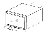
- FIG. 1 is an external view of a navigation device 1 according to an embodiment of the present invention.
- the navigation device there is, for example, an on-vehicle navigation device such as AVN (registered trademark. Audio Visual Navigation) of Fujitsu Ten Ltd.
- AVN registered trademark. Audio Visual Navigation
- the present invention is also applicable to, for example, an electronic device having a portable navigation function.
- the present invention is also applicable to an image processing apparatus that generates an image by being externally connected to or incorporated in a navigation apparatus or an electronic device having a portable navigation function.
- the navigation device 1 is a 2DIN (Deutsche Industrie Normen) main body / monitor integrated type car navigation device, and has a car navigation function for providing information on a route to a current location of a vehicle or a destination, It has a function of reproducing visual (hereinafter referred to as AV) content, a function of receiving a broadcast wave, and the like.
- the navigation device 1 is used in a state of being installed near the center of a dashboard easily accessible to the hands of passengers on the driver's seat and the front passenger's seat, and comprises a main unit 2 and a display unit 3.
- FIG. 2 is a block diagram of the navigation device 1.
- the main unit 2 is composed of electronic parts, and includes a brake detection unit 4, a reverse detection unit 5, a portable player interface 6, a broadcast wave reception unit 7, an external audio / video input unit 8, a GPS information reception unit 9, Vehicle speed detection unit 10, camera image input unit 11, amplifier 12, open / close control unit 13A, angle control unit 13B, angle sensor 14, motor 15, CD drive 16, card memory interface 17, reset button 18, gyro sensor 19, control unit There are 20 built-in.
- the display unit 3 mainly includes various devices for displaying a variety of information as an image to the occupants of the vehicle, and also plays a role of accepting a user operation, and the touch panel 21, the display processing unit 22, and the operation accepting unit An operation button 24 and an infrared ray receiving / emitting unit 25 are incorporated.
- the brake detection unit 4 detects whether the parking brake of the vehicle is applied and notifies the control unit 20 of this.
- the brake detection unit 4 detects the state of the brake based on the energization state of a switch that is turned on and off in conjunction with the movement of the parking brake lever (or pedal).
- the brake detection unit 4 electrically detects the conduction state of the switch via the terminal 26A.
- the reverse detection unit 5 detects whether the shift lever of the vehicle is reverse (reverse) and notifies the control unit 20 of this.
- the reverse detection unit 5 detects the state of the shift lever by turning on and off a switch that moves in conjunction with the shift lever.
- the reverse detection unit 5 electrically detects the conduction state of the switch via the terminal 26B.
- the portable player interface 6 is an interface for performing two-way communication with a portable player (for example, an iPod (registered trademark)) that reproduces music and the like.
- a portable player for example, an iPod (registered trademark)
- the portable player interface 6 starts bi-directional communication, sends an audio signal sent from the player to the control unit 20, and starts playback or music sent from the control unit 20.
- Send control signals such as sending to the player.
- the portable player interface 6 communicates with the player via a cord connected to the terminal 26C.
- the broadcast wave receiving unit 7 is a circuit configured of a one-segment tuner ("one segment" is under application for trademark registration), an AM tuner (AM: amplitude modulation), and an FM tuner (FM: frequency modulation).
- the broadcast wave receiving unit 7 controls the reception state of the tuner according to the control signal from the control unit 20, and sends to the control unit 20 the signal of the radio wave received by the antenna connected to the terminal 26D.
- the external audio / video input unit 8 is a circuit that receives a composite video signal and an audio signal from a video / audio device connected to the terminal 26E and sends the signal to the control unit 20.
- the GPS information receiving unit 9 receives a signal of a radio wave from a GPS satellite received by a GPS antenna connected to the terminal 26F, and sends the received signal to the control unit 20.
- the GPS is a system for positioning a vehicle based on radio waves from at least three satellites out of a large number of GPS satellites orbiting the earth.
- the GPS information receiving unit 9 processes signals of radio waves of these GPS satellites orbiting the earth.
- the signals from the GPS satellites received by the GPS information receiver 9 are used for car navigation.
- the vehicle speed detection unit 10 is a circuit that detects a vehicle speed pulse signal generated according to the rotation angle of the axle and sends this to the control unit 20.
- the vehicle speed pulse signal detected by the vehicle speed detection unit 10 is a step-like vehicle speed pulse signal output from a vehicle speed sensor or an electronic control unit that controls the engine or brake of the vehicle, and the vehicle speed is determined from the number of pulses per unit time. Used in If the number of pulses per unit time is increasing, the vehicle is accelerating, and if it is decreasing, the vehicle is decelerating.
- the correlation between the speed of the vehicle and the vehicle speed pulse changes in accordance with the manufacturer and model of the vehicle, the size of the mounted wheel, the air pressure, and the like.
- the correlation between the speed of the vehicle and the vehicle speed pulse is obtained from the correlation between the moving distance of the vehicle calculated based on the positioning result by GPS and the number of pulses detected while traveling between them. Updated appropriately.
- the vehicle speed detection unit 10 electrically detects a vehicle speed pulse signal output from the electronic control unit via the terminal 26G.
- the camera video input unit 11 is a circuit that receives a video signal from a back-eye camera, which is a video camera that captures the rear of the vehicle, and sends the video signal to the control unit 20. That is, when the reverse detection unit 5 detects a reverse of the vehicle, the camera image input unit 11 sends an image signal from the video camera connected to the terminal 26H to the control unit 20.
- the amplifier 12 is a circuit that amplifies an audio signal sent from the control unit 20 to a speaker installed in the vehicle compartment and connected to the terminal 26I.
- the amplifier 12 can arbitrarily change the amplification factor in accordance with the control signal from the control unit 20.
- the opening and closing control unit 13A is a circuit that performs the opening and closing operation of the display unit 3.
- the open / close control unit 13A opens / closes the display unit 3 by controlling the motor 15 or processing the signal from the angle sensor 14 in accordance with the control signal from the control unit 20.
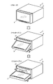
- FIG. 3 shows the open / close operation of the display unit 3 realized by the open / close control unit 13A that receives the control signal from the control unit 20 controlling the motor 15.
- the open / close control unit 13A can adjust the attitude of the display unit 3 in three steps as shown in FIG. 3, and closes the CD insertion slot 27 of the CD drive 16 (CD: Compact Disc).
- the angle control unit 13 B is a circuit that adjusts the angle of the display unit 3.
- the angle control unit 13B controls the motor 15 in accordance with the control signal from the control unit 20 or processes the signal from the angle sensor 14 in the same manner as the open / close control unit 13A, thereby making the angle of the display unit 3 adjust.
- the angle of the display unit 3 is a relative angle between the front of the main unit 2 and the front of the display unit 3 (that is, the surface of the touch panel 21) with an axis extending in the left-right direction of the navigation device 1 as the center. is there.
- FIG. 4 shows an angle adjustment state of the display unit 3 realized by the angle control unit 13B. As shown in FIG. 4, the angle control unit 13B can adjust the elevation angle of the display unit 3 in multiple steps to tilt up.
- the angle sensor 14 is a sensor that detects the angle of the display unit 3 and notifies the detected angle to the open / close control unit 13A and the angle control unit 13B by an electric signal.
- the motor 15 is a motor for adjusting the angle of the display unit 3 and moves the upper end of the display unit 3 up and down or moves the lower end of the display unit 3 back and forth.
- open / close control unit 13A and angle control unit 13B are the difference between the angle of display unit 3 detected by angle sensor 14 and the target value of the angle determined based on the control signal.
- the CD drive 16 is an optical disk reader for reading and reproducing a CD on which audio content such as music is recorded, and is constituted by an optical pickup lens, a light emitting element, a disk drive motor and the like.
- the card memory interface 17 is a memory card reader / writer that reads and writes non-volatile semiconductor memory cards that do not require storage and storage operations.
- the memory card inserted into the card memory interface 17 has a storage capacity of about 4 GB, and road information such as expressways and general roads, point information on various facilities such as theme parks and gas stations (hereinafter referred to as POI (Point The map data including “Of Interest” data, etc., and data such as telephone numbers and facility names are recorded.
- POI Point The map data including “Of Interest” data, etc.
- the control unit 20 realizes various functions such as car navigation route search by accessing map data recorded in the memory card.
- the gyro sensor 19 is a two-axis gyro sensor built in the main unit 2.
- the gyro sensor 19 is for enabling positioning of the vehicle even when the GPS information receiving unit 9 can not receive radio waves from GPS satellites.
- the position of the vehicle when the radio wave from the GPS satellite can not be received is calculated by the control unit 20 based on the vehicle speed detected by the vehicle speed detection unit 10 and the traveling direction of the vehicle detected by the gyro sensor 19.
- the control unit 20 is configured of a central processing unit (CPU), a read only memory (ROM), a random access memory (RAM), an input / output interface, and the like.
- CPU central processing unit
- ROM read only memory
- RAM random access memory
- the control unit 20 executes the computer program stored in the ROM, and uses data of the memory card inserted in the card memory interface 17, data stored in the RAM, etc. To realize the function. Details of various functions realized by the control unit 20 will be described later.
- the touch panel 21 is a GUI (Graphical User Interface) combining a color liquid crystal display and a touch sensor, and displays an image on a 7.0-inch EGA (Enhanced Graphics Adapter) liquid crystal display, and an icon displayed on the screen When an etc. is pressed, the touch sensor detects this.
- GUI Graphic User Interface
- the display processing unit 22 is a circuit that performs drawing processing on a screen displayed on the liquid crystal display of the touch panel 21.
- the display processing unit 22 draws the screen of the touch panel 21 by driving thin film transistors evenly arranged in a grid on the liquid crystal display based on the video signal sent from the control unit 20.
- the operation accepting unit 23 identifies a position on the screen that has been touched, and sends information on the identified position to the control unit 20.
- the operation button 24 is not a button (button image) displayed as an icon on the touch panel 21 but a mechanical button, and as shown in FIG. 1 etc., a push button type switch for operation disposed below the touch panel 21 It is.
- the operation buttons 24 are, in order from the left side of the display unit 3, an open / close button, a current location button, and a volume adjustment button.
- the volume adjustment button is set to increase the volume when the right side is pressed and to decrease the volume when the left side is pressed. When these buttons are pressed, the signal of the pressed button is sent to the control unit 20.
- the infrared light receiving / emitting unit 25 is an interface for bi-directional communication between the navigation device 1 and the mobile phone using infrared light, and is configured of a light emitting element that emits infrared light by electricity and a light receiving element that turns received infrared light into electricity. It is done.
- the infrared ray receiving / emitting unit 25 sends control signals and data sent from the control unit 20 to the mobile phone, and sends control signals and data sent from the mobile phone to the control unit 20.
- the infrared light receiving / emitting unit 25 is disposed below the touch panel 21 as shown in FIG.
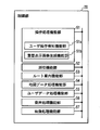
- FIG. 5 is a functional block diagram illustrating various functional units realized by the control unit 20.
- the control unit 20 controls the operation processing function unit 51, the positioning function unit 52, the route guidance function unit 53, the map data processing function unit 54, and the user data processing function unit 55 as shown in FIG. And a computer program for realizing the audio processing function unit 56 and the video processing function unit 57.
- the operation processing function unit 51 displays an operation screen for controlling the operation of the various function units on the touch panel 21 through the video processing function unit 57, or from the operation reception unit 23, the operation button 24, and the reset button 18.
- the operation signal is processed to control the operation of various functional units.
- the user can use the buttons included in the basic screen serving as the background of the pop-up image, such as a multi-screen including a navigation area and an AV area, a navigation full screen, and an AV full screen.
- a user operation detection function unit 51a for detecting a touch operation, and a superimposed display image generation function unit 51b for generating a pop-up image superimposed and displayed on the basic screen when a touch operation by a user is detected are included.
- the positioning function unit 52 is sent from the information of the radio wave from the satellite sent from the GPS information receiving unit 9, the information of the vehicle speed notified from the vehicle speed detection unit 10, and the gyro sensor 19.
- the position (latitude and longitude) of the vehicle is determined based on the angular velocity information.
- the route guidance function unit 53 is a functional unit that searches for a route from the current location of the vehicle to a destination set by the user and performs route guidance.
- the route guidance function unit 53 finds out a traveling route from the position of the vehicle measured by the positioning function unit 52 to the destination from map data of a memory card inserted in the card memory interface 17. Then, the route of the vehicle is guided by voice and video based on the relationship between the traveled route and the position of the vehicle.
- the map data processing function unit 54 acquires map data of a memory card inserted into the card memory interface 17, data of a traveling route searched by the route guidance function unit 53, and data acquired from FM broadcast waves via the broadcast wave receiving unit 7.
- the graphic data of the map to be displayed on the touch panel 21 is generated based on the data of the road traffic information of VICS (registered trademark), the position data of the vehicle measured by the positioning function unit 52, and the like.
- the user data processing function unit 55 writes location information such as location information (for example, location information of a home) to be registered by the user, history information of route search, setting information such as display / non-display of icons in the RAM, or reads out from the RAM To
- the audio processing function unit 56 is a functional unit that processes an audio signal output from the speaker via the amplifier 12. That is, the audio processing function unit 56 sends the radio broadcast received by the broadcast wave receiving unit 7, the audio signal acquired by the portable player interface 6 from the player, the audio signal reproduced by the CD drive 16 to the amplifier 12, An audio signal of the route guidance from the route guidance function unit 53 is superimposed on the audio signal and sent to the amplifier 12 or the like.
- the video processing function unit 57 is a functional unit that generates video data to be displayed on the touch panel 21. That is, the video processing function unit 57 combines the data of the operation screen generated by the operation processing function unit 51 and the data of the display map screen generated by the map data processing function unit 54 and sends it to the display processing unit 22. Or sends video data of a television broadcast received by the broadcast wave receiving unit 7 to the display processing unit 22 or displays a video signal from the camera video input unit 11 in conjunction with the detection of vehicle retraction by the reverse detection unit 5 It is sent to the processing unit 22. When the brake detection unit 4 detects the release of the parking brake while transmitting the video data of the television broadcast to the display processing unit 22, the video processing function unit 57 stops the notification of the video data.
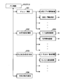
- FIG. 6 is a screen transition diagram of the main screen of the navigation device 1
- FIG. 7 is a screen transition diagram concerning navigation.
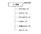
- FIG. 8 is a diagram showing a display mode of the AV screen.
- the operation of the navigation device 1 will be described based on FIGS.
- the opening screen (D101) will be described.
- the control unit 20 executes a computer program stored in the ROM to initialize the navigation device 1, and various functions shown in FIG. Realize the department.
- the video processing function unit 57 refers to the data of the opening screen stored in the ROM, and causes the touch panel 21 to display the opening screen.
- each functional unit of the control unit 20 executes the following process. That is, the operation processing function unit 51 scans the signals from the operation reception unit 23, the operation button 24, and the reset button 18 to receive the user operation.
- the positioning function unit 52 processes the positioning information acquired by the GPS information receiving unit 9 and the signals of the vehicle speed detection unit 10 and the gyro sensor 19 to measure the position of the vehicle.
- the map data processing function unit 54 accesses the card memory inserted in the card memory interface 17, and reads out map data around the vehicle position determined by the positioning function unit 52.
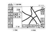
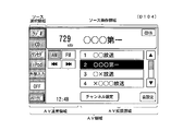
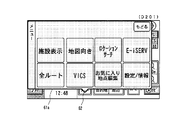
- FIG. 9 is a diagram of a multi-screen.
- the image processing function unit 57 displays the screen of the AV area on which the operation buttons of AV type are arranged on the left side of the touch panel 21, and the screen of the navigation area on which the map of navigation and the operation buttons are arranged. Is displayed on the right side of the touch panel 21.
- the AV area is further divided into a source selection area in which operation buttons for selecting a source are collectively displayed and a source operation area in which buttons and information related to the selected source are displayed.
- the video processing function unit 57 sets “radio”, “CD”, “one seg”, “iPod”, “external input”, “OFF”, and so on in the source selection area in the AV area. Display the "AV" button. When any source button is touched, that source is selected. In the example of FIG. 9, “radio” is selected, and operation buttons and information related to the selected source such as the reception frequency, the AM / FM switching button, and the channel selection button are displayed in the source operation area. The state is illustrated. Therefore, at this time, the audio processing function unit 56 outputs the audio signal of AM broadcast received by the broadcast wave receiving unit 7 from the speaker via the amplifier 12.
- the video processing function unit 57 has a menu, a destination, a periphery, and a home, in addition to the map drawn in the navigation area based on the map data read by the map data processing function unit 54. , "Navi”, "map enlargement”, and “map reduction” buttons are displayed. Note that, in the multi-screen (D102), there are two, an AV area and a navigation area, so the AV area is narrower than that of the AV full screen (D104). Therefore, in the source operation area of the multi-screen (D102), only basic ones among operation buttons and information related to the source are displayed.
- the operation processing function unit 51 detects that the “AV” button is pressed in this state, the video processing function unit 57 transitions to the screen display state of the AV full screen (D104).
- the other button is pressed will be described in detail after the description of the navigation full screen (D103) and the AV full screen (D104).
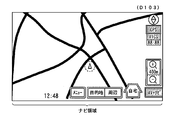
- FIG. 10 is a diagram of the navigation full screen. As shown in FIG. 10, the video processing function unit 57 erases the AV area and displays the navigation area on the touch panel 21 on the full screen.
- the video processing function unit 57 displays the screen such that the icon of the vehicle position displayed on the navigation full screen is positioned at the center of the navigation area. Therefore, when the display screen of the touch panel 21 transitions from the multi-screen (D102) to the navigation full-screen (D103), the display of the icon of the vehicle position and the map slightly scrolls in the screen. On the other hand, the video processing function unit 57 displays a screen so that operation buttons such as “menu” and “destination” are at the same position on the display screen of the touch panel 21.
- the display screen of the touch panel 21 transitions from the multi-screen (D102) to the navigation full screen (D103), the navigation operation buttons and the like are not scrolled on the screen of the touch panel 21 and continue to be displayed at the same position.
- the display is switched to the “AV + Navi” button only for the “Navi” button.
- the video processing function unit 57 switches the display from the navigation full screen (D103) to the multi-screen (D102).
- FIG. 11 is a diagram of the AV full screen. As shown in FIG. 11, the video processing function unit 57 erases the navigation area and displays the AV area on the touch panel 21 on the full screen.
- the "radio”, “CD”, “one seg”, “iPod”, “external input”, and “OFF” buttons are source selection areas. Is displayed on. Also, in the AV area, the source operation area is expanded, and the names of the broadcasting stations and preset channel selection buttons, channel setting buttons, and sound setting buttons which are not displayed in the multi-screen (D102) are displayed. In addition, “CDIN” is displayed to indicate that a CD is inserted in the CD drive 16. Here, in the AV area, operation buttons such as "radio" displayed on the multi-screen (D102) are displayed at the same position.
- the display is switched to the “AV + Navi” button only for the “Navi” button.
- an area displayed on both the multi-screen and the AV full screen is referred to as an “AV normal area”, and an area displayed only on the AV full screen is referred to as an “AV extended area”.
- the video processing function unit 57 switches the display from the AV full screen (D104) to the multi screen (D102).
- the AV full screen (D104) since the navigation area does not exist, the AV area is wider than that in the multi-screen (D102). Therefore, in the source operation area of the AV full screen (D104), all operation buttons and information related to the source are displayed.
- the display area of the source operation button and information displayed only in the case of the AV full screen (D104) is the "AV extension area", and constitutes a part of the source operation area.
- the display area of the source operation button and information displayed on both the multiscreen (D102) and the AV full screen (D104) is the "AV normal area", and part of the source operation area and the source selection area And make up.
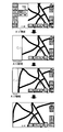
- FIG. 6 is a diagram showing how the navigation area and the AV area move on the screen when the screen transitions from the multiscreen (D102) to the navigation full screen (D103) or the AV full screen (D104) will be described in detail.
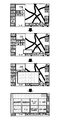
- FIG. 12 is a diagram showing how the AV area disappears when transitioning from the multi-screen (D102) to the navigation full-screen (D103).
- FIG. 13 is a diagram showing how the navigation area disappears when transitioning from the multi-screen (D103) to the AV full-screen (D104).
- the image processing function unit 57 displays the screen so that the navigation area and the AV area are scrolled and viewed. That is, when the display processing is switched from the multi-screen to the navigation full screen, the video processing function unit 57 causes the AV area to gradually leave to the left, in other words, the display area of the AV area gradually decreases. The screen is displayed so as to scroll so that the display area of the navigation area gradually increases. In addition, when the display processing is switched from the multi-screen to the AV full screen, the video processing function unit 57 displays a screen so that the AV area gradually enters the right side. Thus, the user can feel as if the AV screen is inserted and removed on the navigation screen.
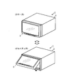
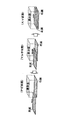
- FIG. 14 is a conceptual diagram showing the screen transition of the main screen.
- the user as shown in FIG. 14, corresponds to the left side surface (corresponding to the AV screen referred to in the present embodiment) on the right side surface (corresponding to the navigation screen referred to in the present embodiment) viewed when looking into the display window.
- the main screen of the navigation device 1 can be operated with an image such that is inserted and removed from the left side. Therefore, it is easy to understand where you are now, and you can operate without getting lost.
- FIG. 7 the flow of screen transition shown in FIG. 7, that is, various buttons displayed in the navigation area of the multi-screen (D102) or the navigation full screen (D103) (hereinafter referred to as "basic screen") is operated.
- a menu screen (D201) including a pop-up image, a destination setting screen (D202), or a peripheral facility search screen (D203) is displayed, and the screen display process when a function is provided using each screen
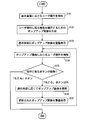
- FIG. 15 is a screen display process in the case where a pop-up image is displayed by operating various buttons displayed on the basic screen in the present embodiment, and various functions are provided using the displayed pop-up image.
- It is a flowchart which shows a flow.
- a basic screen such as a multiscreen (D102) or a navigation full screen (D103) generated by the video processing function unit 57 is output to the touch panel 21 and displayed. It is started.
- steps S101 to S103 an operation on a display element such as a button displayed in the basic screen is detected, and a pop-up image (superimposed display image) is displayed.
- the user operation detection function unit 51a detects that the various buttons displayed in the navigation area of the basic screen displayed on the touch panel 21 are touched (step S101)
- the superimposed display image generation function unit 51b performs the operation A function corresponding to the detected button is identified, and a pop-up image for providing this function is generated (step S102).
- the software module to be executed to provide the function and the data of the generated pop-up image are recorded in advance in the ROM in association with identification information of buttons (display elements) displayed on the basic screen. And identified using identification information of the display element operated by the user.
- the video processing function unit 57 generates a video signal for superimposing the generated pop-up image on the basic screen, and outputs the video signal to the touch panel 21 (step S103), thereby popping up in front of the basic screen.
- a screen such as a menu screen (D201), a destination setting screen (D202), and a surrounding facility search screen (D203) on which an image is superimposed and displayed is displayed on the touch panel 21.
- the pop-up image is an image that stands up in front of the basic screen to provide a function associated with the button when the button displayed on the screen is pressed, and, for example, items of the menu It is an image to be displayed.
- the menu screen (D201) is a screen including a pop-up image 61a for providing a menu selection function for setting the navigation apparatus 1 and the like, and is displayed in the navigation area of the multiscreen (D102) or the navigation full screen (D103). It is displayed when the user operation detection function unit 51a detects that the displayed "menu" button has been pressed.
- FIG. 16 is a diagram of the menu screen (D201).
- the image processing function unit 57 as shown in FIG. 16, is a balloon for showing the relativity between the "menu" button in the navigation area and the pop-up image 61a for the menu selection function newly displayed according to the user operation.
- a pop-up image 61a is displayed that includes the word-like relevance display image 62.
- the video processing function unit 57 performs an animation display for giving a visual effect to be displayed while the pop-up image 61a is gradually enlarged starting from the "menu" button, and the multi-screen (D102) further pops up.
- FIG. 17 is a diagram showing an animation at the time of transition from the multi-screen (D102) to the menu screen (D201). Therefore, the user can easily grasp visually that the menu screen is displayed transitioning from the multi-screen, and can operate without hesitation.
- the menu screen (D201) displays an icon, a button for user setting such as a facility display, and a button for editing a favorite spot.
- the user data processing function unit 55 stores point information and the like registered by the user in the RAM in the control unit 20.
- the destination setting screen (D202) is a screen including a pop-up image 61b for providing a destination setting function, and is displayed in the navigation area of the multiscreen (D102) or the navigation full screen (D103). It is displayed when the user operation detection function unit 51a detects that the "destination" button has been pressed.
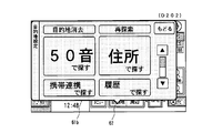
- FIG. 18 is a diagram of a destination setting screen (D202).
- the video processing function unit 57 displays the destination setting screen (D 202) on the touch panel 21.
- the video processing function unit 57 displays the relevancy, accompanied by an animation display for giving a visual effect to be displayed while gradually enlarging with the "destination" button in the navigation area as the starting point.
- a pop-up image 61 b including the image 62 is displayed.
- the destination setting screen (D 202) there is a “Find by sound” button, a “Find by address” button, a “Find by cell phone link” button, a “Find by history” button, a “Find by favorite” button, Destination search buttons such as “Find by phone number” button, “Find by facility / genre” button, “Find by map” button, “Find by map code” button, and “Find by additional data” button included. These destination search buttons are displayed in the pop-up image 61b of the destination setting screen (D202) so that all buttons can be browsed by the scroll operation.
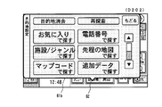
- FIG. 19 is a diagram showing a state in which the destination search button display area in the pop-up image 61 b shown in FIG. 18 is scrolled downward in the present embodiment.
- a scroll bar and a scroll button are displayed on the destination setting screen (D202), and scroll display by a user's touch operation is possible.
- the video processing function unit 57 scrolls the destination search button display area in the pop-up image 61b downward.
- each button can be displayed in a large size and in an easy-to-see manner in the display area of a limited size of the touch panel 21 (7.0 inches in this embodiment). You can do it.
- the frequently used button is displayed larger and higher than the other buttons.
- the “Find by Fifty Sounds” button and the “Find by Address” button are displayed larger and higher than the other destination search buttons.
- the peripheral facility search screen (D203) is a screen including a pop-up image 61c for providing a peripheral facility search function, and "peripheral" displayed in the navigation area of the multiscreen (D102) or the navigation full screen (D103)
- the display is triggered by the user operation detection function unit 51a detecting that the button is pressed.
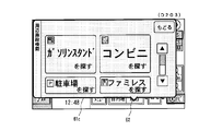
- FIG. 20 is a diagram of the peripheral facility search screen (D203).
- the operation processing function unit 51 detects that the “periphery” button is pressed
- the video processing function unit 57 displays the peripheral facility search screen (D203) on the touch panel 21.
- the image processing function unit 57 causes the pop-up image 61 c including the relevance display image 62 to be accompanied by an animation display for giving a visual effect to be displayed while gradually enlarging starting from the “periphery” button of the navigation area. indicate. Then, as in the case of the destination search screen (D202) described above, when any button is pressed, a screen corresponding to this is displayed. That is, when the "periphery" button is pressed, the video processing function unit 57 displays a button that allows the user to select the category of the facility to be searched, and when the category to be searched is specified, the periphery of the vehicle position is selected. The facilities corresponding to the specified category, such as the gas station and convenience store located in, are searched out and displayed in order of proximity to the vehicle.
- the specified category such as the gas station and convenience store located in
- the destination is set on the above-described destination setting screen (D202) or the peripheral facility search screen (D203), or the multiscreen (D102) or the navigation full screen (D103)
- the displayed "home" button is pressed to set the destination, and it is displayed when the route guidance by the route guidance function unit 53 is started.
- the route guidance function unit 53 guides the route based on the vehicle position measured by the positioning function unit 52 and the map data read from the card memory by the map data processing function unit 54.
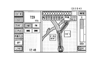
- the route guidance function unit 53 displays an intersection enlarged screen (D204) and passes voice data for route guidance to the voice processing function unit 56.
- FIG. 21 is a diagram showing an intersection enlargement screen (D204). As shown in FIG. 21, an enlarged view of an intersection is displayed in the navigation area, and the route of the vehicle is indicated by an arrow. At this time, audio / visual operation buttons and the like are displayed in the AV area.
- steps S104 to S107 an operation on the display element displayed in the pop-up image is detected, and the display content of the pop-up image is updated.
- the user operation detection function unit 51a detects a touch operation on a display element in the pop-up image such as a destination search button displayed on the destination setting screen (D202) (step S104)
- the type of the user operation is determined (Step S105).
- the detected user operation is an operation such that the pop-up image is closed, such as a touch operation on the “Back” button displayed in each pop-up image, the pop-up image is closed and the basic screen (here, A multiscreen (D102) or a navigation full screen (D103) is displayed on the front.
- the superimposed display image generation function unit 51b ends the generation of the pop-up image, and the video processing function unit 57 performs the basic screen of the pop-up image. End the superimposed display on. Thereafter, the process shown in the present flowchart ends.
- the superimposed display image generation function unit 51b updates the display content in the pop-up image by generating the pop-up image updated according to the operation.
- the data of the pop-up image to be updated is associated with the identification information of the buttons (display elements) displayed in the pop-up image and recorded in advance in the ROM, and the identification of the display element operated by the user Identified using information.
- the video processing function unit 57 generates a video signal for superimposing and displaying the generated pop-up image on the basic screen, and outputs the video signal to the touch panel 21 (step S107). Update the display of the displayed popup image.
- the video processing function unit 57 displays a screen corresponding to this.
- the image processing function unit 57 displays, for example, a screen for character input when the “search with 50 sounds” button is pressed, and displays a screen for selecting prefectures etc. when the “search by address” button is pressed.
- the communication data provided from the mobile phone by the infrared receiving / emitting unit 25 includes location information such as the latitude and longitude of the destination, or the address and the telephone number.
- the route guidance function unit 53 detects the vehicle itself measured by the positioning function unit 52. Find the shortest route to the location and destination and start route guidance.
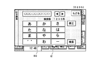
- FIG. 22 shows the display image of the 50-sound search screen (D205) displayed in response to the operation of the “search with 50 sounds” button displayed on the destination setting screen (D202) in the present embodiment.
- FIG. In the Japanese syllabary search screen (D205), a button for inputting a character string for search is arranged.
- a character string input interface having a format capable of selecting characters included in the consonant string assigned to the button by operating the button in which the first character of each consonant string is respectively described one to a plurality of times. It is adopted. For example, to input the character "ku", the user can select “ku” by touching the "ka” button three times.
- a cloud point / semi-cloud point button and a long sound button are also displayed.
- the input character string is displayed in the input character string display area at the top of the pop-up image 61d, and the user inputs a desired character string using this interface, and touches the “search” button to perform the purpose. You can search the ground.
- the pop-up image 61d included in the Japanese syllabary search screen (D205) is, like the destination setting screen (D202), a balloon-like relativity display image showing the relativity between the "destination" button and the pop-up image 61d. Including 62.
- the relevance display image 62 is subsequently searched for and the relevance to the "destination" button continues even when the search results are displayed in the updated pop-up image (not shown).
- the relevancy with the button that is the trigger of the pop-up image is continuously displayed, thereby the user can display the currently displayed screen. However, by first performing what kind of operation it is possible to easily grasp the displayed screen.
- the user proceeds from the destination setting screen (D202) to the Japanese syllabary search screen (D205) and further advances to the search result screen (not shown).
- the display of the relevance display image 62 it is possible to intuitively understand that the operation currently being performed is the operation started by operating the "destination" button. Also, this gives the user a sense of security for the interface of the navigation device 1.
- the display mode of the AV screen of the navigation device 1 will be described.
- a radio mode As shown in FIG. 8, on the AV screen of the navigation device 1, six screens of a radio mode, a CD mode, a one segment mode, an iPod mode, an external input mode, and an off mode are prepared.
- the video processing function unit 57 displays the AV operation screen of the mode corresponding to this.
- the image processing function unit 57 displays the frequency of the radio and the tuning button as shown in FIG. The same is true for CD and iPod buttons.
- the video processing function unit 57 displays a channel selection button or the like in the AV area and displays the navigation area as the image from the broadcast wave receiving unit 7 Or switch to the video of the external audio / video input unit 8.
- the brake detection unit 4 detects the release of the parking brake signal
- the video processing function unit 57 stops the video display from the broadcast wave reception unit 7 or the external audio / video input unit 8.
- the pop-up images 61a to 61d displayed upon reception of a touch operation on a display element such as a button displayed on the basic screen are operated on
- a display element such as a button displayed on the basic screen
- the user can It is possible to easily grasp the relationship between the operation and its origin and the continuity from the origin to the operation.
- a function called by the basic screen using a pop-up image and continuously displaying the basic screen in the background it is possible for the user to perform the operation currently being performed and the starting point thereof. Relevance can be easily grasped.
- the pop-up image displayed in response to the operation on the button or the like arranged in the navigation area has been described, but the button arranged in the AV area of the multiscreen (D102) or the AV full screen (D104)
- the present invention may also be applied to pop-up images displayed in response to operations such as, etc.
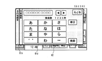
- FIG. 23 is already displayed on the destination setting screen (D202) when the “find with 50 sounds” button is touch-operated on the destination setting screen (D202) of FIG. 18 in another embodiment. It is a figure which shows the 50 sound search screen (D206) displayed not by updating the display content of the pop-up image 61b but by further superimposing the pop-up image 61d for 50 sound search on the front of the pop-up image 61b.
- the superimposed display image generation unit 51 b when the user operation detection function unit 51 a detects a touch operation on the “search with 50 sounds” button, the superimposed display image generation unit 51 b generates a pop-up image 61 d for 50 sound search as a new pop-up image
- the processing function unit 57 superimposes and displays the generated pop-up image 61 d in front of the pop-up image 61 b.
- the user can easily grasp the relation between the operation currently being performed and the starting point thereof and the continuity from the starting point to the operation, and it is further displayed. It becomes possible to grasp also the operation progress to the screen. Moreover, according to such a display method, it is possible to return from the Japanese syllabary search screen (D206) to the destination setting screen (D202) without using the “return” button. That is, when the user operation detection function unit 51a detects a touch operation on a tab portion of the pop-up image 61b (in FIG.
- the present invention is applied to a car navigation system, but the present invention is not limited to this.
- the present invention may be applied to a portable electronic device having a navigation function, such as a portable navigation device or a mobile phone.
- the present invention is applied to a navigation apparatus as an information processing apparatus capable of processing navigation information, but the present invention is not limited to this.
- the present invention may be applied to an image processing apparatus that generates a navigation image by being externally connected to or incorporated in a navigation device having a touch panel or a portable electronic device.
Landscapes
- Engineering & Computer Science (AREA)
- Theoretical Computer Science (AREA)
- Radar, Positioning & Navigation (AREA)
- Remote Sensing (AREA)
- Physics & Mathematics (AREA)
- General Physics & Mathematics (AREA)
- Human Computer Interaction (AREA)
- General Engineering & Computer Science (AREA)
- Automation & Control Theory (AREA)
- Mathematical Physics (AREA)
- Business, Economics & Management (AREA)
- Educational Administration (AREA)
- Educational Technology (AREA)
- Navigation (AREA)
- Instructional Devices (AREA)
- Digital Computer Display Output (AREA)
- User Interface Of Digital Computer (AREA)
- Traffic Control Systems (AREA)
Priority Applications (2)
| Application Number | Priority Date | Filing Date | Title |
|---|---|---|---|
| US13/063,636 US20110164053A1 (en) | 2008-09-12 | 2009-09-11 | Information processing device and information processing method |
| EP09813155.0A EP2339444A4 (en) | 2008-09-12 | 2009-09-11 | INFORMATION PROCESSING DEVICE AND INFORMATION PROCESSING METHOD |
Applications Claiming Priority (2)
| Application Number | Priority Date | Filing Date | Title |
|---|---|---|---|
| JP2008-234446 | 2008-09-12 | ||
| JP2008234446A JP5219705B2 (ja) | 2008-09-12 | 2008-09-12 | 情報処理装置および情報処理方法 |
Publications (1)
| Publication Number | Publication Date |
|---|---|
| WO2010030009A1 true WO2010030009A1 (ja) | 2010-03-18 |
Family
ID=42005259
Family Applications (1)
| Application Number | Title | Priority Date | Filing Date |
|---|---|---|---|
| PCT/JP2009/065959 Ceased WO2010030009A1 (ja) | 2008-09-12 | 2009-09-11 | 情報処理装置および情報処理方法 |
Country Status (5)
| Country | Link |
|---|---|
| US (1) | US20110164053A1 (enExample) |
| EP (1) | EP2339444A4 (enExample) |
| JP (1) | JP5219705B2 (enExample) |
| CN (1) | CN101673175B (enExample) |
| WO (1) | WO2010030009A1 (enExample) |
Families Citing this family (18)
| Publication number | Priority date | Publication date | Assignee | Title |
|---|---|---|---|---|
| JP2012068785A (ja) * | 2010-09-22 | 2012-04-05 | Konica Minolta Business Technologies Inc | 画像処理装置、その制御プログラムおよびその制御方法 |
| US20130088511A1 (en) * | 2011-10-10 | 2013-04-11 | Sanjit K. Mitra | E-book reader with overlays |
| CN102520867B (zh) * | 2011-12-21 | 2014-07-30 | 深圳市航盛电子股份有限公司 | 一种汽车导航系统及其导航方法 |
| KR101952702B1 (ko) | 2012-06-01 | 2019-02-28 | 삼성전자주식회사 | 개인 정보에 기초한 서비스를 제공하는 사용자 단말 장치 및 그 서비스 제공 방법 |
| JP6381032B2 (ja) * | 2012-06-08 | 2018-08-29 | 日本電気株式会社 | 電子機器、その制御方法及びプログラム |
| US20140152600A1 (en) * | 2012-12-05 | 2014-06-05 | Asustek Computer Inc. | Touch display device for vehicle and display method applied for the same |
| USD723053S1 (en) * | 2012-12-28 | 2015-02-24 | Nissan Motor Co., Ltd. | Display screen with a graphical user interface |
| WO2014203888A1 (ja) * | 2013-06-21 | 2014-12-24 | 矢崎総業株式会社 | 表示装置 |
| JP6132263B2 (ja) * | 2014-04-11 | 2017-05-24 | 株式会社デンソー | 表示制御装置 |
| USD787539S1 (en) * | 2015-10-06 | 2017-05-23 | N3N Co., Ltd. | Display screen or portion thereof with a graphical user interface |
| CN105892663B (zh) * | 2016-03-31 | 2021-02-19 | 联想(北京)有限公司 | 一种信息处理方法及电子设备 |
| US10259581B2 (en) * | 2016-04-04 | 2019-04-16 | Panasonic Intellectual Property Management Co., Ltd. | Monitor device having a connecting surface tilted downward |
| CN107331186B (zh) * | 2016-04-28 | 2020-07-10 | 上海炬宏信息技术有限公司 | 自车位置在交通路况简图上的定位方法 |
| US11586338B2 (en) * | 2017-04-05 | 2023-02-21 | Open Text Sa Ulc | Systems and methods for animated computer generated display |
| JP6960792B2 (ja) | 2017-07-26 | 2021-11-05 | 株式会社デンソーテン | 情報出力装置および情報出力方法 |
| CN111935357B (zh) * | 2020-08-17 | 2021-07-27 | 北京字节跳动网络技术有限公司 | 多媒体播放方法及设备 |
| JP7788073B2 (ja) * | 2022-03-16 | 2025-12-18 | スズキ株式会社 | 自動車用ディスプレイ |
| JP2025135522A (ja) * | 2024-03-05 | 2025-09-18 | 株式会社Subaru | 車両用表示装置 |
Citations (6)
| Publication number | Priority date | Publication date | Assignee | Title |
|---|---|---|---|---|
| JPH10320166A (ja) * | 1997-05-22 | 1998-12-04 | Shimadzu Corp | ポップアップ表示装置および材料試験機用ポップアップ表示装置 |
| JP2004061523A (ja) * | 2002-06-07 | 2004-02-26 | Clarion Co Ltd | 表示制御装置 |
| JP2004075206A (ja) | 2002-08-09 | 2004-03-11 | Hitachi Constr Mach Co Ltd | 建設機械の情報表示装置 |
| JP2004289691A (ja) * | 2003-03-24 | 2004-10-14 | Konica Minolta Holdings Inc | 画像形成装置および操作部表示方法 |
| JP2008033763A (ja) | 2006-07-31 | 2008-02-14 | Xanavi Informatics Corp | 車載電子機器およびナビゲーション装置 |
| JP2008234446A (ja) | 2007-03-22 | 2008-10-02 | Nec Corp | データ整合性チェック方法およびデータ整合性チェックシステム |
Family Cites Families (54)
| Publication number | Priority date | Publication date | Assignee | Title |
|---|---|---|---|---|
| US5140678A (en) * | 1990-05-04 | 1992-08-18 | International Business Machines Corporation | Computer user interface with window title bar icons |
| US5726688A (en) * | 1995-09-29 | 1998-03-10 | Ncr Corporation | Predictive, adaptive computer interface |
| US6084951A (en) * | 1997-04-23 | 2000-07-04 | Nortel Networks Corporation | Iconized name list |
| US6278991B1 (en) * | 1997-08-22 | 2001-08-21 | Sap Aktiengesellschaft | Browser for hierarchical structures |
| US7256770B2 (en) * | 1998-09-14 | 2007-08-14 | Microsoft Corporation | Method for displaying information responsive to sensing a physical presence proximate to a computer input device |
| KR20000061224A (ko) * | 1999-03-24 | 2000-10-16 | 구자홍 | 영상기기의 메뉴화면 표시방법 |
| GB9920327D0 (en) * | 1999-08-28 | 1999-11-03 | Koninkl Philips Electronics Nv | Menu display for a graphical user interface |
| US6552738B1 (en) * | 1999-11-18 | 2003-04-22 | Trident Microsystems, Inc. | User interface for control of a display device |
| KR100434265B1 (ko) * | 1999-12-07 | 2004-06-04 | 엘지전자 주식회사 | 온 스크린 디스플레이 장치 및 온 스크린 디스플레이장치에서의 메뉴 디스플레이 방법 |
| US6396520B1 (en) * | 2000-01-05 | 2002-05-28 | Apple Computer, Inc. | Method of transition between window states |
| KR100460105B1 (ko) * | 2000-02-22 | 2004-12-03 | 엘지전자 주식회사 | 이동통신 단말기의 메뉴 검색 방법. |
| JP4557374B2 (ja) * | 2000-06-15 | 2010-10-06 | キヤノン株式会社 | 画像表示装置及びその制御方法、並びに記憶媒体 |
| EP1195673B1 (de) * | 2000-10-04 | 2007-05-09 | Siemens Aktiengesellschaft | Kraftfahrzeug-Multimediasystem mit animierter Anzeigefunktion |
| US7216303B2 (en) * | 2002-01-03 | 2007-05-08 | International Business Machines Corporation | Menu emulation for content browser clients |
| JP3933955B2 (ja) * | 2002-02-19 | 2007-06-20 | 株式会社日立製作所 | 車載装置 |
| US6857105B1 (en) * | 2002-02-19 | 2005-02-15 | Adobe Systems Incorporated | Method and apparatus for expanding and contracting graphical function displays |
| EP1369770A1 (en) * | 2002-06-06 | 2003-12-10 | Sony Ericsson Mobile Communications AB | Graphical user interface for expandable menus |
| JP3946592B2 (ja) * | 2002-07-18 | 2007-07-18 | シャープ株式会社 | ユーザインタフェース用表示装置および画像形成装置 |
| US7058902B2 (en) * | 2002-07-30 | 2006-06-06 | Microsoft Corporation | Enhanced on-object context menus |
| US6956503B2 (en) * | 2002-09-13 | 2005-10-18 | Canon Kabushiki Kaisha | Image display apparatus, image display method, measurement apparatus, measurement method, information processing method, information processing apparatus, and identification method |
| KR100474453B1 (ko) * | 2002-10-01 | 2005-03-10 | 삼성전자주식회사 | 채널설정이 용이한 영상디스플레이장치 |
| FR2849318B1 (fr) * | 2002-12-24 | 2005-02-18 | Radiotelephone Sfr | Procede de navigation optimisee dans les menus d'affichage d'un terminal mobile et terminal mobile associe |
| US7444598B2 (en) * | 2003-06-30 | 2008-10-28 | Microsoft Corporation | Exploded views for providing rich regularized geometric transformations and interaction models on content for viewing, previewing, and interacting with documents, projects, and tasks |
| US7503013B2 (en) * | 2003-07-17 | 2009-03-10 | Cablevision Systems Corporation | System and method for vertical path navigation |
| US7594188B2 (en) * | 2003-08-21 | 2009-09-22 | Carl Zeiss Ag | Operating menu for a surgical microscope |
| US7418670B2 (en) * | 2003-10-03 | 2008-08-26 | Microsoft Corporation | Hierarchical in-place menus |
| JP4189297B2 (ja) * | 2003-10-29 | 2008-12-03 | 株式会社ナビタイムジャパン | 経路案内システム、携帯端末、サーバ、プログラム、記録媒体 |
| DE10360656A1 (de) * | 2003-12-23 | 2005-07-21 | Daimlerchrysler Ag | Bediensystem für ein Fahrzeug |
| KR20050090823A (ko) * | 2004-03-10 | 2005-09-14 | 삼성전자주식회사 | Osd 메뉴를 표시하는 영상촬영기기 및 그 표시방법 |
| US20060020904A1 (en) * | 2004-07-09 | 2006-01-26 | Antti Aaltonen | Stripe user interface |
| US20060041846A1 (en) * | 2004-08-19 | 2006-02-23 | International Business Machines Corporation | Method of window management for a windowing system |
| US7643917B2 (en) * | 2004-08-26 | 2010-01-05 | Harman Becker Automotive Systems Gmbh | Vehicle multimedia system |
| JP4134008B2 (ja) * | 2004-11-19 | 2008-08-13 | 任天堂株式会社 | 画像処理装置および画像処理プログラム |
| EP1677182B1 (en) * | 2004-12-28 | 2014-04-23 | Sony Mobile Communications Japan, Inc. | Display method, portable terminal device, and display program |
| US20060146055A1 (en) * | 2005-01-06 | 2006-07-06 | Raymond Chow | Graphics controller providing for animated windows |
| KR100716288B1 (ko) * | 2005-06-17 | 2007-05-09 | 삼성전자주식회사 | 디스플레이장치 및 그 제어방법 |
| JP2007052403A (ja) * | 2005-07-19 | 2007-03-01 | Canon Inc | 表示装置及び表示方法及びプログラム及び記憶媒体 |
| JP4815927B2 (ja) * | 2005-07-27 | 2011-11-16 | ソニー株式会社 | 表示装置、メニュー表示方法、メニュー表示方法のプログラム及びメニュー表示方法のプログラムを記録した記録媒体 |
| JP4701060B2 (ja) * | 2005-10-05 | 2011-06-15 | クラリオン株式会社 | ナビゲーション装置 |
| KR100617691B1 (ko) * | 2005-10-31 | 2006-08-28 | 삼성전자주식회사 | 휴대단말기의 메뉴 디스플레이 방법 |
| JP2007153197A (ja) * | 2005-12-07 | 2007-06-21 | Mazda Motor Corp | 車両用情報表示装置 |
| US8280742B2 (en) * | 2005-12-16 | 2012-10-02 | Panasonic Corporation | Input device and input method for mobile body |
| US7475359B2 (en) * | 2006-02-09 | 2009-01-06 | International Business Machines Corporation | User interface for a tabbed pane |
| KR101269172B1 (ko) * | 2006-06-21 | 2013-05-30 | 삼성전자주식회사 | 메뉴화면 제공방법 및 이를 적용한 영상기기 |
| US7739031B2 (en) * | 2006-09-05 | 2010-06-15 | Nissan Technical Center North America, Inc. | Vehicle on-board unit |
| US8316320B2 (en) * | 2006-10-03 | 2012-11-20 | Verizon Patent And Licensing Inc. | Expandable history tab in interactive graphical user interface systems and methods |
| JP4811287B2 (ja) * | 2007-01-31 | 2011-11-09 | ブラザー工業株式会社 | 階層構造表示装置および階層構造表示プログラム |
| US20080229218A1 (en) * | 2007-03-14 | 2008-09-18 | Joon Maeng | Systems and methods for providing additional information for objects in electronic documents |
| US8127239B2 (en) * | 2007-06-08 | 2012-02-28 | Apple Inc. | Object transitions |
| JP4362526B2 (ja) * | 2007-06-08 | 2009-11-11 | 京セラミタ株式会社 | 操作装置、電子機器及び操作プログラム |
| KR20090000507A (ko) * | 2007-06-28 | 2009-01-07 | 삼성전자주식회사 | 정보 표시 방법 및 장치 |
| KR20090005680A (ko) * | 2007-07-09 | 2009-01-14 | 삼성전자주식회사 | 원통형 입체 형상의 메뉴를 제공하기 위한 gui 제공방법및 이를 적용한 멀티미디어 기기 |
| CN101465958A (zh) * | 2007-12-17 | 2009-06-24 | 鸿富锦精密工业(深圳)有限公司 | 菜单管理系统及方法 |
| TW201001267A (en) * | 2008-06-20 | 2010-01-01 | Amtran Technology Co Ltd | Electronic apparatus with screen displayed menu and its generation method |
-
2008
- 2008-09-12 JP JP2008234446A patent/JP5219705B2/ja active Active
-
2009
- 2009-05-15 CN CN200910140450XA patent/CN101673175B/zh not_active Expired - Fee Related
- 2009-09-11 US US13/063,636 patent/US20110164053A1/en not_active Abandoned
- 2009-09-11 WO PCT/JP2009/065959 patent/WO2010030009A1/ja not_active Ceased
- 2009-09-11 EP EP09813155.0A patent/EP2339444A4/en not_active Ceased
Patent Citations (6)
| Publication number | Priority date | Publication date | Assignee | Title |
|---|---|---|---|---|
| JPH10320166A (ja) * | 1997-05-22 | 1998-12-04 | Shimadzu Corp | ポップアップ表示装置および材料試験機用ポップアップ表示装置 |
| JP2004061523A (ja) * | 2002-06-07 | 2004-02-26 | Clarion Co Ltd | 表示制御装置 |
| JP2004075206A (ja) | 2002-08-09 | 2004-03-11 | Hitachi Constr Mach Co Ltd | 建設機械の情報表示装置 |
| JP2004289691A (ja) * | 2003-03-24 | 2004-10-14 | Konica Minolta Holdings Inc | 画像形成装置および操作部表示方法 |
| JP2008033763A (ja) | 2006-07-31 | 2008-02-14 | Xanavi Informatics Corp | 車載電子機器およびナビゲーション装置 |
| JP2008234446A (ja) | 2007-03-22 | 2008-10-02 | Nec Corp | データ整合性チェック方法およびデータ整合性チェックシステム |
Non-Patent Citations (1)
| Title |
|---|
| See also references of EP2339444A4 |
Also Published As
| Publication number | Publication date |
|---|---|
| CN101673175A (zh) | 2010-03-17 |
| JP5219705B2 (ja) | 2013-06-26 |
| EP2339444A4 (en) | 2014-05-14 |
| JP2010067129A (ja) | 2010-03-25 |
| EP2339444A1 (en) | 2011-06-29 |
| CN101673175B (zh) | 2012-05-23 |
| US20110164053A1 (en) | 2011-07-07 |
Similar Documents
| Publication | Publication Date | Title |
|---|---|---|
| JP5219705B2 (ja) | 情報処理装置および情報処理方法 | |
| EP2336720B1 (en) | Information processing device and image processing device | |
| JP5280780B2 (ja) | 情報処理装置、情報処理方法および情報処理プログラム | |
| JP5280778B2 (ja) | 情報処理装置、画像処理装置、及び情報処理方法 | |
| US20080215240A1 (en) | Integrating User Interfaces | |
| JP5280779B2 (ja) | 情報処理装置及び情報処理方法 | |
| JP5355015B2 (ja) | ナビゲーション装置 | |
| JP4992405B2 (ja) | 車載機器の操作装置 | |
| JP2016109434A (ja) | 電子機器 | |
| CN101672656B (zh) | 信息处理装置及信息处理方法 | |
| JP2007042029A (ja) | 表示装置およびプログラム | |
| JP5224998B2 (ja) | 情報処理装置 | |
| JP2010086093A (ja) | 記憶媒体、情報処理装置、方法及びプログラム | |
| JP2010066193A (ja) | 情報処理装置、及びナビゲーション情報処理のための制御装置 | |
| JP6087082B2 (ja) | 車載装置 | |
| JP2010086216A (ja) | 情報処理装置、方法、プログラム、及び情報配信システム | |
| JP4100190B2 (ja) | 表示装置付き車載装置 | |
| JP5610680B2 (ja) | ナビゲーション装置及び表示方法 | |
| JP6643540B2 (ja) | 電子機器およびプログラム | |
| JP2010066207A (ja) | ナビゲーション装置及びその制御プログラム | |
| JP2010085157A (ja) | 情報処理装置、情報処理方法およびプログラム | |
| JP2010085156A (ja) | 情報処理装置、情報処理方法およびプログラム | |
| JP5135153B2 (ja) | データ管理プログラム、データ管理方法及びデータ管理装置 | |
| JP6905665B2 (ja) | 電子機器およびプログラム | |
| JP2011191968A (ja) | 表示装置、表示方法、および、記憶媒体 |
Legal Events
| Date | Code | Title | Description |
|---|---|---|---|
| 121 | Ep: the epo has been informed by wipo that ep was designated in this application |
Ref document number: 09813155 Country of ref document: EP Kind code of ref document: A1 |
|
| WWE | Wipo information: entry into national phase |
Ref document number: 2009813155 Country of ref document: EP |
|
| NENP | Non-entry into the national phase |
Ref country code: DE |