WO2010021232A1 - 燃料電池システムおよび電子機器 - Google Patents
燃料電池システムおよび電子機器 Download PDFInfo
- Publication number
- WO2010021232A1 WO2010021232A1 PCT/JP2009/063506 JP2009063506W WO2010021232A1 WO 2010021232 A1 WO2010021232 A1 WO 2010021232A1 JP 2009063506 W JP2009063506 W JP 2009063506W WO 2010021232 A1 WO2010021232 A1 WO 2010021232A1
- Authority
- WO
- WIPO (PCT)
- Prior art keywords
- fuel
- frequency
- piezoelectric body
- power generation
- unit
- Prior art date
- Legal status (The legal status is an assumption and is not a legal conclusion. Google has not performed a legal analysis and makes no representation as to the accuracy of the status listed.)
- Ceased
Links
Images




Classifications
-
- H—ELECTRICITY
- H01—ELECTRIC ELEMENTS
- H01M—PROCESSES OR MEANS, e.g. BATTERIES, FOR THE DIRECT CONVERSION OF CHEMICAL ENERGY INTO ELECTRICAL ENERGY
- H01M8/00—Fuel cells; Manufacture thereof
- H01M8/10—Fuel cells with solid electrolytes
- H01M8/1009—Fuel cells with solid electrolytes with one of the reactants being liquid, solid or liquid-charged
- H01M8/1011—Direct alcohol fuel cells [DAFC], e.g. direct methanol fuel cells [DMFC]
-
- H—ELECTRICITY
- H01—ELECTRIC ELEMENTS
- H01M—PROCESSES OR MEANS, e.g. BATTERIES, FOR THE DIRECT CONVERSION OF CHEMICAL ENERGY INTO ELECTRICAL ENERGY
- H01M8/00—Fuel cells; Manufacture thereof
- H01M8/04—Auxiliary arrangements, e.g. for control of pressure or for circulation of fluids
- H01M8/04082—Arrangements for control of reactant parameters, e.g. pressure or concentration
- H01M8/04186—Arrangements for control of reactant parameters, e.g. pressure or concentration of liquid-charged or electrolyte-charged reactants
-
- H—ELECTRICITY
- H01—ELECTRIC ELEMENTS
- H01M—PROCESSES OR MEANS, e.g. BATTERIES, FOR THE DIRECT CONVERSION OF CHEMICAL ENERGY INTO ELECTRICAL ENERGY
- H01M8/00—Fuel cells; Manufacture thereof
- H01M8/04—Auxiliary arrangements, e.g. for control of pressure or for circulation of fluids
- H01M8/04082—Arrangements for control of reactant parameters, e.g. pressure or concentration
- H01M8/04201—Reactant storage and supply, e.g. means for feeding, pipes
- H01M8/04208—Cartridges, cryogenic media or cryogenic reservoirs
-
- Y—GENERAL TAGGING OF NEW TECHNOLOGICAL DEVELOPMENTS; GENERAL TAGGING OF CROSS-SECTIONAL TECHNOLOGIES SPANNING OVER SEVERAL SECTIONS OF THE IPC; TECHNICAL SUBJECTS COVERED BY FORMER USPC CROSS-REFERENCE ART COLLECTIONS [XRACs] AND DIGESTS
- Y02—TECHNOLOGIES OR APPLICATIONS FOR MITIGATION OR ADAPTATION AGAINST CLIMATE CHANGE
- Y02E—REDUCTION OF GREENHOUSE GAS [GHG] EMISSIONS, RELATED TO ENERGY GENERATION, TRANSMISSION OR DISTRIBUTION
- Y02E60/00—Enabling technologies; Technologies with a potential or indirect contribution to GHG emissions mitigation
- Y02E60/30—Hydrogen technology
- Y02E60/50—Fuel cells
Definitions
- the present invention relates to a fuel cell system that generates power by reaction of methanol or the like with an oxidant gas (oxygen), and an electronic device equipped with such a fuel cell system.
- an oxidant gas oxygen
- fuel cells have been put to practical use as industrial or household power generators or power sources for artificial satellites, spacecrafts, etc., because they have high power generation efficiency and do not emit harmful substances.
- development as a power source for vehicles such as passenger cars, buses and trucks has been progressing.
- Such fuel cells are classified into types such as alkaline aqueous solution type, phosphoric acid type, molten carbonate type, solid oxide type and direct type methanol.
- DMFCs direct methanol solid polymer electrolyte fuel cells
- DMFCs direct methanol solid polymer electrolyte fuel cells
- DMFC uses MEA (Membrane Electrode Assembly), which is a unit cell in which a solid polymer electrolyte membrane is sandwiched between two electrodes and joined together.
- MEA Membrane Electrode Assembly
- one of the gas diffusion electrodes is used as a fuel electrode (negative electrode) and methanol as fuel is supplied to the surface of the gas diffusion electrode, the methanol is decomposed to generate hydrogen ions (protons) and electrons, and the hydrogen ions are converted into a solid polymer electrolyte. Permeates the membrane.
- the other of the gas diffusion electrodes is an oxygen electrode (positive electrode) and air as an oxidant gas is supplied to the surface thereof, oxygen in the air is combined with the hydrogen ions and electrons to generate water. . Due to such an electrochemical reaction, an electromotive force is generated from the DMFC.
- a liquid supply type (a liquid fuel (methanol aqueous solution) is supplied to the fuel electrode as it is) and a vaporization supply type (a liquid electrode in a state where the liquid fuel is vaporized).
- a vaporization supply type fuel cell has a problem that the temperature of the fuel vaporization section decreases as the fuel is vaporized, so that the generated water tends to condense in the fuel vaporization section. Such condensation of water is also called a flooding phenomenon, which is particularly noticeable when the environmental temperature is low, and causes a power generation failure when used for a long time in a cold region.
- One method for preventing water condensation in the fuel vaporization section is to preheat the fuel vaporization section.
- this method has a drawback in that not only is it necessary to separately provide a heater for heating, but energy is wasted in order to warm the entire surface of the fuel vaporization unit.
- Patent Document 1 a method of heating the fuel vaporization section with heat generated in the power generation section has been proposed (for example, Patent Document 1).
- the present invention has been made in view of such problems, and an object thereof is to provide a fuel cell system capable of suppressing the flooding phenomenon of the fuel vaporization section without impairing power generation characteristics, and such a fuel cell system. Is to provide electronic equipment.
- a fuel cell system of the present invention includes a power generation unit that generates power by supplying fuel and an oxidant gas, a piezoelectric pump unit that includes a piezoelectric body and a check valve, and supplies liquid fuel to the power generation unit side.
- the amount of liquid fuel supplied by the piezoelectric pump unit is adjusted by controlling the vibration frequency of the piezoelectric body and the fuel vaporizing unit that supplies gaseous fuel to the power generation unit by vaporizing the liquid fuel supplied by the piezoelectric pump unit And a control unit to perform.
- the upper limit frequency at which the check valve can be opened and closed is lower than the mechanical resonance frequency of the piezoelectric body.
- the control unit controls the vibration frequency of the piezoelectric body to be close to the resonance frequency in a predetermined case.
- the state in which the check valve can be opened / closed is not only a state in which the check valve can be completely opened / closed, but also a liquid fuel supply operation even if a slight opening / closing operation is performed. This also includes a state in which is not performed. That is, “the upper limit frequency at which the check valve can be opened / closed” means, for example, that when the check valve is gradually increased from the rated value, the check valve opens and closes when the piezoelectric body operates. This means a frequency at which the supply amount of the liquid fuel decreases to, for example, about one-tenth or less of the maximum value due to a mechanism such as being unable to follow.
- the “mechanical resonance frequency of the piezoelectric body” means, for example, a mechanical resonance frequency at which the amplitude value of the piezoelectric body is maximized.
- the electronic device of the present invention includes the fuel cell system.
- the liquid fuel supplied from the piezoelectric pump unit is vaporized in the fuel vaporization unit, whereby the gaseous fuel is supplied to the power generation unit.
- the power generation unit power is generated by supplying the gaseous fuel and the oxidant gas.
- the amount of liquid fuel supplied by the piezoelectric pump unit is adjusted by controlling the vibration frequency of the piezoelectric body in the piezoelectric pump unit. At this time, in a predetermined case, the vibration frequency of the piezoelectric body is controlled to be close to the mechanical resonance frequency of the piezoelectric body.
- the check valve since the upper limit frequency at which the check valve can be opened and closed is lower than the mechanical resonance frequency of the piezoelectric body, when the vibration frequency of the piezoelectric body is close to the resonance frequency, the check valve is opened and closed.
- the liquid fuel in the piezoelectric pump unit is heated by the vibration of the piezoelectric body, and the heated liquid fuel is supplied to the fuel vaporization unit.
- the upper limit frequency is a value within an audible frequency range
- the control unit causes the vibration frequency of the piezoelectric body to be higher than the upper limit frequency within the audible frequency range when predetermined.
- the upper limit frequency at which the check valve can be opened and closed is set to be lower than the mechanical resonance frequency of the piezoelectric body,
- the vibration frequency of the piezoelectric body is close to the mechanical resonance frequency
- the liquid fuel in the piezoelectric pump section is heated by the vibration of the piezoelectric body while stopping the fuel supply operation by the piezoelectric pump section,
- the heated liquid fuel can be supplied to the fuel vaporization section.
- the power generation characteristics in the power generation unit are not impaired as in the conventional case. Therefore, it is possible to suppress the flooding phenomenon of the fuel vaporization section without impairing the power generation characteristics.
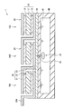
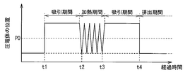
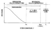
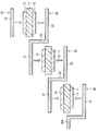
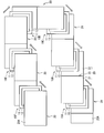
- FIG. 1 is a block diagram illustrating an overall configuration of a fuel cell system according to an embodiment of the present invention. It is sectional drawing showing the structural example of the electric power generation part shown in FIG. It is a top view showing the structural example of the electric power generation part shown in FIG. It is sectional drawing which represented the detailed structure of the fuel pump typically. It is a timing diagram showing the relationship between the position of a piezoelectric material and the operating state of a fuel pump. It is a characteristic view for demonstrating the outline
- FIG. 1 shows an overall configuration of a fuel cell system (fuel cell system 5) according to an embodiment of the present invention.
- the fuel cell system 5 supplies power for driving the load 6 via the output terminals T2 and T3.
- the fuel cell system 5 includes a fuel cell 1, a current detector 31, a voltage detector 32, a booster circuit 33, a secondary battery 34, and a controller 35.
- the fuel cell 1 includes a power generation unit 10, a fuel tank 40, and a fuel pump 42. The detailed configuration of the fuel cell 1 will be described later.
- the power generation unit 10 is a direct methanol type power generation unit that generates power by a reaction between methanol and an oxidant gas (for example, oxygen), and includes a plurality of unit cells having a positive electrode (oxygen electrode) and a negative electrode (fuel electrode). It consists of The detailed configuration of the power generation unit 10 will be described later.
- an oxidant gas for example, oxygen
- the fuel tank 40 contains liquid fuel (for example, methanol or aqueous methanol solution) necessary for power generation.
- liquid fuel for example, methanol or aqueous methanol solution
- the fuel pump 42 is a pump for pumping the liquid fuel accommodated in the fuel tank 40 and supplying (transporting) the liquid fuel to the power generation unit 10 side, and is capable of adjusting the fuel supply amount.
- the fuel pump 42 is a piezoelectric pump. The operation of the fuel pump 42 (liquid fuel supply operation) is controlled by a control unit 35 described later. The detailed configuration of the fuel pump 42 will be described later.
- the current detection unit 31 is arranged between the positive electrode side of the power generation unit 10 and the connection point P1 on the connection line L1H, and detects the power generation current I1 of the power generation unit 10.
- the current detection unit 31 includes a resistor, for example. Such a current detection unit 31 may be disposed on the connection line L1L (between the negative electrode side of the power generation unit 10 and the connection point P2).
- the voltage detector 32 is arranged between the connection point P1 on the connection line L1H and the connection point P2 on the connection line L1L, and detects the power generation voltage V1 of the power generation unit 10.
- the voltage detection unit 32 includes a resistor, for example.
- the booster circuit 33 is disposed between the connection point P1 on the connection line L1H and the connection point P3 on the output line LO, and boosts the power generation voltage V1 (DC voltage) of the power generation unit 10 to generate a DC voltage. It is a voltage conversion part which produces
- the booster circuit 33 is constituted by, for example, a DC / DC converter.
- the secondary battery 34 is disposed between the connection point P3 on the output line LO and the connection point P4 on the ground line LG, and stores power based on the DC voltage V2 generated by the booster circuit 33. It is.
- the secondary battery 34 is composed of, for example, a lithium ion secondary battery.
- the control unit 35 supplies the liquid fuel by the fuel pump 42 based on the generated current (detected current) I1 detected by the current detector 31 and the generated voltage (detected voltage) V1 detected by the voltage detector 32. The amount is adjusted. Specifically, the control unit 35 adjusts the amount of liquid fuel supplied by the fuel pump 42 by controlling the vibration frequency f of a piezoelectric body (a piezoelectric body 422 described later) in the fuel pump 42. Yes.
- a control part 35 is comprised by the microcomputer etc., for example. The detailed operation of the control unit 35 will be described later.
- FIGS. 2 and 3 show configuration examples of the unit cells 10A to 10F in the power generation unit 10 in the fuel cell 1, and FIG. 2 corresponds to the cross-sectional configuration taken along the line II-II in FIG. To do.
- the unit cells 10A to 10F are arranged in, for example, 3 rows ⁇ 2 columns in the in-plane direction, and have a planar stacked structure in which a plurality of connection members 20 are electrically connected in series.
- a terminal 20A which is an extension of the connection member 20, is attached to the unit cells 10A and 10F.
- a fuel tank 40, a fuel pump 42, a nozzle 43, and a fuel vaporization unit 44 are provided below the unit cells 10A to 10F.
- Each of the unit cells 10A to 10F has a fuel electrode (a negative electrode, an anode electrode) 12 and an oxygen electrode 13 (a positive electrode, a cathode electrode) arranged to face each other with the electrolyte membrane 11 therebetween.
- a fuel electrode a negative electrode, an anode electrode
- an oxygen electrode 13 a positive electrode, a cathode electrode
- the electrolyte membrane 11 is made of, for example, a proton conductive material having a sulfonic acid group (—SO 3 H).
- proton conducting materials include polyperfluoroalkylsulfonic acid proton conducting materials (for example, “Nafion (registered trademark)” manufactured by DuPont), hydrocarbon proton conducting materials such as polyimide sulfonic acid, or fullerene proton conducting materials. Is mentioned.
- the fuel electrode 12 and the oxygen electrode 13 have a configuration in which a catalyst layer containing a catalyst such as platinum (Pt) or ruthenium (Ru) is formed on a current collector made of, for example, carbon paper.
- the catalyst layer is made of, for example, a dispersion in which a carrier such as carbon black carrying a catalyst is dispersed in a polyperfluoroalkylsulfonic acid proton conductive material or the like.
- an air supply pump (not shown) may be connected to the oxygen electrode 13 or communicate with the outside through an opening (not shown) provided in the connection member 20 to supply air, that is, oxygen by natural ventilation. You may come to be.
- the connecting member 20 has a bent portion 23 between the two flat portions 21 and 22.
- the connecting member 20 is in contact with the fuel electrode 12 of one unit cell (for example, 10A) in one flat portion 21 and in the other flat portion 22.
- Adjacent to the oxygen electrode 13 of the adjacent unit cell (for example, 10B), the two adjacent unit cells (for example, 10A and 10B) are electrically connected in series, and are generated in each of the unit cells 10A to 10F. It also has a function as a current collector for collecting electricity.
- Such a connection member 20 has, for example, a thickness of 150 ⁇ m and is made of copper (Cu), nickel (Ni), titanium (Ti), or stainless steel (SUS), such as gold (Au) or platinum (Pt). It may be plated with.
- the connecting member 20 has openings (not shown) for supplying fuel and air to the fuel electrode 12 and the oxygen electrode 13, respectively.
- the connecting member 20 is made of mesh such as expanded metal, punching metal, or the like. It is configured.
- the bent portion 23 may be bent in advance according to the thickness of the unit cells 10A to 10F, or in the manufacturing process when the connecting member 20 has flexibility such as a mesh having a thickness of 200 ⁇ m or less. It may be formed by bending.
- Such a connecting member 20 is formed by, for example, screwing a sealing material (not shown) such as PPS (polyphenylene sulfide) or silicone rubber provided around the electrolyte membrane 11 to the connecting member 20. It is joined to the unit cells 10A to 10F.
- the fuel tank 40 includes, for example, a container (for example, a plastic bag) whose volume changes without bubbles or the like even when the liquid fuel 41 increases or decreases, and a rectangular parallelepiped case (structure) that covers the container. Has been.
- the fuel tank 40 is provided with a fuel pump 42 for sucking the liquid fuel 41 in the fuel tank 40 and discharging it from the nozzle 43 near the center.
- the fuel vaporization unit 44 supplies gaseous fuel to the power generation unit 10 (unit cells 10A to 10F) by vaporizing the liquid fuel supplied by the fuel pump 42. That is, the fuel vaporization unit 44 is arranged between the fuel pump 42 and the power generation unit 10.
- a fuel vaporization part 44 promotes the diffusion of fuel on a plate (not shown) made of a highly rigid resin material such as a metal or alloy including, for example, stainless steel or aluminum, or a cycloolefin copolymer (COC).
- a diffusion unit (not shown) is provided.
- an inorganic porous material such as alumina, silica, titanium oxide, or a resin porous material can be used.
- the nozzle 43 is a fuel ejection port that is transported by a flow path (not shown) of the fuel pump 42, and ejects fuel toward a diffusion portion provided on the surface of the fuel vaporization portion 44. Yes. Thereby, the fuel transported to the fuel vaporization unit 44 is diffused and vaporized and supplied to the power generation unit 10 (unit cells 10A to 10F).
- the nozzle 43 has a diameter of, for example, 0.1 mm to 0.5 mm.
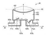
- FIG. 4 schematically shows a cross-sectional configuration of the fuel pump 42.
- the fuel pump 42 includes a pump chamber 420 formed by a container 421 and a piezoelectric body 422, a pair of flow paths 423a and 423b as pipes connecting the fuel tank 40 to the nozzle 43, and a pair of check valves 425a and 425b. It is comprised by. As shown by the arrows in FIG. 4, the fuel pump 42 utilizes the bending deformation of the piezoelectric body 422 functioning as an actuator and the opening / closing operations of the check valves 425a and 425b, and the arrows Pin and Pout in the drawing. 4 is a piezoelectric pump that feeds liquid fuel 41 from the fuel tank 40 side to the fuel vaporization unit 44 side.
- the piezoelectric body 422 forms the upper surface of the pump chamber 420 and includes a piezoelectric element such as lead zirconate titanate (PZT).
- the piezoelectric body 422 has a property of generating heat when deformed. In particular, when the piezoelectric body 422 is vibrated in the vicinity of its mechanical resonance frequency (natural frequency) f E (for example, about 45 kHz), a very large bending deformation is generated, and heat generation due to this is increased. Yes.
- the check valve 425 a is provided at the suction port 424 a portion in the pump chamber 420.
- the suction port 424a is provided at a connection portion between the pump chamber 420 and the flow path 423a on the fuel tank 40 side.
- the check valve 425 b is provided at the discharge port 424 b portion in the pump chamber 420.
- the discharge port 424b is provided at a connection portion between the pump chamber 420 and the flow path 423b on the fuel vaporization unit 44 side.
- the two check valves 425a and 425b are provided on the inflow side and the outflow side of the liquid fuel 41 so that the unidirectionality of the flow of the liquid fuel 41 is maintained.
- These check valves 425a and 425b have a property that when the driving frequency thereof becomes higher, the opening / closing operation of the valves gradually cannot catch up accordingly, and eventually the fuel cannot be supplied.
- the suction period of the liquid fuel 41 (for example, the timings t1 to t2, t3 to t4) is changed according to the position of the piezoelectric body 422.
- Period and a discharge period (for example, a period after timing t4) of the liquid fuel 41 are provided.
- the supply amount of the liquid fuel 41 can be adjusted in accordance with a change in the vibration frequency f of the piezoelectric body 422 and a change in the fuel supply amount or fuel supply cycle ⁇ t per operation (see FIG. 6). It is like that.
- the upper limit frequency (threshold frequency f TH ; for example, about 40 Hz) that allows the check valves 425a and 425b to be opened and closed.
- f TH the mechanical resonance frequency of the piezoelectric body 422 described above.
- control unit 35 controls the vibration frequency f of the piezoelectric body 422 to be in the vicinity of the mechanical resonance frequency f E (preferably, the resonance frequency f E ) of the piezoelectric body 422 in a predetermined case. It has become. Specifically, the control unit 35 periodically or when the temperature of the fuel vaporization unit 44 becomes lower than a predetermined threshold temperature (for example, (the temperature of the power generation unit 10 ⁇ 5 ° C.)) vibration frequency f of the piezoelectric element 422 is controlled to be a frequency near the resonance frequency f E.
- a predetermined threshold temperature for example, (the temperature of the power generation unit 10 ⁇ 5 ° C.
- the liquid fuel 41 in the fuel pump 42 is heated by the vibration of the piezoelectric body 422, for example, during the heating period (period t2 to t3) shown in FIG.
- the liquid fuel 41 is supplied to the fuel vaporization unit 44.
- the control is performed when the upper limit frequencies (threshold frequencies f TH ) of the check valves 425a and 425b are values in the audible frequency region.
- the vibration frequency f of the piezoelectric body 422 may be controlled to be higher than the threshold frequency fTH in the audible frequency region. That is, the vibration frequency f of the piezoelectric body 422 may satisfy the following expression (2). f TH ⁇ f ⁇ fmax (2)
- the fuel tank 40 is detachable, the fuel tank 40 is exchanged or liquid fuel is injected into the fuel tank 40. Also, it is when power generation is abnormal in the power generation unit 10 or when a precursor is detected (for example, when an oxygen deficiency state is detected).
- the vibration frequency f of the piezoelectric body 422 is higher than the upper limit frequency (threshold frequency f TH ).
- the opening / closing operations of 425a and 425b are stopped, and the fuel supply operation by the fuel pump 42 is also stopped.
- the vibration frequency f of the piezoelectric body 422 is also in the audible frequency region, an audible sound is generated by the vibration of the piezoelectric body 422. Therefore, a sound effect or the like can be emitted to the user in a predetermined case as described above without separately providing a member such as a speaker. Further, since the fuel supply operation is stopped, it is possible to generate only sound effects without affecting the original power generation operation in the power generation unit 10.
- the fuel cell system 5 of the present embodiment can be manufactured as follows, for example.
- the fuel electrode 12 and the oxygen electrode 13 are joined to the electrolyte membrane 11 by thermocompression bonding the electrolyte membrane 11 made of the above-described material between the fuel electrode 12 and the oxygen electrode 13 made of the above-described material, Unit cells 10A to 10F are formed.
- a connecting member 20 made of the above-described material is prepared, and as shown in FIGS. 8 and 9, six unit cells 10A to 10F are arranged in 3 rows ⁇ 2 columns and electrically connected by the connecting member 20. Connect in series.
- a sealing material (not shown) made of the above-described material is provided around the electrolyte membrane 11, and the sealing material is fixed to the bent portion 23 of the connecting member 20 by screwing.
- the fuel cell 1 Form. Then, by arranging the fuel tank 40 in which the liquid fuel 41 is accommodated and the fuel pump 42 and the nozzle 43 are provided on the fuel electrode 12 side of the connected unit cells 10A to 10F, the fuel cell 1 Form. Then, the current detector 31, voltage detector 32, booster circuit 33, secondary battery 34, and controller 35 described above are attached to the fuel cell 1 in electrical parallel connection as shown in FIG. . Thus, the fuel cell system 5 shown in FIGS. 1 to 4 is completed.
- the liquid fuel 41 contained in the fuel tank 40 is pumped up by the fuel pump 42, so that the liquid fuel 41 flows into the flow path 423 a, the check valve 425 a, the pump chamber 420, the check valve 425 b and It passes through the flow path 423b in this order and reaches the fuel vaporization unit 44.
- the fuel vaporization part 44 if liquid fuel is ejected by the nozzle 43, it will be spread
- the liquid fuel 41 is naturally vaporized, and the gaseous fuel is supplied to the power generation unit 10 (specifically, the fuel electrodes 12 of the unit cells 10A to 10F).
- air oxygen
- oxygen oxygen
- air oxygen
- an air supply pump not shown
- the reaction shown in the following formula (3) occurs, and hydrogen ions and electrons are generated.
- the hydrogen ions reach the fuel electrode 12 through the electrolyte membrane 11, and the reaction shown in the following formula (4) occurs in the fuel electrode 12 to generate water and carbon dioxide. Therefore, the fuel cell 1 as a whole undergoes the reaction shown in the following formula (5), and power is generated.
- the generated voltage (DC voltage) V1 based on the generated current I1 is boosted (voltage converted) by the booster circuit 33 to become a DC voltage V2.
- the DC voltage V2 is supplied to the secondary battery 34 or a load (for example, an electronic device main body).
- the secondary battery 34 is charged based on this voltage, while the DC voltage V2 is supplied to the load 6 through the output terminals T2 and T3. In this case, the load 6 is driven and a predetermined operation is performed.
- the control unit 35 controls the fuel supply amount or fuel supply period ⁇ t per operation and the vibration frequency f of the piezoelectric body 422 in the fuel pump 42, and the fuel supply is accordingly performed. The amount is adjusted.
- the vibration frequency f of the piezoelectric body 422 is the mechanical resonance frequency of the piezoelectric body 422. It is controlled to be around f E. Further, the upper limit frequency (threshold frequency f TH ) at which the check valves 425 a and 425 b can be opened and closed is lower than the mechanical resonance frequency f E of the piezoelectric body 422.
- the check valve 425a when the vibration frequency f of the piezoelectric element 422 is in the vicinity of the resonance frequency f E, the check valve 425a, and stops the opening and closing operation of the 425b, also stops the fuel supply operation by the fuel pump 42. Further, the liquid fuel 41 in the fuel pump 42 is heated by the vibration of the piezoelectric body 422. That is, it is possible to heat only the piezoelectric body 422 as an actuator with almost no liquid feeding. Therefore, since the piezoelectric body 422 is in the vicinity of the pump chamber 420, only the liquid fuel 41 in the pump chamber 420 is selectively and efficiently heated.
- the liquid fuel 41 heated in this way is supplied to the fuel vaporization unit 44, whereby the temperature decrease due to the vaporization heat is suppressed in the fuel vaporization unit 44.
- the amount of heat generated by the vibration with the vibration frequency f near the resonance frequency f E is substantially equal to the heat of vaporization of the liquid fuel 41. This is because if such a heat quantity is generated, a temperature decrease due to the heat of vaporization in the fuel vaporization section 44 is completely prevented.
- FIG. 10 shows a fuel pump in which the upper limit frequency (threshold frequency f TH ) of the check valves 425a and 425b is about 40 Hz, the resonance frequency f E of the piezoelectric body 422 is about 45 kHz, and the rated drive voltage is 12 Vpp. 42, an AC voltage (AC frequency: 100 kHz, 1 Vpp) is applied, and sweeping is performed such as (100 kHz ⁇ 1 kHz ⁇ 100 kHz ⁇ ...) ) Shows the measurement results when observing changes in temperature and impedance.
- the upper limit frequency (threshold frequency f TH ) of the check valves 425a and 425b is about 40 Hz
- the resonance frequency f E of the piezoelectric body 422 is about 45 kHz
- the rated drive voltage is 12 Vpp. 42
- an AC voltage AC frequency: 100 kHz, 1 Vpp
- sweeping such as (100 kHz ⁇ 1 kHz ⁇ 100 kHz
- the upper limit frequency (threshold frequency f TH ) at which the check valves 425a and 425b can be opened and closed is lower than the mechanical resonance frequency f E of the piezoelectric body 422. and sets so that, in a predetermined case, the vibration frequency f of the piezoelectric element 422 is set to be near the resonance frequency f E, while stopping the fuel supply operation by the fuel pump 42, the vibration of the piezoelectric element 422
- the liquid fuel 41 of the fuel pump 42 can be heated, and the heated liquid fuel 41 can be supplied to the fuel vaporization unit 44.
- the power generation characteristics of the power generation unit 10 are not impaired as in the related art. Therefore, the flooding phenomenon of the fuel vaporization unit 44 can be suppressed without impairing the power generation characteristics.
- the fuel pump 42 can be used for direct heating without separately providing a member such as a heater, the member cost can be reduced. In addition, it contributes to space saving and simplifies the control circuit.
- the piezoelectric 422 when the amount of heat generated by the vibration of the vibration frequency f of the frequency near the resonance frequency f E was set to be substantially equal to the heat of vaporization of the liquid fuel 41, the temperature drop due to vaporization heat in the fuel vaporization section 44 Is completely prevented. Therefore, water condensation (flooding phenomenon) in the fuel vaporization unit 44 can be completely avoided.
- the vibration frequency f of the piezoelectric body 422 is within the audible frequency range in a predetermined case.
- the frequency f TH is made higher (when the vibration frequency f of the piezoelectric body 422 satisfies the above expression (2)), a member such as a speaker is not separately provided, and the power generation unit 10 A sound effect or the like can be emitted to the user in a predetermined case without affecting the original power generation operation.
- the power generation unit 10 includes six unit cells electrically connected in series to each other has been described.
- the number of unit cells is not limited to this.
- the power generation unit 10 may be configured with one unit cell, or may be configured with two or more arbitrary unit cells.
- the air supply to the oxygen electrode 13 is natural ventilation, but it may be forcibly supplied using a pump or the like. In that case, oxygen or a gas containing oxygen may be supplied instead of air.
- the fuel cell system of the present invention can be suitably used for portable electronic devices such as a mobile phone, an electrophotographic machine, an electronic notebook, or a PDA (Personal Digital Assistants).
- portable electronic devices such as a mobile phone, an electrophotographic machine, an electronic notebook, or a PDA (Personal Digital Assistants).
Landscapes
- Life Sciences & Earth Sciences (AREA)
- Engineering & Computer Science (AREA)
- Manufacturing & Machinery (AREA)
- Sustainable Development (AREA)
- Sustainable Energy (AREA)
- Chemical & Material Sciences (AREA)
- Chemical Kinetics & Catalysis (AREA)
- Electrochemistry (AREA)
- General Chemical & Material Sciences (AREA)
- Fuel Cell (AREA)
Abstract
Description
fTH <fE ……(1)
fTH <f<fmax ……(2)
CH3OH+H2O→ CO2+6H++6e- ……(3)
6H++(3/2)O2+6e-→ 3H2O ……(4)
CH3OH+(3/2)O2→ CO2+2H2O ……(5)
Claims (11)
- 燃料および酸化剤ガスの供給により発電を行う発電部と、
圧電体および逆止弁を含んで構成され、前記発電部側へ液体燃料を供給する圧電ポンプ部と、
前記圧電ポンプ部により供給された液体燃料を気化させることによって、気体燃料を前記発電部へ供給する燃料気化部と、
前記圧電体の振動周波数を制御することによって、前記圧電ポンプ部による液体燃料の供給量を調整する制御部と
を備え、
前記逆止弁の開閉動作が可能な上限周波数が、前記圧電体の機械的な共振周波数よりも低くなっており、
前記制御部は、所定の場合に、前記圧電体の振動周波数が前記共振周波数付近となるように制御する
燃料電池システム。 - 前記圧電体において前記共振周波数付近の振動周波数の振動により生ずる熱量が、前記液体燃料の気化熱と略等しい
請求項1に記載の燃料電池システム。 - 前記燃料気化部が、前記圧電ポンプ部と前記発電部との間に配置されている
請求項1に記載の燃料電池システム。 - 前記制御部は、定期的に、前記圧電体の振動周波数が前記共振周波数付近となるように制御を行う
請求項1に記載の燃料電池システム。 - 前記制御部は、前記燃料気化部の温度が所定の閾値温度よりも低くなったときに、前記圧電体の振動周波数が前記共振周波数付近となるように制御を行う
請求項1に記載の燃料電池システム。 - 前記共振周波数が、可聴周波数領域の上限値よりも高くなっている
請求項1に記載の燃料電池システム。 - 前記上限周波数が、可聴周波数領域内の値となっており、
前記制御部は、所定の場合に、前記圧電体の振動周波数が、可聴周波数領域内において前記上限周波数よりも高くなるように制御する
請求項1ないし請求項6のいずれか1項に記載の燃料電池システム。 - 前記液体燃料を収容すると共に着脱可能な燃料タンクを備え、
前記制御部は、前記燃料タンクの交換時、または、前記燃料タンクへの液体燃料の注入時に、前記圧電体の振動周波数が可聴周波数領域内において前記上限周波数よりも高くなるように制御を行う
請求項7に記載の燃料電池システム。 - 前記制御部は、前記発電部における発電異常時、または、その前兆の検出時に、前記圧電体の振動周波数が可聴周波数領域内において前記上限周波数よりも高くなるように制御を行う
請求項7に記載の燃料電池システム。 - 前記液体燃料を収容する燃料タンクを備えた
請求項1に記載の燃料電池システム。 - 燃料電池システムを備え、
前記燃料電池システムは、
燃料および酸化剤ガスの供給により発電を行う発電部と、
圧電体および逆止弁を含んで構成され、前記発電部側へ液体燃料を供給する圧電ポンプ部と、
前記圧電ポンプ部により供給された液体燃料を気化させることによって、気体燃料を前記発電部へ供給する燃料気化部と、
前記圧電体の振動周波数を制御することによって、前記圧電ポンプ部による液体燃料の供給量を調整する制御部と
を有し、
前記逆止弁の開閉動作が可能な上限周波数が、前記圧電体の機械的な共振周波数よりも低くなっており、
前記制御部は、所定の場合に、前記圧電体の振動周波数が前記機械的な共振周波数付近となるように制御する
電子機器。
Priority Applications (2)
| Application Number | Priority Date | Filing Date | Title |
|---|---|---|---|
| US13/059,011 US20110136032A1 (en) | 2008-08-21 | 2009-07-29 | Fuel cell system and electronic device |
| CN2009801315985A CN102124596B (zh) | 2008-08-21 | 2009-07-29 | 燃料电池系统和电子装置 |
Applications Claiming Priority (2)
| Application Number | Priority Date | Filing Date | Title |
|---|---|---|---|
| JP2008-212830 | 2008-08-21 | ||
| JP2008212830A JP5228697B2 (ja) | 2008-08-21 | 2008-08-21 | 燃料電池システムおよび電子機器 |
Publications (1)
| Publication Number | Publication Date |
|---|---|
| WO2010021232A1 true WO2010021232A1 (ja) | 2010-02-25 |
Family
ID=41707110
Family Applications (1)
| Application Number | Title | Priority Date | Filing Date |
|---|---|---|---|
| PCT/JP2009/063506 Ceased WO2010021232A1 (ja) | 2008-08-21 | 2009-07-29 | 燃料電池システムおよび電子機器 |
Country Status (4)
| Country | Link |
|---|---|
| US (1) | US20110136032A1 (ja) |
| JP (1) | JP5228697B2 (ja) |
| CN (1) | CN102124596B (ja) |
| WO (1) | WO2010021232A1 (ja) |
Families Citing this family (4)
| Publication number | Priority date | Publication date | Assignee | Title |
|---|---|---|---|---|
| JP4956589B2 (ja) * | 2009-08-07 | 2012-06-20 | 株式会社東芝 | 燃料電池 |
| US20150315981A1 (en) * | 2014-05-02 | 2015-11-05 | General Electric Company | Fuel supply system |
| JP6299585B2 (ja) * | 2014-12-22 | 2018-03-28 | トヨタ自動車株式会社 | 燃料電池システム |
| CN112258805A (zh) * | 2020-11-06 | 2021-01-22 | 郑州大学 | 一种基于图像识别气化电解液判断电池安全预警装置 |
Citations (7)
| Publication number | Priority date | Publication date | Assignee | Title |
|---|---|---|---|---|
| JP2001015130A (ja) * | 1999-06-29 | 2001-01-19 | Toshiba Corp | 燃料電池 |
| JP2003120541A (ja) * | 2001-10-19 | 2003-04-23 | Matsushita Electric Ind Co Ltd | 小型ポンプ及びその駆動方法 |
| JP2003317756A (ja) * | 2002-04-23 | 2003-11-07 | Seiko Epson Corp | 燃料電池システムおよびその駆動方法 |
| JP2004127671A (ja) * | 2002-10-01 | 2004-04-22 | Nec Corp | 燃料電池システム、燃料電池システムを用いた携帯型電気機器、および燃料電池の駆動方法 |
| JP2007091499A (ja) * | 2005-09-27 | 2007-04-12 | Casio Comput Co Ltd | 反応装置 |
| WO2007110941A1 (ja) * | 2006-03-29 | 2007-10-04 | Fujitsu Limited | 燃料電池 |
| JP2008506240A (ja) * | 2004-07-08 | 2008-02-28 | ダイレクト メタノール ヒューエル セル コーポレイション | 燃料電池カートリッジおよび燃料供給システム |
Family Cites Families (4)
| Publication number | Priority date | Publication date | Assignee | Title |
|---|---|---|---|---|
| JP2003178783A (ja) * | 2001-10-02 | 2003-06-27 | Ngk Insulators Ltd | 燃料電池発電装置 |
| JP2003346846A (ja) * | 2002-05-22 | 2003-12-05 | Seiko Epson Corp | 燃料電池装置 |
| JP4288052B2 (ja) * | 2002-09-04 | 2009-07-01 | カルソニックカンセイ株式会社 | 凍結し得る液体の貯留タンク |
| US7312554B2 (en) * | 2004-04-02 | 2007-12-25 | Adaptivenergy, Llc | Piezoelectric devices and methods and circuits for driving same |
-
2008
- 2008-08-21 JP JP2008212830A patent/JP5228697B2/ja not_active Expired - Fee Related
-
2009
- 2009-07-29 CN CN2009801315985A patent/CN102124596B/zh not_active Expired - Fee Related
- 2009-07-29 US US13/059,011 patent/US20110136032A1/en not_active Abandoned
- 2009-07-29 WO PCT/JP2009/063506 patent/WO2010021232A1/ja not_active Ceased
Patent Citations (7)
| Publication number | Priority date | Publication date | Assignee | Title |
|---|---|---|---|---|
| JP2001015130A (ja) * | 1999-06-29 | 2001-01-19 | Toshiba Corp | 燃料電池 |
| JP2003120541A (ja) * | 2001-10-19 | 2003-04-23 | Matsushita Electric Ind Co Ltd | 小型ポンプ及びその駆動方法 |
| JP2003317756A (ja) * | 2002-04-23 | 2003-11-07 | Seiko Epson Corp | 燃料電池システムおよびその駆動方法 |
| JP2004127671A (ja) * | 2002-10-01 | 2004-04-22 | Nec Corp | 燃料電池システム、燃料電池システムを用いた携帯型電気機器、および燃料電池の駆動方法 |
| JP2008506240A (ja) * | 2004-07-08 | 2008-02-28 | ダイレクト メタノール ヒューエル セル コーポレイション | 燃料電池カートリッジおよび燃料供給システム |
| JP2007091499A (ja) * | 2005-09-27 | 2007-04-12 | Casio Comput Co Ltd | 反応装置 |
| WO2007110941A1 (ja) * | 2006-03-29 | 2007-10-04 | Fujitsu Limited | 燃料電池 |
Also Published As
| Publication number | Publication date |
|---|---|
| CN102124596B (zh) | 2013-11-06 |
| US20110136032A1 (en) | 2011-06-09 |
| JP5228697B2 (ja) | 2013-07-03 |
| JP2010049927A (ja) | 2010-03-04 |
| CN102124596A (zh) | 2011-07-13 |
Similar Documents
| Publication | Publication Date | Title |
|---|---|---|
| CN102119460B (zh) | 燃料电池系统和电子装置 | |
| WO2004032271A1 (ja) | 燃料電池の運転方法および燃料電池およびこれを搭載した携帯機器および携帯電話機 | |
| US8264123B2 (en) | Piezoelectric vibration device system and electronics apparatus | |
| JP5228697B2 (ja) | 燃料電池システムおよび電子機器 | |
| JP5344223B2 (ja) | 燃料電池システムおよび電子機器 | |
| US20110136031A1 (en) | Fuel cell system and electronic device | |
| JP5344219B2 (ja) | 燃料電池システムおよび電子機器 | |
| JP5360452B2 (ja) | 燃料電池および電子機器 | |
| JP5344218B2 (ja) | 燃料電池システムおよび電子機器 | |
| JP2010251317A (ja) | 燃料電池、燃料電池システムおよび電子機器 | |
| CN101803096B (zh) | 燃料电池系统以及电子装置 | |
| JP2010239701A (ja) | 燃料電池システム及び圧電ポンプ装置 | |
| TW200933967A (en) | Piezoelectric proton exchange membrane fuel cell with changeable channel | |
| US20120034543A1 (en) | Fuel cell separator, and fuel cell stack and fuel cell system using same | |
| JP2006202509A (ja) | 携帯型コンピュータ | |
| JP2010244919A (ja) | 燃料電池システム、燃料電池システムの制御方法 | |
| JP2010238408A (ja) | 燃料電池システム及びバルブ装置 | |
| JP2008218032A (ja) | 燃料電池システム及び電子機器 | |
| JP2010033898A (ja) | 燃料電池システム及び電子機器 | |
| JP2006222062A (ja) | 携帯機器用電池駆動システム | |
| JP2010170732A (ja) | 燃料電池システム及び電子機器 | |
| JP2006049086A (ja) | 燃料電池モジュール | |
| JP2010232074A (ja) | 燃料電池システムおよび電子機器 | |
| JP2010108840A (ja) | 燃料電池およびこれに用いる電極ならびに電子機器 |
Legal Events
| Date | Code | Title | Description |
|---|---|---|---|
| WWE | Wipo information: entry into national phase |
Ref document number: 200980131598.5 Country of ref document: CN |
|
| 121 | Ep: the epo has been informed by wipo that ep was designated in this application |
Ref document number: 09808168 Country of ref document: EP Kind code of ref document: A1 |
|
| WWE | Wipo information: entry into national phase |
Ref document number: 13059011 Country of ref document: US |
|
| NENP | Non-entry into the national phase |
Ref country code: DE |
|
| 122 | Ep: pct application non-entry in european phase |
Ref document number: 09808168 Country of ref document: EP Kind code of ref document: A1 |