WO2009148136A1 - 連結釘 - Google Patents
連結釘 Download PDFInfo
- Publication number
- WO2009148136A1 WO2009148136A1 PCT/JP2009/060287 JP2009060287W WO2009148136A1 WO 2009148136 A1 WO2009148136 A1 WO 2009148136A1 JP 2009060287 W JP2009060287 W JP 2009060287W WO 2009148136 A1 WO2009148136 A1 WO 2009148136A1
- Authority
- WO
- WIPO (PCT)
- Prior art keywords
- nail
- row
- nails
- band
- magazine
- Prior art date
- Legal status (The legal status is an assumption and is not a legal conclusion. Google has not performed a legal analysis and makes no representation as to the accuracy of the status listed.)
- Ceased
Links
Images


Classifications
-
- B—PERFORMING OPERATIONS; TRANSPORTING
- B25—HAND TOOLS; PORTABLE POWER-DRIVEN TOOLS; MANIPULATORS
- B25C—HAND-HELD NAILING OR STAPLING TOOLS; MANUALLY OPERATED PORTABLE STAPLING TOOLS
- B25C1/00—Hand-held nailing tools; Nail feeding devices
- B25C1/001—Nail feeding devices
- B25C1/005—Nail feeding devices for rows of contiguous nails
-
- F—MECHANICAL ENGINEERING; LIGHTING; HEATING; WEAPONS; BLASTING
- F16—ENGINEERING ELEMENTS AND UNITS; GENERAL MEASURES FOR PRODUCING AND MAINTAINING EFFECTIVE FUNCTIONING OF MACHINES OR INSTALLATIONS; THERMAL INSULATION IN GENERAL
- F16B—DEVICES FOR FASTENING OR SECURING CONSTRUCTIONAL ELEMENTS OR MACHINE PARTS TOGETHER, e.g. NAILS, BOLTS, CIRCLIPS, CLAMPS, CLIPS OR WEDGES; JOINTS OR JOINTING
- F16B15/00—Nails; Staples
- F16B15/08—Nails; Staples formed in integral series but easily separable
Definitions
- the present invention relates to a nailing machine in which a plurality of nails arranged in parallel so that nail shaft portions are parallel are connected by a synthetic resin connecting band, and two connecting nails can be loaded in two rows.
- the present invention relates to a connecting nail used for a double loading magazine.
- a general nailing machine is equipped with a magazine for loading only one connecting nail, but one with a double loading magazine for loading two connecting nails is also known (see Patent Document 1). ).
- the connecting nail loaded in the double loading magazine is a stick-type connecting nail formed by connecting a plurality of nails straight (straight).
- two connecting nails are arranged so as to overlap each other.
- One end of the magazine is opened so that the tip of the first row of connecting nails is fed to the nail injection nose, and the second row of connecting nails is spring-biased toward the first row of connecting nails. Yes. After all the first row connecting nails are driven, the second row connecting nails move to the position of the first row connecting nails.
- the connecting nail provided in the magazine is cooled after pressing a paper tape (connecting band) coated with thermoplastic adhesive such as hot melt on one side against the heated nail shafts arranged in parallel to each other. It was manufactured by doing.
- the paper connection band is strongly bonded to the nail shaft, even if the nail connection band driven by nail driving breaks and separates from the next nail connection band, it is made of paper.
- the connecting band is directly bonded to the nail shaft and is driven into the material to be driven (wood). Therefore, a broken piece separated from the coupling band enters between the nail shaft and the wood, and a gap is generated between the nail shaft and the wood due to the broken broken piece, and the pulling-out strength of the nail is likely to be lowered.
- the magazine is loaded with the nail heads of the second row of connecting nails in contact with the connecting band of the first row of connecting nails. For this reason, when the contact friction between the first row of connecting nails and the second row of connecting nails that are in contact with the connecting nails is large, The nail feed of the connecting nail in the first row is obstructed.
- the connection band is made of paper, and the nail head and the paper (connection band) are difficult to slip from each other. Therefore, the connecting nail in the second row tends to serve as a brake against the feeding of the connecting nail in the first row, and the pusher for nail feeding has to be enlarged.
- the present invention provides a connecting nail that does not deteriorate the pull-out strength of the nail, is less likely to crack the end of the wood, and can be smoothly fed into the nail.
- the connection nail includes a plurality of nails and a connection band for connecting the upper and lower parts of the plurality of nails, respectively, the connection band is made of a synthetic resin, Surrounding each nail, one side surface of the connecting band is formed flat, the flat side surface is provided at a position close to the nail head, and the two connecting nails can be loaded in two rows Served in a double loading magazine for nailers.
- reinforcing ribs may be integrally formed between the adjacent nails in the connecting band.
- the first row and the second row of connecting nails hit the nail head of the other connecting nail on the flat side surface of the upper connecting band of one of the connecting nails. In this way, the magazine may be loaded.
- a notch may be formed in the center of each reinforcing rib of the lower connecting band.
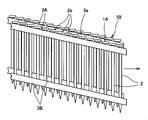
- FIG. 1A is a side view of one of the connecting nails according to the present invention.
- FIG. 1B is a side view of the other side of the connecting nail according to the present invention.
- FIG. 2 is a partially enlarged sectional view taken along line XX in FIG. 1B.
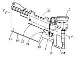
- FIG. 3 is a side view showing an embodiment of the connecting nail supply mechanism of the present invention.
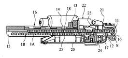
- FIG. 4 is a cross-sectional plan view showing a state in which two connecting nails 1 are loaded along line YY in FIG.
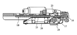
- FIG. 5 is a cross-sectional plan view similar to FIG. 2 with the second row of connecting nails moved to the first row.
- FIG. 6 is a side view showing a state where two connecting nails are loaded in a magazine.
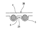
- FIG. 7 is an enlarged cross-sectional plan view of another form of the lower connecting band.
- the connecting nail 1 is configured by connecting a plurality of nails 2 by a connecting band 3.
- the connecting nail 1 is provided in a double loading magazine for a nailing machine in which two connecting nails 1 can be loaded in two rows.
- the connecting nail 1 is configured by connecting the upper and lower portions of a large number of nails 2 arranged in parallel with a connecting band 3.
- the connecting band 3 is made of synthetic resin, and an enclosing portion 5 is formed on one side of the band-shaped body 4 at a certain interval to enclose the nail shaft portion 2a of the nail.
- a reinforcing rib 6 is formed between the surrounding parts 5 of the two adjacent nails 2.
- the reinforcing rib 6 is formed integrally with the band-shaped main body 4 and the surrounding portion 5.
- the upper connecting band 3A is provided at a position close to the nail head 2b.
- the upper and lower connecting bands 3A and 3B are arranged in parallel, and a large number of nails 2 are arranged in parallel so as to obliquely intersect the connecting band. What is necessary is just to weld another connection band from the top, press from the upper part, and weld an upper and lower connection band. It is preferable to heat the whole before pressing. At this time, the surrounding portion 5 surrounds the nail shaft portion 2a so as to be tightened.
- connection band 3 is formed flat by the band-shaped body 4, and the reinforcing rib 6 is integrally formed between the adjacent nails 2.
- the nose portion 10 attached to the lower part of the housing of the nail driver has a nail injection port 11.
- the nail ejection port 11 slidably guides a driver driven by a striking cylinder mechanism (not shown).
- the nose portion 10 is further formed with an opening 12 for introducing a nail into the nail injection port 11 and a fixed guide wall 13 continuous with a side edge of the opening 12.
- One side surface of the fixed guide wall 13 is a fixed guide surface 14 for supplying the connecting nail 1 into the nail injection port 11.
- a double loading magazine 16 is formed behind the fixed guide wall 13, and the double loading magazine 16 includes a connecting nail support surface 15 that is flush with the fixed guide surface 14 and extends rearward.
- An opening / closing guide member 17 is provided to face the fixed guide surface 14 of the fixed guide wall 13.
- the open / close guide member 17 is supported by the nose portion 10 so as to be openable and closable by a pivotal support shaft 8 arranged in parallel with the nail injection port 11.
- the open / close guide member 17 forms a part of the nail injection port 11 of the nose portion 10 in the closed position, and forms a nail supply path 18 of the connecting nail 1 between the fixed guide surface 14.
- a magazine cover 20 is provided on the rear side of the opening / closing guide member 17 in the supply direction so as to be opened and closed.
- the connecting nail 1 is loaded into the nail supply path 18 by opening the opening / closing guide member 17 and the magazine cover 20.
- the connecting nail 1B in the second row is stacked and loaded on the connecting nail 1A in the first row.
- the connection nail 1B in the second row is one step higher than the connection nail 1A in the first row, and the nail head 2b of the connection nail 1A in the first row is the second. It arrange
- the back side of the fixed guide wall 13 of the nose portion 10 includes a nail feed member 21, a piston for reciprocating the nail feed member 21 along the nail supply direction, and a piston / cylinder mechanism that houses the piston.
- a feed drive mechanism 22 is provided.
- a part of the nail feeding member 21 advances from the opening formed in the fixed guide wall 13 into the nail supply path 18 and engages with each nail shaft portion 2 a of the connecting nail 1 arranged along the fixed guide surface 14. Then, the connecting nail 1 is supplied to the injection port of the nose portion 10.
- a check claw 23 for preventing the connecting nail 1 from moving rearward when the nail feed member 21 moves backward is provided on the back side of the fixed guide wall 13.
- a part of the check claw 23 advances into the nail supply path 18 through the opening and is arranged so as to be engageable with each nail shaft portion 2a of the connecting nail 1.
- the opening / closing guide member 17 is provided with a first pressing member 24 for pressing the second row of connecting nails 1B toward the fixed guide surface 14 side.
- the magazine cover 20 supports the first and second row of connecting nails 1A and 1B loaded along the connecting nail support surface 15 of the magazine 16 on the rear side of the opening / closing guide member 17 from the side. .
- the magazine cover 20 is provided with a second pressing member 25, and the second pressing member 25 biased in the direction of the connecting nail support surface 15 connects the second row connecting nail 1B and the first row connecting nail 1A. Press toward the nail support surface 15.
- the nail driving operation is performed in the state where the first and second row connecting nails 1A and 1B are loaded
- the nail disposed in the injection port 11 of the nose portion 10 is driven out by a driver (not shown).
- the feed drive mechanism 22 is operated to enter the nail supply path 18 and to retreat the nail feed member 21 engaged with the nail shaft portion of the connecting nail 1A at the front end position of the reciprocating stroke.
- the nail feed member 21 is retracted from the nail supply path 18 while being in contact with the nail shaft portion of the connecting nail 1A.
- the nail feed member 21 enters the nail supply path 18 again at the rear end position of the reciprocating stroke and engages with the nail shaft portion.
- the check claw 23 engages with the nail shaft portion of the first row connecting nail 1A to prevent the connecting nail 1A from moving backward.
- the nail feed member 21 is driven forward to feed the connecting nail 1 ⁇ / b> A in the first row toward the nose portion 10.
- connection nail 1A in the first row is sequentially driven and the last nail of the connection nail 1A in the first row moves forward from the foremost nail position of the connection nail 1B in the second row, the second row
- the connecting nail 1B is moved in the direction of the fixed guide surface 14 by the spring biasing force of the first and second pressing members 24, 25, and as shown in FIG. Moving.
- the check claw 23 is prevented from being engaged with the rear side of the leading nail of the connecting nail 1B in the second row and moving backward.
- the nail feed member 21 is engaged with the nail shaft of the second row of connecting nails 1B, and the second row of connecting nails 1B follows the first row of connecting nails 1A in the injection port 11. Are sequentially supplied.
- the leading nail of the connecting nail 1A in the first row is sent to the nose portion 10, and is struck by a driver driven along the nose portion and driven out from the nose portion 10.
- the nail connection band 3 to be driven is broken and separated from the next nail connection band 3, but the surrounding portion 5 of the connection band 3 is basically not bonded to the nail shaft 2 a.
- the nail shaft 2a is only surrounded so as to be strongly tightened. For this reason, when the nail shaft portion 2a is driven into the driven material such as wood, the connecting band 3 is splashed away by the driven material and is not driven into the driven material together with the nail shaft portion 2a.
- the nail head 2b of the first row connecting nail 1A is engaged with the flat side surface of the upper connecting band 3A of the second row connecting nail 1B. Arranged to match.
- the frictional force that is the resistance of the feeding is the nail head 2b of the first row connecting nail 1A and the second row. It occurs between the upper connecting band 3A of the eye connecting nail 1B.
- the connection band 3 is made of synthetic resin, and the side surface 3a of the upper connection band 3A of the second row connection nail 1B with which the nail head 2b of the first row connection nail 1A is engaged is a flat side surface.
- the sliding resistance against feeding of the first row of connecting nails 1A is small. Therefore, the connection nail 1A in the first row can be reliably fed toward the nose portion 10 without particularly increasing the feed force of the nail feed member 21 of the feed drive mechanism 22.
- a reinforcing rib 6 is formed between the nails on the other end side of the connecting band 3 in the nail connecting direction. That is, the connecting nail 1 is held in a straight shape by the band-shaped main body 4, but a reinforcing rib 6 is formed between the surrounding portions 5 of the two adjacent nails 2. For this reason, the rigidity of the whole connecting nail 1 is high, and resistance to bending in the thickness direction is large. Therefore, even if dropped, it is difficult to be damaged, and the magazine 16 can be smoothly attached and detached and fed.
- connection nail 1B in the second row is one step higher than the connection nail 1A in the first row
- the nail head 2b of the connection nail 1A in the first row is the second. It arrange
- the second row of connecting nails 1B may be arranged to be one step lower than the first row of connecting nails 1A.
- the nail head 2b of the connection nail 1B in the second row may be formed so as to engage with the flat side surface of the upper connection band 3A of the connection nail 1A in the first row.
- the lower connecting band 3B is formed with a shallow notch 26 at the center of the reinforcing rib 6 so that it is easily broken when driven. May be. With this configuration, when the nail is driven, the connecting band is broken from the notch 26, so that the next nail can be securely held.
- the present invention can be used for a connecting nail provided in a double loading magazine for a nailing machine.
Landscapes
- Engineering & Computer Science (AREA)
- General Engineering & Computer Science (AREA)
- Mechanical Engineering (AREA)
- Portable Nailing Machines And Staplers (AREA)
Abstract
複数の釘2の上部と下部を連結帯3によって連結した2本の連結釘1を2列に装填可能な釘打機用二連装填マガジン16に供される連結釘1であって、上記連結帯3は合成樹脂製で、各釘2を包囲するとともに、連結帯3の一側面3aはフラットに形成され、かつフラットな側面3aを釘頭部2bに近接した位置に設ける。上記マガジン16には、第1列目と第2列目の連結釘1Aと1Bとが、一方の連結釘の上部連結帯3Aのフラットな側面3a上に他方の連結釘の釘頭部2bが当たるように装填される。
Description
本発明は、釘軸部が平行となるように並列に並べられた複数の釘を合成樹脂製連結帯によって連結した連結釘で、2本の連結釘を2列に装填可能な釘打機用二連装填マガジンに供される連結釘に関する。
一般の釘打機には1本の連結釘のみを装填するマガジンが搭載されているが、2本の連結釘を装填する二連装填マガジンを搭載したものも知られている(特許文献1参照)。この二連装填マガジンに装填される連結釘は、複数の釘をストレートに(直状に)連結してなる、スティックタイプの連結釘である。マガジンには2本の連結釘が互いに重なり合うように配置される。マガジンの一端は第1列目の連結釘の先端が釘射出用ノーズ部に供給されるように開口し、第2列目の連結釘は第1列目の連結釘側にバネ付勢されている。第1列目の連結釘が全て打ち込まれた後、第2列目の連結釘が第1列目の連結釘の位置に移動する。
上記マガジンに供される連結釘は、ホットメルト等の熱可塑性の接着剤を片面に塗布した紙製テープ(連結帯)を、互いに平行に並べられ且つ熱せられた釘軸に押圧した後、冷却することにより製造されていた。
しかしながら、紙製の連結帯は強力に釘軸に接着されているため、釘の打ち込みにより打込まれる釘の連結帯が次位の釘の連結帯から破断して分離する場合でも、紙製の連結帯はそのまま釘軸に接着されて被打込み材(木材)中に打込まれる。そのため、釘軸と木材との間には連結帯から分離した破断片が入りこみ、入り込んだ破断片によって釘軸と木材との間に隙間が発生し、釘の引き抜き耐力が低下しやすい。
連結帯の破断片が木材中に入りこむことで、木材の材端に木割れが発生しやすい。
マガジン中には第1列目の連結釘の連結帯に第2列目の連結釘の釘頭部が接触した状態で重なりあって装填されている。このため、第1列目の連結釘が少しずつノーズ部側に送られていくときに、上記連結釘に接触している第2列目の連結釘との間の接触摩擦が大きいと、第1列目の連結釘の釘送りに障害をきたす。連結帯は紙製であり釘頭部と紙(連結帯)とは互いに滑りにくい。そのため、第2列目の連結釘が第1列目の連結釘の送りに対するブレーキとなりやすく、釘送り用のプッシャを大型にせざるを得なかった。
本発明は、釘の引き抜き耐力が低下せず、木材の材端の割れが生じにくく、円滑に釘送りすることができる連結釘を提供する。
本発明の第一の観点によれば、連結釘は、複数の釘と、前記複数の釘の上部と下部をそれぞれ連結するための連結帯と、を備え、前記連結帯は合成樹脂製で、前記の各釘を包囲し、前記連結帯の一側面はフラットに形成され、そのフラットな側面を釘頭部に近接した位置に設け、2本の前記連結釘を2列に装填することのできる釘打機用二連装填マガジンに供される。
本発明の第二の観点によれば、前記連結帯には、隣り合う釘間に補強リブが一体に突出形成されていてもよい。
本発明の第三の観点によれば、第1列目と第2列目の連結釘とが、一方の連結釘の上部連結帯のフラットな側面上に他方の連結釘の釘頭部が当たるようにして前記マガジンに装填されてもよい。
本発明の第四の観点によれば、前記下部連結帯の各補強リブの中央にノッチを形成してもよい。
図1A、図1B及び図2に示されるように、連結釘1は、複数の釘2を連結帯3によって連結して構成される。連結釘1は、後述のように2本の連結釘1を2列に装填可能な釘打機用二連装填マガジンに供される。
連結釘1は、平行に並べられた多数の釘2の上部と下部とを連結帯3で連結して構成される。連結帯3は合成樹脂製であり、帯状本体4の一側に一定の間隔をおいて釘の釘軸部2aを包囲する包囲部5が形成される。隣り合う2本の釘2の包囲部5間には補強リブ6が形成される。補強リブ6は帯状本体4及び包囲部5と一体に形成される。上部連結帯3Aは釘頭部2bに近接した位置に設けられる。
連結釘1を形成するためには、上部と下部の連結帯3A、3Bを平行に並べ、その上に多数の釘2を連結帯に対して斜めに交差するように互いに平行に並べ、さらにその上から別の連結帯を重ねて上方からプレスして上下の連結帯を溶着すればよい。プレスする前に全体を加熱しておくのが好ましい。このとき、包囲部5は釘軸部2aを締め付けるように包囲する。
上述のように、連結帯3の一側面は帯状本体4によってフラットに形成され、隣り合う釘2の間には補強リブ6が一体に突出形成される。
次に、上記連結釘1を公知の二連装填マガジンに装填して使用する例について説明する。
図3~図6に示すように、釘打機のハウジング下部に取り付けられるノーズ部10は釘射出口11を備えている。釘射出口11は、図示しない打撃シリンダ機構により駆動されるドライバを摺動可能に案内する。ノーズ部10には更に釘射出口11内に釘を導入する開口12と、この開口12の側縁に連続した固定ガイド壁13とが形成される。固定ガイド壁13の一側面は連結釘1を釘射出口11内へ供給するための固定ガイド面14である。固定ガイド壁13の後方には二連装填マガジン16が形成され、二連装填マガジン16は固定ガイド面14と同一面で後方に向けて延びた連結釘支持面15を備える。
固定ガイド壁13の固定ガイド面14と対向して、開閉ガイド部材17が設けられる。開閉ガイド部材17は釘射出口11と平行に配置された回動支軸8によりノーズ部10に開閉可能に支持される。開閉ガイド部材17は閉じられた位置でノーズ部10の釘射出口11の一部を形成し、前記固定ガイド面14との間に連結釘1の釘供給路18を形成する。
開閉ガイド部材17の供給方向後方にはマガジンカバー20が開閉可能に設けられる。
上記連結釘1は上記開閉ガイド部材17とマガジンカバー20とを開いて、釘供給路18に装填される。第1列目の連結釘1Aに第2列目の連結釘1Bを重ねて装填する。図6に示されるように、第1列目の連結釘1Aよりも第2列目の連結釘1Bの方が一段高くなって、第1列目の連結釘1Aの釘頭部2bが第2列目の連結釘1Bの上部連結帯3Aのフラットな側面3aに係合するように配置される。
前記ノーズ部10の固定ガイド壁13の背面側には、釘送り部材21と、釘送り部材21を釘供給方向に沿って往復駆動するためのピストンと、ピストンを収容したピストン・シリンダ機構からなる送り駆動機構22とが設けられる。釘送り部材21の一部が固定ガイド壁13に形成した開口から釘供給路18内に進出して、固定ガイド面14に沿って配置された連結釘1の各釘軸部2aと係合して連結釘1をノーズ部10の射出口に供給する。釘送り部材21の復動時に連結釘1が後方側へ移動するのを防止する逆止爪23が固定ガイド壁13の背面側に設けられる。逆止爪23の一部が開口を介して釘供給路18内へ進出して連結釘1の各釘軸部2aと係合可能に配置される。
前記開閉ガイド部材17には、第2列目の連結釘1Bを固定ガイド面14側へ押圧するための第1押圧部材24が設けられる。
マガジンカバー20は、開閉ガイド部材17よりも後方側でマガジン16の連結釘支持面15に沿って装填された第1列目と第2列目の連結釘1A、1Bを側方から押圧支持する。マガジンカバー20には第2押圧部材25が設けられ、連結釘支持面15方向に付勢された第2押圧部材25が第2列目の連結釘1Bと第1列目の連結釘1Aを連結釘支持面15に向けて押圧する。
次に、マガジン16に装填された連結釘1の供給状態を説明する。第1列目と第2列目の連結釘1A、1Bが装填されている状態で釘打ち作動を行うと、ノーズ部10の射出口11内に配置された釘が図示しないドライバによって打ち出される。その後、送り駆動機構22が作動して、釘供給路18内に進入して往復ストロークの前端位置で連結釘1Aの釘軸部と係合していた釘送り部材21を後退動させる。釘送り部材21は連結釘1Aの釘軸部と接触しながら釘供給路18から退避させられる。その後、釘送り部材21は往復ストロークの後端位置で釘供給路18内に再び進入して釘軸部と係合する。この間、逆止爪23が第1列目の連結釘1Aの釘軸部と係合して連結釘1Aの後方への移動を阻止する。釘2を打撃したドライバが射出口11から退避するのと同期して、釘送り部材21が前方へ駆動され第1列目の連結釘1Aをノーズ部10方向へ送る。連結釘1Aの先頭の釘が射出口11内に送り込まれて射出口11の内壁に当接することにより、釘送り部材21の移動が停止させられて釘の供給が完了し、次の釘打ちに備える。
第1列目の連結釘1Aが順次打ち込まれて第1列目の連結釘1Aの最後の釘が第2列目の連結釘1Bの最前の釘位置より前方に移動したとき、第2列目の連結釘1Bは第1及び第2の押圧部材24、25のバネ付勢力により固定ガイド面14方向に移動させられ、図5に示されるように、第1列目の連結釘1Aの後方に移動する。この位置で第2列目の連結釘1Bの先頭の釘の後側に逆止爪23が係合して後方へ移動することが防止される。次の打ち込み作動によって釘送り部材21が第2列目の連結釘1Bの釘軸と係合し、第2列目の連結釘1Bが第1列目の連結釘1Aに続けて射出口11内へ順次供給される。
上述のように、第1列目の連結釘1Aの先頭の釘はノーズ部10に送られ、ノーズ部に沿って駆動されたドライバに打撃されてノーズ部10から打ち出される。その際、打込まれる釘の連結帯3は次位の釘の連結帯3から破断して分離するが、連結帯3の包囲部5は基本的に釘軸部2aに接着しているわけではなく、釘軸部2aを強く締め付けるように包囲しているだけである。そのため、釘軸部2aが木材等の被打ち込み材に打ち込まれるとき、連結帯3は被打ち込み材によって跳ね飛ばされてしまい、被打ち込み材の内部に釘軸部2aとともに打ち込まれることはない。
したがって、釘軸部2aに付着した連結帯3の破断片が被打ち込み材内に打ち込まれることによって釘軸部2aと被打ち込み材との間に隙間が発生し、釘の引き抜き耐力が低下したり、木材の材端に木割れが発生したりすることがない。
また、2本の連結釘1がマガジン16に装填されたとき、第1列目の連結釘1Aの釘頭部2bが第2列目の連結釘1Bの上部連結帯3Aのフラットな側面に係合するように配置される。第1列目の連結釘1Aが釘打機の射出用ノーズ部に送られるときに、その送りの抵抗となる摩擦力は、第1列目の連結釘1Aの釘頭部2bと第2列目の連結釘1Bの上部連結帯3Aとの間に発生する。連結帯3は合成樹脂製であり、また第1列目の連結釘1Aの釘頭部2bが係合する第2列目の連結釘1Bの上部連結帯3Aの側面3aはフラットな側面なので、第1列目の連結釘1Aの送りに対する摺動抵抗は小さい。したがって、送り駆動機構22の釘送り部材21の送り力を特に強くしなくても、第1列目の連結釘1Aを確実にノーズ部10方向へ送ることができる。
さらに、上記連結帯3の他端側の釘間には、釘連結方向に補強リブ6が形成される。すなわち、連結釘1は上記帯状本体4によって直状に保持されるが、さらに隣り合う2本の釘2の包囲部5間には補強リブ6が形成される。このため、連結釘1全体の剛性が高く、肉厚方向への撓みに対する抵抗が大きい。したがって、落としても破損しにくく、またマガジン16に対する着脱や送りを円滑に行うことができる。
なお、上述の装填態様では、第1列目の連結釘1Aよりも第2列目の連結釘1Bの方が一段高くなって、第1列目の連結釘1Aの釘頭部2bが第2列目の連結釘1Bの上部連結帯3Aのフラットな側面に係合するように配置される。しかし、上記形態とは逆に、第1列目の連結釘1Aよりも第2列目の連結釘1Bの方が一段低くなるように配置してもよい。この場合は、第2列目の連結釘1Bの釘頭部2bが第1列目の連結釘1Aの上部連結帯3Aのフラットな側面に係合するように形成すればよい。
また、上部連結帯と下部連結帯の構造は同じでもよいが、図7に示されるように、下部連結帯3Bは打ち込み時に破断されやすいように、補強リブ6の中央にノッチ26を浅く形成してもよい。この構成により釘が打ち込まれる際に連結帯はノッチ26から破断されるので、次位の釘を確実に保持することができる。
本発明を詳細にまた特定の実施態様を参照して説明したが、本発明の精神と範囲を逸脱することなく様々な変更や修正を加えることができることは当業者にとって明らかである。
本出願は、2008年6月5日出願の日本特許出願(特願2008-147670)に基づくものであり、その内容はここに参照として取り込まれる。
本発明は、釘打機用二連装填マガジンに供される連結釘に利用できる。
Claims (4)
- 複数の釘と、
前記複数の釘の上部と下部をそれぞれ連結するための連結帯と、
を備えた連結釘であって、
前記連結帯は合成樹脂製で、前記の各釘を包囲し、
前記連結帯の一側面はフラットに形成され、そのフラットな側面を釘頭部に近接した位置に設ける、
2本の前記連結釘を2列に装填することのできる釘打機用二連装填マガジンに供される連結釘。 - 前記連結帯には、前記釘を包囲する包囲部が設けられ、隣り合う前記包囲部間に補強リブが一体に突出形成される、請求項1に記載の連結釘。
- 第1列目と第2列目の連結釘とが、一方の連結釘の上部連結帯のフラットな側面上に他方の連結釘の釘頭部が当たるようにして前記マガジンに装填される、請求項1又は2に記載の連結釘。
- 前記下部連結帯の各補強リブの中央にノッチを形成する、請求項2又は3に記載の連結釘。
Applications Claiming Priority (2)
| Application Number | Priority Date | Filing Date | Title |
|---|---|---|---|
| JP2008147670A JP2009293694A (ja) | 2008-06-05 | 2008-06-05 | 連結釘 |
| JP2008-147670 | 2008-06-05 |
Publications (1)
| Publication Number | Publication Date |
|---|---|
| WO2009148136A1 true WO2009148136A1 (ja) | 2009-12-10 |
Family
ID=41398209
Family Applications (1)
| Application Number | Title | Priority Date | Filing Date |
|---|---|---|---|
| PCT/JP2009/060287 Ceased WO2009148136A1 (ja) | 2008-06-05 | 2009-06-04 | 連結釘 |
Country Status (2)
| Country | Link |
|---|---|
| JP (1) | JP2009293694A (ja) |
| WO (1) | WO2009148136A1 (ja) |
Citations (5)
| Publication number | Priority date | Publication date | Assignee | Title |
|---|---|---|---|---|
| JPS5571807U (ja) * | 1978-11-14 | 1980-05-17 | ||
| JPS60150313U (ja) * | 1984-03-17 | 1985-10-05 | マックス株式会社 | 連結フアスナ |
| JPS61190013U (ja) * | 1985-05-17 | 1986-11-27 | ||
| JPH078617U (ja) * | 1993-07-12 | 1995-02-07 | マックス株式会社 | 釘の連結構造 |
| JP2002061616A (ja) * | 2000-08-23 | 2002-02-28 | Max Co Ltd | スティック形連結釘 |
-
2008
- 2008-06-05 JP JP2008147670A patent/JP2009293694A/ja active Pending
-
2009
- 2009-06-04 WO PCT/JP2009/060287 patent/WO2009148136A1/ja not_active Ceased
Patent Citations (5)
| Publication number | Priority date | Publication date | Assignee | Title |
|---|---|---|---|---|
| JPS5571807U (ja) * | 1978-11-14 | 1980-05-17 | ||
| JPS60150313U (ja) * | 1984-03-17 | 1985-10-05 | マックス株式会社 | 連結フアスナ |
| JPS61190013U (ja) * | 1985-05-17 | 1986-11-27 | ||
| JPH078617U (ja) * | 1993-07-12 | 1995-02-07 | マックス株式会社 | 釘の連結構造 |
| JP2002061616A (ja) * | 2000-08-23 | 2002-02-28 | Max Co Ltd | スティック形連結釘 |
Also Published As
| Publication number | Publication date |
|---|---|
| JP2009293694A (ja) | 2009-12-17 |
Similar Documents
| Publication | Publication Date | Title |
|---|---|---|
| JP2001293667A (ja) | 釘打機のノーズ部に対する釘の案内構造 | |
| JP2002154069A (ja) | 釘打機のマガジン装置 | |
| CN101378883B (zh) | 打钉机 | |
| JP2002154069A5 (ja) | ||
| CN100417497C (zh) | 打钉机及连结钉箱 | |
| TW200902255A (en) | Fastener driving machine | |
| US20130320062A1 (en) | Dual channel magazine lockout system | |
| WO2009148136A1 (ja) | 連結釘 | |
| JP4569252B2 (ja) | 動力駆動釘打機 | |
| JP3539293B2 (ja) | 多連装マガジンにおける釘送り機構 | |
| JP4214833B2 (ja) | 釘打機における釘の打込みガイド機構 | |
| JP3622199B2 (ja) | 連結釘用釘打機における釘供給機構 | |
| JP4420163B2 (ja) | 釘打機における連結釘供給機構 | |
| JP2009119585A (ja) | 打ち込み機のマガジン | |
| JP3536711B2 (ja) | 釘打機用マガジンにおける連結釘の案内機構 | |
| JP2004122319A (ja) | 釘打機のマガジンユニット | |
| JP4367231B2 (ja) | 釘打機の釘供給機構 | |
| JP2002283249A (ja) | 釘打機における連結釘供給機構 | |
| JP2002283251A (ja) | 釘打機における連結釘供給機構 | |
| JP4296599B2 (ja) | マガジンユニットを有する釘打機 | |
| TW522081B (en) | Connected nail loading mechanism for nailing machine | |
| JP6244696B2 (ja) | ファスナー打ち込み工具 | |
| JP2006123064A (ja) | 釘打機のマガジンにおける釘ガイド機構 | |
| JP4670703B2 (ja) | 釘打機の釘送り機構 | |
| JP5287596B2 (ja) | 衝撃工具 |
Legal Events
| Date | Code | Title | Description |
|---|---|---|---|
| 121 | Ep: the epo has been informed by wipo that ep was designated in this application |
Ref document number: 09758403 Country of ref document: EP Kind code of ref document: A1 |
|
| NENP | Non-entry into the national phase |
Ref country code: DE |
|
| 122 | Ep: pct application non-entry in european phase |
Ref document number: 09758403 Country of ref document: EP Kind code of ref document: A1 |