WO2009144905A1 - 検査機能を有する折畳機 - Google Patents
検査機能を有する折畳機 Download PDFInfo
- Publication number
- WO2009144905A1 WO2009144905A1 PCT/JP2009/002277 JP2009002277W WO2009144905A1 WO 2009144905 A1 WO2009144905 A1 WO 2009144905A1 JP 2009002277 W JP2009002277 W JP 2009002277W WO 2009144905 A1 WO2009144905 A1 WO 2009144905A1
- Authority
- WO
- WIPO (PCT)
- Prior art keywords
- conveyor
- sheet
- article
- folding
- inspection
- Prior art date
- Legal status (The legal status is an assumption and is not a legal conclusion. Google has not performed a legal analysis and makes no representation as to the accuracy of the status listed.)
- Ceased
Links
Images

Classifications
-
- D—TEXTILES; PAPER
- D06—TREATMENT OF TEXTILES OR THE LIKE; LAUNDERING; FLEXIBLE MATERIALS NOT OTHERWISE PROVIDED FOR
- D06F—LAUNDERING, DRYING, IRONING, PRESSING OR FOLDING TEXTILE ARTICLES
- D06F89/00—Apparatus for folding textile articles with or without stapling
-
- G—PHYSICS
- G01—MEASURING; TESTING
- G01N—INVESTIGATING OR ANALYSING MATERIALS BY DETERMINING THEIR CHEMICAL OR PHYSICAL PROPERTIES
- G01N21/00—Investigating or analysing materials by the use of optical means, i.e. using sub-millimetre waves, infrared, visible or ultraviolet light
- G01N21/84—Systems specially adapted for particular applications
- G01N21/88—Investigating the presence of flaws or contamination
- G01N21/89—Investigating the presence of flaws or contamination in moving material, e.g. running paper or textiles
- G01N21/892—Investigating the presence of flaws or contamination in moving material, e.g. running paper or textiles characterised by the flaw, defect or object feature examined
- G01N21/898—Irregularities in textured or patterned surfaces, e.g. textiles, wood
- G01N21/8983—Irregularities in textured or patterned surfaces, e.g. textiles, wood for testing textile webs, i.e. woven material
Definitions
- the present invention relates to a folding machine having an inspection function in continuous processing of a sheet-like article, and more particularly to a folding machine having a double-sided inspection function such as dirt, tearing, and shape defect for a sheet-like article.
- Patent Document 1 A defect inspection apparatus for a piece of cloth to be inspected is proposed (Patent Document 1).
- the applicant also includes a conveyor device, a workpiece detector that detects a conveyance speed of the cloth piece, an illumination device, an input unit that images the inspection target portion of the cloth piece in a line shape, and a linear image pickup from the input unit.
- a storage unit that stores data as two-dimensional image data, a defect information storage unit that stores defect information of a piece of cloth, and a defect in the two-dimensional image data stored in the storage unit based on the input detection setting information
- a processing unit that transmits the defect information to the defect information storage unit, a plurality of cloth folding means disposed in the conveyor device, and a discharge that discharges the cloth piece to a predetermined location according to the number of folds And a folding unit having a means for transmitting the defect information to the folding unit, and the folding unit has different folding information according to the defect information from the processing unit. Eject the piece of cloth by number And it recommended the cloth inspection apparatus according to claim (patent document 2).
- the applicant is a defective cloth detection device that detects a defective portion of the stretch cloth with a camera while the spread cloth is being conveyed by the conveyer, and is conveyed to the conveyer face-up.
- the camera includes a camera that detects a defective portion on the upper surface side of the back-facing fabric that is transported through the back transport portion.
- Patent Document 3 A featured defect cloth detection device is proposed (Patent Document 3).
- Patent Document 4 As an inspection plate for inspecting defects on the surface of a sheet-like article, an inspection plate composed of a white inspection plate and a black inspection plate has been proposed (Patent Document 4).
- the sheet-like article is often placed on the conveyance surface so that the surface (front surface) used by the user becomes the lower surface during conveyance.
- the surface of the sheet-like article needs to abut on the iron surface side.
- an inspection apparatus that inspects only the surface of the sheet-like article cannot inspect the surface on the side actually used by the user. Compared to the surface that can be visually inspected by workers, the need for backside inspection is high.
- an object of the present invention is to provide a folding machine having a sheet-like article inspection function.
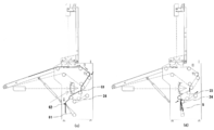
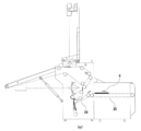
- the first invention is a folding machine including a folding mechanism for folding a sheet-like article conveyed by a plurality of conveyors, the longest first conveyor receiving the sheet-like article from a previous step, and the first A second conveyor that moves the sheet-like article downward in cooperation with the first conveyor, a third conveyor that continues between the second conveyor and the inspection plate, an imaging unit, and an illumination unit, And a back side inspection mechanism for inspecting a sheet-like article passing through the inspection plate from the back side, wherein the back side inspection mechanism is disposed below the first conveyor.
- a front side inspection mechanism for inspecting the sheet-like article from the front side is arranged above the first conveyor.
- a third invention is characterized in that, in the first or second invention, the first conveyor is provided with a sensor for measuring the length of the sheet-like article.
- 4th invention is a folding machine provided with the conveyor mechanism which consists of a some conveyor which conveys a sheet-like article, the folding mechanism which folds the sheet-like article conveyed by a conveyor mechanism, and a main body, The folding machine is characterized in that a back side inspection mechanism for inspecting a sheet-like article from the back side is disposed below the longest conveyor protruding from the main body.
- the conveyor mechanism includes an upper conveyor group and a lower conveyor group that are continuous with an inspection plate interposed therebetween, and the imaging unit and the illumination unit included in the back side inspection mechanism include the inspection unit. It is arranged to face the plate.
- the sixth invention is characterized in that in the fourth or fifth invention, the sheet-like article is further provided with a front side inspection mechanism for inspecting the sheet-like article from the front side.
- a seventh invention is characterized in that, in any one of the fourth to sixth inventions, the longest conveyor protruding from the main body is a conveyor arranged at an angle to receive a sheet-like article from the previous process. To do.
- An eighth invention is characterized in that, in any one of the fourth to seventh inventions, a sensor for measuring a length of a sheet-like article is provided on the longest conveyor protruding from the main body. .
- a ninth invention is characterized in that, in any one of the first to eighth inventions, the imaging section is constituted by one or two cameras. According to a tenth aspect, in any one of the first to ninth aspects, the inspection plate has a dark color area and a light color area.
- the present invention it is possible to provide a space-saving folding machine having an inspection function for sheet-like articles. Moreover, since the folding machine of the present invention has a simple structure, cost and maintenance are good.
- FIG. 3 is a plan view of a main part of a surface imaging unit according to Embodiment 1.
- FIG. 3 is a side view of the main part of the surface imaging unit according to the first embodiment.
- It is side surface sectional drawing (a), (b) for demonstrating the action
- FIG. It is side surface sectional drawing (c), (d) for demonstrating the action
- a folding machine of the best mode for carrying out the present invention includes a conveyor mechanism composed of a plurality of conveyors that convey sheet-like articles, a folding mechanism that folds sheet-like articles conveyed by the conveyor mechanism, and sheet-like articles.
- An inspection mechanism front side inspection mechanism
- An inspection mechanism back side inspection mechanism
- the conveyor mechanism is, for example, a first conveyor (21) that receives a sheet-like article from a previous process, and a first conveyor that sends the sheet-like article downward from the terminal end of the first conveyor in cooperation with the first conveyor.
- the first conveyor is provided with a sensor for measuring the length of the sheet-like article.
- a sensor is provided on the first conveyor which is the longest conveyor in the conveyor mechanism. Since the measurement of the length of the sheet-like article needs to be completed before the movable folding claw is operated, at least one of the conveyor mechanisms needs to be provided with a conveyor equivalent to or more than the sheet-like article. This is because the distance from the sensor to the movable folding claw needs to be at least the length of the sheet-like article minus the folding margin. For example, when the sheet-like article is folded in four, the folding margin is 1 ⁇ 4 of the total length, and thus the distance is at least 3/4 of the total length of the sheet-like article.
- the present invention since it is necessary to provide a conveyor having a length equal to or longer than that of the sheet-like article, the total length of the folding machine becomes longer as the sheet-like article becomes longer.
- the back side inspection mechanism in an empty space generated by the length of the first conveyor.
- the back side inspection mechanism is arranged between the longest conveyor and the floor surface under a long conveyor protruding from the main body.
- the present invention is characterized by effectively utilizing the structural problem that the conveyor becomes longer according to the length of the sheet-like article, and can be implemented with appropriate modifications within the scope of using this technical idea. Is possible.
- the present invention is suitable for a sheet-like article having a long side of 1 m or more, still more suitable for a sheet-like article having a long side of 2 m or more, and further suitable for a sheet-like article having a long side of 3 m or more.
- the merit from another viewpoint of arranging the back side inspection mechanism below the long conveyor is that the distance between the imaging unit and the sheet-like article can be secured.
- the distance between the imaging unit and the sheet-like article needs to be a certain value or more. This distance can be shortened to some extent by increasing the number of cameras constituting the imaging unit.
- increasing the number of cameras increases the cost of the apparatus, complicates adjustment and control, and reduces maintainability.
- the present invention provides a structure that can realize space saving even if the number of cameras is not three or four or more.
- the folding mechanism is composed of a sword for turning a sheet-shaped article into a gap between a pair of conveyors, folding the sheet-shaped article, a rotating plate-shaped claw, and the like.
- the folding mechanism is optimally configured according to the number of folding sheets.
- Patent Document 2 discloses a folding mechanism that folds a piece of cloth 32 times.
- the front side inspection mechanism and the back side inspection mechanism of the present invention have the same configuration and have the following features.
- Work detector that detects the moving speed of the article 4) Receives a signal from the work detector, sends an imaging start signal to the color camera, continuously receives the electrical signal of the line-shaped image captured by the color camera, Input unit for transfer to processing unit 5)
- Mask processing is performed on image data, and defect position information and defect type information (tear, black stain, non-black stain) detected in comparison with the defect level are transferred to the defect information storage unit.
- Processing unit 6 Storage unit for storing a two-dimensional RGB image obtained from line-shaped image data transferred from the processing unit 7) Defect information for storing defect position information and defect type information received from the processing unit Storage unit 8) Output unit that outputs a classification signal based on defect position information and defect type information stored in the defect information storage unit 9) Illumination controller unit that illuminates the area to be inspected in a line and increases or decreases the light quantity 10) Defect Display unit for displaying information stored in information storage unit and two-dimensional RGB image 11) Rejector for sorting sheet-like article in response to sorting signal
- the front side inspection mechanism and the back side inspection mechanism have the following functions.
- Image Data Capture Function A sheet-like article being conveyed by the conveying device can be stored in the storage means as a two-dimensional RGB image.
- the image data has a format in which a flowing inspection object is taken in two dimensions, and includes not only a defective portion but also noise such as a flaw and a ground. By adjusting the image data as it is instead of the input electric signal, it is not necessary to repeatedly flow the sheet-like article sample.
- Light intensity adjustment function This is a function that automatically adjusts the input light intensity to a certain level by increasing or decreasing the light intensity based on the image data captured from the image sensor.
- (III) Basic mask function The presence or absence of a defect is determined based on the captured image data. The region to be inspected is determined by performing mask processing on the image data. Since mask processing is applied to the image data, it is also possible to perform curved mask processing at a fixed distance along the edge of the detected sheet-like article. Also, it is designated from the center position of the sheet-like article. It is also possible to perform a width mask.
- Color mask function It has a color mask function for masking patterns such as logos and patterns attached to sheet-like articles.
- a color range based on a value obtained by digitizing the designated color with a predetermined algorithm is provided, and it is determined that an object belonging to the color range is a pattern, and mask processing is performed. This is performed by digitizing hues that have regularity in change even during pattern judgment and color loss, but may be combined with saturation and lightness.
- the specific procedure is as follows. i) Capture an RGB image of a sheet-like article. ii) Specify the part to be masked and capture the color. iii) Replace the captured color with a color space such as HSV, and digitize the hue.
- the hue is converted to a frequency (for example, 0 to 360 degrees), so that a color is specified with a threshold before and after the specified frequency (for example, in the case of red, the center is 0 degree). ).
- Color mask processing is performed based on the color range calculated based on the set value. With the above procedure, it is possible to accurately mask a pattern such as a logo / pattern.
- V Pattern-related information storage function The present invention is applied to a model business in which used sheet-like articles are regularly conveyed from a specific user. Therefore, by storing information related to the pattern of a sheet-like article that has been subjected to mask processing in the past, it is possible to minimize misunderstandings in color mask processing.
- a technique for storing a pattern signal in advance is disclosed, but as the number of patterns increases, the number of comparison objects increases, and a pattern for each direction is prepared in case the sheet-like article is placed in a different direction. Since it is necessary to prepare and matching with these data, there is a problem that the processing speed is lowered, which is not preferable. In order to obtain a constant processing speed without impairing the convenience of the operator, it is effective to store the relationship between the pattern and the area. Thus, if an abnormal value belonging to a specific color range and a specific area range is detected, it can be determined that the pattern is a pattern. Note that not only the area but also the aspect ratio, shape, position information, and the like may be used.
- (VI) Defect type information emphasis function Both tear information and dirt information are detected as noise on the image data of the workpiece, but it is difficult to accurately determine these types.
- the defect type information can be emphasized by passing the work on the inspection plate having a plurality of color regions and utilizing the characteristics of the three primary colors of light. That is, as shown in FIG. 4, three image lines of RGB are associated with the color region of the inspection plate, and each image data of RGB imaged is synthesized to obtain synthesized image data in which defect type information is emphasized. be able to. Even when the imaging unit is an area type color camera, the same effect can be obtained by appropriately setting the color components to be extracted at a predetermined position.
- the number of folds is increased so as not to take up space, and that non-black dirt is discharged with fewer folds so that it can be easily re-inspected by humans. .
- the number of different folds is discharged by associating the hue range with the defect type information. For example, since the tear is captured as a color close to cyan, if a color close to cyan is detected, it is determined that the tear is broken and the sheet is discharged with a predetermined number of folds. Similarly, non-black and black (or a color close to black) can be discharged with different fold numbers.
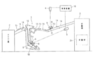
- FIG. 1 is a configuration diagram of a folding machine 3 having an ironing machine 2 in the previous process and an inspection mechanism of the present embodiment.
- the ironing machine 2 is a machine that automatically irons the spread fabric S.
- the cloth S ironed by the ironing machine 2 is transferred onto the belt conveyor 21 of the folding machine 3 in a stretched state (see FIG. 5A).
- the surface of the cloth S conveyed on the belt conveyor 21 is inspected by the surface imaging unit 4. As shown in FIG.
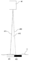
- the surface imaging unit 41 of this embodiment includes two line-type color cameras arranged on the same line, and lines the inspection target region of the cloth S in a direction orthogonal to the transport direction. Image.
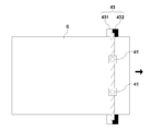
- the inspection target area of the cloth S is illuminated by the light source 42, and an inspection plate 43 is disposed below the inspection target area.
- the cloth S passes over the inspection plate 43. Since the cloth S is wide (for example, about 3 m), the surface imaging unit 41 captures 1 ⁇ 2 of the width of the cloth S with each camera.
- the surface imaging unit 4 may be constituted by a single color camera or may be constituted by an area type camera.
- the inspection plate 43 includes a white area 431 and a black area 432.
- the reason why the inspection plate 43 is composed of a light color area and a dark color area is to facilitate identification of defects.
- the torn image appears bright in the white area 431 and appears dark in the black area 432.
- the defect type information can be emphasized by associating three RGB lines and the color area of the inspection plate and synthesizing the captured RGB image data.
- the reflection in the white region 431 and the black region 432 changes in different manners between non-black stain and black stain. For example, yellow non-black stains appear darker in blue line image data than yellow non-black stains when they are combined with green line image data and red line image data.
- the tear is captured darkly only on the black region 432 (red line), it is captured as a color close to cyan in the composite image data.
- the black stain remains as it is after being synthesized. In this case, it can be said that a hue pattern in a certain range from a color close to cyan has a high probability of being broken.
- the length and movement speed of the cloth S are measured by the work detection sensor 45 and a conveyor speed detector (not shown).
- the imaging of the fabric S is performed by the imaging units 41 and 51 after the calculated time (see FIG. 5B).
- Various mask processes are performed on the image data from the imaging units 41 and 51, and defect determination work is performed. When it is determined that there is a defect by the defect determination work, a defect flag is recorded.
- the cloth S determined to be defective is sorted, and for example, the number of folds is changed and discharged to a different stacker.
- a belt conveyor 22 is disposed at the rear end of the belt conveyor 21.
- the cloth S sandwiched between the belt conveyor 21 and the belt conveyor 22 is conveyed in the direction of the belt conveyor 23.
- An inspection plate 53 having the same configuration as that of the inspection plate 43 is disposed between the belt conveyor 22 and the belt conveyor 23.
- the position of the inspection plate 53 is an inspection target region, and the inspection target region is illuminated by a light source 52 provided to face the inspection plate 53.
- the back surface imaging unit 51 images the inspection target part of the cloth S in a line shape from the gap between the light sources 51 arranged with a gap above and below.
- the back imaging unit 51 has the same configuration as the front imaging unit 41, and the light source 52 has the same configuration as the light source 42. Based on the image data imaged by the back surface imaging unit 51, the back surface inspection is performed by the same procedure as the front surface inspection.
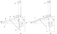
- the cloth S that has passed through the end of the belt conveyor 23 hangs down.
- the movable folding claw 61 is in a position that substantially contacts the conveyor 24.
- 1/4 of the cloth S hangs down and is in a state suitable for four-folding the movable folding claw 61 moves to the contact member 62 side, and the movable folding claw 61 and the contact member 62 sandwich the cloth S. (See FIG. 6C). Accordingly, the cloth S hangs down between the belt conveyor 24 and the movable folding claw 61 by the rotation of the belt conveyor 23.
- the inspection mechanism provided in the folding machine of the present embodiment is not limited to the above combination.
- a metal detector meter reading device
- the conveyance conveyor 25 may be provided with metal.
- a detector meter reading device
- the folding machine of the present embodiment having the above configuration, it is possible to reduce the installation space of a machine in a factory such as a laundry. Further, since the increase in the number of belt conveyors and the number of axes necessary for providing the double-sided inspection function can be minimized, the cost and maintenance are excellent.
Landscapes
- Engineering & Computer Science (AREA)
- Textile Engineering (AREA)
- Investigating Materials By The Use Of Optical Means Adapted For Particular Applications (AREA)
Applications Claiming Priority (2)
| Application Number | Priority Date | Filing Date | Title |
|---|---|---|---|
| JP2008-140306 | 2008-05-29 | ||
| JP2008140306A JP5248919B2 (ja) | 2008-05-29 | 2008-05-29 | 検査機能を有する折畳機 |
Publications (1)
| Publication Number | Publication Date |
|---|---|
| WO2009144905A1 true WO2009144905A1 (ja) | 2009-12-03 |
Family
ID=41376795
Family Applications (1)
| Application Number | Title | Priority Date | Filing Date |
|---|---|---|---|
| PCT/JP2009/002277 Ceased WO2009144905A1 (ja) | 2008-05-29 | 2009-05-22 | 検査機能を有する折畳機 |
Country Status (2)
| Country | Link |
|---|---|
| JP (1) | JP5248919B2 (enExample) |
| WO (1) | WO2009144905A1 (enExample) |
Cited By (2)
| Publication number | Priority date | Publication date | Assignee | Title |
|---|---|---|---|---|
| EP3075896A1 (de) * | 2015-04-01 | 2016-10-05 | Herbert Kannegiesser GmbH | Verfahren und vorrichtung zum nachbehandeln von wäschestücken |
| EP3093385A1 (de) * | 2015-05-13 | 2016-11-16 | Herbert Kannegiesser GmbH | Verfahren und vorrichtung zum nachbehandeln von wäschestücken |
Families Citing this family (7)
| Publication number | Priority date | Publication date | Assignee | Title |
|---|---|---|---|---|
| JP4792521B2 (ja) * | 2009-12-15 | 2011-10-12 | 株式会社アイ.エス.テイ | 布製品識別装置および布製品把持システム |
| JP5881278B2 (ja) * | 2010-05-20 | 2016-03-09 | 株式会社プレックス | 布片検査装置および検査方法 |
| JP5952136B2 (ja) * | 2012-08-29 | 2016-07-13 | 倉敷紡績株式会社 | 布片の縁部の自動検出方法とその装置、および、該装置を有する布片展開送り装置 |
| JP6048872B2 (ja) * | 2012-09-04 | 2016-12-21 | 株式会社プレックス | 布片検査方法および布片検査装置 |
| JP6108535B2 (ja) * | 2013-03-27 | 2017-04-05 | 株式会社プレックス | 布類検査装置 |
| JP6133161B2 (ja) * | 2013-07-27 | 2017-05-24 | 株式会社プレックス | 布類捌き装置 |
| JP7185500B2 (ja) * | 2018-11-14 | 2022-12-07 | 東都フォルダー工業株式会社 | シート材の画像処理装置 |
Citations (3)
| Publication number | Priority date | Publication date | Assignee | Title |
|---|---|---|---|---|
| JPH0633368A (ja) * | 1992-07-14 | 1994-02-08 | Gunze Ltd | 生地の検反方法およびその装置 |
| JP2000329701A (ja) * | 1999-02-12 | 2000-11-30 | Pouya Firouzu | シート状物品面の欠陥を検査する方法及び検査板 |
| JP3813121B2 (ja) * | 2002-11-29 | 2006-08-23 | 株式会社プレックス | 布片検査装置 |
-
2008
- 2008-05-29 JP JP2008140306A patent/JP5248919B2/ja active Active
-
2009
- 2009-05-22 WO PCT/JP2009/002277 patent/WO2009144905A1/ja not_active Ceased
Patent Citations (3)
| Publication number | Priority date | Publication date | Assignee | Title |
|---|---|---|---|---|
| JPH0633368A (ja) * | 1992-07-14 | 1994-02-08 | Gunze Ltd | 生地の検反方法およびその装置 |
| JP2000329701A (ja) * | 1999-02-12 | 2000-11-30 | Pouya Firouzu | シート状物品面の欠陥を検査する方法及び検査板 |
| JP3813121B2 (ja) * | 2002-11-29 | 2006-08-23 | 株式会社プレックス | 布片検査装置 |
Cited By (2)
| Publication number | Priority date | Publication date | Assignee | Title |
|---|---|---|---|---|
| EP3075896A1 (de) * | 2015-04-01 | 2016-10-05 | Herbert Kannegiesser GmbH | Verfahren und vorrichtung zum nachbehandeln von wäschestücken |
| EP3093385A1 (de) * | 2015-05-13 | 2016-11-16 | Herbert Kannegiesser GmbH | Verfahren und vorrichtung zum nachbehandeln von wäschestücken |
Also Published As
| Publication number | Publication date |
|---|---|
| JP5248919B2 (ja) | 2013-07-31 |
| JP2009285109A (ja) | 2009-12-10 |
Similar Documents
| Publication | Publication Date | Title |
|---|---|---|
| JP4440281B2 (ja) | シート状物品の検査方法および装置 | |
| JP5248919B2 (ja) | 検査機能を有する折畳機 | |
| EP2573550B1 (en) | Cloth inspection device and inspection method | |
| JP4973332B2 (ja) | 海苔の外観検査装置 | |
| JP2004257929A (ja) | 転写箔欠点検査装置 | |
| JP6120405B2 (ja) | 布類検査装置 | |
| JP2011079564A (ja) | 包装不良検査方法及び装置 | |
| WO2017207115A1 (en) | Surface inspection system and inspection method | |
| WO1998001746A1 (en) | Visual inspection apparatus | |
| JP3813121B2 (ja) | 布片検査装置 | |
| JP5818948B2 (ja) | 布片検査装置 | |
| JP2018124127A (ja) | シート検査装置 | |
| JP2010099235A (ja) | 検査装置付き折畳機 | |
| JPH08276100A (ja) | 布片欠陥検出装置 | |
| JP4174305B2 (ja) | 欠陥布類検出装置 | |
| JPH0710720Y2 (ja) | 布片欠陥検査装置 | |
| JP2008128822A (ja) | 透光性を有するシート材の外観検査装置および方法 | |
| JP2004093486A (ja) | 欠陥布片検出装置における欠陥レベル情報設定方法 | |
| JPH095258A (ja) | シート状面の欠陥を検査する方法および装置 | |
| CN223669701U (zh) | 一种基于机器视觉的纸袋缺陷检测装置 | |
| JP2017177495A (ja) | 印刷物検査方法および装置 | |
| JP6216591B2 (ja) | シート材の外観検査装置 | |
| JP3634300B2 (ja) | 布類の重ね折り装置 | |
| JP2020079775A (ja) | シート材の画像処理装置 | |
| JPH08299700A (ja) | 布片欠陥検出装置 |
Legal Events
| Date | Code | Title | Description |
|---|---|---|---|
| 121 | Ep: the epo has been informed by wipo that ep was designated in this application |
Ref document number: 09754414 Country of ref document: EP Kind code of ref document: A1 |
|
| DPE1 | Request for preliminary examination filed after expiration of 19th month from priority date (pct application filed from 20040101) | ||
| NENP | Non-entry into the national phase |
Ref country code: DE |
|
| 122 | Ep: pct application non-entry in european phase |
Ref document number: 09754414 Country of ref document: EP Kind code of ref document: A1 |