WO2009131211A1 - 車輪用転がり軸受装置の熱処理方法と内軸の冷却装置 - Google Patents
車輪用転がり軸受装置の熱処理方法と内軸の冷却装置 Download PDFInfo
- Publication number
- WO2009131211A1 WO2009131211A1 PCT/JP2009/058162 JP2009058162W WO2009131211A1 WO 2009131211 A1 WO2009131211 A1 WO 2009131211A1 JP 2009058162 W JP2009058162 W JP 2009058162W WO 2009131211 A1 WO2009131211 A1 WO 2009131211A1
- Authority
- WO
- WIPO (PCT)
- Prior art keywords
- inner shaft
- outer ring
- raceway surface
- flange
- heat treatment
- Prior art date
- Legal status (The legal status is an assumption and is not a legal conclusion. Google has not performed a legal analysis and makes no representation as to the accuracy of the status listed.)
- Ceased
Links
Images


Classifications
-
- F—MECHANICAL ENGINEERING; LIGHTING; HEATING; WEAPONS; BLASTING
- F16—ENGINEERING ELEMENTS AND UNITS; GENERAL MEASURES FOR PRODUCING AND MAINTAINING EFFECTIVE FUNCTIONING OF MACHINES OR INSTALLATIONS; THERMAL INSULATION IN GENERAL
- F16C—SHAFTS; FLEXIBLE SHAFTS; ELEMENTS OR CRANKSHAFT MECHANISMS; ROTARY BODIES OTHER THAN GEARING ELEMENTS; BEARINGS
- F16C33/00—Parts of bearings; Special methods for making bearings or parts thereof
- F16C33/30—Parts of ball or roller bearings
- F16C33/58—Raceways; Race rings
- F16C33/64—Special methods of manufacture
-
- C—CHEMISTRY; METALLURGY
- C21—METALLURGY OF IRON
- C21D—MODIFYING THE PHYSICAL STRUCTURE OF FERROUS METALS; GENERAL DEVICES FOR HEAT TREATMENT OF FERROUS OR NON-FERROUS METALS OR ALLOYS; MAKING METAL MALLEABLE, e.g. BY DECARBURISATION OR TEMPERING
- C21D1/00—General methods or devices for heat treatment, e.g. annealing, hardening, quenching or tempering
- C21D1/62—Quenching devices
-
- C—CHEMISTRY; METALLURGY
- C21—METALLURGY OF IRON
- C21D—MODIFYING THE PHYSICAL STRUCTURE OF FERROUS METALS; GENERAL DEVICES FOR HEAT TREATMENT OF FERROUS OR NON-FERROUS METALS OR ALLOYS; MAKING METAL MALLEABLE, e.g. BY DECARBURISATION OR TEMPERING
- C21D1/00—General methods or devices for heat treatment, e.g. annealing, hardening, quenching or tempering
- C21D1/62—Quenching devices
- C21D1/63—Quenching devices for bath quenching
-
- C—CHEMISTRY; METALLURGY
- C21—METALLURGY OF IRON
- C21D—MODIFYING THE PHYSICAL STRUCTURE OF FERROUS METALS; GENERAL DEVICES FOR HEAT TREATMENT OF FERROUS OR NON-FERROUS METALS OR ALLOYS; MAKING METAL MALLEABLE, e.g. BY DECARBURISATION OR TEMPERING
- C21D9/00—Heat treatment, e.g. annealing, hardening, quenching or tempering, adapted for particular articles; Furnaces therefor
- C21D9/40—Heat treatment, e.g. annealing, hardening, quenching or tempering, adapted for particular articles; Furnaces therefor for rings; for bearing races
-
- C—CHEMISTRY; METALLURGY
- C21—METALLURGY OF IRON
- C21D—MODIFYING THE PHYSICAL STRUCTURE OF FERROUS METALS; GENERAL DEVICES FOR HEAT TREATMENT OF FERROUS OR NON-FERROUS METALS OR ALLOYS; MAKING METAL MALLEABLE, e.g. BY DECARBURISATION OR TEMPERING
- C21D2211/00—Microstructure comprising significant phases
- C21D2211/008—Martensite
-
- F—MECHANICAL ENGINEERING; LIGHTING; HEATING; WEAPONS; BLASTING
- F16—ENGINEERING ELEMENTS AND UNITS; GENERAL MEASURES FOR PRODUCING AND MAINTAINING EFFECTIVE FUNCTIONING OF MACHINES OR INSTALLATIONS; THERMAL INSULATION IN GENERAL
- F16C—SHAFTS; FLEXIBLE SHAFTS; ELEMENTS OR CRANKSHAFT MECHANISMS; ROTARY BODIES OTHER THAN GEARING ELEMENTS; BEARINGS
- F16C2326/00—Articles relating to transporting
- F16C2326/01—Parts of vehicles in general
- F16C2326/02—Wheel hubs or castors
Definitions
- the present invention relates to a heat treatment method for a raceway surface of a rolling bearing device for a wheel for rotatably supporting a wheel on a suspension device such as an automobile, and an inner shaft cooling device used in the heat treatment method.
- FIG. 1 is a cross-sectional view showing an example of a rolling bearing device 1 for a wheel that is becoming popular in recent years.
- a rolling bearing device 1 for a wheel according to this example includes a cylindrical outer ring 2, an inner shaft 3 that is inserted through the cylinder and arranged coaxially with the outer ring 2, and the outer ring 2 and the inner shaft. And a plurality of rolling elements 4 interposed between them.
- double-row (two rows in the figure) raceway surfaces 5 and 6 that support the rolling elements 4 so as to roll are formed on the inner periphery of the outer ring 2, double-row (two rows in the figure) raceway surfaces 5 and 6 that support the rolling elements 4 so as to roll are formed.
- a flange 8 having a protruding portion 7 is formed integrally with the cylinder.
- a raceway surface 13 is formed on the outer peripheral surface of the inner shaft 3 so as to face the raceway surface 5 and support the rolling element 4 so as to roll between the raceway surface 5.
- a race ring 14 is fitted on the outer circumference of the inner shaft 3 at a position facing the raceway surface 6. The raceway is opposed to the raceway surface 6 on the outer circumference of the raceway ring 14.
- a raceway surface 15 is formed to support 4 in a rollable manner.
- the inner shaft 3 is integrally formed with a flange 19 projecting outward in the radial direction of the inner shaft 3 for attaching a wheel, a brake disk or the like.
- a cylindrical cannula portion 21 is provided on the side surface of the flange 19 opposite to the side on which the raceway surface 13 is formed so as to project from the side surface in the axial direction of the inner shaft 3 to fit the brake disc.
- the outer ring 2 is formed by, for example, hot forging a steel material such as bearing steel or carbon steel for machine structure to form a precursor (work), and heat-treat the raceway surfaces 5 and 6 of the work. Then, after a hardened layer having a predetermined thickness is formed in a region including the raceway surfaces 5 and 6, the surface is polished as necessary.
- so-called induction hardening in which the raceway surfaces 5 and 6 are locally heated and then cooled by induction heating with a high frequency coil, for example, in the atmosphere is widely employed.
- the workpiece has a thin cylindrical shape with a thickness of about 10 mm or less, and the thickness of the cylinder in the axial direction is not constant, such as having raceway surfaces 5 and 6 on the inner periphery and flange 8 on the outer periphery.
- tube is not constant.
- the raceway surfaces 5 and 6 are heat-treated, there is a risk that large distortion will occur in the entire workpiece, for example, the roundness of the cylinder may be reduced.
- the heat of the heat treatment is conducted non-uniformly to the non-heated region of the work based on the difference in the thickness, etc., so that non-uniform expansion occurs in the work and internal stress is generated.
- heated workpieces are cooled by spraying water from a large number of water outlets in the form of showers.
- the arrival time and arrival time of water are determined based on the shape of the workpiece. Due to a difference in the amount and the like, the whole workpiece cannot be cooled uniformly at the same time. Therefore, since internal stress is generated and non-uniform cooling is performed, the workpiece may be deformed abnormally, which may cause a large distortion on the whole.
- the inner shaft 3 is formed by forming a workpiece that is the basis of the steel material by hot forging or the like, heat-treating the raceway surface 13 of the workpiece, and hardening the region including the raceway surface 13 to have a predetermined thickness. After the layer is formed, the surface is polished if necessary. As the heat treatment, induction hardening is widely adopted. Since the brake disc and the wheel are attached to the left side surface of the flange 19 in the state in which the wax part 21 is fitted to the brake disc, the side surface is as flat as possible on the inner shaft 3. At the same time, it is required that the enamel portion 21 is not distorted. However, if the raceway surface 13 is heat-treated, the flange 19 may be distorted, and the flatness of the side surface may be deteriorated, or the enamel portion 21 may be distorted.
- the heat of the heat treatment is gradually transmitted from the base portion of the flange 19 close to the raceway surface 13 toward the peripheral portion, so that nonuniform expansion occurs between the base portion side and the peripheral portion side, thereby generating internal stress.
- water is sprayed in a shower shape and cooled, it deforms abnormally to cause distortion, and the flatness of the side surface may be lowered.
- the flange 19 is distorted, the enamel portion 21 formed integrally with the flange 19 is also distorted.
- the present invention has been made under such a background.
- An outer ring and an inner shaft having the required dimensional accuracy can be obtained without further turning the workpiece after heat treatment or causing unevenness of quenching. It aims at providing the heat processing method of the rolling bearing apparatus for wheels which can be formed.
- Another object of the present invention is to provide an inner shaft cooling device used in the heat treatment method.
- the present invention has an outer ring (2) having a cylindrical shape and having raceway surfaces (5) and (6) formed on the inner periphery thereof, A raceway surface of a rolling bearing device (1) for a wheel comprising an outer peripheral surface having a raceway surface (13) and a flange (19) for attaching a wheel, and an inner shaft (3) arranged coaxially with the outer ring.
- a heat treatment method for a rolling bearing device is provided (claim 1).
- alphanumeric characters in parentheses represent corresponding components in the embodiments described later.
- the present invention in the case of the outer ring, heat treatment of the outer ring or the inner shaft is continued in the vicinity of the raceway surface being heated with water for a predetermined time from heating to after heating. It is possible to suppress the occurrence of internal stress in the outer ring due to non-uniform conduction to the non-heated region. Moreover, the entire outer ring can be uniformly and uniformly cooled only by stopping the heating. Therefore, it is possible to prevent the outer ring from deforming due to heat treatment and causing a large distortion on the whole, and even if the process of further turning the outer ring after the heat treatment to correct the distortion is omitted, the dimensional accuracy required for the outer ring is improved. It becomes possible to put out.
- the flange in the case of the inner shaft, the flange can be uniformly cooled, and the occurrence of the distortion of the flange due to the internal stress and the distortion of the enamel portion accompanying it can be suppressed. Therefore, even if the step of correcting the distortion by further turning the side surface of the flange and the heat-treated flange is omitted, the flatness required for the side surface can be obtained and the dimensional accuracy of the heat-treated portion can be obtained. It becomes possible. Therefore, the productivity of the outer ring, the inner shaft, and thus the rolling bearing device for the wheel can be improved as much as the turning process can be omitted.
- a high-frequency coil (28) for induction heating is inserted into the cylindrical outer ring and is opposed to the inner raceway surface.
- the outer ring is rotated relative to the high-frequency coil in the circumferential direction around the axis (A) of the cylinder, and the high-frequency coil is energized while spraying water (27) on the entire outer peripheral surface of the outer ring and cooling it. It is preferable to heat the raceway surface and cool for a predetermined time after the heating is finished.
- the high frequency coil (41) for induction heating is provided with the inner shaft raceway surface.
- the inner shaft is rotated relative to the high-frequency coil in the circumferential direction around the axis, and the high-frequency coil is energized while being cooled by contacting the flange of the inner shaft with water (27). It is preferable to heat the raceway surface and to cool for a certain time after the heating is finished.
- the present invention holds an inner shaft of a rolling bearing device for a wheel in which an outer peripheral surface having a raceway surface and a flange for attaching a wheel are integrally formed, with the outer peripheral surface having the raceway surface being up and the flange being down.
- a holding portion (32) rotatable in a circumferential direction around the axis of the held inner shaft, wherein the holding portion supplies water to a lower side surface of the held flange and makes the flange contact with the side surface.
- the present invention provides an inner shaft cooling device (31) characterized by having a flow path of water that flows out after cooling.
- the holding portion holds the inner shaft, the holding portion is rotated about the held inner shaft, and water is circulated through the flow path to cool the flange.
- the raceway surface By heating the raceway surface by, for example, induction heating and then cooling, the raceway surface can be heat-treated while suppressing deformation of the flange and the wax part.
- FIG. 1 is a cross-sectional view showing an example of a wheel rolling bearing device 1 as described above.
- a wheel rolling bearing device 1 of this example includes a cylindrical outer ring 2, an inner shaft 3 that is inserted through the cylinder and is coaxially arranged with respect to the outer ring 2 and the axis A, and A plurality of rolling elements 4 interposed between the outer ring 2 and the inner shaft 3 are provided.
- a double row (two rows in the figure) raceway surfaces 5 and 6 are formed on the inner periphery of the outer ring 2 so as to support the rolling elements 4 in a rollable manner. Further, on the outer periphery of the cylinder, there are a plurality of parts for mounting to the suspension device, which project from a plurality of circumferential positions (only one is shown in the figure) toward the outer side in the radial direction of the cylinder.
- a flange 8 having a protruding portion 7 is formed integrally with the cylinder. The flange 8 is formed with a screw hole 9 into which a bolt (not shown) for attachment to the suspension device is screwed so as to penetrate in the axial direction of the cylinder.
- the inner shaft 3 is a large-diameter portion 10 having a large outer diameter and integrally formed so as to be coaxial in order from one end side (left side in the drawing) to the other end side (right side) in the direction of the axis A.
- a medium diameter portion 11 having an outer diameter smaller than 10 and a small diameter portion 12 having an outer diameter smaller than that of the medium diameter portion 11, and a step portion between the large diameter portion 10 and the medium diameter portion 11 is provided on the raceway surface 5.
- Opposing track surfaces 13 are formed.
- a raceway ring 14 is fitted to the small diameter portion 12, and a raceway surface 15 facing the raceway surface 6 is formed on the outer periphery of the raceway ring 14.
- the race ring 14 has a cylindrical shape whose inner diameter matches the outer diameter of the small-diameter portion 12 and is integrally formed so as to be coaxial in order from one end side to the other end side in the axis A direction. And a large-diameter portion 17 having an outer diameter larger than that of the small-diameter portion 16. Has been.
- the end 18 of the small-diameter portion 12 of the inner shaft 3 is formed in a cylindrical shape having the same diameter as the small-diameter portion 12 before assembly of the wheel rolling bearing device 1 as indicated by a broken line in the drawing.
- the rolling bearing device 1 In order to assemble the rolling bearing device 1 for a wheel, a small diameter is maintained while holding a predetermined number of rolling elements 4 between the raceway surface 5 and the raceway surface 13 and between the raceway surface 6 and the raceway surface 15.
- the track ring 14 is fitted to the portion 12 and one end thereof is brought into contact with the step between the medium diameter portion 11 and the small diameter portion 12.
- the end 18 is caulked to fix the bearing ring 14 to the inner shaft 3 and assemble the rolling bearing device 1 for the wheel.
- the rolling element 4, the raceway surfaces 5, 6 and The raceway surfaces 13 and 15 constitute a double-row thrust angular ball bearing, and the inner shaft 3 is supported by the outer ring 2 so as to be rotatable about the axis A.
- a flange 19 is integrally formed on the outer periphery of the inner shaft 3 on one end side of the large-diameter portion 10 so as to protrude radially outward from the outer periphery to fix a wheel, a brake disk, or the like. Yes.
- Bolts 20 for attaching wheels and brake disks (not shown) are provided at a plurality of locations (only one location is shown in the figure) in the circumferential direction of the flange 19.
- a cylindrical canopy portion 21 is integrally formed so as to project from the side surface to one end side and to fit the brake disc.
- the outer ring 2 is formed in the shape shown in FIG. 1 by hot forging, for example, bearing steel, carbon steel for machine structure, and the like, and then heat-treats the raceway surfaces 5 and 6. Then, after a hardened layer having a predetermined thickness is formed in a region including the raceway surfaces 5 and 6, the surface is polished as necessary.
- the inner shaft 3 is formed in the shape shown in FIG. 1 by hot forging the steel material as in the prior art, and the raceway surface 13 is then heat-treated to form a predetermined thickness in a region including the raceway surface 13. After forming a cured layer having a surface, the surface is polished if necessary.
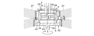
- FIG. 2 is a cross-sectional view showing an example of the heat treatment process for the outer ring 2 in the heat treatment method for the wheel rolling bearing device of the present invention. Referring to FIG. 2, in this example, a turntable 22 that rotates while holding the outer ring 2 is prepared.
- the turntable 22 is formed integrally with the base plate 23 that is in contact with the end face on the other end side (the lower side in the figure) of the outer ring 2, and the outer periphery of the other end side of the outer ring 2. And a cylindrical projection 25 that closes the opening 24 on the other end side together with the base plate 23, and a rotation shaft 26 attached to the lower surface of the base plate 23.
- the protruding portion 25 and the rotating shaft 26 are provided coaxially so that the axis A of the cylinder of the outer ring 2 coincides with the central axis of the rotating shaft 26 in a state where the protruding portion 25 is fitted to the other end side of the outer ring 2. ing.
- a high-frequency coil 28 for induction heating is inserted into the cylinder of the outer ring 2 held by the turntable 22 with the projecting portion 25 fitted and the end surface abutted against the upper surface of the base plate 23.
- the winding diameter is set to a diameter that can be inserted into the cylinder of the outer ring 2 and as close as possible to the raceway surfaces 5 and 6, and the number of turns in the axis A direction is set to the raceway surface 5.
- 6 is used in accordance with the number of rows (2 rows), and the winding interval is the same as the formation interval of the raceway surfaces 5 and 6.
- the high-frequency coil 28 is connected to a high-frequency power source (not shown).
- the high-frequency coil 28 is covered with an opening 29 on one end side (upper side in the drawing) of the outer ring 2 in a state where the double winding portion faces the raceway surfaces 5 and 6, and the lid 30 closes the opening 29. It has. As a result, the openings 24 and 29 on the other end side and one end side of the outer ring 2 are closed by the turntable 22 and the lid 30, and water 27 is prevented from entering the space in the cylinder of the outer ring 2. Is done.
- an additive such as a water-soluble polymer may be added to the water 27 as necessary.
- the temperature of the induction heating is set to a temperature at which the steel material forming the region of the outer ring 2 exhibits an austenite phase. The site is transformed and quenched.
- the entire outer peripheral surface of the outer ring 2 is continuously cooled by spraying water 27 during the heat treatment, so that the heat is non-uniformly conducted to the non-heated region to the outer ring 2. Generation of internal stress can be suppressed. Further, by continuing to spray water 27 for a certain period of time after stopping the heating, the entire outer ring 2 can be cooled uniformly at the same time.
- the outer ring 2 is required. It is possible to obtain dimensional accuracy. Accordingly, the productivity of the outer ring 2 and, consequently, the rolling bearing device 1 for wheels can be improved by the amount that the process can be omitted. In addition, since it is not necessary to form the work that is the basis of the outer ring 2 slightly larger in consideration of the amount of turning after heat treatment, the amount of steel required for manufacturing the outer ring 2, the energy required for transportation, and the space required for storage Etc. can all be reduced.
- the outer ring 2 is dried as necessary, and then assembled in combination with the rolling element 4, the inner shaft 3, and the bearing ring 14 in the procedure described above, the wheel rolling bearing device 1 shown in FIG. Manufactured.
- FIG. 3 is a cross-sectional view showing an example of a step of heat-treating the inner shaft 3 using an example of the cooling device of the present invention in the heat treatment method for the rolling bearing device for wheels of the present invention.
- the cooling device 31 used in this example holds the inner shaft 3 with the outer peripheral surface having the raceway surface 13 up and the flange 19 down, and holds the shaft of the held inner shaft 3.
- a holding portion 32 that can rotate in the circumferential direction about A is included.
- the holding portion 32 protrudes upward from the upper surface of the bottom plate 33 and the bottom plate 33, abuts against the lower side surface of the flange 19 in the drawing, and opens a gap between the flange 19 and the bottom plate 33.
- a cylindrical receiving portion 34 is provided.
- the receiving part 34 has an inner diameter of the cylinder larger than an outer diameter of the wax part 21, and a protruding height from the upper surface of the bottom plate 33 is set higher than the height of the wax part 21 in the axis A direction. . Therefore, in a state where the flange 19 is supported by the receiving portion 34, the wax portion 21 is inserted into the cylinder of the receiving portion 34 and is supported in a state where a gap is provided between the bottom plate 33.
- the holding portion 32 is formed integrally with the peripheral edge of the bottom plate 33 and is brought into contact with the outer periphery of the flange 19 supported by the receiving portion 34 so as to partition the gap between the flange 19 and the bottom plate 33 from the outside.
- a rotating shaft 36 attached to the lower surface of the bottom plate 33.
- the protruding portion 35 and the rotating shaft 36 are provided coaxially so that the axis A of the inner shaft 3 coincides with the central axis of the rotating shaft 36 in a state where the protruding portion 35 is in contact with the outer periphery of the flange 19. .
- a through hole 37 that connects the inside and outside of the cylinder is formed at the base of the receiving portion 34, and a through hole 38 that connects between a water supply means (not shown) and the upper surface of the bottom plate 33 is formed in the rotating shaft 36. ing.
- the flange 19 passes through the through hole 38, the gap between the receiving portion 34, the gap between the wax portion 21 and the bottom plate 33, the through hole 37, and the outside of the receiving portion 34, as indicated by the dashed arrows in the drawing.
- the flow path of the water 27 reaching the spline hole 39 to which the bolt 20 is attached is configured.
- a receiving tool 40 for preventing shaft runout rotating around the axis A in a state fitted to the end 18 is attached.
- a high-frequency coil 41 for induction heating is extrapolated to the inner shaft 3.
- the winding diameter is set to a diameter that can be extrapolated to the inner shaft 3 and as close as possible to the raceway surface 13, and the number of turns in the axis A direction is the number of rows of the raceway surface 13.
- a single winding is used in accordance with (one row).
- the high frequency coil 41 is connected to a high frequency power source (not shown).
- the temperature of the induction heating is set to a temperature at which the steel material forming the region of the inner shaft 3 exhibits an austenite phase, and when the temperature reaches the temperature and cools after a predetermined time has passed, the steel material forming the region undergoes martensitic transformation. To be quenched.
- the flange 19 and the wax part 21 of the inner shaft 3 are continuously cooled by the water 27 continuously supplied through the flow path. Generation
- the productivity of the rolling bearing device 1 for the inner shaft 3 and thus the wheel rolling bearing device 1 can be improved by the amount that the process can be omitted.
- the amount of steel necessary for manufacturing the inner shaft 3 since it is not necessary to form the work on which the inner shaft 3 becomes a little larger in consideration of the amount of turning after heat treatment, the amount of steel necessary for manufacturing the inner shaft 3, energy required for transportation, storage It is possible to reduce the space required for the process.
- the occurrence of quenching unevenness can be suppressed, and the thickness and spread of the cured layer formed by the heat treatment can be made uniform.
- the inner shaft 3 is dried as necessary, and then assembled in combination with the rolling elements 4, the outer ring 2, and the bearing ring 14 in the procedure described above, the wheel rolling bearing device 1 shown in FIG. Manufactured.
- the outer ring 2 subjected to the heat treatment in FIG. 2 and the inner shaft 3 subjected to the tempering process in FIG. 3 may be combined. In that case, the productivity of the wheel rolling bearing device 1 can be further improved.
- the present invention is not limited to the above embodiments, and various modifications can be made within the scope of the claims.
- the high frequency coil 28 is fixed and the outer ring 2 is rotated to perform heat treatment, but conversely, the outer ring 2 may be fixed and the high frequency coil 28 may be rotated to perform heat treatment. And the high frequency coil 28 may be rotated together for heat treatment.
- the rotation direction and the rotation speed of the outer ring 2 and the high-frequency coil 28 may be different so that the outer ring 2 and the high-frequency coil 28 rotate relative to each other.
- the high frequency coil 41 is fixed and the inner shaft 3 is rotated to perform heat treatment, but conversely, the inner shaft 3 may be fixed and the high frequency coil 41 may be rotated to perform heat treatment.
- the inner shaft 3 and the high-frequency coil 41 may be rotated together for heat treatment.
- the rolling bearing device for a wheel manufactured according to the present invention is not limited to that shown in FIG. 1, and both conventional two-row raceway surfaces are formed on a raceway separate from the inner shaft 3.
- the two orbital track surfaces currently being developed may be formed directly on the outer peripheral surface of the inner shaft 3.
- the raceway surface can be heat-treated in a state where an outer ring whose raceway surface is arbitrarily arranged in accordance with the arrangement of the raceway surface is immersed in water.
Landscapes
- Engineering & Computer Science (AREA)
- Chemical & Material Sciences (AREA)
- Mechanical Engineering (AREA)
- Materials Engineering (AREA)
- Crystallography & Structural Chemistry (AREA)
- Thermal Sciences (AREA)
- Physics & Mathematics (AREA)
- Metallurgy (AREA)
- Organic Chemistry (AREA)
- General Engineering & Computer Science (AREA)
- Manufacturing & Machinery (AREA)
- Rolling Contact Bearings (AREA)
- Heat Treatment Of Articles (AREA)
Priority Applications (2)
| Application Number | Priority Date | Filing Date | Title |
|---|---|---|---|
| US12/736,614 US20110036830A1 (en) | 2008-04-25 | 2009-04-24 | Heat treating method of rolling bearing device for wheel and cooling unit for inner shaft |
| CN2009801146370A CN102016084B (zh) | 2008-04-25 | 2009-04-24 | 车轮用滚动轴承装置的热处理方法和用于内轴的冷却单元 |
Applications Claiming Priority (2)
| Application Number | Priority Date | Filing Date | Title |
|---|---|---|---|
| JP2008116228A JP5365831B2 (ja) | 2008-04-25 | 2008-04-25 | 車輪用転がり軸受装置の熱処理方法と内軸の冷却装置 |
| JP2008-116228 | 2008-04-25 |
Publications (1)
| Publication Number | Publication Date |
|---|---|
| WO2009131211A1 true WO2009131211A1 (ja) | 2009-10-29 |
Family
ID=41216937
Family Applications (1)
| Application Number | Title | Priority Date | Filing Date |
|---|---|---|---|
| PCT/JP2009/058162 Ceased WO2009131211A1 (ja) | 2008-04-25 | 2009-04-24 | 車輪用転がり軸受装置の熱処理方法と内軸の冷却装置 |
Country Status (4)
| Country | Link |
|---|---|
| US (1) | US20110036830A1 (https=) |
| JP (1) | JP5365831B2 (https=) |
| CN (1) | CN102016084B (https=) |
| WO (1) | WO2009131211A1 (https=) |
Families Citing this family (3)
| Publication number | Priority date | Publication date | Assignee | Title |
|---|---|---|---|---|
| CN104313274B (zh) * | 2014-11-12 | 2016-04-20 | 中南大学 | 一种铝合金环形件喷淋淬火设备及其使用方法 |
| CN108546802B (zh) * | 2018-05-23 | 2019-11-22 | 燕山大学 | 一种内腔体零件水下电磁热处理装置及方法 |
| CN121344324B (zh) * | 2025-12-18 | 2026-03-17 | 人本股份有限公司 | 轴承外圈局部感应加热和硬度软化设备及其工艺 |
Citations (4)
| Publication number | Priority date | Publication date | Assignee | Title |
|---|---|---|---|---|
| JPS60159114A (ja) * | 1984-01-27 | 1985-08-20 | High Frequency Heattreat Co Ltd | 鍔付き筒体の低歪焼入れ装置 |
| JP2006291250A (ja) * | 2005-04-06 | 2006-10-26 | Nsk Ltd | 車輪支持用転がり軸受ユニット |
| JP2008045718A (ja) * | 2006-08-21 | 2008-02-28 | Nsk Ltd | 軸受ユニット |
| JP2008127666A (ja) * | 2006-11-24 | 2008-06-05 | Ntn Corp | 車輪用軸受装置における外方部材の熱処理方法 |
Family Cites Families (6)
| Publication number | Priority date | Publication date | Assignee | Title |
|---|---|---|---|---|
| US2167798A (en) * | 1935-08-19 | 1939-08-01 | Ohio Crankshaft Co | Apparatus for heat treating gears and the like |
| US4855551A (en) * | 1986-06-25 | 1989-08-08 | Tocco, Inc. | Method and apparatus for hardening gears |
| CN100347459C (zh) * | 2002-07-15 | 2007-11-07 | 日本精工株式会社 | 车轮支撑用滚动轴承单元 |
| JP2005188599A (ja) * | 2003-12-25 | 2005-07-14 | Ntn Corp | 車輪用軸受装置 |
| JP2006077268A (ja) * | 2004-09-07 | 2006-03-23 | Nsk Ltd | ハブユニットの軌道輪の製造方法及びハブユニットの軌道輪 |
| EP2050583B1 (en) * | 2006-08-07 | 2013-12-04 | NSK Ltd. | Raceway ring member for bearing unit, bearing unit, and method and device for producing raceway ring member for bearing unit |
-
2008
- 2008-04-25 JP JP2008116228A patent/JP5365831B2/ja not_active Expired - Fee Related
-
2009
- 2009-04-24 WO PCT/JP2009/058162 patent/WO2009131211A1/ja not_active Ceased
- 2009-04-24 US US12/736,614 patent/US20110036830A1/en not_active Abandoned
- 2009-04-24 CN CN2009801146370A patent/CN102016084B/zh not_active Expired - Fee Related
Patent Citations (4)
| Publication number | Priority date | Publication date | Assignee | Title |
|---|---|---|---|---|
| JPS60159114A (ja) * | 1984-01-27 | 1985-08-20 | High Frequency Heattreat Co Ltd | 鍔付き筒体の低歪焼入れ装置 |
| JP2006291250A (ja) * | 2005-04-06 | 2006-10-26 | Nsk Ltd | 車輪支持用転がり軸受ユニット |
| JP2008045718A (ja) * | 2006-08-21 | 2008-02-28 | Nsk Ltd | 軸受ユニット |
| JP2008127666A (ja) * | 2006-11-24 | 2008-06-05 | Ntn Corp | 車輪用軸受装置における外方部材の熱処理方法 |
Also Published As
| Publication number | Publication date |
|---|---|
| CN102016084B (zh) | 2013-03-20 |
| JP2009263734A (ja) | 2009-11-12 |
| JP5365831B2 (ja) | 2013-12-11 |
| US20110036830A1 (en) | 2011-02-17 |
| CN102016084A (zh) | 2011-04-13 |
Similar Documents
| Publication | Publication Date | Title |
|---|---|---|
| CN103314119B (zh) | 套圈的制造方法、套圈及滚动轴承 | |
| JP5665564B2 (ja) | 軌道輪の製造方法 | |
| JP4178980B2 (ja) | 環状部材の熱処理方法 | |
| JP5773348B2 (ja) | 軌道輪の製造方法、軌道輪および転がり軸受 | |
| JP5365831B2 (ja) | 車輪用転がり軸受装置の熱処理方法と内軸の冷却装置 | |
| WO2017073327A1 (ja) | 複列円すいころ軸受、軌道輪および複列円すいころ軸受の製造方法 | |
| JP5557235B2 (ja) | リング状部材の熱処理方法、リング状部材の製造方法 | |
| JP5455031B2 (ja) | 軌道輪の製造方法および転がり軸受の製造方法 | |
| JP2015180783A (ja) | 軌道輪および転がり軸受の製造方法 | |
| WO2017073325A1 (ja) | 軌道輪の製造方法、複列円すいころ軸受およびその製造方法 | |
| JP5534403B2 (ja) | 軌道輪および転がり軸受 | |
| JP5773349B2 (ja) | 軌道輪および転がり軸受の製造方法 | |
| WO2017203915A1 (ja) | リング状部材の熱処理方法、リング状部材の製造方法、転がり軸受の軌道輪および転がり軸受 | |
| JP2013167027A (ja) | 車輪用転がり軸受装置の熱処理方法 | |
| JP2014095154A (ja) | リング状部材の熱処理方法、リング状部材の製造方法、リング状部材、転がり軸受の軌道輪および転がり軸受 | |
| JP2009263734A5 (https=) | ||
| JP6072145B2 (ja) | 軌道輪の製造方法 | |
| JP2009263733A (ja) | 外輪の加工方法 | |
| WO2017199872A1 (ja) | リング状部材の熱処理方法、リング状部材の製造方法、転がり軸受の軌道輪および転がり軸受 | |
| JP2014025097A (ja) | 軌道輪の製造方法、軌道輪および転がり軸受 | |
| JP5721449B2 (ja) | 軌道輪および転がり軸受 | |
| JP2015187310A (ja) | 軌道輪の製造方法、軌道輪および転がり軸受 | |
| JP2015193936A (ja) | 軌道輪および転がり軸受の製造方法 | |
| JP6178365B2 (ja) | 軌道輪、円筒ころ軸受および円すいころ軸受の製造方法 | |
| WO2017073326A1 (ja) | 軌道輪の製造方法および複列円すいころ軸受の製造方法 |
Legal Events
| Date | Code | Title | Description |
|---|---|---|---|
| WWE | Wipo information: entry into national phase |
Ref document number: 200980114637.0 Country of ref document: CN |
|
| 121 | Ep: the epo has been informed by wipo that ep was designated in this application |
Ref document number: 09735788 Country of ref document: EP Kind code of ref document: A1 |
|
| WWE | Wipo information: entry into national phase |
Ref document number: 12736614 Country of ref document: US |
|
| NENP | Non-entry into the national phase |
Ref country code: DE |
|
| 122 | Ep: pct application non-entry in european phase |
Ref document number: 09735788 Country of ref document: EP Kind code of ref document: A1 |