WO2009131211A1 - Heat treatment method for rolling bearing device for wheel and cooling device for inner shaft - Google Patents
Heat treatment method for rolling bearing device for wheel and cooling device for inner shaft Download PDFInfo
- Publication number
- WO2009131211A1 WO2009131211A1 PCT/JP2009/058162 JP2009058162W WO2009131211A1 WO 2009131211 A1 WO2009131211 A1 WO 2009131211A1 JP 2009058162 W JP2009058162 W JP 2009058162W WO 2009131211 A1 WO2009131211 A1 WO 2009131211A1
- Authority
- WO
- WIPO (PCT)
- Prior art keywords
- inner shaft
- outer ring
- raceway surface
- flange
- heat treatment
- Prior art date
Links
Images


Classifications
-
- F—MECHANICAL ENGINEERING; LIGHTING; HEATING; WEAPONS; BLASTING
- F16—ENGINEERING ELEMENTS AND UNITS; GENERAL MEASURES FOR PRODUCING AND MAINTAINING EFFECTIVE FUNCTIONING OF MACHINES OR INSTALLATIONS; THERMAL INSULATION IN GENERAL
- F16C—SHAFTS; FLEXIBLE SHAFTS; ELEMENTS OR CRANKSHAFT MECHANISMS; ROTARY BODIES OTHER THAN GEARING ELEMENTS; BEARINGS
- F16C33/00—Parts of bearings; Special methods for making bearings or parts thereof
- F16C33/30—Parts of ball or roller bearings
- F16C33/58—Raceways; Race rings
- F16C33/64—Special methods of manufacture
-
- C—CHEMISTRY; METALLURGY
- C21—METALLURGY OF IRON
- C21D—MODIFYING THE PHYSICAL STRUCTURE OF FERROUS METALS; GENERAL DEVICES FOR HEAT TREATMENT OF FERROUS OR NON-FERROUS METALS OR ALLOYS; MAKING METAL MALLEABLE, e.g. BY DECARBURISATION OR TEMPERING
- C21D1/00—General methods or devices for heat treatment, e.g. annealing, hardening, quenching or tempering
- C21D1/62—Quenching devices
- C21D1/63—Quenching devices for bath quenching
-
- C—CHEMISTRY; METALLURGY
- C21—METALLURGY OF IRON
- C21D—MODIFYING THE PHYSICAL STRUCTURE OF FERROUS METALS; GENERAL DEVICES FOR HEAT TREATMENT OF FERROUS OR NON-FERROUS METALS OR ALLOYS; MAKING METAL MALLEABLE, e.g. BY DECARBURISATION OR TEMPERING
- C21D9/00—Heat treatment, e.g. annealing, hardening, quenching or tempering, adapted for particular articles; Furnaces therefor
- C21D9/40—Heat treatment, e.g. annealing, hardening, quenching or tempering, adapted for particular articles; Furnaces therefor for rings; for bearing races
-
- C—CHEMISTRY; METALLURGY
- C21—METALLURGY OF IRON
- C21D—MODIFYING THE PHYSICAL STRUCTURE OF FERROUS METALS; GENERAL DEVICES FOR HEAT TREATMENT OF FERROUS OR NON-FERROUS METALS OR ALLOYS; MAKING METAL MALLEABLE, e.g. BY DECARBURISATION OR TEMPERING
- C21D2211/00—Microstructure comprising significant phases
- C21D2211/008—Martensite
-
- F—MECHANICAL ENGINEERING; LIGHTING; HEATING; WEAPONS; BLASTING
- F16—ENGINEERING ELEMENTS AND UNITS; GENERAL MEASURES FOR PRODUCING AND MAINTAINING EFFECTIVE FUNCTIONING OF MACHINES OR INSTALLATIONS; THERMAL INSULATION IN GENERAL
- F16C—SHAFTS; FLEXIBLE SHAFTS; ELEMENTS OR CRANKSHAFT MECHANISMS; ROTARY BODIES OTHER THAN GEARING ELEMENTS; BEARINGS
- F16C2326/00—Articles relating to transporting
- F16C2326/01—Parts of vehicles in general
- F16C2326/02—Wheel hubs or castors
Definitions
- the present invention relates to a heat treatment method for a raceway surface of a rolling bearing device for a wheel for rotatably supporting a wheel on a suspension device such as an automobile, and an inner shaft cooling device used in the heat treatment method.
- FIG. 1 is a cross-sectional view showing an example of a rolling bearing device 1 for a wheel that is becoming popular in recent years.
- a rolling bearing device 1 for a wheel according to this example includes a cylindrical outer ring 2, an inner shaft 3 that is inserted through the cylinder and arranged coaxially with the outer ring 2, and the outer ring 2 and the inner shaft. And a plurality of rolling elements 4 interposed between them.
- double-row (two rows in the figure) raceway surfaces 5 and 6 that support the rolling elements 4 so as to roll are formed on the inner periphery of the outer ring 2, double-row (two rows in the figure) raceway surfaces 5 and 6 that support the rolling elements 4 so as to roll are formed.
- a flange 8 having a protruding portion 7 is formed integrally with the cylinder.
- a raceway surface 13 is formed on the outer peripheral surface of the inner shaft 3 so as to face the raceway surface 5 and support the rolling element 4 so as to roll between the raceway surface 5.
- a race ring 14 is fitted on the outer circumference of the inner shaft 3 at a position facing the raceway surface 6. The raceway is opposed to the raceway surface 6 on the outer circumference of the raceway ring 14.
- a raceway surface 15 is formed to support 4 in a rollable manner.
- the inner shaft 3 is integrally formed with a flange 19 projecting outward in the radial direction of the inner shaft 3 for attaching a wheel, a brake disk or the like.
- a cylindrical cannula portion 21 is provided on the side surface of the flange 19 opposite to the side on which the raceway surface 13 is formed so as to project from the side surface in the axial direction of the inner shaft 3 to fit the brake disc.
- the outer ring 2 is formed by, for example, hot forging a steel material such as bearing steel or carbon steel for machine structure to form a precursor (work), and heat-treat the raceway surfaces 5 and 6 of the work. Then, after a hardened layer having a predetermined thickness is formed in a region including the raceway surfaces 5 and 6, the surface is polished as necessary.
- so-called induction hardening in which the raceway surfaces 5 and 6 are locally heated and then cooled by induction heating with a high frequency coil, for example, in the atmosphere is widely employed.
- the workpiece has a thin cylindrical shape with a thickness of about 10 mm or less, and the thickness of the cylinder in the axial direction is not constant, such as having raceway surfaces 5 and 6 on the inner periphery and flange 8 on the outer periphery.
- tube is not constant.
- the raceway surfaces 5 and 6 are heat-treated, there is a risk that large distortion will occur in the entire workpiece, for example, the roundness of the cylinder may be reduced.
- the heat of the heat treatment is conducted non-uniformly to the non-heated region of the work based on the difference in the thickness, etc., so that non-uniform expansion occurs in the work and internal stress is generated.
- heated workpieces are cooled by spraying water from a large number of water outlets in the form of showers.
- the arrival time and arrival time of water are determined based on the shape of the workpiece. Due to a difference in the amount and the like, the whole workpiece cannot be cooled uniformly at the same time. Therefore, since internal stress is generated and non-uniform cooling is performed, the workpiece may be deformed abnormally, which may cause a large distortion on the whole.
- the inner shaft 3 is formed by forming a workpiece that is the basis of the steel material by hot forging or the like, heat-treating the raceway surface 13 of the workpiece, and hardening the region including the raceway surface 13 to have a predetermined thickness. After the layer is formed, the surface is polished if necessary. As the heat treatment, induction hardening is widely adopted. Since the brake disc and the wheel are attached to the left side surface of the flange 19 in the state in which the wax part 21 is fitted to the brake disc, the side surface is as flat as possible on the inner shaft 3. At the same time, it is required that the enamel portion 21 is not distorted. However, if the raceway surface 13 is heat-treated, the flange 19 may be distorted, and the flatness of the side surface may be deteriorated, or the enamel portion 21 may be distorted.
- the heat of the heat treatment is gradually transmitted from the base portion of the flange 19 close to the raceway surface 13 toward the peripheral portion, so that nonuniform expansion occurs between the base portion side and the peripheral portion side, thereby generating internal stress.
- water is sprayed in a shower shape and cooled, it deforms abnormally to cause distortion, and the flatness of the side surface may be lowered.
- the flange 19 is distorted, the enamel portion 21 formed integrally with the flange 19 is also distorted.
- the present invention has been made under such a background.
- An outer ring and an inner shaft having the required dimensional accuracy can be obtained without further turning the workpiece after heat treatment or causing unevenness of quenching. It aims at providing the heat processing method of the rolling bearing apparatus for wheels which can be formed.
- Another object of the present invention is to provide an inner shaft cooling device used in the heat treatment method.
- the present invention has an outer ring (2) having a cylindrical shape and having raceway surfaces (5) and (6) formed on the inner periphery thereof, A raceway surface of a rolling bearing device (1) for a wheel comprising an outer peripheral surface having a raceway surface (13) and a flange (19) for attaching a wheel, and an inner shaft (3) arranged coaxially with the outer ring.
- a heat treatment method for a rolling bearing device is provided (claim 1).
- alphanumeric characters in parentheses represent corresponding components in the embodiments described later.
- the present invention in the case of the outer ring, heat treatment of the outer ring or the inner shaft is continued in the vicinity of the raceway surface being heated with water for a predetermined time from heating to after heating. It is possible to suppress the occurrence of internal stress in the outer ring due to non-uniform conduction to the non-heated region. Moreover, the entire outer ring can be uniformly and uniformly cooled only by stopping the heating. Therefore, it is possible to prevent the outer ring from deforming due to heat treatment and causing a large distortion on the whole, and even if the process of further turning the outer ring after the heat treatment to correct the distortion is omitted, the dimensional accuracy required for the outer ring is improved. It becomes possible to put out.
- the flange in the case of the inner shaft, the flange can be uniformly cooled, and the occurrence of the distortion of the flange due to the internal stress and the distortion of the enamel portion accompanying it can be suppressed. Therefore, even if the step of correcting the distortion by further turning the side surface of the flange and the heat-treated flange is omitted, the flatness required for the side surface can be obtained and the dimensional accuracy of the heat-treated portion can be obtained. It becomes possible. Therefore, the productivity of the outer ring, the inner shaft, and thus the rolling bearing device for the wheel can be improved as much as the turning process can be omitted.
- a high-frequency coil (28) for induction heating is inserted into the cylindrical outer ring and is opposed to the inner raceway surface.
- the outer ring is rotated relative to the high-frequency coil in the circumferential direction around the axis (A) of the cylinder, and the high-frequency coil is energized while spraying water (27) on the entire outer peripheral surface of the outer ring and cooling it. It is preferable to heat the raceway surface and cool for a predetermined time after the heating is finished.
- the high frequency coil (41) for induction heating is provided with the inner shaft raceway surface.
- the inner shaft is rotated relative to the high-frequency coil in the circumferential direction around the axis, and the high-frequency coil is energized while being cooled by contacting the flange of the inner shaft with water (27). It is preferable to heat the raceway surface and to cool for a certain time after the heating is finished.
- the present invention holds an inner shaft of a rolling bearing device for a wheel in which an outer peripheral surface having a raceway surface and a flange for attaching a wheel are integrally formed, with the outer peripheral surface having the raceway surface being up and the flange being down.
- a holding portion (32) rotatable in a circumferential direction around the axis of the held inner shaft, wherein the holding portion supplies water to a lower side surface of the held flange and makes the flange contact with the side surface.
- the present invention provides an inner shaft cooling device (31) characterized by having a flow path of water that flows out after cooling.
- the holding portion holds the inner shaft, the holding portion is rotated about the held inner shaft, and water is circulated through the flow path to cool the flange.
- the raceway surface By heating the raceway surface by, for example, induction heating and then cooling, the raceway surface can be heat-treated while suppressing deformation of the flange and the wax part.
- FIG. 1 is a cross-sectional view showing an example of a wheel rolling bearing device 1 as described above.
- a wheel rolling bearing device 1 of this example includes a cylindrical outer ring 2, an inner shaft 3 that is inserted through the cylinder and is coaxially arranged with respect to the outer ring 2 and the axis A, and A plurality of rolling elements 4 interposed between the outer ring 2 and the inner shaft 3 are provided.
- a double row (two rows in the figure) raceway surfaces 5 and 6 are formed on the inner periphery of the outer ring 2 so as to support the rolling elements 4 in a rollable manner. Further, on the outer periphery of the cylinder, there are a plurality of parts for mounting to the suspension device, which project from a plurality of circumferential positions (only one is shown in the figure) toward the outer side in the radial direction of the cylinder.
- a flange 8 having a protruding portion 7 is formed integrally with the cylinder. The flange 8 is formed with a screw hole 9 into which a bolt (not shown) for attachment to the suspension device is screwed so as to penetrate in the axial direction of the cylinder.
- the inner shaft 3 is a large-diameter portion 10 having a large outer diameter and integrally formed so as to be coaxial in order from one end side (left side in the drawing) to the other end side (right side) in the direction of the axis A.
- a medium diameter portion 11 having an outer diameter smaller than 10 and a small diameter portion 12 having an outer diameter smaller than that of the medium diameter portion 11, and a step portion between the large diameter portion 10 and the medium diameter portion 11 is provided on the raceway surface 5.
- Opposing track surfaces 13 are formed.
- a raceway ring 14 is fitted to the small diameter portion 12, and a raceway surface 15 facing the raceway surface 6 is formed on the outer periphery of the raceway ring 14.
- the race ring 14 has a cylindrical shape whose inner diameter matches the outer diameter of the small-diameter portion 12 and is integrally formed so as to be coaxial in order from one end side to the other end side in the axis A direction. And a large-diameter portion 17 having an outer diameter larger than that of the small-diameter portion 16. Has been.
- the end 18 of the small-diameter portion 12 of the inner shaft 3 is formed in a cylindrical shape having the same diameter as the small-diameter portion 12 before assembly of the wheel rolling bearing device 1 as indicated by a broken line in the drawing.
- the rolling bearing device 1 In order to assemble the rolling bearing device 1 for a wheel, a small diameter is maintained while holding a predetermined number of rolling elements 4 between the raceway surface 5 and the raceway surface 13 and between the raceway surface 6 and the raceway surface 15.
- the track ring 14 is fitted to the portion 12 and one end thereof is brought into contact with the step between the medium diameter portion 11 and the small diameter portion 12.
- the end 18 is caulked to fix the bearing ring 14 to the inner shaft 3 and assemble the rolling bearing device 1 for the wheel.
- the rolling element 4, the raceway surfaces 5, 6 and The raceway surfaces 13 and 15 constitute a double-row thrust angular ball bearing, and the inner shaft 3 is supported by the outer ring 2 so as to be rotatable about the axis A.
- a flange 19 is integrally formed on the outer periphery of the inner shaft 3 on one end side of the large-diameter portion 10 so as to protrude radially outward from the outer periphery to fix a wheel, a brake disk, or the like. Yes.
- Bolts 20 for attaching wheels and brake disks (not shown) are provided at a plurality of locations (only one location is shown in the figure) in the circumferential direction of the flange 19.
- a cylindrical canopy portion 21 is integrally formed so as to project from the side surface to one end side and to fit the brake disc.
- the outer ring 2 is formed in the shape shown in FIG. 1 by hot forging, for example, bearing steel, carbon steel for machine structure, and the like, and then heat-treats the raceway surfaces 5 and 6. Then, after a hardened layer having a predetermined thickness is formed in a region including the raceway surfaces 5 and 6, the surface is polished as necessary.
- the inner shaft 3 is formed in the shape shown in FIG. 1 by hot forging the steel material as in the prior art, and the raceway surface 13 is then heat-treated to form a predetermined thickness in a region including the raceway surface 13. After forming a cured layer having a surface, the surface is polished if necessary.
- FIG. 2 is a cross-sectional view showing an example of the heat treatment process for the outer ring 2 in the heat treatment method for the wheel rolling bearing device of the present invention. Referring to FIG. 2, in this example, a turntable 22 that rotates while holding the outer ring 2 is prepared.
- the turntable 22 is formed integrally with the base plate 23 that is in contact with the end face on the other end side (the lower side in the figure) of the outer ring 2, and the outer periphery of the other end side of the outer ring 2. And a cylindrical projection 25 that closes the opening 24 on the other end side together with the base plate 23, and a rotation shaft 26 attached to the lower surface of the base plate 23.
- the protruding portion 25 and the rotating shaft 26 are provided coaxially so that the axis A of the cylinder of the outer ring 2 coincides with the central axis of the rotating shaft 26 in a state where the protruding portion 25 is fitted to the other end side of the outer ring 2. ing.
- a high-frequency coil 28 for induction heating is inserted into the cylinder of the outer ring 2 held by the turntable 22 with the projecting portion 25 fitted and the end surface abutted against the upper surface of the base plate 23.
- the winding diameter is set to a diameter that can be inserted into the cylinder of the outer ring 2 and as close as possible to the raceway surfaces 5 and 6, and the number of turns in the axis A direction is set to the raceway surface 5.
- 6 is used in accordance with the number of rows (2 rows), and the winding interval is the same as the formation interval of the raceway surfaces 5 and 6.
- the high-frequency coil 28 is connected to a high-frequency power source (not shown).
- the high-frequency coil 28 is covered with an opening 29 on one end side (upper side in the drawing) of the outer ring 2 in a state where the double winding portion faces the raceway surfaces 5 and 6, and the lid 30 closes the opening 29. It has. As a result, the openings 24 and 29 on the other end side and one end side of the outer ring 2 are closed by the turntable 22 and the lid 30, and water 27 is prevented from entering the space in the cylinder of the outer ring 2. Is done.
- an additive such as a water-soluble polymer may be added to the water 27 as necessary.
- the temperature of the induction heating is set to a temperature at which the steel material forming the region of the outer ring 2 exhibits an austenite phase. The site is transformed and quenched.
- the entire outer peripheral surface of the outer ring 2 is continuously cooled by spraying water 27 during the heat treatment, so that the heat is non-uniformly conducted to the non-heated region to the outer ring 2. Generation of internal stress can be suppressed. Further, by continuing to spray water 27 for a certain period of time after stopping the heating, the entire outer ring 2 can be cooled uniformly at the same time.
- the outer ring 2 is required. It is possible to obtain dimensional accuracy. Accordingly, the productivity of the outer ring 2 and, consequently, the rolling bearing device 1 for wheels can be improved by the amount that the process can be omitted. In addition, since it is not necessary to form the work that is the basis of the outer ring 2 slightly larger in consideration of the amount of turning after heat treatment, the amount of steel required for manufacturing the outer ring 2, the energy required for transportation, and the space required for storage Etc. can all be reduced.
- the outer ring 2 is dried as necessary, and then assembled in combination with the rolling element 4, the inner shaft 3, and the bearing ring 14 in the procedure described above, the wheel rolling bearing device 1 shown in FIG. Manufactured.
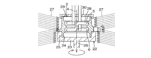
- FIG. 3 is a cross-sectional view showing an example of a step of heat-treating the inner shaft 3 using an example of the cooling device of the present invention in the heat treatment method for the rolling bearing device for wheels of the present invention.
- the cooling device 31 used in this example holds the inner shaft 3 with the outer peripheral surface having the raceway surface 13 up and the flange 19 down, and holds the shaft of the held inner shaft 3.
- a holding portion 32 that can rotate in the circumferential direction about A is included.
- the holding portion 32 protrudes upward from the upper surface of the bottom plate 33 and the bottom plate 33, abuts against the lower side surface of the flange 19 in the drawing, and opens a gap between the flange 19 and the bottom plate 33.
- a cylindrical receiving portion 34 is provided.
- the receiving part 34 has an inner diameter of the cylinder larger than an outer diameter of the wax part 21, and a protruding height from the upper surface of the bottom plate 33 is set higher than the height of the wax part 21 in the axis A direction. . Therefore, in a state where the flange 19 is supported by the receiving portion 34, the wax portion 21 is inserted into the cylinder of the receiving portion 34 and is supported in a state where a gap is provided between the bottom plate 33.
- the holding portion 32 is formed integrally with the peripheral edge of the bottom plate 33 and is brought into contact with the outer periphery of the flange 19 supported by the receiving portion 34 so as to partition the gap between the flange 19 and the bottom plate 33 from the outside.
- a rotating shaft 36 attached to the lower surface of the bottom plate 33.
- the protruding portion 35 and the rotating shaft 36 are provided coaxially so that the axis A of the inner shaft 3 coincides with the central axis of the rotating shaft 36 in a state where the protruding portion 35 is in contact with the outer periphery of the flange 19. .
- a through hole 37 that connects the inside and outside of the cylinder is formed at the base of the receiving portion 34, and a through hole 38 that connects between a water supply means (not shown) and the upper surface of the bottom plate 33 is formed in the rotating shaft 36. ing.
- the flange 19 passes through the through hole 38, the gap between the receiving portion 34, the gap between the wax portion 21 and the bottom plate 33, the through hole 37, and the outside of the receiving portion 34, as indicated by the dashed arrows in the drawing.
- the flow path of the water 27 reaching the spline hole 39 to which the bolt 20 is attached is configured.
- a receiving tool 40 for preventing shaft runout rotating around the axis A in a state fitted to the end 18 is attached.
- a high-frequency coil 41 for induction heating is extrapolated to the inner shaft 3.
- the winding diameter is set to a diameter that can be extrapolated to the inner shaft 3 and as close as possible to the raceway surface 13, and the number of turns in the axis A direction is the number of rows of the raceway surface 13.
- a single winding is used in accordance with (one row).
- the high frequency coil 41 is connected to a high frequency power source (not shown).
- the temperature of the induction heating is set to a temperature at which the steel material forming the region of the inner shaft 3 exhibits an austenite phase, and when the temperature reaches the temperature and cools after a predetermined time has passed, the steel material forming the region undergoes martensitic transformation. To be quenched.
- the flange 19 and the wax part 21 of the inner shaft 3 are continuously cooled by the water 27 continuously supplied through the flow path. Generation
- the productivity of the rolling bearing device 1 for the inner shaft 3 and thus the wheel rolling bearing device 1 can be improved by the amount that the process can be omitted.
- the amount of steel necessary for manufacturing the inner shaft 3 since it is not necessary to form the work on which the inner shaft 3 becomes a little larger in consideration of the amount of turning after heat treatment, the amount of steel necessary for manufacturing the inner shaft 3, energy required for transportation, storage It is possible to reduce the space required for the process.
- the occurrence of quenching unevenness can be suppressed, and the thickness and spread of the cured layer formed by the heat treatment can be made uniform.
- the inner shaft 3 is dried as necessary, and then assembled in combination with the rolling elements 4, the outer ring 2, and the bearing ring 14 in the procedure described above, the wheel rolling bearing device 1 shown in FIG. Manufactured.
- the outer ring 2 subjected to the heat treatment in FIG. 2 and the inner shaft 3 subjected to the tempering process in FIG. 3 may be combined. In that case, the productivity of the wheel rolling bearing device 1 can be further improved.
- the present invention is not limited to the above embodiments, and various modifications can be made within the scope of the claims.
- the high frequency coil 28 is fixed and the outer ring 2 is rotated to perform heat treatment, but conversely, the outer ring 2 may be fixed and the high frequency coil 28 may be rotated to perform heat treatment. And the high frequency coil 28 may be rotated together for heat treatment.
- the rotation direction and the rotation speed of the outer ring 2 and the high-frequency coil 28 may be different so that the outer ring 2 and the high-frequency coil 28 rotate relative to each other.
- the high frequency coil 41 is fixed and the inner shaft 3 is rotated to perform heat treatment, but conversely, the inner shaft 3 may be fixed and the high frequency coil 41 may be rotated to perform heat treatment.
- the inner shaft 3 and the high-frequency coil 41 may be rotated together for heat treatment.
- the rolling bearing device for a wheel manufactured according to the present invention is not limited to that shown in FIG. 1, and both conventional two-row raceway surfaces are formed on a raceway separate from the inner shaft 3.
- the two orbital track surfaces currently being developed may be formed directly on the outer peripheral surface of the inner shaft 3.
- the raceway surface can be heat-treated in a state where an outer ring whose raceway surface is arbitrarily arranged in accordance with the arrangement of the raceway surface is immersed in water.
Landscapes
- Engineering & Computer Science (AREA)
- Chemical & Material Sciences (AREA)
- Mechanical Engineering (AREA)
- Materials Engineering (AREA)
- Crystallography & Structural Chemistry (AREA)
- Thermal Sciences (AREA)
- Physics & Mathematics (AREA)
- Metallurgy (AREA)
- Organic Chemistry (AREA)
- General Engineering & Computer Science (AREA)
- Manufacturing & Machinery (AREA)
- Rolling Contact Bearings (AREA)
- Heat Treatment Of Articles (AREA)
Abstract
Description
外輪2の筒の内周には、転動体4を転動可能に支持する複列(図では2列)の軌道面5、6が形成されている。また筒の外周には、その周方向の複数箇所(図では1箇所のみ記載している)から筒の径方向外方へ向けて突設された、懸架装置への取り付けのための複数個の突出部7を有するフランジ8が、前記筒と一体に形成されている。 FIG. 1 is a cross-sectional view showing an example of a rolling bearing
On the inner periphery of the
内軸3には、前記内軸3の径方向外方へ向けて突設された、車輪やブレーキディスク等を取り付けるためのフランジ19が一体に形成されている。またフランジ19の、軌道面13が形成された側と反対側の側面には、前記側面から内軸3の軸方向に突設させて、ブレーキディスクを嵌め合わせるための筒状のいんろう部21が一体に形成されている。 A
The
前記内軸3には、いんろう部21をブレーキディスクに嵌め合わせた状態で、フランジ19の、図において左側の側面に、前記ブレーキディスクと車輪とが取り付けられるため、前記側面ができる限り平面であると共に、いんろう部21に歪みがないことが求められる。ところが、前記軌道面13を熱処理すると、フランジ19に歪みを生じて、前記側面の平面性が低下したり、いんろう部21が歪んだりするおそれがある。 The same applies to the
Since the brake disc and the wheel are attached to the left side surface of the
外輪の筒の開口に嵌め合わされる嵌め合い部を有するコンセントリングを2つ用意し、それぞれのコンセントリングの嵌め合い部を、外輪の筒の両側の開口に嵌め合わせた状態で熱処理をして、ワークの歪みを抑制することが提案されている。 Further, if the heat of the heat treatment is conducted non-uniformly to the non-heated region of the work or the work is cooled non-uniformly, uneven hardening may occur. That is, the thickness in the depth direction and the spread in the surface direction of the hardened layer formed by heat treatment vary, and particularly in the
Prepare two outlet rings with fitting parts that fit into the opening of the outer ring cylinder, and heat-treat each fitting part of the outer ring with the opening on both sides of the outer ring cylinder, It has been proposed to suppress workpiece distortion.
軌道面(13)を有する外周面および車輪を取り付けるフランジ(19)が一体に形成され、前記外輪と同軸に配置される内軸(3)とを備える車輪用転がり軸受装置(1)の軌道面に対する熱処理方法であって、
前記軌道面を加熱して硬化層を形成する際に、加熱中から加熱後までの所定時間に亘って、加熱している軌道面の近傍領域を水で冷却し続けることを特徴とする車輪用転がり軸受装置の熱処理方法を提供するものである(請求項1)。なお、カッコ内の英数字は、後述の実施の形態における対応構成要素等を表す。 In order to achieve the above object, the present invention has an outer ring (2) having a cylindrical shape and having raceway surfaces (5) and (6) formed on the inner periphery thereof,
A raceway surface of a rolling bearing device (1) for a wheel comprising an outer peripheral surface having a raceway surface (13) and a flange (19) for attaching a wheel, and an inner shaft (3) arranged coaxially with the outer ring. A heat treatment method for
When the raceway surface is heated to form a hardened layer, the area near the heated raceway surface is continuously cooled with water for a predetermined time from heating to after heating. A heat treatment method for a rolling bearing device is provided (claim 1). In addition, alphanumeric characters in parentheses represent corresponding components in the embodiments described later.
そのため、外輪が熱処理によって異状変形して全体に大きな歪みを生じるのを防止でき、熱処理後の外輪をさらに旋削して歪みを是正する工程を省略しても、前記外輪に要求される寸法精度を出すことが可能となる。 According to the present invention, in the case of the outer ring, heat treatment of the outer ring or the inner shaft is continued in the vicinity of the raceway surface being heated with water for a predetermined time from heating to after heating. It is possible to suppress the occurrence of internal stress in the outer ring due to non-uniform conduction to the non-heated region. Moreover, the entire outer ring can be uniformly and uniformly cooled only by stopping the heating.
Therefore, it is possible to prevent the outer ring from deforming due to heat treatment and causing a large distortion on the whole, and even if the process of further turning the outer ring after the heat treatment to correct the distortion is omitted, the dimensional accuracy required for the outer ring is improved. It becomes possible to put out.
したがって、旋削の工程を省略できる分、外輪や内軸の、ひいては車輪用転がり軸受装置の生産性を向上できる。また外輪や内軸のもとになるワークを、熱処理後の旋削分等を考慮して少し大きめに形成する必要もなくなるため、前記外輪や内軸の製造に要する鋼材の量、輸送に要するエネルギー、保管に要するスペース等を、いずれも低減できる。 Further, in the case of the inner shaft, the flange can be uniformly cooled, and the occurrence of the distortion of the flange due to the internal stress and the distortion of the enamel portion accompanying it can be suppressed. Therefore, even if the step of correcting the distortion by further turning the side surface of the flange and the heat-treated flange is omitted, the flatness required for the side surface can be obtained and the dimensional accuracy of the heat-treated portion can be obtained. It becomes possible.
Therefore, the productivity of the outer ring, the inner shaft, and thus the rolling bearing device for the wheel can be improved as much as the turning process can be omitted. In addition, it is not necessary to form the workpiece that becomes the outer ring and inner shaft slightly larger in consideration of the turning after heat treatment, etc., so the amount of steel required for manufacturing the outer ring and inner shaft and the energy required for transportation Any space required for storage can be reduced.
なお、外輪の軌道面をできるだけ均一に熱処理することを考慮すると、誘導加熱のための高周波コイル(28)を筒状の外輪内に挿入して、内周の軌道面に対向させた状態で、前記外輪を筒の軸(A)を中心として高周波コイルに対して周方向に相対回転させると共に、前記外輪の外周面全体に水(27)を噴きつけて冷却しながら、前記高周波コイルに通電して軌道面を加熱し、加熱終了後も一定時間冷却を行うのが好ましい(請求項2)。 Moreover, the occurrence of quenching unevenness is suppressed, and the thickness and spread of the hardened layer formed by the heat treatment can be made uniform, and particularly in the outer ring, the hardened layer partially reaches the outer peripheral surface of the cylinder, It is also possible to prevent the surface from being discolored unevenly.
In consideration of heat-treating the outer ring raceway surface as uniformly as possible, a high-frequency coil (28) for induction heating is inserted into the cylindrical outer ring and is opposed to the inner raceway surface. The outer ring is rotated relative to the high-frequency coil in the circumferential direction around the axis (A) of the cylinder, and the high-frequency coil is energized while spraying water (27) on the entire outer peripheral surface of the outer ring and cooling it. It is preferable to heat the raceway surface and cool for a predetermined time after the heating is finished.
図1は、先に説明したように車輪用転がり軸受装置1の一例を示す断面図である。図1を参照して、この例の車輪用転がり軸受装置1は、筒状の外輪2と、前記筒に挿通されて外輪2と軸Aを中心として同軸に配置された内軸3と、前記外輪2と内軸3との間に介在された複数個の転動体4とを備えている。 Embodiments of the present invention will be specifically described below with reference to the drawings.
FIG. 1 is a cross-sectional view showing an example of a wheel rolling
内軸3の小径部12の端部18は、車輪用転がり軸受装置1の組み立て前には、図中に破線で示すように小径部12と同径の筒状に形成されている。 The
The
次いで図中に実線で示すように端部18をかしめることで、軌道輪14を内軸3に固定して車輪用転がり軸受装置1を組み立てると、前記転動体4、軌道面5、6および軌道面13、15によって複列スラストアンギュラ玉軸受が構成されて、内軸3が外輪2に対して、軸Aを中心として回転自在に支持される。 In order to assemble the rolling
Next, as shown by the solid line in the figure, the
また内軸3は、やはり従来同様に、前記鋼材を熱間鍛造加工等して図1に示す形状に形成し、次いで軌道面13を熱処理して、前記軌道面13を含む領域に所定の厚みを有する硬化層を形成した後、必要に応じて表面を研磨して製造される。 The
The
図2は、前記本発明の車輪用転がり軸受装置の熱処理方法のうち、外輪2の熱処理の工程の一例を示す断面図である。図2を参照して、この例では、前記外輪2を保持して回転するターンテーブル22を用意する。 At this time, in the heat treatment method for the rolling bearing device for a wheel of the present invention, in the heat treatment of the
FIG. 2 is a cross-sectional view showing an example of the heat treatment process for the
誘導加熱の温度は、周知のように外輪2の前記領域を形成する鋼材がオーステナイト相を呈する温度に設定し、前記温度に達して一定時間経過した後に冷却すると、前記領域を形成する鋼材がマルテンサイト変態して焼入れされる。
この際、本発明では、外輪2の外周面全体を、熱処理の間、水27を噴きつけて継続的に冷却しているため、前記熱が非加熱領域に不均一に伝導して外輪2に内部応力が発生するのを抑制できる。また加熱を停止した後も一定時間の間、水27を噴きつけ続けることで、外輪2の全体を同時に、均一に冷却できる。 An additive such as a water-soluble polymer may be added to the
As is well known, the temperature of the induction heating is set to a temperature at which the steel material forming the region of the
At this time, in the present invention, the entire outer peripheral surface of the
熱処理後は外輪2を必要に応じて乾燥させた後、先に説明した手順で転動体4、内軸3、および軌道輪14と組み合わせて組み立てると、図1に示す車輪用転がり軸受装置1が製造される。 In addition, the occurrence of quenching unevenness is suppressed, the thickness and spread of the cured layer formed by the heat treatment can be made uniform, and the cured layer partially reaches the outer peripheral surface of the cylinder, Uneven discoloration can also be prevented.
After the heat treatment, the
突出部35および回転軸36は、前記突出部35をフランジ19の外周に当接させた状態で、内軸3の軸Aが回転軸36の中心軸と一致するように同軸に設けられている。また受部34の基部には筒の内外を繋ぐ通孔37が形成され、回転軸36内には、図示しない水の供給手段と、底板33の上面との間を繋ぐ通孔38が形成されている。これにより、図中に破線の矢印で示すように通孔38、受部34の筒内、いんろう部21と底板33との隙間、通孔37、および受部34の筒外を通して、フランジ19の、ボルト20が取り付けられるスプライン孔39に達する水27の流路が構成されている。 The holding
The protruding
この際、図の例では、内軸3のフランジ19といんろう部21とを、共に流路を通して連続的に供給される水27によって継続的に冷却しているため、内部応力によるフランジ19の歪みと、それに伴ういんろう部21の歪みとが発生するのを抑制できる。そのため、熱処理後のフランジ19の側面やいんろう部21をさらに旋削して歪みを是正する工程を省略しても、前記側面に要求される平面性を出すと共に、いんろう部21の寸法精度を出すことが可能となる。 The temperature of the induction heating is set to a temperature at which the steel material forming the region of the
At this time, in the example shown in the figure, the
また、本発明によって製造される車輪用転がり軸受装置は、図1のものには限定されず、従来の、2列の軌道面が共に、内軸3とは別体の軌道輪に形成されたものであってもよいし、現在、開発が進められている、2列の軌道面が共に、内軸3の外周面に直接に形成されたものであってもよい。前記軌道面の配置に合わせて軌道面を任意の配置とした外輪を水に浸漬した状態で、前記軌道面を熱処理することができる。 Similarly, in FIG. 3, the
Further, the rolling bearing device for a wheel manufactured according to the present invention is not limited to that shown in FIG. 1, and both conventional two-row raceway surfaces are formed on a raceway separate from the
Claims (4)
- 筒状をし、その内周に軌道面が形成された外輪と、
軌道面を有する外周面および車輪を取り付けるフランジが一体に形成され、前記外輪と同軸に配置される内軸とを備える車輪用転がり軸受装置の軌道面に対する熱処理方法であって、
前記軌道面を加熱して硬化層を形成する際に、加熱中から加熱後までの所定時間に亘って、加熱している軌道面の近傍領域を水で冷却し続けることを特徴とする車輪用転がり軸受装置の熱処理方法。 An outer ring having a cylindrical shape and a raceway surface formed on the inner periphery thereof;
A heat treatment method for a raceway surface of a rolling bearing device for a wheel comprising an outer peripheral surface having a raceway surface and a flange for attaching a wheel integrally formed, and an inner shaft disposed coaxially with the outer ring,
When the raceway surface is heated to form a hardened layer, the area near the heated raceway surface is continuously cooled with water for a predetermined time from heating to after heating. A heat treatment method for a rolling bearing device. - 誘導加熱のための高周波コイルを筒状の外輪内に挿入して、内周の軌道面に対向させた状態で、前記外輪を筒の軸を中心として高周波コイルに対して周方向に相対回転させると共に、前記外輪の外周面全体に水を噴きつけて冷却しながら、前記高周波コイルに通電して軌道面を加熱し、加熱終了後も一定時間冷却を行うことを特徴とする請求項1に記載の車輪用転がり軸受装置の熱処理方法。 A high-frequency coil for induction heating is inserted into a cylindrical outer ring, and the outer ring is rotated relative to the high-frequency coil in the circumferential direction around the axis of the cylinder with the inner ring facing the raceway surface. In addition, while spraying water on the entire outer peripheral surface of the outer ring and cooling, the high-frequency coil is energized to heat the raceway surface, and cooling is performed for a certain time after the heating is finished. Heat treatment method for rolling bearing device for wheels.
- 誘導加熱のための高周波コイルを内軸の軌道面に対向させ、前記内軸をその軸を中心として高周波コイルに対して周方向に相対回転させると共に、前記内軸のフランジを水と接触させて冷却しながら、前記高周波コイルに通電して軌道面を加熱し、加熱終了後も一定時間冷却を行うことを特徴とする請求項1に記載の車輪用転がり軸受装置の熱処理方法。 A high frequency coil for induction heating is opposed to the raceway surface of the inner shaft, the inner shaft is rotated relative to the high frequency coil in the circumferential direction around the axis, and the flange of the inner shaft is brought into contact with water. 2. The heat treatment method for a rolling bearing device for a wheel according to claim 1, wherein, while cooling, the high-frequency coil is energized to heat the raceway surface, and cooling is performed for a predetermined time after the heating is finished.
- 軌道面を有する外周面および車輪を取り付けるフランジが一体に形成された車輪用転がり軸受装置の内軸を、軌道面を有する外周面を上、フランジを下にした状態で保持すると共に、保持した内軸の軸を中心として周方向に回転可能な保持部を含み、前記保持部は、保持したフランジの下方の側面に水を供給し、前記側面に接触させてフランジを冷却した後、外部に流出させる水の流路を有することを特徴とする内軸の冷却装置。 The inner shaft of the rolling bearing device for wheels, in which the outer peripheral surface having the raceway surface and the flange to which the wheel is attached is integrally formed, is held with the outer peripheral surface having the raceway surface facing up and the flange facing down. A holding portion that can rotate in a circumferential direction around the axis of the shaft, the holding portion supplies water to a lower side surface of the held flange, cools the flange by contacting the side surface, and then flows out to the outside A cooling device for an inner shaft, characterized by having a water flow path.
Priority Applications (2)
| Application Number | Priority Date | Filing Date | Title |
|---|---|---|---|
| CN2009801146370A CN102016084B (en) | 2008-04-25 | 2009-04-24 | Heat treatment method for rolling bearing device for wheel and cooling device for inner shaft |
| US12/736,614 US20110036830A1 (en) | 2008-04-25 | 2009-04-24 | Heat treating method of rolling bearing device for wheel and cooling unit for inner shaft |
Applications Claiming Priority (2)
| Application Number | Priority Date | Filing Date | Title |
|---|---|---|---|
| JP2008-116228 | 2008-04-25 | ||
| JP2008116228A JP5365831B2 (en) | 2008-04-25 | 2008-04-25 | Heat treatment method for wheel rolling bearing device and cooling device for inner shaft |
Publications (1)
| Publication Number | Publication Date |
|---|---|
| WO2009131211A1 true WO2009131211A1 (en) | 2009-10-29 |
Family
ID=41216937
Family Applications (1)
| Application Number | Title | Priority Date | Filing Date |
|---|---|---|---|
| PCT/JP2009/058162 WO2009131211A1 (en) | 2008-04-25 | 2009-04-24 | Heat treatment method for rolling bearing device for wheel and cooling device for inner shaft |
Country Status (4)
| Country | Link |
|---|---|
| US (1) | US20110036830A1 (en) |
| JP (1) | JP5365831B2 (en) |
| CN (1) | CN102016084B (en) |
| WO (1) | WO2009131211A1 (en) |
Families Citing this family (2)
| Publication number | Priority date | Publication date | Assignee | Title |
|---|---|---|---|---|
| CN104313274B (en) * | 2014-11-12 | 2016-04-20 | 中南大学 | A kind of aluminium alloy annular element spray quench equipment and using method thereof |
| CN108546802B (en) * | 2018-05-23 | 2019-11-22 | 燕山大学 | A kind of inner chamber body part underwater electromagnetic annealing device and method |
Citations (4)
| Publication number | Priority date | Publication date | Assignee | Title |
|---|---|---|---|---|
| JPS60159114A (en) * | 1984-01-27 | 1985-08-20 | High Frequency Heattreat Co Ltd | Method and device for low strain hardening of collared cylindrical body |
| JP2006291250A (en) * | 2005-04-06 | 2006-10-26 | Nsk Ltd | Rolling bearing unit for wheel supporting |
| JP2008045718A (en) * | 2006-08-21 | 2008-02-28 | Nsk Ltd | Bearing unit |
| JP2008127666A (en) * | 2006-11-24 | 2008-06-05 | Ntn Corp | Heat-treatment method for outside member in bearing apparatus for wheel |
Family Cites Families (6)
| Publication number | Priority date | Publication date | Assignee | Title |
|---|---|---|---|---|
| US2167798A (en) * | 1935-08-19 | 1939-08-01 | Ohio Crankshaft Co | Apparatus for heat treating gears and the like |
| US4855551A (en) * | 1986-06-25 | 1989-08-08 | Tocco, Inc. | Method and apparatus for hardening gears |
| CN100347459C (en) * | 2002-07-15 | 2007-11-07 | 日本精工株式会社 | Rolling bearing unit for supporting wheel |
| JP2005188599A (en) * | 2003-12-25 | 2005-07-14 | Ntn Corp | Bearing device for wheel |
| JP2006077268A (en) * | 2004-09-07 | 2006-03-23 | Nsk Ltd | Method for producing track-ring in hub unit, and track-ring in hub unit |
| EP2599640B1 (en) * | 2006-08-07 | 2014-12-10 | NSK Ltd. | Bearing unit and method for producing a raceway ring member for a bearing unit |
-
2008
- 2008-04-25 JP JP2008116228A patent/JP5365831B2/en active Active
-
2009
- 2009-04-24 WO PCT/JP2009/058162 patent/WO2009131211A1/en active Application Filing
- 2009-04-24 CN CN2009801146370A patent/CN102016084B/en active Active
- 2009-04-24 US US12/736,614 patent/US20110036830A1/en not_active Abandoned
Patent Citations (4)
| Publication number | Priority date | Publication date | Assignee | Title |
|---|---|---|---|---|
| JPS60159114A (en) * | 1984-01-27 | 1985-08-20 | High Frequency Heattreat Co Ltd | Method and device for low strain hardening of collared cylindrical body |
| JP2006291250A (en) * | 2005-04-06 | 2006-10-26 | Nsk Ltd | Rolling bearing unit for wheel supporting |
| JP2008045718A (en) * | 2006-08-21 | 2008-02-28 | Nsk Ltd | Bearing unit |
| JP2008127666A (en) * | 2006-11-24 | 2008-06-05 | Ntn Corp | Heat-treatment method for outside member in bearing apparatus for wheel |
Also Published As
| Publication number | Publication date |
|---|---|
| CN102016084A (en) | 2011-04-13 |
| CN102016084B (en) | 2013-03-20 |
| US20110036830A1 (en) | 2011-02-17 |
| JP5365831B2 (en) | 2013-12-11 |
| JP2009263734A (en) | 2009-11-12 |
Similar Documents
| Publication | Publication Date | Title |
|---|---|---|
| WO2012098988A1 (en) | Method for manufacturing bearing ring, bearing ring, and rolling bearing | |
| JP5665564B2 (en) | Manufacturing method of bearing ring | |
| JP5773348B2 (en) | Method of manufacturing bearing ring, bearing ring and rolling bearing | |
| JP4178980B2 (en) | Method for heat treatment of annular member | |
| WO2017073325A1 (en) | Method for manufacturing bearing ring, and multi-row tapered roller bearing and manufacturing method therefor | |
| JP5557235B2 (en) | Heat treatment method for ring-shaped member, method for manufacturing ring-shaped member | |
| WO2009131211A1 (en) | Heat treatment method for rolling bearing device for wheel and cooling device for inner shaft | |
| WO2017203915A1 (en) | Heat treatment method for ring-shaped member, manufacturing method for ring-shaped member, bearing ring of roller bearing, and roller bearing | |
| JP2015180783A (en) | Bearing ring and method of producing rolling bearing | |
| JP5455031B2 (en) | Manufacturing method of bearing ring and manufacturing method of rolling bearing | |
| JP5534403B2 (en) | Bearing rings and rolling bearings | |
| JP5773349B2 (en) | Method of manufacturing bearing ring and rolling bearing | |
| JP2013167027A (en) | Heat treatment method for rolling bearing device for wheel | |
| JP2014095154A (en) | Heat treatment method for ring-shaped member, method for producing ring-shaped member, ring-shaped member, bearing ring of rolling bearing, and rolling bearing | |
| JP2009263733A (en) | Method for working outer-ring | |
| JP2009263734A5 (en) | ||
| WO2017199872A1 (en) | Method for heat-treating ring-shaped member, method for manufacturing ring-shaped member, raceway of rolling bearing, and rolling bearing | |
| JP2015187310A (en) | Bearing ring production method, bearing ring, and rolling bearing | |
| JP2015193936A (en) | Bearing ring and method of producing rolling bearing | |
| JP6072145B2 (en) | Manufacturing method of bearing ring | |
| JP6178365B2 (en) | Manufacturing method of bearing ring, cylindrical roller bearing and tapered roller bearing | |
| WO2017073327A1 (en) | Multi-row tapered roller bearing, and method for manufacturing bearing ring and multi-row tapered roller bearing | |
| JP2014025097A (en) | Method for manufacturing bearing ring, bearing ring and rolling bearing | |
| JP2008128420A (en) | Heat treatment method for outward member of wheel bearing device | |
| JP2017082300A (en) | Manufacturing method of bearing ring and double row tapered roller bearing |
Legal Events
| Date | Code | Title | Description |
|---|---|---|---|
| WWE | Wipo information: entry into national phase |
Ref document number: 200980114637.0 Country of ref document: CN |
|
| 121 | Ep: the epo has been informed by wipo that ep was designated in this application |
Ref document number: 09735788 Country of ref document: EP Kind code of ref document: A1 |
|
| WWE | Wipo information: entry into national phase |
Ref document number: 12736614 Country of ref document: US |
|
| NENP | Non-entry into the national phase |
Ref country code: DE |
|
| 122 | Ep: pct application non-entry in european phase |
Ref document number: 09735788 Country of ref document: EP Kind code of ref document: A1 |