JP5455031B2 - Manufacturing method of bearing ring and manufacturing method of rolling bearing - Google Patents
Manufacturing method of bearing ring and manufacturing method of rolling bearing Download PDFInfo
- Publication number
- JP5455031B2 JP5455031B2 JP2009273388A JP2009273388A JP5455031B2 JP 5455031 B2 JP5455031 B2 JP 5455031B2 JP 2009273388 A JP2009273388 A JP 2009273388A JP 2009273388 A JP2009273388 A JP 2009273388A JP 5455031 B2 JP5455031 B2 JP 5455031B2
- Authority
- JP
- Japan
- Prior art keywords
- manufacturing
- mass
- rolling
- bearing
- region
- Prior art date
- Legal status (The legal status is an assumption and is not a legal conclusion. Google has not performed a legal analysis and makes no representation as to the accuracy of the status listed.)
- Expired - Fee Related
Links
Images


Classifications
-
- Y—GENERAL TAGGING OF NEW TECHNOLOGICAL DEVELOPMENTS; GENERAL TAGGING OF CROSS-SECTIONAL TECHNOLOGIES SPANNING OVER SEVERAL SECTIONS OF THE IPC; TECHNICAL SUBJECTS COVERED BY FORMER USPC CROSS-REFERENCE ART COLLECTIONS [XRACs] AND DIGESTS
- Y02—TECHNOLOGIES OR APPLICATIONS FOR MITIGATION OR ADAPTATION AGAINST CLIMATE CHANGE
- Y02P—CLIMATE CHANGE MITIGATION TECHNOLOGIES IN THE PRODUCTION OR PROCESSING OF GOODS
- Y02P10/00—Technologies related to metal processing
- Y02P10/25—Process efficiency
Description
本発明は軌道輪の製造方法および転がり軸受の製造方法に関し、より特定的には、焼入装置の製作コストを抑制しつつ、高周波焼入によって焼入硬化層を転走面に沿って全周にわたって均質に形成するとともに、高周波焼入によって焼入硬化層を嵌め合い面に沿って形成することが可能な軌道輪および転がり軸受の製造方法に関するものである。 The present invention relates to a method of manufacturing a bearing ring and a method of manufacturing a rolling bearing, and more specifically, while suppressing the manufacturing cost of the quenching device, the quench hardened layer is formed along the rolling surface by induction hardening. And a method for manufacturing a bearing ring and a rolling bearing capable of forming a hardened hardened layer along a mating surface by induction hardening.
鋼からなる転がり軸受の軌道輪に対する焼入硬化処理として、高周波焼入が採用される場合がある。この高周波焼入は、軌道輪を炉内で加熱した後、油などの冷却液中に浸漬する一般的な焼入硬化処理に比べて、設備を簡略化できるとともに、短時間での熱処理が可能となるなどの利点を有している。 Induction hardening may be employed as a hardening treatment for the rolling rings of rolling bearings made of steel. This induction hardening can simplify the equipment and heat treatment in a short time compared to the general quench hardening process in which the race is heated in the furnace and then immersed in a coolant such as oil. It has the advantage of becoming.
しかし、高周波焼入において、軌道輪の転走面に沿った焼入硬化すべき環状の領域を同時に加熱するためには、転走面に対向するように、当該軌道輪を誘導加熱するためのコイルなどの誘導加熱部材を配置する必要がある。そのため、大型の軌道輪を焼入硬化する場合、それに応じた大型のコイルや当該コイルに対応する大容量の電源が必要となり、焼入装置の製作コストが高くなるという問題がある。 However, in induction hardening, in order to simultaneously heat the annular region to be hardened and hardened along the raceway surface of the raceway, it is necessary to inductively heat the raceway so as to face the raceway surface. It is necessary to arrange an induction heating member such as a coil. For this reason, when quenching and hardening a large race, a large coil corresponding to that and a large-capacity power source corresponding to the coil are required, which increases the production cost of the quenching apparatus.
このような問題を回避する方策として、小型の誘導加熱コイルを用いた移動焼入が採用される場合がある。この移動焼入では、軌道輪において加熱すべき環状の領域の一部に対向して配置され、当該領域に沿って相対的に移動するコイルを用いて高周波誘導加熱を実施し、加熱された領域に対してコイルの通過直後に水などの冷却液を噴射することにより、当該領域を順次焼入硬化する。しかし、単にこの移動焼入を採用した場合、焼入が開始された領域(焼入開始領域)からコイルが一回りし、最後に焼入を実施すべき領域(焼入終了領域)を焼入硬化する際、焼入開始領域と焼入終了領域とが部分的に重複する。そのため、重複した領域が再焼入されることによる焼割れの発生が懸念される。また、上記重複した領域に隣接する領域は、焼入終了領域の加熱に伴ってA1点以下の温度に加熱されて焼戻されるため、硬度が低下するおそれもある。そのため、移動焼入が採用される場合、焼入開始領域と焼入終了領域との間に焼入を実施しない領域(ソフトゾーン)を残存させる対策が採られるのが一般的である。このソフトゾーンは、硬度が低いため降伏強度が低く、また耐摩耗性も不十分である。そのため、軌道輪にソフトゾーンを形成した場合、当該ソフトゾーンが負荷域とならないように配慮する必要がある。 As a measure for avoiding such a problem, there is a case where moving quenching using a small induction heating coil is employed. In this moving quenching, high-frequency induction heating is performed using a coil that is arranged to face a part of an annular region to be heated in the raceway and relatively moves along the region, and is heated. On the other hand, the region is sequentially hardened by jetting a coolant such as water immediately after passing through the coil. However, when this moving quenching is simply adopted, the coil turns once from the quenching start area (quenching start area) and finally quenches the area where quenching should be performed (quenching end area). When hardening, the quenching start area and the quenching end area partially overlap. For this reason, there is a concern about occurrence of quench cracks due to re-quenching of the overlapped region. The region adjacent to the overlapping region, since it is tempered by being heated to a temperature of less than 1 point A along with the heating of the quenching termination region, there is a possibility that the hardness is lowered. Therefore, when moving quenching is employed, it is common to take measures to leave a region (soft zone) where quenching is not performed between the quenching start region and the quenching end region. This soft zone has low yield strength due to low hardness, and insufficient wear resistance. Therefore, when a soft zone is formed on the race, it is necessary to consider that the soft zone does not become a load region.
これに対し、ソフトゾーンを形成する上記移動焼入を実施した後、ソフトゾーンに相当する領域を切除するとともに、当該領域に焼入を施した栓体を嵌め込む方法が提案されている(たとえば、特許文献1参照)。これにより、硬度の低いソフトゾーンが残存することを回避することができる。 On the other hand, after carrying out the above moving quenching to form a soft zone, a method has been proposed in which a region corresponding to the soft zone is excised and a hardened plug body is fitted in the region (for example, , See Patent Document 1). Thereby, it can avoid that the soft zone with low hardness remains.
また、軌道輪の周方向反対向きに移動する2つのコイルを用いて、ソフトゾーンの形成を回避する方法も提案されている(たとえば、特許文献2参照)。この方法では、2つのコイルが互いに隣接するように配置された状態で焼入を開始し、再度衝合する位置で焼入を終了することにより、ソフトゾーンの形成を回避しつつ、再焼入される領域の発生をも回避することができる。 In addition, a method of avoiding the formation of a soft zone by using two coils that move in opposite directions in the circumferential direction of the raceway has been proposed (see, for example, Patent Document 2). In this method, the quenching is started in a state where the two coils are arranged adjacent to each other, and the quenching is finished at a position where the two coils meet again, thereby avoiding the formation of a soft zone and re-quenching. It is also possible to avoid the occurrence of a region to be generated.
しかしながら、上記特許文献1に開示された方法では、軌道輪を製造するための工数が大幅に増加するという問題がある。また、上記特許文献2に開示された方法では、最後に焼入される領域に焼入硬化に伴う残留応力が集中し、熱処理ひずみや焼割れの発生が懸念される。 However, the method disclosed in Patent Document 1 has a problem that the number of man-hours for manufacturing the race is significantly increased. Further, in the method disclosed in Patent Document 2, the residual stress accompanying quench hardening is concentrated in the region that is finally quenched, and there is a concern about the occurrence of heat treatment distortion and quench cracking.
また、軌道輪が他の部材に対して嵌め込まれて使用される場合、当該他の部材に接触する面である嵌め合い面にも高い硬度が要求される場合がある。一方、転走面を含む領域に高周波焼入によって焼入硬化層(転走面焼入層)が形成された軌道輪において、嵌め合い面に高い硬度を付与するためには、嵌め合い面を含む領域に対しても焼入硬化層(嵌め合い面焼入層)を形成する必要がある。しかし、転走面焼入層と嵌め合い面焼入層とを同時に形成するためには、焼入装置の構造が複雑となり当該装置の製作コストが高くなるという問題がある。また、転走面焼入層および嵌め合い面焼入層の一方を形成した後、他方を形成するプロセスを採用した場合、先に形成された焼入層が後の焼入層の形成時における加熱により焼き戻され、硬度が低下するという問題が発生する。 Moreover, when a raceway ring is used by being fitted to another member, high hardness may be required for a fitting surface that is a surface in contact with the other member. On the other hand, in a race ring in which a hardened hardened layer (rolling surface hardened layer) is formed by induction hardening in a region including the rolling surface, in order to give the fitting surface high hardness, It is necessary to form a hardened hardened layer (fitting surface hardened layer) for the region to be included. However, in order to form the rolling surface quenching layer and the mating surface quenching layer at the same time, there is a problem that the structure of the quenching apparatus becomes complicated and the manufacturing cost of the apparatus increases. In addition, when one of the rolling surface quenching layer and the mating surface quenching layer is formed and then adopting the process of forming the other, the previously formed quenching layer is formed at the time of subsequent quenching layer formation. There arises a problem that the hardness is lowered due to tempering by heating.
そこで、本発明の目的は、焼入装置の製作コストを抑制しつつ、高周波焼入によって焼入硬化層を転走面に沿って全周にわたって均質に形成するとともに、転走面の硬度の低下を抑制しつつ嵌め合い面にも焼入硬化層を形成することが可能な転がり軸受の軌道輪および転がり軸受の製造方法を提供することである。 Accordingly, an object of the present invention is to form a quench-hardened layer uniformly along the rolling surface by induction hardening while reducing the manufacturing cost of the quenching device, and to reduce the hardness of the rolling surface. It is to provide a bearing ring for a rolling bearing and a method for manufacturing the rolling bearing capable of forming a hardened hardened layer on the mating surface while suppressing the above.
本発明に従った軌道輪の製造方法は、転がり軸受の軌道輪の製造方法である。この軌道輪の製造方法は、鋼から構成される成形体を準備する工程と、成形体において軌道輪の転走面となるべき環状領域の一部に面するように配置され、成形体を誘導加熱する誘導加熱部材を、環状領域の周方向に沿って相対的に回転させることにより、成形体にA1点以上の温度に加熱された環状の加熱領域を形成する工程と、加熱領域全体をMS点以下の温度に同時に冷却することにより、転走面焼入層を環状領域に沿って全周にわたって形成する工程と、成形体において軌道輪の嵌め合い面となるべき領域の一部に面するように配置され、成形体を誘導加熱する他の誘導加熱部材を、嵌め合い面となるべき領域の周方向に沿って相対的に移動させるとともに、当該他の誘導加熱部材を追動する冷却部材により、他の誘導加熱部材によって加熱された領域を冷却することで嵌め合い面焼入層を形成する工程とを備えている。 The method for manufacturing a bearing ring according to the present invention is a method for manufacturing a bearing ring for a rolling bearing. This method of manufacturing a bearing ring includes a step of preparing a molded body made of steel, and the molded body is arranged so as to face a part of an annular region to be a rolling surface of the bearing ring, thereby guiding the molded body. A process of forming an annular heating region heated to a temperature of one point A or more on the formed body by relatively rotating the induction heating member to be heated along the circumferential direction of the annular region, and the entire heating region By simultaneously cooling to a temperature not higher than the M S point, the process of forming the rolling surface hardened layer over the entire circumference along the annular region, and a part of the region to be the mating surface of the bearing ring in the molded body The other induction heating member that is arranged so as to face and induction-heats the molded body is relatively moved along the circumferential direction of the region to be the fitting surface, and the other induction heating member is driven. By cooling member, other induction heating member And a step of forming a mating surface hardened layer by cooling the heated region I.
本発明の軌道輪の製造方法においては、転走面となるべき環状領域の一部に面するように配置された誘導加熱部材が周方向に沿って相対的に回転することにより、成形体に加熱領域が形成される。そのため、軌道輪の外形形状に対して小さい誘導加熱部材を採用することが可能である。その結果、大型の軌道輪を焼入硬化する場合でも、焼入装置の製作コストを抑制することができる。また、本発明の軌道輪の製造方法においては、加熱領域全体がMS点以下の温度に同時に冷却される。そのため、焼入硬化層を転走面に沿って全周にわたって同時に形成することが可能となり、一部の領域に残留応力が集中することが抑制される。 In the method for manufacturing a raceway ring according to the present invention, the induction heating member arranged so as to face a part of the annular region to be a rolling surface relatively rotates along the circumferential direction, thereby forming a molded body. A heating region is formed. Therefore, it is possible to employ a small induction heating member with respect to the outer shape of the race. As a result, the manufacturing cost of the quenching device can be suppressed even when a large raceway is quenched and hardened. In the method for manufacturing a bearing ring according to the present invention, the entire heating region is simultaneously cooled to a temperature below the MS point. Therefore, it is possible to simultaneously form a hardened hardened layer along the rolling surface over the entire circumference, and the residual stress is suppressed from being concentrated in a part of the region.
さらに、本発明の軌道輪の製造方法においては、嵌め合い面となるべき領域の一部に面するように配置され、成形体を誘導加熱する他の誘導加熱部材を、嵌め合い面となるべき領域の周方向に沿って相対的に移動させるとともに、当該他の誘導加熱部材を追動する冷却部材により、他の誘導加熱部材によって加熱された領域を冷却することで嵌め合い面焼入層が形成される。嵌め合い面は、転走面とは異なり、必ずしも全周にわたって焼入硬化層を形成する必要はなく、周方向の一部に焼入硬化層が形成されない領域が形成されてもよい。そのため、上述のような移動焼入による嵌め合い面焼入層の形成が可能である。また、上記移動焼入においては、誘導加熱部材により加熱された領域が、加熱直後に冷却部材により冷却されるため、先に形成された転走面焼入層が嵌め合い面焼入層の形成時における加熱により焼き戻されて硬度が低下することも抑制される。 Furthermore, in the method for manufacturing a raceway ring according to the present invention, another induction heating member that is arranged so as to face a part of the region to be the fitting surface and induction-heats the molded body should be the fitting surface. The mating surface hardened layer is formed by cooling the region heated by the other induction heating member with the cooling member that moves the other induction heating member relative to each other along the circumferential direction of the region. It is formed. Unlike the rolling surface, the fitting surface does not necessarily need to form a hardened and hardened layer over the entire circumference, and a region where the hardened and hardened layer is not formed may be formed in a part of the circumferential direction. Therefore, it is possible to form a mating surface hardened layer by moving quenching as described above. Further, in the above moving quenching, since the region heated by the induction heating member is cooled by the cooling member immediately after the heating, the previously formed rolling surface quenching layer is fitted to form the surface quenching layer. It is also possible to prevent the hardness from being tempered by heating at the time, and to decrease the hardness.
このように、本発明の軌道輪の製造方法によれば、焼入装置の製作コストを抑制しつつ、高周波焼入によって焼入硬化層を転走面に沿って全周にわたって均質に形成するとともに、転走面の硬度の低下を抑制しつつ嵌め合い面にも焼入硬化層を形成することができる。 As described above, according to the method for manufacturing a bearing ring of the present invention, while suppressing the manufacturing cost of the quenching device, the quench hardening layer is uniformly formed along the rolling surface along the rolling surface by induction hardening. Further, it is possible to form a hardened and hardened layer on the mating surface while suppressing a decrease in hardness of the rolling surface.
なお、A1点とは鋼を加熱した場合に、鋼の組織がフェライトからオーステナイトに変態を開始する温度に相当する点をいう。また、Ms点とはオーステナイト化した鋼が冷却される際に、マルテンサイト化を開始する温度に相当する点をいう。 Note that the point A when heated steel refers to a point that the structure of the steel corresponds to the temperature to start the transformation from ferrite to austenite. Further, the M s point means a point corresponding to a temperature at which martensite formation starts when the austenitized steel is cooled.
上記軌道輪の製造方法においては、加熱領域を形成する工程よりも前に、成形体に焼ならし処理を実施する工程をさらに備えていてもよい。 The method for manufacturing a bearing ring may further include a step of performing a normalizing process on the molded body before the step of forming the heating region.
高周波焼入により転走面を含む領域および嵌め合い面を含む領域が部分的に焼入硬化されて製造される軌道輪においては、焼入硬化されない領域(非硬化領域)においても所定の強度を確保可能な硬度を有している必要がある。そして、非硬化領域において所定の硬度を確保するためには、高周波焼入処理前に成形体(軌道輪)全体に焼入処理を実施した後、さらに焼戻処理を実施してもよい。しかし、炭素含有量が比較的高く、かつ焼入性の高い成分組成を有する鋼が素材として採用される場合、焼割れが発生しやすいという問題がある。一方、そのような成分組成の鋼からなる成形体においては、焼ならし処理により十分な硬度を確保することができる。そのため、上記焼入および焼戻による硬度の確保に代えて、焼ならし処理を高周波焼入の前に実施しておくことにより、非硬化領域に適切な硬度を付与することができる。 In a raceway ring manufactured by induction hardening and a region including a rolling surface and a region including a mating surface being partially quenched and hardened, a predetermined strength is provided even in a region that is not hardened (non-hardened region). It is necessary to have sufficient hardness. And in order to ensure predetermined | prescribed hardness in a non-hardening area | region, after performing the quenching process to the whole molded object (track ring) before an induction hardening process, you may implement a tempering process further. However, when steel having a relatively high carbon content and a high hardenability component composition is adopted as a material, there is a problem that quench cracking is likely to occur. On the other hand, in a molded body made of steel having such a component composition, sufficient hardness can be ensured by normalizing treatment. Therefore, instead of securing the hardness by the quenching and tempering, an appropriate hardness can be imparted to the non-cured region by performing the normalizing treatment before the induction hardening.
上記軌道輪の製造方法においては、焼ならし処理を実施する工程では、成形体に気体とともに硬質の粒子が吹き付けられることにより、成形体が冷却されつつショットブラスト処理が実施されてもよい。 In the above-described method for manufacturing a bearing ring, in the step of performing the normalizing process, the shot blasting process may be performed while the molded body is cooled by spraying hard particles together with gas on the molded body.
これにより、焼ならし処理の際の衝風冷却と同時にショットブラスト処理を実施することができる。そのため、焼きならし処理の加熱によって成形体の表層部に生成したスケールが除去され、スケールの生成に起因した軌道輪の特性低下やスケールの生成による熱伝導率の低下が抑制される。 Thus, the shot blasting process can be performed simultaneously with the gust cooling at the normalizing process. Therefore, the scale generated in the surface layer portion of the compact is removed by the heating of the normalizing process, and the deterioration of the characteristics of the raceway due to the generation of the scale and the decrease of the thermal conductivity due to the generation of the scale are suppressed.
上記軌道輪の製造方法においては、軌道輪は複列の転走面を含んでいてもよい。この場合、転走面焼入層を形成する工程では、複列の加熱領域が同時にMS点以下の温度に冷却されることが好ましい。 In the above-described method for manufacturing a race, the race may include a double row rolling surface. In this case, in the step of forming a rolling surface hardened layer, it is preferable that the heating region of the double row is cooled M S point below the temperature at the same time.
軌道輪が複列の転走面を含む場合、一の転走面に転走面焼入層を形成した後、他の転走面に転走面焼入層を形成すると、先に形成された転走面焼入層が後に形成される転走面焼入層の形成に伴う加熱により焼戻され、硬度が低下する可能性がある。これに対し、複列の加熱領域が同時にMS点以下の温度に冷却されて転走面焼入層が形成されることにより、上記転走面焼入層の硬度の低下が回避される。 When the raceway includes double-row rolling surfaces, after forming a rolling surface hardened layer on one rolling surface, a rolling surface hardened layer on the other rolling surface is formed first. The rolled surface hardened layer may be tempered by the heating accompanying the formation of the rolled surface hardened layer to be formed later, and the hardness may decrease. In contrast, by heating areas of the double row is formed rolling surfaces hardened layer is cooled to M S point below the temperature at the same time, decrease in the hardness of the rolling surface hardening layer is avoided.
上記軌道輪の製造方法においては、加熱領域を形成する工程では、誘導加熱部材は、成形体の周方向に沿って相対的に2周以上回転してもよい。これにより、転走面の周方向における温度のばらつきを抑制し、均質な焼入硬化を実現することができる。 In the method for manufacturing a bearing ring, in the step of forming the heating region, the induction heating member may relatively rotate two or more times along the circumferential direction of the molded body. Thereby, the dispersion | variation in the temperature in the circumferential direction of a rolling surface can be suppressed, and homogeneous quench hardening can be implement | achieved.
上記軌道輪の製造方法においては、加熱領域を形成する工程では、誘導加熱部材は、成形体の周方向に沿って複数個配置されてもよい。これにより、転走面の周方向における温度のばらつきを抑制し、均質な焼入硬化を実現することができる。 In the above-described method for manufacturing a race, a plurality of induction heating members may be arranged along the circumferential direction of the molded body in the step of forming the heating region. Thereby, the dispersion | variation in the temperature in the circumferential direction of a rolling surface can be suppressed, and homogeneous quench hardening can be implement | achieved.
上記軌道輪の製造方法においては、加熱領域を形成する工程では、加熱領域の複数箇所の温度が測定されてもよい。これにより、転走面の周方向において均質な加熱が実現されていることを確認した上で急冷して焼入硬化処理を実施することができる。その結果、転走面の周方向において均質な焼入硬化を実現することができる。 In the method for manufacturing a race, the temperature at a plurality of locations in the heating region may be measured in the step of forming the heating region. Thereby, after confirming that homogeneous heating has been realized in the circumferential direction of the rolling surface, quenching and hardening can be performed. As a result, uniform quenching hardening can be realized in the circumferential direction of the rolling surface.
上記軌道輪の製造方法においては、成形体を準備する工程では、0.43質量%以上0.65質量%以下の炭素と、0.15質量%以上0.35質量%以下の珪素と、0.60質量%以上1.10質量%以下のマンガンと、0.30質量%以上1.20質量%以下のクロムと、0.15質量%以上0.75質量%以下のモリブデンとを含有し、残部鉄および不純物からなる鋼から構成される成形体が準備されてもよい。 In the method for manufacturing a bearing ring, in the step of preparing a molded body, 0.43% to 0.65% carbon, 0.15% to 0.35% silicon, Containing from 60 mass% to 1.10 mass% manganese, from 0.30 mass% to 1.20 mass% chromium, and from 0.15 mass% to 0.75 mass% molybdenum, A formed body made of steel composed of the remaining iron and impurities may be prepared.
また、上記軌道輪の製造方法においては、成形体を準備する工程では、0.43質量%以上0.65質量%以下の炭素と、0.15質量%以上0.35質量%以下の珪素と、0.60質量%以上1.10質量%以下のマンガンと、0.30質量%以上1.20質量%以下のクロムと、0.15質量%以上0.75質量%以下のモリブデンと、0.35質量%以上0.75質量%以下のニッケルとを含有し、残部鉄および不純物からなる鋼から構成される成形体が準備されてもよい。 Further, in the method of manufacturing the race, in the step of preparing the molded body, 0.43% to 0.65% carbon, 0.15% to 0.35% silicon, 0.60% by mass to 1.10% by mass manganese, 0.30% by mass to 1.20% by mass chromium, 0.15% by mass to 0.75% by mass molybdenum, A molded body that includes .35 mass% or more and 0.75 mass% or less of nickel and that is made of steel composed of the remaining iron and impurities may be prepared.
このような成分組成の鋼を素材として採用することにより、焼入硬化により十分に高い硬度を実現できるとともに、高い焼入性を確保しつつ焼割れを抑制することができる。 By adopting steel having such a component composition as a raw material, sufficiently high hardness can be realized by quench hardening, and quench cracking can be suppressed while ensuring high hardenability.
ここで、成形体を構成する鋼の成分範囲、すなわち製造される軌道輪を構成する鋼の成分範囲を上記の範囲とすることが好ましい理由について説明する。 Here, the reason why it is preferable to set the component range of steel constituting the formed body, that is, the component range of steel constituting the manufactured bearing ring, to the above range will be described.
炭素:0.43質量%以上0.65%質量%以下
炭素含有量は、焼入硬化後における軌道輪の転走面の硬度に大きな影響を与える。軌道輪を構成する鋼の炭素含有量が0.43質量%未満では、焼入硬化後における転走面に十分な硬度を付与することが困難となるおそれがある。一方、炭素含有量が0.65質量%を超えると、焼入硬化の際の割れの発生(焼割れ)が懸念される。そのため、炭素含有量は0.43質量%以上0.65%質量%以下とすることが好ましい。
Carbon: 0.43 mass% or more and 0.65% mass% or less The carbon content greatly affects the hardness of the raceway of the raceway after quench hardening. If the carbon content of the steel constituting the bearing ring is less than 0.43 mass%, it may be difficult to impart sufficient hardness to the rolling surface after quench hardening. On the other hand, when the carbon content exceeds 0.65% by mass, there is a concern about generation of cracks (quenching cracks) during quench hardening. Therefore, the carbon content is preferably 0.43% by mass or more and 0.65% by mass or less.
珪素:0.15質量%以上0.35質量%以下
珪素は、鋼の焼戻軟化抵抗の向上に寄与する。軌道輪を構成する鋼の珪素含有量が0.15質量%未満では、焼戻軟化抵抗が不十分となり、焼入硬化後の焼戻や、軌道輪の使用中における温度上昇により転走面の硬度が大幅に低下する可能性がある。一方、珪素含有量が0.35質量%を超えると、焼入前の素材の硬度が高くなり、素材を軌道輪に成形する際の冷間加工における加工性が低下するおそれがある。そのため、珪素含有量は0.15質量%以上0.35質量%以下とすることが好ましい。
Silicon: 0.15 mass% or more and 0.35 mass% or less Silicon contributes to the improvement of the temper softening resistance of steel. When the silicon content of the steel constituting the raceway is less than 0.15% by mass, the temper softening resistance becomes insufficient, and the rolling surface of the raceway surface is increased due to tempering after quench hardening and temperature rise during use of the raceway. Hardness can be significantly reduced. On the other hand, if the silicon content exceeds 0.35% by mass, the hardness of the material before quenching increases, and the workability in cold working when forming the material into a raceway ring may be reduced. Therefore, the silicon content is preferably 0.15% by mass or more and 0.35% by mass or less.
マンガン:0.60質量%以上1.10質量%以下
マンガンは、鋼の焼入性の向上に寄与する。マンガン含有量が0.60質量%未満では、この効果が十分に得られない。一方、マンガン含有量が1.10質量%を超えると、焼入前の素材の硬度が高くなり、冷間加工における加工性が低下する。そのため、マンガン含有量は0.60質量%以上1.10質量%以下とすることが好ましい。
Manganese: 0.60% by mass or more and 1.10% by mass or less Manganese contributes to improvement of hardenability of steel. If the manganese content is less than 0.60% by mass, this effect cannot be sufficiently obtained. On the other hand, if the manganese content exceeds 1.10% by mass, the hardness of the material before quenching increases, and the workability in cold working decreases. Therefore, the manganese content is preferably 0.60% by mass or more and 1.10% by mass or less.
クロム:0.30質量%以上1.20質量%以下
クロムは、鋼の焼入性の向上に寄与する。クロム含有量が0.30質量%未満では、この効果が十分に得られない。一方、クロム含有量が1.20質量%を超えると、素材コストが高くなるという問題が生じる。そのため、クロム含有量は0.30質量%以上1.20質量%以下とすることが好ましい。
Chromium: 0.30% by mass or more and 1.20% by mass or less Chromium contributes to improvement of hardenability of steel. If the chromium content is less than 0.30% by mass, this effect cannot be sufficiently obtained. On the other hand, when the chromium content exceeds 1.20% by mass, there arises a problem that the material cost increases. Therefore, the chromium content is preferably 0.30% by mass or more and 1.20% by mass or less.
モリブデン:0.15質量%以上0.75質量%以下
モリブデンも、鋼の焼入性の向上に寄与する。モリブデン含有量が0.15質量%未満では、この効果が十分に得られない。一方、モリブデン含有量が0.75質量%を超えると、素材コストが高くなるという問題が生じる。そのため、モリブデン含有量は0.15質量%以上0.75質量%以下とすることが好ましい。
Molybdenum: 0.15 mass% or more and 0.75 mass% or less Molybdenum also contributes to improving the hardenability of the steel. If the molybdenum content is less than 0.15% by mass, this effect cannot be sufficiently obtained. On the other hand, when the molybdenum content exceeds 0.75% by mass, there arises a problem that the material cost increases. Therefore, the molybdenum content is preferably 0.15% by mass or more and 0.75% by mass or less.
ニッケル:0.35質量%以上0.75質量%以下
ニッケルも、鋼の焼入性の向上に寄与する。ニッケルは、軌道輪の外形が大きい場合など、軌道輪を構成する鋼に特に高い焼入性が求められる場合に添加することができる。ニッケル含有量が0.35質量%未満では、焼入性向上の効果が十分に得られない。一方、ニッケル含有量が0.75質量%を超えると、焼入後における残留オーステナイト量が多くなり、硬さの低下、寸法安定性の低下などの原因となるおそれがある。そのため、ニッケルは軌道輪を構成する鋼に0.35質量%以上0.75質量%以下の範囲で添加されることが好ましい。
Nickel: 0.35 mass% or more and 0.75 mass% or less Nickel also contributes to improvement of hardenability of steel. Nickel can be added when particularly high hardenability is required for the steel constituting the bearing ring, such as when the outer shape of the bearing ring is large. If the nickel content is less than 0.35% by mass, the effect of improving hardenability cannot be obtained sufficiently. On the other hand, if the nickel content exceeds 0.75% by mass, the amount of retained austenite after quenching increases, which may cause a decrease in hardness and a decrease in dimensional stability. Therefore, it is preferable that nickel is added to the steel constituting the race in a range of 0.35 mass% to 0.75 mass%.
本発明に従った転がり軸受の製造方法は、軌道輪を準備する工程と、転動体を準備する工程と、軌道輪と転動体とを組み合わせて転がり軸受を組み立てる工程とを備えている。そして、軌道輪は、上記本発明の軌道輪の製造方法により製造されている。 The manufacturing method of a rolling bearing according to the present invention includes a step of preparing a bearing ring, a step of preparing a rolling element, and a step of assembling the rolling bearing by combining the bearing ring and the rolling element. And the bearing ring is manufactured by the manufacturing method of the bearing ring of the said invention.
軌道輪を上記本発明の軌道輪の製造方法により製造することにより、本発明の転がり軸受の製造方法によれば、高周波焼入によって焼入硬化層が転走面に沿って全周にわたって均質に形成されるとともに、転走面の硬度の低下を抑制しつつ嵌め合い面にも焼入硬化層が形成された軌道輪を備える転がり軸受を低コストで製造することができる。 By manufacturing the bearing ring by the above-described manufacturing method of the bearing ring of the present invention, according to the rolling bearing manufacturing method of the present invention, the hardened hardened layer is homogenized along the entire rolling surface by induction hardening. A rolling bearing provided with a bearing ring that is formed and has a hardened hardened layer formed on the mating surface while suppressing a decrease in hardness of the rolling surface can be manufactured at low cost.
上記転がり軸受の製造方法においては、上記転がり軸受は、風力発電装置において、ブレードに接続された主軸を主軸に隣接する部材に対して回転自在に支持する風力発電装置用転がり軸受として用いられるものであってもよい。上述のように、大型の軌道輪の転走面および嵌め合い面を含む領域に焼入硬化層を低コストで形成可能な本発明の転がり軸受の製造方法は、風力発電装置用転がり軸受の製造方法として好適である。 In the method of manufacturing a rolling bearing, the rolling bearing is used as a rolling bearing for a wind power generator that rotatably supports a main shaft connected to a blade with respect to a member adjacent to the main shaft in a wind power generator. There may be. As described above, the method of manufacturing a rolling bearing according to the present invention that can form a hardened hardened layer in a region including a rolling surface and a mating surface of a large-sized bearing ring at low cost is a method for manufacturing a rolling bearing for a wind turbine generator. It is suitable as a method.
以上の説明から明らかなように、本発明の軌道輪および転がり軸受の製造方法は、焼入装置の製作コストを抑制しつつ、高周波焼入によって焼入硬化層を転走面に沿って全周にわたって均質に形成するとともに、転走面の硬度の低下を抑制しつつ嵌め合い面にも焼入硬化層を形成することが可能な軌道輪および転がり軸受の製造方法を提供することができる。 As is apparent from the above description, the method of manufacturing the bearing ring and the rolling bearing according to the present invention reduces the manufacturing cost of the quenching device, and the quench hardening layer is formed along the rolling surface by induction hardening. It is possible to provide a method of manufacturing a bearing ring and a rolling bearing capable of forming a hardened and hardened layer on a mating surface while suppressing a decrease in hardness of the rolling surface.
以下、図面に基づいて本発明の実施の形態を説明する。なお、以下の図面において同一または相当する部分には同一の参照番号を付し、その説明は繰り返さない。 Hereinafter, embodiments of the present invention will be described with reference to the drawings. In the following drawings, the same or corresponding parts are denoted by the same reference numerals, and description thereof will not be repeated.
(実施の形態1)
まず、本発明の一実施の形態である実施の形態1について説明する。以下、軌道輪の製造方法として主に外輪の製造方法について説明するが、内輪についても同様に製造することができる。
(Embodiment 1)
First, Embodiment 1 which is one embodiment of the present invention will be described. Hereinafter, although the manufacturing method of an outer ring will be mainly described as a manufacturing method of a race, the inner ring can be manufactured in the same manner.
図1を参照して、本実施の形態における外輪の製造方法では、まず工程(S10)として成形体準備工程が実施される。この工程(S10)では、高周波焼入処理に適した任意の成分組成を有する鋼材、たとえば0.43質量%以上0.65質量%以下の炭素と、0.15質量%以上0.35質量%以下の珪素と、0.60質量%以上1.10質量%以下のマンガンと、0.30質量%以上1.20質量%以下のクロムと、0.15質量%以上0.75質量%以下のモリブデンとを含有し、残部鉄および不純物からなる鋼材が準備され、鍛造、旋削などの加工が実施されることにより、所望の外輪の形状に応じた形状を有する成形体が作製される。より具体的には、1000mm以上の内径を有する外輪の形状に応じた成形体が作製される。ここで、製造すべき外輪が特に大きく、鋼により高い焼入性が求められる場合、上記合金成分に加えて0.35質量%以上0.75質量%以下のニッケルを添加した鋼材を採用してもよい。上記成分組成を満足する鋼としては、たとえばJIS規格SUP13、SCM445、SAE規格8660Hなどが挙げられる。 Referring to FIG. 1, in the outer ring manufacturing method according to the present embodiment, a molded body preparation step is first performed as a step (S10). In this step (S10), a steel material having an arbitrary composition suitable for induction hardening, for example, 0.43% to 0.65% carbon, and 0.15% to 0.35% by mass. The following silicon, 0.60 mass% or more and 1.10 mass% or less manganese, 0.30 mass% or more and 1.20 mass% or less chromium, 0.15 mass% or more and 0.75 mass% or less A steel material containing molybdenum and the balance iron and impurities is prepared, and by performing processing such as forging and turning, a molded body having a shape corresponding to the shape of a desired outer ring is produced. More specifically, a molded body corresponding to the shape of the outer ring having an inner diameter of 1000 mm or more is produced. Here, when the outer ring to be manufactured is particularly large and steel requires high hardenability, a steel material added with 0.35 mass% or more and 0.75 mass% or less of nickel in addition to the above alloy components is employed. Also good. Examples of the steel satisfying the above component composition include JIS standard SUP13, SCM445, SAE standard 8660H and the like.
次に、工程(S20)として、焼ならし工程が実施される。この工程(S20)では、工程(S10)において作製された成形体がA1変態点以上の温度に加熱された後、A1変態点未満の温度に冷却されることにより焼ならし処理が実施される。このとき、焼ならし処理の冷却時における冷却速度は、成形体を構成する鋼がマルテンサイトに変態しない冷却速度、すなわち臨界冷却速度未満の冷却速度であればよい。そして、焼ならし処理後の成形体の硬度は、この冷却速度が大きくなると高く、冷却速度が小さくなると低くなる。そのため、当該冷却速度を調整することにより、所望の硬度を成形体に付与することができる。 Next, a normalizing step is performed as a step (S20). In this step (S20), after the fabricated molded body is heated to a temperature not lower than the A 1 transformation point in the step (S10), the normalizing process by being cooled to a temperature below the A 1 transformation point implementation Is done. At this time, the cooling rate at the time of cooling in the normalizing process may be a cooling rate at which the steel constituting the formed body is not transformed into martensite, that is, a cooling rate lower than the critical cooling rate. The hardness of the molded body after the normalizing treatment is high when the cooling rate is large, and is low when the cooling rate is small. Therefore, desired hardness can be imparted to the molded body by adjusting the cooling rate.
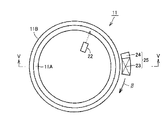
次に、図1を参照して、転走面焼入硬化工程が実施される。この転走面焼入硬化工程は、工程(S30)として実施される誘導加熱工程と、工程(S40)として実施される冷却工程とを含んでいる。工程(S30)では、図2および図3を参照して、誘導加熱部材としてのコイル21が、成形体(外輪)10において転動体が転走すべき面である転走面11A(環状領域)の一部に面するように配置される。ここで、コイル21は、2列の転走面のそれぞれに面するように2つ配置される。
Next, with reference to FIG. 1, a rolling surface quench hardening process is implemented. This rolling surface quench hardening process includes an induction heating process implemented as a process (S30) and a cooling process implemented as a process (S40). In step (S30), referring to FIG. 2 and FIG. 3,
次に、成形体11が中心軸周り、具体的には矢印αの向きに回転されるとともに、コイル21に対して電源(図示しない)から高周波電流が供給される。これにより、成形体11の転走面11Aを含む表層領域がA1点以上の温度に誘導加熱され、転走面11Aに沿った円環状の加熱領域11Cが形成される。このとき、転走面11Aの表面の温度は、放射温度計などの温度計22により測定され、管理される。
Next, the molded
次に、工程(S40)においては、工程(S30)において形成された加熱領域11Cを含む成形体11全体に対して、たとえば冷却液としての水が噴射されることにより、2列の加熱領域11C全体がMS点以下の温度に同時に冷却される。これにより、加熱領域11Cがマルテンサイトに変態し、硬化することにより転走面焼入層11Cとなる。以上の手順により、高周波焼入が実施され、転走面焼入硬化工程が完了する。
Next, in the step (S40), for example, water as a cooling liquid is sprayed onto the entire molded
次に、工程(S50)として嵌め合い面焼入硬化工程が実施される。この工程(S50)では、成形体11において嵌め合い面11Bを含む領域が焼入硬化される。具体的には、図4および図5を参照して、まず誘導加熱部材であるコイル23と、コイル23に隣接して配置される冷却部材としての冷却液噴射部24とを備えた移動焼入装置25が、嵌め合い面11Bの一部に面するように配置される。次に、移動焼入装置25が嵌め合い面11Bに沿って周方向(矢印βの方向)に移動する。このとき、コイル23に対して電源(図示しない)から高周波電流が供給される。これにより、成形体11の嵌め合い面11Bのうちコイル23に対向する領域がA1点以上の温度に誘導加熱される。一方、冷却液噴射部24からは、成形体11の嵌め合い面11Bに向けて冷却液が噴射される。その結果、嵌め合い面11Bのうちコイル23によりA1点以上の温度に誘導加熱された領域は、冷却液噴射部24から噴射される冷却液によりMS点以下の温度に冷却され、焼入硬化される。そして、このような焼入硬化処理が移動焼入装置25の移動に伴って順次実施されることにより、図5に示すように嵌め合い面焼入層11Dが形成される。
Next, a fitting surface hardening process is performed as a process (S50). In this step (S50), a region including the
次に、工程(S60)として焼戻工程が実施される。この工程(S60)では、工程(S30)〜(S50)において部分的に焼入硬化された成形体11が、たとえば炉内に装入され、A1点以下の温度に加熱されて所定の時間保持されることにより、焼戻処理が実施される。
Next, a tempering step is performed as a step (S60). In this step (S60), the molded
次に、工程(S70)として仕上工程が実施される。この工程(S70)では、たとえば転走面11Aに対して研磨加工などの仕上げ加工が実施される。以上のプロセスにより、外輪11が完成し、本実施の形態における外輪の製造は完了する。その結果、1000mm以上の内径を有し、高周波焼入によって転走面焼入層11Cが転走面11Aに沿って全周にわたって均質に形成された外輪11が完成する。
Next, a finishing step is performed as a step (S70). In this step (S70), for example, finishing such as polishing is performed on the rolling
さらに、工程(S80)として組立工程が実施される。この工程(S80)では、上述のように作製された外輪11と、上記外輪11と同様に作製された内輪12とが、別途準備されたころ13、保持器14などと組み合わされることにより、たとえば図6に示す複列円すいころ軸受1が組み立てられる。以上の手順により、本実施の形態における転がり軸受の製造方法は完了する。
Furthermore, an assembly process is performed as a process (S80). In this step (S80), the
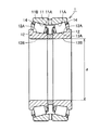
ここで、本実施の形態における転がり軸受である複列円すいころ軸受1は、図6を参照して、環状の外輪11と、外輪11の内側に配置された環状の2つの内輪12と、外輪11と内輪12との間に配置された複数の円すいころ13とを備えている。外輪11の内周面には2列の外輪転走面11Aが形成されており、2つの内輪12のそれぞれの外周面には1列の内輪転走面12Aが形成されている。そして、一方の内輪12の内輪転走面12Aが一方の外輪転走面11Aに対向し、他方の内輪12の内輪転走面12Aが他方の外輪転走面11Aに対向するように、1つの外輪11と2つの内輪12とは配置されている。さらに、複数の円すいころ13は、外輪転走面11Aのそれぞれに沿って、外輪転走面11Aと内輪転走面12Aとに接触し、保持器14によって保持されて周方向に所定のピッチで配置されることにより、2列の円環状の軌道上に転動自在に保持されている。以上の構成により、複列円すいころ軸受1の外輪11および内輪12は、互いに相対的に回転可能となっている。
Here, referring to FIG. 6, a double row tapered roller bearing 1 which is a rolling bearing in the present embodiment includes an annular
さらに、図6および図7を参照して、外輪11および内輪12は、1000mm以上の内径を有している。この外輪11および内輪12は、転動体であるころ13が転走すべき面である転走面11A,12Aを含むように転走面11A,12Aに沿って全周にわたって形成された転走面焼入層11C,12Cと、ハウジングや軸などの他の部材に嵌め合う嵌め合い面11B,12Bを含むように嵌め合い面11B,12Bに沿って形成された嵌め合い面焼入層11D,12Dと、転走面焼入層11C,12Cと嵌め合い面焼入層11D,12Dとの間に形成された非硬化領域11E,12Eとを備えている。そして、嵌め合い面焼入層11D,12Dの厚みは転走面焼入層11C,12Cの厚みよりも小さくなっている。
Further, referring to FIGS. 6 and 7,
本実施の形態における軌道輪(外輪11)の製造方法においては、転走面11Aとなるべき環状領域の一部に面するように配置された誘導加熱部材であるコイル21が周方向に沿って相対的に回転することにより、成形体11に加熱領域11Cが形成される。そのため、コイル21を小型化して焼入装置の製作コストを抑制することができる。また、本実施の形態においては加熱領域全体がMS点以下の温度に同時に冷却されるため、焼入硬化層を全周にわたって同時に形成することが可能となり、一部の領域に残留応力が集中することが抑制される。さらに、本実施の形態においては、上述のように移動焼入により嵌め合い面焼入層11Dが形成されるため、コイル23により加熱された領域が、加熱直後に冷却部材24により冷却されるため、先に形成された転走面焼入層11Cの硬度低下が抑制される。その結果、本実施の形態における軌道輪の製造方法によれば、焼入装置の製作コストを抑制しつつ、高周波焼入によって転走面焼入層11Cを全周にわたって均質に形成するとともに、転走面11Aの硬度の低下を抑制しつつ嵌め合い面焼入層11Dを形成することができる。また、本実施の形態における転がり軸受の製造方法によれば、高周波焼入によって転走面焼入層11Cが転走面11Aに沿って全周にわたって均質に形成されるとともに、転走面11Aの硬度の低下を抑制しつつ嵌め合い面焼入層11Dが嵌め合い面11Bに沿って形成された軌道輪を備える複列円すいころ軸受1を低コストで製造することができる。
In the manufacturing method of the raceway ring (outer ring 11) in the present embodiment, the
なお、上記工程(S20)として実施される焼きならし工程は、本発明の軌道輪の製造方法において必須の工程ではないが、これを実施することにより焼割れの発生を抑制しつつ、JIS規格SUP13、SCM445、SAE規格8660Hなどの鋼からなる成形体の硬度を調整することができる。 In addition, the normalizing process implemented as said process (S20) is not an essential process in the manufacturing method of the bearing ring of this invention, However, Implementing this suppresses generation | occurrence | production of a burning crack, JIS specification. The hardness of the molded body made of steel such as SUP13, SCM445, SAE standard 8660H can be adjusted.
この工程(S20)では、成形体11に気体とともに硬質の粒子が吹き付けられることにより、成形体11が冷却されつつショットブラスト処理が実施されてもよい。これにより、焼ならし処理の際の衝風冷却と同時にショットブラスト処理を実施することができるため、成形体11の表層部に生成したスケールが除去され、スケールの生成に起因した外輪11の特性低下やスケールの生成による熱伝導率の低下が抑制される。ここで、硬質の粒子(投射材)としては、たとえば鋼や鋳鉄などからなる金属製の粒子を採用することができる。
In this step (S <b> 20), the shot blasting process may be performed while the molded
また、上記工程(S30)では、成形体11は少なくとも1回転すればよいが、周方向における温度のばらつきを抑制し、より均質な焼入硬化を実現するためには、複数回回転することが好ましい。すなわち、誘導加熱部材としてのコイル21は、成形体11の転走面11Aの周方向に沿って相対的に2周以上回転することが好ましい。
In the step (S30), the molded
さらに、外輪11および内輪12においては、転走面焼入層11C,12Cと嵌め合い面焼入層11D,12Dとの間に非硬化領域11E,12Eが形成されるとともに、嵌め合い面焼入層11D,12Dの厚みが転走面焼入層11C,12Cの厚みよりも小さくなっている。これにより、外輪11および内輪12の転動疲労に対する耐久性が一層向上している。ここで、焼入層の厚み、すなわち誘導加熱により加熱される領域の厚みは、コイルに供給される電流の周波数、電源の出力などを調節することにより調整することができる。
Further, in the
(実施の形態2)
次に、本発明の他の実施の形態である実施の形態2について説明する。実施の形態2における外輪の製造方法は、基本的には実施の形態1の場合と同様に実施され、同様の効果を奏する。しかし、実施の形態2における外輪の製造方法は、工程(S30)におけるコイル21の配置において、実施の形態1の場合とは異なっている。
(Embodiment 2)
Next, Embodiment 2 which is another embodiment of the present invention will be described. The manufacturing method of the outer ring in the second embodiment is basically performed in the same manner as in the first embodiment, and has the same effect. However, the outer ring manufacturing method in the second embodiment is different from the first embodiment in the arrangement of the
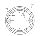
すなわち、図8を参照して、実施の形態2における工程(S30)では、誘導加熱部材として一対のコイル21が配置される。そして、成形体11が矢印αの向きに回転されるとともに、コイル21に対して電源(図示しない)から高周波電流が供給される。これにより、成形体11の転走面11Aを含む表層領域がA1点以上の温度に誘導加熱され、転走面11Aに沿った円環状の加熱領域11Cが形成される。
That is, referring to FIG. 8, in the step (S30) in the second embodiment, a pair of
このように、コイル21が成形体11の周方向に沿って複数個(本実施の形態では2個)配置されることにより、実施の形態2における転がり軸受の外輪11の製造方法は、周方向における温度のばらつきを抑制し、均質な焼入硬化を実現可能な軌道輪の製造方法となっている。また、周方向における温度のばらつきを一層抑制するためには、コイル21は成形体11の周方向において等間隔に配置されることが好ましい。
Thus, the manufacturing method of the outer ring |
(実施の形態3)
次に、本発明のさらに他の実施の形態である実施の形態3について説明する。実施の形態3における内輪の製造方法は、基本的には実施の形態1および2の場合と同様に実施され、同様の効果を奏する。しかし、実施の形態3における内輪の製造方法は、工程(S30)における温度計22の配置において、実施の形態1および2の場合とは異なっている。
(Embodiment 3)
Next,
すなわち、図9を参照して、実施の形態3における工程(S30)では、加熱領域である転走面11Aの複数箇所(ここでは4箇所)の温度が測定される。より具体的には、実施の形態3の工程(S30)では、成形体11の転走面11Aの周方向に沿って等間隔に複数の温度計22が配置され、周方向に等間隔な位置の温度が測定される。
That is, referring to FIG. 9, in step (S30) in the third embodiment, the temperatures at a plurality of locations (here, 4 locations) on rolling
これにより、転走面11Aの周方向において同時に複数箇所の温度が測定されるため、転走面11Aの周方向において均質な加熱が実現されていることを確認した上で成形体11を急冷し、焼入硬化処理を実施することができる。その結果、実施の形態3における転がり軸受の外輪の製造方法によれば、転走面11Aの周方向において一層均質な焼入硬化を実現することができる。
Thereby, since the temperature of several places is measured simultaneously in the circumferential direction of 11 A of rolling surfaces, after confirming that homogeneous heating is implement | achieved in the circumferential direction of 11 A of rolling surfaces, the molded
なお、上記実施の形態においてはコイル21を固定し、成形体11を回転させる場合について説明したが、成形体11を固定し、コイル21を成形体11の周方向に回転させてもよいし、コイル21および成形体11の両方を回転させることにより、コイル21を成形体11の周方向に沿って相対的に回転させてもよい。ただし、コイル21には、コイル21に電流を供給する配線などが必要であるため、上述のようにコイル21を固定することが合理的である場合が多い。
In addition, in the said embodiment, although the case where the
また、上記実施の形態においては、軌道輪の一例として複列円すいころ軸受の外輪が製造される場合について説明したが、本発明を適用可能な軌道輪はこれに限られず、たとえばラジアル型転がり軸受の軌道輪であってもよいし、スラスト型軸受の軌道輪であってもよい。ここで、工程(S20)において、たとえばラジアル型転がり軸受の内輪を加熱する場合、コイル21を成形体の外周側に形成された転走面に面するように配置すればよい。また、工程(S20)において、たとえばスラスト型転がり軸受の軌道輪を加熱する場合、コイル21を成形体の端面側に形成された転走面に面するように配置すればよい。
Further, in the above embodiment, the case where the outer ring of the double row tapered roller bearing is manufactured as an example of the bearing ring is described. However, the bearing ring to which the present invention is applicable is not limited to this, for example, a radial type rolling bearing. Or a thrust type bearing ring. Here, in the step (S20), for example, when heating the inner ring of the radial type rolling bearing, the
さらに、成形体11の周方向における誘導加熱部材としてのコイル21の長さは、効率よく均質な加熱を実現するように適切に決定することができるが、たとえば加熱すべき領域の長さの1/12程度、すなわち成形体(軌道輪)の中心軸に対する中心角が30°となる程度の長さとすることができる。
Furthermore, the length of the
また、周方向における温度のばらつきを抑制するためには、誘導加熱完了後、MS点以下の温度への冷却前に、成形体を加熱が停止された状態に保持する工程を設けることが好ましい。 Moreover, in order to suppress the variation in the temperature in the circumferential direction, it is preferable to provide a step of holding the molded body in a state where the heating is stopped after the induction heating is completed and before cooling to a temperature equal to or lower than the MS point. .
(実施の形態4)
次に、本発明の転がり軸受の製造方法により製造された転がり軸受が風力発電装置用軸受(風力発電装置用転がり軸受)として用いられる実施の形態4について説明する。
(Embodiment 4)
Next, Embodiment 4 in which the rolling bearing manufactured by the method for manufacturing a rolling bearing according to the present invention is used as a bearing for a wind turbine generator (a rolling bearing for a wind turbine generator) will be described.
図10を参照して、風力発電装置50は、旋回翼であるブレード52と、ブレード52の中心軸を含むように、一端においてブレード52に接続された主軸51と、主軸51の他端に接続された増速機54とを備えている。さらに、増速機54は、出力軸55を含んでおり、出力軸55は、発電機56に接続されている。主軸51は、風力発電装置用転がり軸受である主軸用軸受3により、軸まわりに回転自在に支持されている。また、主軸用軸受3は、主軸51の軸方向に複数個(図10では2個)並べて配置されており、それぞれハウジング53により保持されている。主軸用軸受3、ハウジング53、増速機54および発電機56は、機械室であるナセル59の内部に格納されている。そして、主軸51は一端においてナセル59から突出し、ブレード52に接続されている。
Referring to FIG. 10,
次に、風力発電装置50の動作について説明する。図10を参照して、風力を受けてブレード52が周方向に回転すると、ブレード52に接続された主軸51は、主軸用軸受3によりハウジング53に対して支持されつつ、軸まわりに回転する。主軸51の回転は、増速機54に伝達されて増速され、出力軸55の軸まわりの回転に変換される。そして、出力軸55の回転は、発電機56に伝達され、電磁誘導作用により起電力が発生して発電が達成される。
Next, the operation of the
次に、風力発電装置50の主軸51の支持構造について説明する。図11を参照して、風力発電装置用転がり軸受としての主軸用軸受3は、風力発電装置用転がり軸受の軌道輪としての環状の外輪31と、外輪31の内周側に配置された風力発電装置用転がり軸受の軌道輪としての環状の内輪32と、外輪31と内輪32との間に配置され、円環状の保持器34に保持された複数のころ33とを備えている。外輪31の内周面には外輪転走面31Aが形成されており、内輪32の外周面には内輪転走面32Aが形成されている。そして、内輪転走面32Aが、外輪転走面31Aに対向するように、外輪31と内輪32とは配置されている。さらに、複数のころ33は、2つの内輪転走面32Aのそれぞれに沿って、外輪転走面31Aと内輪転走面32Aとに、ころ接触面33Aにおいて接触し、かつ保持器34に保持されて周方向に所定のピッチで配置されることにより複列(2列)の円環状の軌道上に転動自在に保持されている。また、外輪31には、外輪31を径方向に貫通する貫通孔31Eが形成されている。この貫通孔31Eを通して、外輪31と内輪32との間の空間に潤滑剤を供給することができる。以上の構成により、主軸用軸受3の外輪31および内輪32は、互いに相対的に回転可能となっている。
Next, a support structure for the
一方、ブレード52に接続された主軸51は、主軸用軸受3の内輪32を貫通するとともに、外周面51Aにおいて内輪の内周面である嵌め合い面32Fに接触し、内輪32に対して嵌め込まれて固定されている。また、主軸用軸受3の外輪31は、ハウジング53に形成された貫通孔の内壁53Aに外周面である嵌め合い面31Fにおいて接触するように嵌め込まれ、ハウジング53に対して固定されている。以上の構成により、ブレード52に接続された主軸51は、内輪32と一体に、外輪31およびハウジング53に対して軸まわりに回転可能となっている。
On the other hand, the
さらに、内輪転走面32Aの幅方向両端には、外輪31に向けて突出する鍔部32Eが形成されている。これにより、ブレード52が風を受けることにより発生する主軸51の軸方向(アキシャル方向)の荷重が支持される。また、外輪転走面31Aは、球面形状を有している。そのため、外輪31と内輪32とは、ころ33の転走方向に垂直な断面において、当該球面の中心を中心として互いに角度をなすことができる。すなわち、主軸用軸受3は、複列自動調心ころ軸受である。その結果、ブレード52が風を受けることにより主軸51が撓んだ場合であっても、ハウジング53は、主軸用軸受3を介して主軸51を安定して回転自在に保持することができる。
Further,
そして、実施の形態4における風力発電装置用転がり軸受の軌道輪としての外輪31および内輪32は、上述の実施の形態1における外輪11および内輪12と同様の製造方法により製造され、同様の構造を有している。すなわち、外輪31および内輪32は、外輪11および内輪12と同様に、1000mm以上の内径を有している。また、外輪31および内輪32は、転走面31A,32Aを含むように転走面31A,32Aに沿って全周にわたって形成された転走面焼入層31G,32Gと、他の部材であるハウジング53に嵌め合う嵌め合い面31F、あるいは他の部材である主軸51に嵌め合う嵌め合い面32Fを含むように嵌め合い面31F,32Fに沿って形成された嵌め合い面焼入層31H,32Hと、転走面焼入層31G,32Gと嵌め合い面焼入層31H,32Hとの間に形成された非硬化領域31I,32Iとを備えている。そして、嵌め合い面焼入層31H,32Hの厚みは転走面焼入層31G,32Gの厚みよりも小さくなっている。その結果、上記外輪31および内輪32は、転走面焼入層31G,32Gが転走面31A,32Aに沿って形成され、耐久性が向上した大型の転がり軸受の軌道輪となっている。また、上記外輪31および内輪32を備えた主軸用軸受3(自動調心ころ軸受)は、耐久性に優れた大型の転がり軸受となっている。
And the outer ring |
なお、本発明の軌道輪および転がり軸受は、大型の転がり軸受の軌道輪および当該軌道輪を備えた転がり軸受に好適である。上記実施の形態4においては、大型の転がり軸受の一例として風力発電装置用軸受について説明したが、他の大型の転がり軸受への適用も可能である。具体的には、たとえばCTスキャナのX線照射部が設置された回転架台を、当該回転架台に対向するように配置される固定架台に対して回転自在に支持するCTスキャナ用転がり軸受に、本発明の軌道輪および転がり軸受を好適に適用することができる。また、本発明の軌道輪および転がり軸受は、たとえば深溝玉軸受、アンギュラ玉軸受、円筒ころ軸受、円すいころ軸受、自動調心ころ軸受、スラスト玉軸受など、任意の形態の軌道輪および転がり軸受に適用可能である。また、上記実施の形態においては、内輪および外輪の両方が本発明の軌道輪の製造方法により製造された軌道輪である場合について説明したが、本発明の転がり軸受はこれに限られず、内輪および外輪の一方が本発明の軌道輪の製造方法により製造されたものであってもよい。 The bearing ring and rolling bearing of the present invention are suitable for a bearing ring of a large-sized rolling bearing and a rolling bearing provided with the bearing ring. In the said Embodiment 4, although the bearing for wind power generators was demonstrated as an example of a large sized rolling bearing, the application to another large sized rolling bearing is also possible. More specifically, for example, the present invention is applied to a rolling bearing for a CT scanner that rotatably supports a rotating mount on which an X-ray irradiation unit of a CT scanner is installed with respect to a fixed mount that is arranged so as to face the rotating mount. The bearing ring and the rolling bearing of the invention can be preferably applied. Further, the bearing ring and rolling bearing of the present invention can be applied to any form of bearing ring and rolling bearing such as a deep groove ball bearing, an angular ball bearing, a cylindrical roller bearing, a tapered roller bearing, a self-aligning roller bearing, and a thrust ball bearing. Applicable. Further, in the above embodiment, the case where both the inner ring and the outer ring are race rings manufactured by the method for manufacturing a race ring of the present invention has been described. However, the rolling bearing of the present invention is not limited to this, and the inner ring and One of the outer rings may be manufactured by the track ring manufacturing method of the present invention.
今回開示された実施の形態はすべての点で例示であって、制限的なものではないと考えられるべきである。本発明の範囲は上記した説明ではなくて特許請求の範囲によって示され、特許請求の範囲と均等の意味、および範囲内でのすべての変更が含まれることが意図される。 The embodiment disclosed this time is to be considered as illustrative in all points and not restrictive. The scope of the present invention is defined by the terms of the claims, rather than the description above, and is intended to include any modifications within the scope and meaning equivalent to the terms of the claims.
本発明の軌道輪の製造方法および転がり軸受の製造方法は、高周波焼入によって焼入硬化層を転走面に沿って全周にわたって均質に形成することが求められる軌道輪の製造方法、および転がり軸受の製造方法に、特に有利に適用され得る。 The method for manufacturing a bearing ring and the method for manufacturing a rolling bearing according to the present invention includes a method for manufacturing a bearing ring and a rolling method in which a hardened hardened layer is required to be uniformly formed along the rolling surface by induction hardening. The present invention can be applied particularly advantageously to a method for manufacturing a bearing.
1 複列円すいころ軸受、3 主軸用軸受、11 外輪(成形体)、11A 外輪転走面、11B,12B 嵌め合い面、11C,12C 転走面焼入層(加熱領域)、11D,12D 嵌め合い面焼入層、11E,12E 非硬化領域、12 内輪、12A 内輪転走面、13 ころ、14 保持器、21,23 コイル、22 温度計、24 冷却液噴射部、25 移動焼入装置、31 外輪、31A 外輪転走面、31E 貫通孔、31F,32F 嵌め合い面、31G,32G 転走面焼入層、31H,32H 嵌め合い面焼入層、31I,32I 非硬化領域、32 内輪、32A 内輪転走面、32E 鍔部、33 ころ、33A ころ接触面、34 保持器、50 風力発電装置、51 主軸、51A 外周面、52 ブレード、53 ハウジング、53A 内壁、54 増速機、55 出力軸、56 発電機、59 ナセル。
DESCRIPTION OF SYMBOLS 1 Double row tapered roller bearing, 3 Main shaft bearing, 11 Outer ring (molded body), 11A Outer ring rolling surface, 11B, 12B fitting surface, 11C, 12C Rolling surface hardened layer (heating region), 11D, 12D fitting Mating surface hardened layer, 11E, 12E non-hardened region, 12 inner ring, 12A inner ring rolling surface, 13 rollers, 14 cage, 21, 23 coil, 22 thermometer, 24 coolant injection unit, 25 moving quenching device, 31 outer ring, 31A outer ring rolling surface, 31E through hole, 31F, 32F mating surface, 31G, 32G rolling surface hardened layer, 31H, 32H mating surface hardened layer, 31I, 32I non-hardened region, 32 inner ring, 32A inner ring rolling surface, 32E buttocks, 33 rollers, 33A roller contact surface, 34 cage, 50 wind power generator, 51 main shaft, 51A outer peripheral surface, 52 blade, 53 housing, 3A
Claims (12)
鋼から構成される成形体を準備する工程と、
前記成形体において前記軌道輪の転走面となるべき環状領域の一部に面するように配置され、前記成形体を誘導加熱する誘導加熱部材を、前記環状領域の周方向に沿って相対的に回転させることにより、前記成形体にA1点以上の温度に加熱された環状の加熱領域を形成する工程と、
前記加熱領域全体をMS点以下の温度に同時に冷却することにより、転走面焼入層を前記環状領域に沿って全周にわたって形成する工程と、
前記成形体において前記軌道輪の嵌め合い面となるべき領域の一部に面するように配置され、前記成形体を誘導加熱する他の誘導加熱部材を、前記嵌め合い面となるべき領域の周方向に沿って相対的に移動させるとともに、前記他の誘導加熱部材を追動する冷却部材により、前記他の誘導加熱部材によって加熱された領域を冷却することで嵌め合い面焼入層を形成する工程とを備えた、軌道輪の製造方法。 A method of manufacturing a bearing ring for a rolling bearing,
Preparing a formed body made of steel;
An induction heating member that is arranged so as to face a part of an annular region that is to be a rolling surface of the raceway in the molded body and that is relatively heated along a circumferential direction of the annular region. To form an annular heating region heated to a temperature of A 1 point or more in the molded body,
By simultaneously cooling the entire heating region to a temperature below M S point, forming a rolling surface hardening layer over the entire circumference along the annular region,
Another induction heating member that is arranged so as to face a part of the region to be the fitting surface of the raceway in the molded body and that induction heats the molded body is arranged around the region to be the fitting surface. The fitting surface hardened layer is formed by cooling the region heated by the other induction heating member by the cooling member that moves relative to the direction and moves the other induction heating member. A method of manufacturing a bearing ring, comprising: a process.
前記転走面焼入層を形成する工程では、複列の前記加熱領域が同時にMS点以下の温度に冷却される、請求項1〜4のいずれか1項に記載の軌道輪の製造方法。 The raceway includes a double row rolling surface;
The rolling surface in the step of forming the hardening layer, the heating region of the double row is cooled M S point below the temperature at the same time, the manufacturing method of the bearing ring according to any one of claims 1-4 .
転動体を準備する工程と、
前記軌道輪と前記転動体とを組み合わせて転がり軸受を組み立てる工程とを備え、
前記軌道輪は、請求項1〜10のいずれか1項に記載の軌道輪の製造方法により製造される、転がり軸受の製造方法。 A process of preparing a bearing ring;
Preparing a rolling element;
A step of assembling a rolling bearing by combining the raceway and the rolling element,
The bearing ring is manufactured by the manufacturing method of the bearing ring according to any one of claims 1-10, a manufacturing method of the rolling bearing.
Priority Applications (10)
| Application Number | Priority Date | Filing Date | Title |
|---|---|---|---|
| JP2009273388A JP5455031B2 (en) | 2009-12-01 | 2009-12-01 | Manufacturing method of bearing ring and manufacturing method of rolling bearing |
| US13/386,314 US20120121420A1 (en) | 2009-07-22 | 2010-07-21 | Method for heat-treating a ring-shaped member, method for producing a ring-shaped member, ring-shaped member, bearing ring, rolling bearing, and method for producing a bearing ring |
| EP15176055.0A EP2987873A3 (en) | 2009-07-22 | 2010-07-21 | Method for heat-treating a ring-shaped member, method for producing a ring-shaped member, ring-shaped member, bearing ring, rolling bearing, and method for producing a bearing ring |
| PCT/JP2010/062248 WO2011010664A1 (en) | 2009-07-22 | 2010-07-21 | Method for heat-treating a ring-shaped member, method for producing a ring-shaped member, ring-shaped member, bearing ring, rolling bearing, and method for producing a bearing ring |
| ES10802284.9T ES2569487T3 (en) | 2009-07-22 | 2010-07-21 | Heat treatment procedure of a ring-shaped member, procedure for producing a ring-shaped member, ring-shaped member, support crown, roller bearing, and procedure for producing a support crown |
| CN2010800312588A CN102471820A (en) | 2009-07-22 | 2010-07-21 | Method for heat-treating a ring-shaped member, method for producing a ring-shaped member, ring-shaped member, bearing ring, rolling bearing, and method for producing a bearing ring |
| EP10802284.9A EP2458023B1 (en) | 2009-07-22 | 2010-07-21 | Method for heat-treating a ring-shaped member, method for producing a ring-shaped member, ring-shaped member, bearing ring, rolling bearing, and method for producing a bearing ring |
| DK10802284.9T DK2458023T3 (en) | 2009-07-22 | 2010-07-21 | A method of heat-treating a ring shaped article, method of producing a ring-shaped article, the ring shaped article, bearing ring, roller bearing and the method of manufacturing a bearing ring |
| CN201510009308.7A CN104694729A (en) | 2009-07-22 | 2010-07-21 | Method for heat-treating a ring-shaped member, method for producing a ring-shaped member, ring-shaped member, bearing ring, rolling bearing, and method for producing a bearing ring |
| US15/016,906 US20160153496A1 (en) | 2009-07-22 | 2016-02-05 | Method for heat-treating a ring-shaped member, method for producing a ring-shaped member, ring-shaped member, bearing ring, rolling bearing, and method for producing a bearing ring |
Applications Claiming Priority (1)
| Application Number | Priority Date | Filing Date | Title |
|---|---|---|---|
| JP2009273388A JP5455031B2 (en) | 2009-12-01 | 2009-12-01 | Manufacturing method of bearing ring and manufacturing method of rolling bearing |
Publications (3)
| Publication Number | Publication Date |
|---|---|
| JP2011117018A JP2011117018A (en) | 2011-06-16 |
| JP2011117018A5 JP2011117018A5 (en) | 2013-01-17 |
| JP5455031B2 true JP5455031B2 (en) | 2014-03-26 |
Family
ID=44282675
Family Applications (1)
| Application Number | Title | Priority Date | Filing Date |
|---|---|---|---|
| JP2009273388A Expired - Fee Related JP5455031B2 (en) | 2009-07-22 | 2009-12-01 | Manufacturing method of bearing ring and manufacturing method of rolling bearing |
Country Status (1)
| Country | Link |
|---|---|
| JP (1) | JP5455031B2 (en) |
Families Citing this family (4)
| Publication number | Priority date | Publication date | Assignee | Title |
|---|---|---|---|---|
| JP2014025097A (en) * | 2012-07-25 | 2014-02-06 | Ntn Corp | Method for manufacturing bearing ring, bearing ring and rolling bearing |
| JP6023493B2 (en) * | 2012-07-25 | 2016-11-09 | Ntn株式会社 | Method of manufacturing bearing ring, bearing ring and rolling bearing |
| CN114055096B (en) * | 2021-12-08 | 2023-05-16 | 中国铁建重工集团股份有限公司 | Machining method for flange of joint surface of main bearing ring of oversized heading machine |
| CN114277228A (en) * | 2021-12-29 | 2022-04-05 | 远景能源有限公司 | Large self-aligning roller bearing and manufacturing method thereof |
-
2009
- 2009-12-01 JP JP2009273388A patent/JP5455031B2/en not_active Expired - Fee Related
Also Published As
| Publication number | Publication date |
|---|---|
| JP2011117018A (en) | 2011-06-16 |
Similar Documents
| Publication | Publication Date | Title |
|---|---|---|
| WO2011010664A1 (en) | Method for heat-treating a ring-shaped member, method for producing a ring-shaped member, ring-shaped member, bearing ring, rolling bearing, and method for producing a bearing ring | |
| WO2012098988A1 (en) | Method for manufacturing bearing ring, bearing ring, and rolling bearing | |
| JP5775422B2 (en) | Heat treatment method for ring-shaped member and method for manufacturing ring-shaped member | |
| JP5773348B2 (en) | Method of manufacturing bearing ring, bearing ring and rolling bearing | |
| JP5665564B2 (en) | Manufacturing method of bearing ring | |
| JP5455031B2 (en) | Manufacturing method of bearing ring and manufacturing method of rolling bearing | |
| JP2015180783A (en) | Bearing ring and method of producing rolling bearing | |
| JP5557235B2 (en) | Heat treatment method for ring-shaped member, method for manufacturing ring-shaped member | |
| JP5773349B2 (en) | Method of manufacturing bearing ring and rolling bearing | |
| JP6023493B2 (en) | Method of manufacturing bearing ring, bearing ring and rolling bearing | |
| JP5534403B2 (en) | Bearing rings and rolling bearings | |
| WO2017203915A1 (en) | Heat treatment method for ring-shaped member, manufacturing method for ring-shaped member, bearing ring of roller bearing, and roller bearing | |
| WO2017073325A1 (en) | Method for manufacturing bearing ring, and multi-row tapered roller bearing and manufacturing method therefor | |
| JP2014095154A (en) | Heat treatment method for ring-shaped member, method for producing ring-shaped member, ring-shaped member, bearing ring of rolling bearing, and rolling bearing | |
| JP2015193936A (en) | Bearing ring and method of producing rolling bearing | |
| JP2015187310A (en) | Bearing ring production method, bearing ring, and rolling bearing | |
| JP6072145B2 (en) | Manufacturing method of bearing ring | |
| JP6178365B2 (en) | Manufacturing method of bearing ring, cylindrical roller bearing and tapered roller bearing | |
| JP2015212404A (en) | Manufacturing method of bearing ring, bearing ring and rolling shaft bearing | |
| JP2014025097A (en) | Method for manufacturing bearing ring, bearing ring and rolling bearing | |
| WO2017199872A1 (en) | Method for heat-treating ring-shaped member, method for manufacturing ring-shaped member, raceway of rolling bearing, and rolling bearing | |
| JP5721449B2 (en) | Bearing rings and rolling bearings | |
| JP5665565B2 (en) | Manufacturing method of bearing ring | |
| JP2015187311A (en) | Bearing ring production method, bearing ring, and rolling bearing | |
| JP2017082300A (en) | Manufacturing method of bearing ring and double row tapered roller bearing |
Legal Events
| Date | Code | Title | Description |
|---|---|---|---|
| A521 | Request for written amendment filed |
Free format text: JAPANESE INTERMEDIATE CODE: A523 Effective date: 20121128 |
|
| A621 | Written request for application examination |
Free format text: JAPANESE INTERMEDIATE CODE: A621 Effective date: 20121128 |
|
| TRDD | Decision of grant or rejection written | ||
| A01 | Written decision to grant a patent or to grant a registration (utility model) |
Free format text: JAPANESE INTERMEDIATE CODE: A01 Effective date: 20131210 |
|
| A61 | First payment of annual fees (during grant procedure) |
Free format text: JAPANESE INTERMEDIATE CODE: A61 Effective date: 20131226 |
|
| R150 | Certificate of patent or registration of utility model |
Free format text: JAPANESE INTERMEDIATE CODE: R150 Ref document number: 5455031 Country of ref document: JP Free format text: JAPANESE INTERMEDIATE CODE: R150 |
|
| R250 | Receipt of annual fees |
Free format text: JAPANESE INTERMEDIATE CODE: R250 |
|
| R250 | Receipt of annual fees |
Free format text: JAPANESE INTERMEDIATE CODE: R250 |
|
| R250 | Receipt of annual fees |
Free format text: JAPANESE INTERMEDIATE CODE: R250 |
|
| R250 | Receipt of annual fees |
Free format text: JAPANESE INTERMEDIATE CODE: R250 |
|
| R250 | Receipt of annual fees |
Free format text: JAPANESE INTERMEDIATE CODE: R250 |
|
| LAPS | Cancellation because of no payment of annual fees |