JP5775422B2 - Heat treatment method for ring-shaped member and method for manufacturing ring-shaped member - Google Patents
Heat treatment method for ring-shaped member and method for manufacturing ring-shaped member Download PDFInfo
- Publication number
- JP5775422B2 JP5775422B2 JP2011237495A JP2011237495A JP5775422B2 JP 5775422 B2 JP5775422 B2 JP 5775422B2 JP 2011237495 A JP2011237495 A JP 2011237495A JP 2011237495 A JP2011237495 A JP 2011237495A JP 5775422 B2 JP5775422 B2 JP 5775422B2
- Authority
- JP
- Japan
- Prior art keywords
- ring
- shaped member
- mass
- less
- heat treatment
- Prior art date
- Legal status (The legal status is an assumption and is not a legal conclusion. Google has not performed a legal analysis and makes no representation as to the accuracy of the status listed.)
- Expired - Fee Related
Links
- 238000010438 heat treatment Methods 0.000 title claims description 89
- 238000000034 method Methods 0.000 title claims description 62
- 238000004519 manufacturing process Methods 0.000 title claims description 43
- 238000005096 rolling process Methods 0.000 claims description 66
- 238000010791 quenching Methods 0.000 claims description 44
- 229910000831 Steel Inorganic materials 0.000 claims description 41
- 239000010959 steel Substances 0.000 claims description 41
- 230000000171 quenching effect Effects 0.000 claims description 31
- 230000006698 induction Effects 0.000 claims description 18
- PXHVJJICTQNCMI-UHFFFAOYSA-N Nickel Chemical compound [Ni] PXHVJJICTQNCMI-UHFFFAOYSA-N 0.000 claims description 16
- 230000002093 peripheral effect Effects 0.000 claims description 16
- OKTJSMMVPCPJKN-UHFFFAOYSA-N Carbon Chemical compound [C] OKTJSMMVPCPJKN-UHFFFAOYSA-N 0.000 claims description 14
- 229910052799 carbon Inorganic materials 0.000 claims description 14
- VYZAMTAEIAYCRO-UHFFFAOYSA-N Chromium Chemical compound [Cr] VYZAMTAEIAYCRO-UHFFFAOYSA-N 0.000 claims description 10
- XEEYBQQBJWHFJM-UHFFFAOYSA-N Iron Chemical compound [Fe] XEEYBQQBJWHFJM-UHFFFAOYSA-N 0.000 claims description 10
- ZOKXTWBITQBERF-UHFFFAOYSA-N Molybdenum Chemical compound [Mo] ZOKXTWBITQBERF-UHFFFAOYSA-N 0.000 claims description 10
- 229910052804 chromium Inorganic materials 0.000 claims description 10
- 239000011651 chromium Substances 0.000 claims description 10
- 229910052750 molybdenum Inorganic materials 0.000 claims description 10
- 239000011733 molybdenum Substances 0.000 claims description 10
- 229910052710 silicon Inorganic materials 0.000 claims description 10
- 239000010703 silicon Substances 0.000 claims description 10
- 229910052759 nickel Inorganic materials 0.000 claims description 8
- 229910001566 austenite Inorganic materials 0.000 claims description 7
- 238000001816 cooling Methods 0.000 claims description 6
- 239000012535 impurity Substances 0.000 claims description 5
- 229910052742 iron Inorganic materials 0.000 claims description 5
- WPBNNNQJVZRUHP-UHFFFAOYSA-L manganese(2+);methyl n-[[2-(methoxycarbonylcarbamothioylamino)phenyl]carbamothioyl]carbamate;n-[2-(sulfidocarbothioylamino)ethyl]carbamodithioate Chemical compound [Mn+2].[S-]C(=S)NCCNC([S-])=S.COC(=O)NC(=S)NC1=CC=CC=C1NC(=S)NC(=O)OC WPBNNNQJVZRUHP-UHFFFAOYSA-L 0.000 claims description 5
- 230000001186 cumulative effect Effects 0.000 claims description 3
- 238000003672 processing method Methods 0.000 claims 2
- 230000008569 process Effects 0.000 description 26
- 239000000463 material Substances 0.000 description 11
- XUIMIQQOPSSXEZ-UHFFFAOYSA-N Silicon Chemical compound [Si] XUIMIQQOPSSXEZ-UHFFFAOYSA-N 0.000 description 8
- 230000007423 decrease Effects 0.000 description 6
- PWHULOQIROXLJO-UHFFFAOYSA-N Manganese Chemical compound [Mn] PWHULOQIROXLJO-UHFFFAOYSA-N 0.000 description 5
- 230000000694 effects Effects 0.000 description 5
- 229910052748 manganese Inorganic materials 0.000 description 5
- 239000011572 manganese Substances 0.000 description 5
- 238000010586 diagram Methods 0.000 description 4
- 230000006872 improvement Effects 0.000 description 4
- 238000010248 power generation Methods 0.000 description 4
- 239000002344 surface layer Substances 0.000 description 4
- 238000005259 measurement Methods 0.000 description 3
- 238000005496 tempering Methods 0.000 description 3
- 239000013078 crystal Substances 0.000 description 2
- 239000003302 ferromagnetic material Substances 0.000 description 2
- 230000020169 heat generation Effects 0.000 description 2
- 229910000734 martensite Inorganic materials 0.000 description 2
- 239000002907 paramagnetic material Substances 0.000 description 2
- 239000006104 solid solution Substances 0.000 description 2
- 238000005482 strain hardening Methods 0.000 description 2
- 230000009466 transformation Effects 0.000 description 2
- 230000009471 action Effects 0.000 description 1
- 229910001563 bainite Inorganic materials 0.000 description 1
- 230000008901 benefit Effects 0.000 description 1
- 230000015572 biosynthetic process Effects 0.000 description 1
- 239000002826 coolant Substances 0.000 description 1
- 239000000110 cooling liquid Substances 0.000 description 1
- 125000004122 cyclic group Chemical group 0.000 description 1
- 230000005674 electromagnetic induction Effects 0.000 description 1
- 238000007730 finishing process Methods 0.000 description 1
- 238000005242 forging Methods 0.000 description 1
- 239000010410 layer Substances 0.000 description 1
- 239000000314 lubricant Substances 0.000 description 1
- 239000000203 mixture Substances 0.000 description 1
- 238000012986 modification Methods 0.000 description 1
- 230000004048 modification Effects 0.000 description 1
- 239000003921 oil Substances 0.000 description 1
- 229910001562 pearlite Inorganic materials 0.000 description 1
- 238000007517 polishing process Methods 0.000 description 1
- 238000002360 preparation method Methods 0.000 description 1
- 230000000717 retained effect Effects 0.000 description 1
- 238000004781 supercooling Methods 0.000 description 1
- XLYOFNOQVPJJNP-UHFFFAOYSA-N water Substances O XLYOFNOQVPJJNP-UHFFFAOYSA-N 0.000 description 1
- 229910000859 α-Fe Inorganic materials 0.000 description 1
Images


Classifications
-
- C—CHEMISTRY; METALLURGY
- C21—METALLURGY OF IRON
- C21D—MODIFYING THE PHYSICAL STRUCTURE OF FERROUS METALS; GENERAL DEVICES FOR HEAT TREATMENT OF FERROUS OR NON-FERROUS METALS OR ALLOYS; MAKING METAL MALLEABLE, e.g. BY DECARBURISATION OR TEMPERING
- C21D9/00—Heat treatment, e.g. annealing, hardening, quenching or tempering, adapted for particular articles; Furnaces therefor
- C21D9/40—Heat treatment, e.g. annealing, hardening, quenching or tempering, adapted for particular articles; Furnaces therefor for rings; for bearing races
-
- C—CHEMISTRY; METALLURGY
- C21—METALLURGY OF IRON
- C21D—MODIFYING THE PHYSICAL STRUCTURE OF FERROUS METALS; GENERAL DEVICES FOR HEAT TREATMENT OF FERROUS OR NON-FERROUS METALS OR ALLOYS; MAKING METAL MALLEABLE, e.g. BY DECARBURISATION OR TEMPERING
- C21D1/00—General methods or devices for heat treatment, e.g. annealing, hardening, quenching or tempering
- C21D1/06—Surface hardening
- C21D1/09—Surface hardening by direct application of electrical or wave energy; by particle radiation
- C21D1/10—Surface hardening by direct application of electrical or wave energy; by particle radiation by electric induction
-
- C—CHEMISTRY; METALLURGY
- C21—METALLURGY OF IRON
- C21D—MODIFYING THE PHYSICAL STRUCTURE OF FERROUS METALS; GENERAL DEVICES FOR HEAT TREATMENT OF FERROUS OR NON-FERROUS METALS OR ALLOYS; MAKING METAL MALLEABLE, e.g. BY DECARBURISATION OR TEMPERING
- C21D1/00—General methods or devices for heat treatment, e.g. annealing, hardening, quenching or tempering
- C21D1/34—Methods of heating
- C21D1/42—Induction heating
-
- C—CHEMISTRY; METALLURGY
- C22—METALLURGY; FERROUS OR NON-FERROUS ALLOYS; TREATMENT OF ALLOYS OR NON-FERROUS METALS
- C22C—ALLOYS
- C22C38/00—Ferrous alloys, e.g. steel alloys
-
- C—CHEMISTRY; METALLURGY
- C22—METALLURGY; FERROUS OR NON-FERROUS ALLOYS; TREATMENT OF ALLOYS OR NON-FERROUS METALS
- C22C—ALLOYS
- C22C38/00—Ferrous alloys, e.g. steel alloys
- C22C38/02—Ferrous alloys, e.g. steel alloys containing silicon
-
- C—CHEMISTRY; METALLURGY
- C22—METALLURGY; FERROUS OR NON-FERROUS ALLOYS; TREATMENT OF ALLOYS OR NON-FERROUS METALS
- C22C—ALLOYS
- C22C38/00—Ferrous alloys, e.g. steel alloys
- C22C38/04—Ferrous alloys, e.g. steel alloys containing manganese
-
- C—CHEMISTRY; METALLURGY
- C22—METALLURGY; FERROUS OR NON-FERROUS ALLOYS; TREATMENT OF ALLOYS OR NON-FERROUS METALS
- C22C—ALLOYS
- C22C38/00—Ferrous alloys, e.g. steel alloys
- C22C38/18—Ferrous alloys, e.g. steel alloys containing chromium
- C22C38/22—Ferrous alloys, e.g. steel alloys containing chromium with molybdenum or tungsten
-
- C—CHEMISTRY; METALLURGY
- C22—METALLURGY; FERROUS OR NON-FERROUS ALLOYS; TREATMENT OF ALLOYS OR NON-FERROUS METALS
- C22C—ALLOYS
- C22C38/00—Ferrous alloys, e.g. steel alloys
- C22C38/18—Ferrous alloys, e.g. steel alloys containing chromium
- C22C38/40—Ferrous alloys, e.g. steel alloys containing chromium with nickel
- C22C38/44—Ferrous alloys, e.g. steel alloys containing chromium with nickel with molybdenum or tungsten
-
- F—MECHANICAL ENGINEERING; LIGHTING; HEATING; WEAPONS; BLASTING
- F16—ENGINEERING ELEMENTS AND UNITS; GENERAL MEASURES FOR PRODUCING AND MAINTAINING EFFECTIVE FUNCTIONING OF MACHINES OR INSTALLATIONS; THERMAL INSULATION IN GENERAL
- F16C—SHAFTS; FLEXIBLE SHAFTS; ELEMENTS OR CRANKSHAFT MECHANISMS; ROTARY BODIES OTHER THAN GEARING ELEMENTS; BEARINGS
- F16C33/00—Parts of bearings; Special methods for making bearings or parts thereof
- F16C33/30—Parts of ball or roller bearings
- F16C33/58—Raceways; Race rings
- F16C33/64—Special methods of manufacture
-
- F—MECHANICAL ENGINEERING; LIGHTING; HEATING; WEAPONS; BLASTING
- F16—ENGINEERING ELEMENTS AND UNITS; GENERAL MEASURES FOR PRODUCING AND MAINTAINING EFFECTIVE FUNCTIONING OF MACHINES OR INSTALLATIONS; THERMAL INSULATION IN GENERAL
- F16C—SHAFTS; FLEXIBLE SHAFTS; ELEMENTS OR CRANKSHAFT MECHANISMS; ROTARY BODIES OTHER THAN GEARING ELEMENTS; BEARINGS
- F16C2204/00—Metallic materials; Alloys
- F16C2204/60—Ferrous alloys, e.g. steel alloys
- F16C2204/64—Medium carbon steel, i.e. carbon content from 0.4 to 0,8 wt%
-
- F—MECHANICAL ENGINEERING; LIGHTING; HEATING; WEAPONS; BLASTING
- F16—ENGINEERING ELEMENTS AND UNITS; GENERAL MEASURES FOR PRODUCING AND MAINTAINING EFFECTIVE FUNCTIONING OF MACHINES OR INSTALLATIONS; THERMAL INSULATION IN GENERAL
- F16C—SHAFTS; FLEXIBLE SHAFTS; ELEMENTS OR CRANKSHAFT MECHANISMS; ROTARY BODIES OTHER THAN GEARING ELEMENTS; BEARINGS
- F16C2300/00—Application independent of particular apparatuses
- F16C2300/10—Application independent of particular apparatuses related to size
- F16C2300/14—Large applications, e.g. bearings having an inner diameter exceeding 500 mm
-
- F—MECHANICAL ENGINEERING; LIGHTING; HEATING; WEAPONS; BLASTING
- F16—ENGINEERING ELEMENTS AND UNITS; GENERAL MEASURES FOR PRODUCING AND MAINTAINING EFFECTIVE FUNCTIONING OF MACHINES OR INSTALLATIONS; THERMAL INSULATION IN GENERAL
- F16C—SHAFTS; FLEXIBLE SHAFTS; ELEMENTS OR CRANKSHAFT MECHANISMS; ROTARY BODIES OTHER THAN GEARING ELEMENTS; BEARINGS
- F16C2360/00—Engines or pumps
- F16C2360/31—Wind motors
-
- Y—GENERAL TAGGING OF NEW TECHNOLOGICAL DEVELOPMENTS; GENERAL TAGGING OF CROSS-SECTIONAL TECHNOLOGIES SPANNING OVER SEVERAL SECTIONS OF THE IPC; TECHNICAL SUBJECTS COVERED BY FORMER USPC CROSS-REFERENCE ART COLLECTIONS [XRACs] AND DIGESTS
- Y02—TECHNOLOGIES OR APPLICATIONS FOR MITIGATION OR ADAPTATION AGAINST CLIMATE CHANGE
- Y02P—CLIMATE CHANGE MITIGATION TECHNOLOGIES IN THE PRODUCTION OR PROCESSING OF GOODS
- Y02P10/00—Technologies related to metal processing
- Y02P10/25—Process efficiency
Landscapes
- Chemical & Material Sciences (AREA)
- Engineering & Computer Science (AREA)
- Mechanical Engineering (AREA)
- Materials Engineering (AREA)
- Metallurgy (AREA)
- Organic Chemistry (AREA)
- Crystallography & Structural Chemistry (AREA)
- Thermal Sciences (AREA)
- Physics & Mathematics (AREA)
- General Engineering & Computer Science (AREA)
- Manufacturing & Machinery (AREA)
- Heat Treatment Of Articles (AREA)
- Rolling Contact Bearings (AREA)
Description
本発明はリング状部材の熱処理方法およびリング状部材の製造方法に関し、より特定的には、焼入装置の製作コストを抑制することが可能なリング状部材の熱処理方法およびリング状部材の製造方法に関するものである。 The present invention relates to a ring-shaped member heat treatment method and a ring-shaped member manufacturing method, and more specifically, a ring-shaped member heat treatment method and a ring-shaped member manufacturing method capable of suppressing the manufacturing cost of a quenching apparatus. It is about.
転がり軸受の軌道輪などの鋼からなるリング状部材に対する焼入硬化処理として、高周波焼入が採用される場合がある。この高周波焼入は、リング状部材を炉内で加熱した後、油などの冷却液中に浸漬する一般的な焼入硬化処理に比べて、設備を簡略化できるとともに、短時間での熱処理が可能となるなどの利点を有している。 Induction hardening may be employed as a quench hardening treatment for a ring-shaped member made of steel such as a bearing ring of a rolling bearing. This induction hardening can simplify the equipment and heat treatment in a short time compared to the general quench hardening process in which a ring-shaped member is heated in a furnace and then immersed in a coolant such as oil. It has the advantage that it becomes possible.
しかし、高周波焼入において、リング状部材の周方向に沿った焼入硬化すべき環状の領域を同時に加熱するためには、当該領域に対向するように、リング状部材を誘導加熱するためのコイルなどの誘導加熱部材を配置する必要がある(たとえば、特許文献1参照)。そのため、大型のリング状部材を焼入硬化する場合、それに応じた大型のコイルや当該コイルに対応する大容量の電源が必要となり、焼入装置の製作コストが高くなるという問題がある。 However, in induction hardening, in order to simultaneously heat an annular region to be hardened by hardening in the circumferential direction of the ring-shaped member, a coil for inductively heating the ring-shaped member so as to face the region. It is necessary to arrange an induction heating member such as (see, for example, Patent Document 1). Therefore, when quenching and curing a large ring-shaped member, a large-sized coil corresponding to that and a large-capacity power source corresponding to the coil are required, which raises a problem that the manufacturing cost of the quenching apparatus increases.
このような問題を回避する方策として、リング状部材の周面の一部に面するようにコイルを配置し、当該コイルをリング状部材の周方向に沿って相対的に回転させ、A1点以上の温度に加熱された環状の加熱領域を形成した上で、当該加熱領域全体をMS点以下の温度に同時に冷却する方法が提案されている(たとえば、特許文献2参照)。 As a measure for avoiding such a problem, a coil is arranged so as to face a part of the circumferential surface of the ring-shaped member, the coil is relatively rotated along the circumferential direction of the ring-shaped member, and A 1 point There has been proposed a method in which an annular heating region heated to the above temperature is formed, and then the entire heating region is simultaneously cooled to a temperature equal to or lower than the MS point (see, for example, Patent Document 2).
しかしながら、リング状部材を構成する鋼が加熱されて表面がオーステナイト化すると、鋼が強磁性体から常磁性体へと変化することに起因して、誘導加熱による発熱密度が低下する。そのため、所望の厚みを有し、A1点以上に加熱された環状の加熱領域を形成するためには、長時間を要することとなる。したがって、上記特許文献2の熱処理方法を採用した場合、環状部材のサイズが大きい場合には、コイルの数を増やす、周方向に長いコイルを使用する、電源出力を大きくするなどの対策が必要となる。その結果、焼入装置の製作コストが上昇するという問題が生じる。 However, when the steel constituting the ring-shaped member is heated and the surface becomes austenite, the heat generation density due to induction heating decreases due to the steel changing from a ferromagnetic material to a paramagnetic material. For this reason, it takes a long time to form an annular heating region having a desired thickness and heated to one point A or more. Therefore, when the heat treatment method of Patent Document 2 is adopted, when the size of the annular member is large, measures such as increasing the number of coils, using a coil that is long in the circumferential direction, and increasing the power output are required. Become. As a result, there arises a problem that the manufacturing cost of the quenching apparatus increases.
本発明は上述のような問題を解決するためになされたものであり、その目的は、焼入装置の製作コストを抑制することが可能なリング状部材の熱処理方法およびリング状部材の製造方法を提供することである。 The present invention has been made to solve the above-described problems, and an object of the present invention is to provide a ring-shaped member heat treatment method and a ring-shaped member manufacturing method capable of suppressing the manufacturing cost of a quenching apparatus. Is to provide.
本発明に従ったリング状部材の熱処理方法は、鋼からなるリング状部材の周面の一部に面するように配置され、リング状部材を誘導加熱する誘導加熱部材を、リング状部材の周方向に沿って相対的に回転させることにより、リング状部材に、上記鋼がオーステナイト化した環状の加熱領域を形成する工程と、加熱領域全体をMS点以下の温度に同時に冷却する工程とを備えている。そして、加熱領域を形成する工程では、上記周面の各領域がA1点温度を超える状態と、A1点温度未満であって過冷オーステナイト状態が維持される温度の状態とを複数回繰り返すように加熱される。 The ring-shaped member heat treatment method according to the present invention is arranged so as to face a part of the circumferential surface of the ring-shaped member made of steel. A step of forming an annular heating region in which the steel is austenitized on the ring-shaped member by relatively rotating along the direction, and a step of simultaneously cooling the entire heating region to a temperature equal to or lower than the MS point. I have. Then, in the step of forming the heating region, it is repeated a plurality of times each region of the peripheral surface and the state of more than A 1 point temperature, and a state of the temperature by less than A 1 point temperature undercooled austenitic state is maintained To be heated.
本発明のリング状部材の熱処理方法においては、リング状部材の一部に面するように配置された誘導加熱部材が周方向に沿って相対的に回転することにより、リング状部材に加熱領域が形成される。このとき、加熱領域全体がA1点温度を超える状態に加熱するのではなく、上記周面の各領域がA1点温度を超える状態と、A1点温度未満であって過冷オーステナイト状態が維持される温度の状態とを周方向に順次繰り返すように加熱される。より具体的には、まず周面のうち誘導加熱部材に面する領域がA1点温度を超える状態に加熱される。そして、誘導加熱部材がリング状部材の周方向に相対的に移動することにより、加熱された領域は誘導加熱部材に面する位置から離脱し、温度が低下する。ここで、当該領域の温度がA1点温度未満にまで低下しても、材質によって定まる所定の温度を下回らない限り、過冷オーステナイト状態を維持することができる。そして、過冷オーステナイト状態が維持されたまま、当該領域が再度誘導加熱部材に面するようになると、再度温度が上昇し、A1点温度を超える状態となる。これを繰り返すことにより、鋼がオーステナイト状態を維持しつつ、A1点温度を超える状態に保持される時間が積算されていき、炭素の母材への固溶状態が焼入に適した状態となった後、加熱領域全体がMS点以下の温度に同時に冷却され、焼入硬化される。 In the heat treatment method for a ring-shaped member of the present invention, the induction heating member disposed so as to face a part of the ring-shaped member relatively rotates along the circumferential direction, so that a heating region is formed in the ring-shaped member. It is formed. At this time, the entire heating area instead of heating to the state of more than A 1 point temperature, and a state in which each region of the peripheral surface is more than A 1 point temperature and less than A 1 point temperature undercooled austenitic state Heating is performed so that the maintained temperature state is sequentially repeated in the circumferential direction. More specifically, the region facing the induction heating member of the first peripheral surface is heated to a state of more than A 1 point temperature. And when the induction heating member relatively moves in the circumferential direction of the ring-shaped member, the heated region is detached from the position facing the induction heating member, and the temperature is lowered. Here, the temperature of the area is also reduced to less than A 1 point temperature, as long as not less than a predetermined temperature determined by the material, it is possible to maintain the supercooled austenitic state. Then, while supercooled austenitic state is maintained, when the area is facing the induction heating member again, and the temperature again rises, the state of more than A 1 point temperature. By repeating this, while maintaining the steel an austenitic state, the time is held in a state of more than A 1 point temperature will be integrated, and a state in which a solid solution state into the base material of carbon suitable for quenching After that, the entire heating area is simultaneously cooled to a temperature below the MS point and is hardened by hardening.
このようなプロセスで焼入処理が実現されることにより、たとえ誘導加熱部材に加熱領域全体をA1点温度を超える状態にする能力が無くても、加熱領域全体を同時に焼入硬化することができる。そのため、たとえば大型のリング状部材を焼入硬化する場合でも、加熱領域全体を同時にA1点温度を超える状態にすることが可能な大型のコイルや当該コイルに対応する大容量の電源を準備する必要がない。その結果、焼入装置の製作コストを抑制することが可能となる。 By quenching process is realized in such a process, even if the entire heating region to the induction heating member without the ability to state more than A 1 point temperature, be quench-hardening the entire heating area at the same time it can. Therefore, to prepare a large-capacity power supply that also corresponds to the large coil and the coil, which can be separated into a state exceeding the simultaneously A 1 point temperature across the heating area when for example quench hardening a large ring-shaped member There is no need. As a result, it is possible to reduce the manufacturing cost of the quenching apparatus.
上記リング状部材の熱処理方法においては、加熱領域を形成する工程では、誘導加熱部材は、リング状部材の周方向に沿って複数個配置されてもよい。これにより、加熱領域を形成する工程において過冷オーステナイト状態を維持することが容易となる。 In the ring member heat treatment method, in the step of forming the heating region, a plurality of induction heating members may be arranged along the circumferential direction of the ring member. Thereby, it becomes easy to maintain the supercooled austenite state in the process of forming the heating region.
上記リング状部材の熱処理方法においては、上記リング状部材を構成する鋼は、0.43質量%以上0.65質量%以下の炭素と、0.15質量%以上0.35質量%以下の珪素と、0.60質量%以上1.10質量%以下のマンガンと、0.30質量%以上1.20質量%以下のクロムと、0.15質量%以上0.75質量%以下のモリブデンとを含有し、残部鉄および不純物からなるものであってもよい。 In the heat treatment method for the ring-shaped member, the steel constituting the ring-shaped member is 0.43% to 0.65% by mass of carbon and 0.15% to 0.35% by mass of silicon. 0.60% by mass to 1.10% by mass manganese, 0.30% by mass to 1.20% by mass chromium, and 0.15% by mass to 0.75% by mass molybdenum. It may contain and balance iron and impurities.
また、上記リング状部材の熱処理方法においては、上記リング状部材を構成する鋼は、0.43質量%以上0.65質量%以下の炭素と、0.15質量%以上0.35質量%以下の珪素と、0.60質量%以上1.10質量%以下のマンガンと、0.30質量%以上1.20質量%以下のクロムと、0.15質量%以上0.75質量%以下のモリブデンと、0.35質量%以上0.75質量%以下のニッケルとを含有し、残部鉄および不純物からなるものであってもよい。 Further, in the heat treatment method for the ring-shaped member, the steel constituting the ring-shaped member is 0.43% to 0.65% carbon and 0.15% to 0.35% by mass. Silicon, 0.60 mass% or more and 1.10 mass% or less manganese, 0.30 mass% or more and 1.20 mass% or less chromium, and 0.15 mass% or more and 0.75 mass% or less molybdenum And 0.35 mass% or more and 0.75 mass% or less of nickel, and the balance iron and impurities may be included.
このように、適切な成分組成を有する鋼を採用することにより、本発明の熱処理方法によって転がり軸受の軌道輪など、高硬度かつ耐久性に優れたリング状部材を得ることができる。 Thus, by adopting steel having an appropriate component composition, a ring-shaped member having high hardness and excellent durability, such as a bearing ring of a rolling bearing, can be obtained by the heat treatment method of the present invention.
ここで、鋼の成分範囲を上記の範囲に限定した理由について説明する。
炭素:0.43質量%以上0.65%質量%以下
炭素含有量は、焼入硬化後における鋼の硬度に大きな影響を与える。リング状部材を構成する鋼の炭素含有量が0.43質量%未満では、焼入硬化後における十分な硬度を確保することが困難となる。一方、炭素含有量が0.65質量%を超えると、焼入硬化の際の割れの発生(焼割れ)が懸念される。そのため、炭素含有量は0.43質量%以上0.65%質量%以下とすることが好ましい。
Here, the reason which limited the component range of steel to said range is demonstrated.
Carbon: 0.43 mass% or more and 0.65% mass% or less Carbon content has a great influence on the hardness of steel after quench hardening. If the carbon content of the steel constituting the ring-shaped member is less than 0.43% by mass, it is difficult to ensure sufficient hardness after quench hardening. On the other hand, when the carbon content exceeds 0.65% by mass, there is a concern about generation of cracks (quenching cracks) during quench hardening. Therefore, the carbon content is preferably 0.43% by mass or more and 0.65% by mass or less.
珪素:0.15質量%以上0.35質量%以下
珪素は、鋼の焼戻軟化抵抗の向上に寄与する。リング状部材を構成する鋼の珪素含有量が0.15質量%未満では、焼戻軟化抵抗が不十分となり、焼入硬化後の焼戻や、リング状部材の使用中における温度上昇により硬度が大幅に低下する可能性がある。一方、珪素含有量が0.35質量%を超えると、焼入前の素材の硬度が高くなり、素材を成形する際の冷間加工における加工性が低下する。そのため、珪素含有量は0.15質量%以上0.35質量%以下とすることが好ましい。
Silicon: 0.15 mass% or more and 0.35 mass% or less Silicon contributes to the improvement of the temper softening resistance of steel. When the silicon content of the steel constituting the ring-shaped member is less than 0.15% by mass, the temper softening resistance becomes insufficient, and the hardness increases due to tempering after quench hardening and temperature rise during use of the ring-shaped member. There is a possibility of a significant drop. On the other hand, if the silicon content exceeds 0.35% by mass, the hardness of the material before quenching increases, and the workability in cold working when forming the material is lowered. Therefore, the silicon content is preferably 0.15% by mass or more and 0.35% by mass or less.
マンガン:0.60質量%以上1.10質量%以下
マンガンは、鋼の焼入性の向上に寄与する。マンガン含有量が0.60質量%未満では、この効果が十分に得られない。一方、マンガン含有量が1.10質量%を超えると、焼入前の素材の硬度が高くなり、冷間加工における加工性が低下する。そのため、マンガン含有量は0.60質量%以上1.10質量%以下とすることが好ましい。
Manganese: 0.60% by mass or more and 1.10% by mass or less Manganese contributes to improvement of hardenability of steel. If the manganese content is less than 0.60% by mass, this effect cannot be sufficiently obtained. On the other hand, if the manganese content exceeds 1.10% by mass, the hardness of the material before quenching increases, and the workability in cold working decreases. Therefore, the manganese content is preferably 0.60% by mass or more and 1.10% by mass or less.
クロム:0.30質量%以上1.20質量%以下
クロムは、鋼の焼入性の向上に寄与する。クロム含有量が0.30質量%未満では、この効果が十分に得られない。一方、クロム含有量が1.20質量%を超えると、素材コストが高くなるという問題が生じる。そのため、クロム含有量は0.30質量%以上1.20質量%以下とすることが好ましい。
Chromium: 0.30% by mass or more and 1.20% by mass or less Chromium contributes to improvement of hardenability of steel. If the chromium content is less than 0.30% by mass, this effect cannot be sufficiently obtained. On the other hand, when the chromium content exceeds 1.20% by mass, there arises a problem that the material cost increases. Therefore, the chromium content is preferably 0.30% by mass or more and 1.20% by mass or less.
モリブデン:0.15質量%以上0.75質量%以下
モリブデンも、鋼の焼入性の向上に寄与する。モリブデン含有量が0.15質量%未満では、この効果が十分に得られない。一方、モリブデン含有量が0.75質量%を超えると、素材コストが高くなるという問題が生じる。そのため、モリブデン含有量は0.15質量%以上0.75質量%以下とすることが好ましい。
Molybdenum: 0.15 mass% or more and 0.75 mass% or less Molybdenum also contributes to improving the hardenability of the steel. If the molybdenum content is less than 0.15% by mass, this effect cannot be sufficiently obtained. On the other hand, when the molybdenum content exceeds 0.75% by mass, there arises a problem that the material cost increases. Therefore, the molybdenum content is preferably 0.15% by mass or more and 0.75% by mass or less.
ニッケル:0.35質量%以上0.75質量%以下
ニッケルも、鋼の焼入性の向上に寄与する。リング状部材の外径が大きい場合など、リング状部材を構成する鋼に特に高い焼入性が求められる場合に、ニッケルを添加することができる。ニッケル含有量が0.35質量%未満では、焼入性向上の効果が十分に得られない。一方、ニッケル含有量が0.75質量%を超えると、焼入後における残留オーステナイト量が多くなり、硬さの低下、寸法安定性の低下などの原因となるおそれがある。そのため、必要に応じて0.35質量%以上0.75質量%以下の範囲で添加することが好ましい。
Nickel: 0.35 mass% or more and 0.75 mass% or less Nickel also contributes to improvement of hardenability of steel. Nickel can be added when particularly high hardenability is required for the steel constituting the ring-shaped member, such as when the outer diameter of the ring-shaped member is large. If the nickel content is less than 0.35% by mass, the effect of improving hardenability cannot be obtained sufficiently. On the other hand, if the nickel content exceeds 0.75% by mass, the amount of retained austenite after quenching increases, which may cause a decrease in hardness and a decrease in dimensional stability. Therefore, it is preferable to add in 0.35 mass% or more and 0.75 mass% or less as needed.
上記リング状部材の熱処理方法においては、加熱領域を形成する工程において、上記周面の各領域がA1点温度を超える状態に累積時間で1分間以上保持された後、加熱領域全体を冷却する工程が実施されてもよい。これにより、より確実に、鋼を構成する炭素が母材に適切に固溶した状態で焼入処理を実施することができる。 In the heat treatment method of the ring-shaped member, in the step of forming the heating region, after each region of the circumferential surface is held for more than one minute cumulative time in a state where more than A 1 point temperature, to cool the entire heating area A process may be performed. Thereby, it is possible to more reliably perform the quenching process in a state where carbon constituting the steel is properly dissolved in the base material.
上記リング状部材の熱処理方法においては、加熱領域を形成する工程では、上記周面が1000℃を超えることがないように上記加熱領域が形成されてもよい。これにより、鋼の結晶粒が粗大化することによる特性の低下を抑制することができる。 In the heat treatment method for the ring-shaped member, in the step of forming the heating region, the heating region may be formed so that the peripheral surface does not exceed 1000 ° C. Thereby, the characteristic fall by the crystal grain of steel coarsening can be suppressed.
上記リング状部材の熱処理方法においては、上記リング状部材の内径は1000mm以上であってもよい。このような大型のリング状部材を焼入処理する場合でも、本発明のリング状部材の熱処理方法によれば、焼入装置の製作コストを抑制することができる。 In the heat treatment method for the ring-shaped member, the inner diameter of the ring-shaped member may be 1000 mm or more. Even in the case of quenching such a large ring-shaped member, according to the method for heat-treating a ring-shaped member of the present invention, the manufacturing cost of the quenching apparatus can be suppressed.
本発明に従ったリング状部材の製造方法は、鋼からなるリング状の成形体を準備する工程と、成形体を焼入硬化する工程とを備えている。そして、成形体を焼入硬化する工程では、上記本発明のリング状部材の熱処理方法を用いて成形体を焼入硬化する。本発明のリング状部材の製造方法では、上記本発明のリング状部材の熱処理方法を用いて成形体を焼入硬化することにより、焼入設備の製作コストを抑制することができる。 The manufacturing method of the ring-shaped member according to the present invention includes a step of preparing a ring-shaped molded body made of steel and a step of quenching and curing the molded body. Then, in the step of quenching and curing the molded body, the molded body is quenched and cured using the heat treatment method for a ring-shaped member of the present invention. In the manufacturing method of the ring-shaped member of the present invention, the manufacturing cost of the quenching equipment can be suppressed by quenching and hardening the molded body using the above-described heat treatment method for the ring-shaped member of the present invention.
上記リング状部材の製造方法においては、上記リング状部材は軸受の軌道輪であってもよい。周面の全周にわたって均質な焼入硬化を実現することが可能な上記リング状部材の製造方法は、軸受の軌道輪の製造に好適である。 In the ring-shaped member manufacturing method, the ring-shaped member may be a bearing ring. The above-described method for manufacturing a ring-shaped member capable of realizing uniform quenching hardening over the entire circumference of the peripheral surface is suitable for manufacturing bearing rings for bearings.
上記リング状部材の製造方法においては、上記軌道輪は、風力発電装置において、ブレードに接続された主軸を支持する転がり軸受に用いられるものであってもよい。大型のリング状部材の製造が可能な本発明のリング状部材の製造方法は、直径の大きい風力発電用転がり軸受の軌道輪の製造に好適である。 In the method for manufacturing the ring-shaped member, the race may be used for a rolling bearing that supports a main shaft connected to a blade in a wind power generator. The manufacturing method of the ring-shaped member of the present invention capable of manufacturing a large ring-shaped member is suitable for manufacturing a bearing ring of a rolling bearing for wind power generation having a large diameter.
なお、A1点とは鋼を加熱した場合に、鋼の組織がフェライトからオーステナイトに変態を開始する温度に相当する点をいう。また、Ms点とはオーステナイト化した鋼が冷却される際に、マルテンサイト化を開始する温度に相当する点をいう。 Note that the point A when heated steel refers to a point that the structure of the steel corresponds to the temperature to start the transformation from ferrite to austenite. Further, the M s point means a point corresponding to a temperature at which martensite formation starts when the austenitized steel is cooled.
以上の説明から明らかなように、本発明のリング状部材の熱処理方法およびリング状部材の製造方法によれば、焼入装置の製作コストを抑制することが可能なリング状部材の熱処理方法およびリング状部材の製造方法を提供することができる。 As is apparent from the above description, according to the ring member heat treatment method and ring member manufacturing method of the present invention, the ring member heat treatment method and ring capable of suppressing the manufacturing cost of the quenching apparatus. The manufacturing method of a shaped member can be provided.
以下、図面に基づいて本発明の実施の形態を説明する。なお、以下の図面において同一または相当する部分には同一の参照番号を付し、その説明は繰り返さない。 Hereinafter, embodiments of the present invention will be described with reference to the drawings. In the following drawings, the same or corresponding parts are denoted by the same reference numerals, and description thereof will not be repeated.
(実施の形態1)
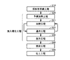
まず、リング状部材である転がり軸受の軌道輪(内輪)の製造方法を例に、本発明の一実施の形態である実施の形態1について説明する。図1を参照して、本実施の形態における内輪の製造方法では、まず工程(S10)として成形体準備工程が実施される。この工程(S10)では、たとえばJIS規格SUP13からなる鋼材が準備され、鍛造、旋削などの加工が実施されることにより、所望の内輪の形状に応じた形状を有するリング状の成形体が作製される。
(Embodiment 1)
First, Embodiment 1 which is one embodiment of the present invention will be described by taking as an example a method for manufacturing a ring (inner ring) of a rolling bearing that is a ring-shaped member. Referring to FIG. 1, in the inner ring manufacturing method according to the present embodiment, a molded body preparation step is first performed as a step (S <b> 10). In this step (S10), for example, a steel material made of JIS standard SUP13 is prepared, and by performing processing such as forging and turning, a ring-shaped formed body having a shape corresponding to the shape of the desired inner ring is produced. The
次に、図1を参照して、焼入硬化工程が実施される。この焼入硬化工程は、工程(S20)として実施される予備加熱工程と、工程(S21)として実施される加熱工程と、工程(S22)として実施される過冷工程と、工程(S30)として実施される急冷工程とを含んでいる。工程(S20)では、まず図2および図3を参照して、誘導加熱部材としてのコイル21が、工程(S10)において作製された成形体10において転動体が転走すべき面である転走面11の一部に面するように配置される。ここで、コイル21において転走面11に対向する面は、図3に示すように転走面11に沿った形状を有している。次に、成形体10が中心軸周り、具体的には矢印αの向きに回転されるとともに、コイル21に対して電源(図示しない)から高周波電流が供給される。これにより、成形体10の転走面11を含む表層領域が加熱される。
Next, with reference to FIG. 1, a quench hardening process is implemented. This quench hardening process includes a preliminary heating process performed as a process (S20), a heating process performed as a process (S21), a supercooling process performed as a process (S22), and a process (S30). And a quenching step to be performed. In step (S20), referring to FIG. 2 and FIG. 3, first, the
工程(S20)において転走面11がA1点以上の温度にまで加熱されると、鋼が強磁性体から常磁性体へと変化することに起因して、誘導加熱による発熱密度が低下する。そのため、転走面11がA1点以上の温度に加熱された時点、あるいは転走面11がA1点以上の温度に加熱されるよりも前の時点で工程(S20)を終了し、工程(S21)を開始する。
In the step (S20), when the rolling
工程(S21)では、コイル21に面する領域であって所望の硬化深さに対応する位置、たとえばコイル21に面する転走面11からの深さ7mmの位置における温度がA1点温度を超える状態にまで加熱される。具体的には、たとえば工程(S20)に比べて遅い速度で成形体10を回転させることにより、1回転あたりに転走面11の各領域がコイル21に面する時間を長くする。これにより、コイル21に面する領域を通過するごとに転走面11を含む表層部に与えられる熱量が大きくなり、たとえば転走面11からの深さ7mmの位置における温度がA1点温度を超える状態にまで加熱される。つまり、工程(S21)では成形体10の回転速度を工程(S20)の場合よりも小さくする。これによって、転走面11のうちコイル21に面する領域、およびその直下の表層部(たとえば深さ7mmまでの領域)がA1点温度を超える状態に加熱される。
In the step (S21), the temperature at the position corresponding to the desired hardening depth, for example, the position of 7 mm deep from the rolling
次に、工程(S22)では、成形体10が回転を続けることにより、工程(S21)において加熱された転走面11の領域はコイル21に面する位置から離脱し、当該領域の温度が低下する。そして、工程(S22)では、工程(S21)において加熱された転走面11およびその直下の表層部がA1点温度未満にまで冷却されるものの、過冷オーステナイト状態が維持された状態で再度コイル21に面する領域にまで到達する。これにより、工程(S22)が終了し、再度工程(S21)が実施される。つまり、工程(S20)が完了した後、成形体10が工程(S20)の場合よりも小さい速度で複数回回転することにより、工程(S21)および(S22)が複数回繰り返して実施される。これにより、鋼がオーステナイト状態を維持しつつ、A1点温度を超える状態に保持される時間が積算されていく。そして、成形体10の転走面11を含む領域に、鋼がオーステナイト化した環状の加熱領域11Aが形成されるとともに、炭素の母材への固溶状態が焼入に適した状態となった時点で工程(S21)および(S22)の繰り返しを終了し、工程(S30)が実施される。
Next, in the step (S22), as the compact 10 continues to rotate, the region of the rolling
工程(S30)では、工程(S20)〜(S22)において形成された加熱領域11Aを含む成形体10全体に対して、たとえば冷却液としての水が噴射されることにより、加熱領域11A全体がMS点以下の温度に同時に冷却される。これにより、加熱領域11Aがマルテンサイトに変態し、硬化する。以上の手順により、高周波焼入が実施され、焼入硬化工程が完了する。
In the step (S30), for example, water as a cooling liquid is sprayed on the entire molded
次に、工程(S40)として焼戻工程が実施される。この工程(S40)では、工程(S20)〜(S30)において焼入硬化された成形体10が、たとえば炉内に装入され、A1点以下の温度に加熱されて所定の時間保持されることにより、焼戻処理が実施される。
Next, a tempering step is performed as a step (S40). In this step (S40), a step (S20) ~ shaped
次に、工程(S50)として仕上工程が実施される。この工程(S50)では、たとえば転走面11に対して研磨加工などの仕上加工が実施される。以上のプロセスにより、転がり軸受の内輪が完成し、本実施の形態における内輪の製造は完了する。
Next, a finishing step is performed as a step (S50). In this step (S50), for example, a finishing process such as a polishing process is performed on the rolling
上記本実施の形態では、上記工程(S20)〜(S30)のプロセスによって焼入処理が実現されることにより、たとえコイル21によって加熱領域11A全体を同時にA1点温度を超える状態にする能力を焼入設備が有していなくても、加熱領域11A全体を同時に焼入硬化することができる。そのため、大型の成形体10を焼入硬化する場合でも、加熱領域11A全体を同時にA1点温度を超える状態にできるような大型のコイルや当該コイルに対応する大容量の電源を準備する必要がないため、焼入装置の製作コストを抑制することができる。
Above in the present embodiment, by quenching treatment by the process of the step (S20) ~ (S30) is achieved, the ability to state exceeding simultaneously A 1 point temperature across the
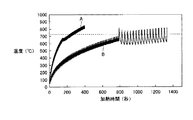
ここで、上記工程(S20)〜(S30)について、JIS規格SUP13からなり、内径d(図3参照)が1000mmを超えるリング状部材を準備し、上記実施の形態におけるプロセスを実際に実施した場合のデータを参照して、より詳細に説明する。図4は、転走面11から深さ7mmのある点における温度履歴を測定した結果を示しており、曲線Aは転走面11の周方向に沿って8個のコイルを並べて配置した場合、曲線Bは4個のコイルを並べて配置した場合を示している。また、図5は、曲線Bの工程(S21)および(S22)に対応する領域を拡大して示した図である。図6は、図5に対して最表面(すなわち転走面11)における温度履歴を示す曲線を重ねて示した図である。図4〜図6において、破線はA1点温度を示している。
Here, for the above steps (S20) to (S30), a ring-shaped member made of JIS standard SUP13 and having an inner diameter d (see FIG. 3) exceeding 1000 mm is prepared, and the process in the above embodiment is actually performed. This will be described in more detail with reference to the data. FIG. 4 shows the result of measuring the temperature history at a certain point 7 mm deep from the rolling
図4を参照して、転走面11の周方向に沿って8個のコイルを並べて配置した場合、加熱開始から250秒程度で測定位置における温度がA1点温度を超えている。そのため、曲線Aに対応する焼入設備が存在する場合、たとえば上記特許文献2に開示された方法により、加熱領域11A全体がA1点温度を超える状態に加熱して、焼入硬化処理を実施することができる。これに対し、転走面11の周方向に沿って4個のコイルを並べて配置した場合、同様の条件では加熱開始から800秒近く経過した時点でも、測定位置における温度がA1点温度に到達していない。そのため、加熱領域11A全体がA1点温度を超える状態に加熱する特許文献2の方法を採用することは困難である。
4, rolling when placed side by side eight coils along the circumferential direction of the
これに対し、図4および図5に示すように、温度がA1点温度に近づいた時点で成形体10の回転速度を低下させることにより工程(S20)を終了し、工程(S21)および(S22)に移行することができる。この工程(S21)および(S22)では、図4および図5に示すように、上記測定位置がA1点温度を超える状態と、A1点温度未満であって過冷オーステナイト状態が維持される温度の状態とを複数回繰り返すように加熱される。このとき、図6に示すように、最表面における温度が1000℃を超えることがないように、工程(S21)が実施されることが好ましい。これにより、転走面11における結晶粒の粗大化に起因した耐久性の低下を抑制することができる。
In contrast, as shown in FIGS. 4 and 5, the temperature is completed the step (S20) by lowering the rotational speed of the molded
図7は、SUP13のCCT(Continuous Cooling Transformation)線図に、工程(S21)および(S22)終了後、工程(S30)完了までの成形体10の温度履歴を重ねて描いた図である。図7には、転走面11から深さ7mmの領域における温度履歴が示されており、工程(S21)および(S22)終了時点において、コイル21に最も近い位置にあった領域の温度履歴が太線で、最も遠い位置にあった領域(コイル21による最後の加熱が完了して最も長い時間が経過していた領域)の温度履歴が細線で示されている。
FIG. 7 is a diagram in which the temperature history of the molded
図7に示すように、コイル21に最も近い位置にあった領域だけでなく、最も遠い位置にあった領域もパーライトノーズ(図中「P」で示す)およびベイナイトノーズ(図中「B」で示す)に触れることなく、Ms点以下の温度にまで冷却されている。このように工程(S30)を実施することにより、良好な焼入硬化層が形成される。
As shown in FIG. 7, not only the region closest to the
なお、成形体を構成する鋼としては種々の鋼を採用することができるが、上記実施の形態におけるプロセスに適した焼入性等を備える鋼、たとえば0.43質量%以上0.65質量%以下の炭素と、0.15質量%以上0.35質量%以下の珪素と、0.60質量%以上1.10質量%以下のマンガンと、0.30質量%以上1.20質量%以下のクロムと、0.15質量%以上0.75質量%以下のモリブデンとを含有し、残部鉄および不純物からなる鋼、あるいはこれに0.35質量%以上0.75質量%以下のニッケル添加した鋼を採用することが好ましい。具体的には、たとえばJIS規格SUP13、SCM445、SAE規格8660Hなどを採用することができる。 In addition, although various steel can be employ | adopted as steel which comprises a molded object, steel provided with the hardenability etc. which are suitable for the process in the said embodiment, for example, 0.43 mass% or more and 0.65 mass% The following carbon, 0.15 mass% or more and 0.35 mass% or less silicon, 0.60 mass% or more and 1.10 mass% or less manganese, 0.30 mass% or more and 1.20 mass% or less Steel containing chromium and 0.15 mass% or more and 0.75 mass% or less of molybdenum, and the balance iron and impurities, or steel with 0.35 mass% or more and 0.75 mass% or less of nickel added thereto Is preferably adopted. Specifically, for example, JIS standards SUP13, SCM445, SAE standards 8660H, etc. can be adopted.
また、上記工程(S21)および(S22)において、転走面11の各領域がA1点温度を超える状態に累積時間で1分間以上保持された後、工程(S30)が実施されることが好ましい。これにより、より確実に鋼を構成する炭素が母材に適切に固溶した状態で焼入処理を実施することができる。
In the above step (S21) and (S22), after each area of rolling
(実施の形態2)
次に、本発明の他の実施の形態である実施の形態2について説明する。実施の形態2におけるリング状部材としての内輪の製造方法は、基本的には実施の形態1の場合と同様に実施され、同様の効果を奏する。しかし、実施の形態2における内輪の製造方法は、工程(S20)におけるコイル21の配置において、実施の形態1の場合とは異なっている。
(Embodiment 2)
Next, Embodiment 2 which is another embodiment of the present invention will be described. The manufacturing method of the inner ring as the ring-shaped member in the second embodiment is basically performed in the same manner as in the first embodiment, and has the same effect. However, the inner ring manufacturing method according to the second embodiment is different from the first embodiment in the arrangement of the
すなわち、図8を参照して、実施の形態2における工程(S20)では、成形体10を挟んで一対のコイル21が配置される。そして、成形体10が矢印αの向きに回転されるとともに、コイル21に対して電源(図示しない)から高周波電流が供給される。
That is, with reference to FIG. 8, in the step (S20) in the second embodiment, a pair of
このように、コイル21が成形体10の周方向に沿って複数個(本実施の形態では2個)配置されることにより、実施の形態2における転がり軸受の内輪の製造方法は、上記工程(S22)において過冷オーステナイト状態を維持することが容易となっている。
Thus, the manufacturing method of the inner ring | wheel of the rolling bearing in Embodiment 2 by arrange | positioning the
なお、上記実施の形態においてはコイル21を固定し、成形体10を回転させる場合について説明したが、成形体10を固定し、コイル21を成形体10の周方向に回転させてもよいし、コイル21および成形体10の両方を回転させることにより、コイル21を成形体10の周方向に沿って相対的に回転させてもよい。ただし、コイル21には、コイル21に電流を供給する配線などが必要であるため、上述のようにコイル21を固定することが合理的である場合が多い。
In addition, in the said embodiment, although the case where the
また、上記実施の形態においては、リング状部材の一例としてラジアル型転がり軸受の内輪の熱処理および製造が実施される場合について説明したが、本発明を適用可能なリング状部材はこれに限られず、たとえばラジアル型転がり軸受の外輪であってもよいし、スラスト型軸受の軌道輪であってもよい。さらに、本発明を適用可能なリング状部材は軸受の軌道輪に限られず、鋼からなるリング状の種々の部材の熱処理および製造に、本発明を適用することができる。ここで、工程(S20)〜(S22)において、たとえばラジアル型転がり軸受の外輪を加熱する場合、コイル21を成形体の内周側に形成された転走面に面するように配置すればよい。また、工程(S20)〜(S22)において、たとえばスラスト型転がり軸受の軌道輪を加熱する場合、コイル21を成形体の端面側に形成された転走面に面するように配置すればよい。
Further, in the above embodiment, the case where the heat treatment and manufacture of the inner ring of the radial type rolling bearing is performed as an example of the ring-shaped member has been described, but the ring-shaped member to which the present invention is applicable is not limited thereto, For example, it may be an outer ring of a radial type rolling bearing or a raceway ring of a thrust type bearing. Furthermore, the ring-shaped member to which the present invention can be applied is not limited to the bearing ring, and the present invention can be applied to heat treatment and production of various ring-shaped members made of steel. Here, in the steps (S20) to (S22), for example, when the outer ring of the radial type rolling bearing is heated, the
さらに、上記実施の形態では、被処理物を部分的に焼入硬化することが可能な高周波焼入の特徴を利用して、転がり軸受の軌道輪の転走面を含む表層部のみを焼入硬化する部分焼入が実施される場合について説明したが、本発明は部分焼入のみに適用可能なものではなく、たとえば軌道輪の全体を焼入硬化する場合にも適用可能である。 Furthermore, in the above-described embodiment, only the surface layer portion including the rolling surface of the bearing ring of the rolling bearing is quenched by utilizing the feature of induction hardening that can partially quench and harden the workpiece. Although the case where the partial hardening which hardens | cures was implemented was demonstrated, this invention is not applicable only to partial hardening, For example, it can apply also when hardening and hardening the whole bearing ring.
また、成形体10の周方向におけるコイル21の長さは、適切な加熱を実現するように任意に決定することができるが、たとえば加熱すべき領域の長さの1/4以上1/1.5以下程度の長さとすることができる。複数のコイル21を用いる場合、コイル21の長さの合計値が上記範囲となればよい。
In addition, the length of the
(実施の形態3)
次に、リング状部材が風力発電装置用軸受(風力発電装置用転がり軸受)を構成する軌道輪として用いられる実施の形態3について説明する。
(Embodiment 3)
Next,
図9を参照して、風力発電装置50は、旋回翼であるブレード52と、ブレード52の中心軸を含むように、一端においてブレード52に接続された主軸51と、主軸51の他端に接続された増速機54とを備えている。さらに、増速機54は、出力軸55を含んでおり、出力軸55は、発電機56に接続されている。主軸51は、風力発電装置用転がり軸受である主軸用軸受3により、軸まわりに回転自在に支持されている。また、主軸用軸受3は、主軸51の軸方向に複数個(図9では2個)並べて配置されており、それぞれハウジング53により保持されている。主軸用軸受3、ハウジング53、増速機54および発電機56は、機械室であるナセル59の内部に格納されている。そして、主軸51は一端においてナセル59から突出し、ブレード52に接続されている。
Referring to FIG. 9,
次に、風力発電装置50の動作について説明する。図9を参照して、風力を受けてブレード52が周方向に回転すると、ブレード52に接続された主軸51は、主軸用軸受3によりハウジング53に対して支持されつつ、軸まわりに回転する。主軸51の回転は、増速機54に伝達されて増速され、出力軸55の軸まわりの回転に変換される。そして、出力軸55の回転は、発電機56に伝達され、電磁誘導作用により起電力が発生して発電が達成される。
Next, the operation of the
次に、風力発電装置50の主軸51の支持構造について説明する。図10を参照して、風力発電装置用転がり軸受としての主軸用軸受3は、風力発電装置用転がり軸受の軌道輪としての環状の外輪31と、外輪31の内周側に配置された風力発電装置用転がり軸受の軌道輪としての環状の内輪32と、外輪31と内輪32との間に配置され、円環状の保持器34に保持された複数のころ33とを備えている。外輪31の内周面には外輪転走面31Aが形成されており、内輪32の外周面には2つの内輪転走面32Aが形成されている。そして、2つの内輪転走面32Aが、外輪転走面31Aに対向するように、外輪31と内輪32とは配置されている。さらに、複数のころ33は、2つの内輪転走面32Aのそれぞれに沿って、外輪転走面31Aと内輪転走面32Aとに、ころ接触面33Aにおいて接触し、かつ保持器34に保持されて周方向に所定のピッチで配置されることにより複列(2列)の円環状の軌道上に転動自在に保持されている。また、外輪31には、外輪31を径方向に貫通する貫通孔31Eが形成されている。この貫通孔31Eを通して、外輪31と内輪32との間の空間に潤滑剤を供給することができる。以上の構成により、主軸用軸受3の外輪31および内輪32は、互いに相対的に回転可能となっている。
Next, a support structure for the
一方、ブレード52に接続された主軸51は、主軸用軸受3の内輪32を貫通するとともに、外周面51Aにおいて内輪の内周面32Fに接触し、内輪32に対して固定されている。また、主軸用軸受3の外輪31は、ハウジング53に形成された貫通孔の内壁53Aに外周面31Fにおいて接触するように嵌め込まれ、ハウジング53に対して固定されている。以上の構成により、ブレード52に接続された主軸51は、内輪32と一体に、外輪31およびハウジング53に対して軸まわりに回転可能となっている。
On the other hand, the
さらに、内輪転走面32Aの幅方向両端には、外輪31に向けて突出する鍔部32Eが形成されている。これにより、ブレード52が風を受けることにより発生する主軸51の軸方向(アキシャル方向)の荷重が支持される。また、外輪転走面31Aは、球面形状を有している。そのため、外輪31と内輪32とは、ころ33の転走方向に垂直な断面において、当該球面の中心を中心として互いに角度をなすことができる。すなわち、主軸用軸受3は、複列自動調心ころ軸受である。その結果、ブレード52が風を受けることにより主軸51が撓んだ場合であっても、ハウジング53は、主軸用軸受3を介して主軸51を安定して回転自在に保持することができる。
Further,
そして、実施の形態3における風力発電装置用転がり軸受の軌道輪としての外輪31および内輪32は、たとえば上記実施の形態1または2に記載のリング状部材の製造方法により製造されている。この外輪31および内輪32は、1000mm以上の内径を有する風力発電装置用転がり軸受の軌道輪である。このように、焼入装置の製作コストを抑制することが可能な製造方法により製造されることにより、外輪31および内輪32の製造コストを低減することができる。また、上記実施の形態1および2においては、加熱領域11A全体がMS点以下の温度に同時に冷却されて焼入硬化されるため、転走面(外輪転走面31Aおよび内輪転走面32A)を含む焼入硬化層を全周にわたって一様な深さに形成することが可能となり、耐久性に優れた外輪31および内輪32を得ることができる。
And the outer ring |
今回開示された実施の形態はすべての点で例示であって、制限的なものではないと考えられるべきである。本発明の範囲は上記した説明ではなくて特許請求の範囲によって示され、特許請求の範囲と均等の意味、および範囲内でのすべての変更が含まれることが意図される。 The embodiment disclosed this time is to be considered as illustrative in all points and not restrictive. The scope of the present invention is defined by the terms of the claims, rather than the description above, and is intended to include any modifications within the scope and meaning equivalent to the terms of the claims.
本発明のリング状部材の熱処理方法およびリング状部材の製造方法は、焼入装置の製作コストを抑制することが求められるリング状部材の熱処理方法およびリング状部材の製造方法に、特に有利に適用され得る。 The heat treatment method for a ring-shaped member and the method for producing the ring-shaped member of the present invention are particularly advantageously applied to a heat treatment method for a ring-shaped member and a method for producing the ring-shaped member that are required to reduce the manufacturing cost of the quenching apparatus. Can be done.
3 主軸用軸受、10 成形体、11 転走面、11A 加熱領域、21 コイル、31 外輪、31A 外輪転走面、31E 貫通孔、31F 外周面、32 内輪、32A 内輪転走面、32E 鍔部、32F 内周面、33 ころ、33A ころ接触面、34 保持器、50 風力発電装置、51 主軸、51A 外周面、52 ブレード、53 ハウジング、53A 内壁、54 増速機、55 出力軸、56 発電機、59 ナセル。 3 Bearing for spindle, 10 molded body, 11 rolling surface, 11A heating area, 21 coil, 31 outer ring, 31A outer ring rolling surface, 31E through hole, 31F outer peripheral surface, 32 inner ring, 32A inner ring rolling surface, 32E collar , 32F inner peripheral surface, 33 rollers, 33A roller contact surface, 34 cage, 50 wind power generator, 51 main shaft, 51A outer peripheral surface, 52 blade, 53 housing, 53A inner wall, 54 speed increaser, 55 output shaft, 56 power generation Machine, 59 nacelle.
Claims (10)
前記加熱領域全体をMS点以下の温度に同時に冷却する工程とを備え、
前記加熱領域を形成する工程では、前記周面の各領域がA1点温度を超える状態と、A1点温度未満であって過冷オーステナイト状態が維持される温度の状態とを複数回繰り返すように加熱される、リング状部材の熱処理方法。 By rotating the induction heating member that is arranged to face a part of the circumferential surface of the ring-shaped member made of steel and that induction-heats the ring-shaped member relatively along the circumferential direction of the ring-shaped member A step of forming an annular heating region in which the steel is austenitized in the ring-shaped member;
Simultaneously cooling the entire heating region to a temperature below the M S point,
In the step of forming the heating region, a state where each region of the peripheral surface exceeds the A 1 point temperature and a state where the temperature is less than the A 1 point temperature and the supercooled austenite state is maintained are repeated a plurality of times. A method for heat treatment of a ring-shaped member, which is heated by heating.
前記成形体を焼入硬化する工程とを備え、
前記成形体を焼入硬化する工程では、請求項1〜7のいずれか1項に記載のリング状部材の熱処理方法を用いて前記成形体を焼入硬化する、リング状部材の製造方法。 Preparing a ring-shaped formed body made of steel;
A step of quench hardening the molded body,
A method for manufacturing a ring-shaped member, wherein in the step of quenching and curing the molded body, the molded body is quenched and cured using the heat treatment method for a ring-shaped member according to any one of claims 1 to 7.
Priority Applications (6)
| Application Number | Priority Date | Filing Date | Title |
|---|---|---|---|
| JP2011237495A JP5775422B2 (en) | 2011-10-28 | 2011-10-28 | Heat treatment method for ring-shaped member and method for manufacturing ring-shaped member |
| EP12844543.4A EP2772555B1 (en) | 2011-10-28 | 2012-10-16 | Ring-shaped member heat treatment method and ring-shaped member manufacturing method |
| PCT/JP2012/076672 WO2013061822A1 (en) | 2011-10-28 | 2012-10-16 | Ring-shaped member heat treatment method and ring-shaped member manufacturing method |
| US14/354,816 US9181599B2 (en) | 2011-10-28 | 2012-10-16 | Method for heat-treating ring-shaped member and method for producing ring-shaped member |
| CN201280052764.4A CN103890201B (en) | 2011-10-28 | 2012-10-16 | The heat treatment method of annular component and the manufacture method of annular component |
| IN3559CHN2014 IN2014CN03559A (en) | 2011-10-28 | 2014-05-12 |
Applications Claiming Priority (1)
| Application Number | Priority Date | Filing Date | Title |
|---|---|---|---|
| JP2011237495A JP5775422B2 (en) | 2011-10-28 | 2011-10-28 | Heat treatment method for ring-shaped member and method for manufacturing ring-shaped member |
Publications (2)
| Publication Number | Publication Date |
|---|---|
| JP2013095939A JP2013095939A (en) | 2013-05-20 |
| JP5775422B2 true JP5775422B2 (en) | 2015-09-09 |
Family
ID=48167655
Family Applications (1)
| Application Number | Title | Priority Date | Filing Date |
|---|---|---|---|
| JP2011237495A Expired - Fee Related JP5775422B2 (en) | 2011-10-28 | 2011-10-28 | Heat treatment method for ring-shaped member and method for manufacturing ring-shaped member |
Country Status (6)
| Country | Link |
|---|---|
| US (1) | US9181599B2 (en) |
| EP (1) | EP2772555B1 (en) |
| JP (1) | JP5775422B2 (en) |
| CN (1) | CN103890201B (en) |
| IN (1) | IN2014CN03559A (en) |
| WO (1) | WO2013061822A1 (en) |
Families Citing this family (13)
| Publication number | Priority date | Publication date | Assignee | Title |
|---|---|---|---|---|
| CN104694729A (en) * | 2009-07-22 | 2015-06-10 | Ntn株式会社 | Method for heat-treating a ring-shaped member, method for producing a ring-shaped member, ring-shaped member, bearing ring, rolling bearing, and method for producing a bearing ring |
| US9487843B2 (en) | 2011-01-21 | 2016-11-08 | Ntn Corporation | Method for producing a bearing ring |
| JP6118629B2 (en) * | 2013-04-30 | 2017-04-19 | 株式会社三共 | Game machine |
| JP5995778B2 (en) * | 2013-04-30 | 2016-09-21 | 株式会社三共 | Game machine |
| JP6170720B2 (en) * | 2013-04-30 | 2017-07-26 | 株式会社三共 | Game machine |
| JP5995776B2 (en) * | 2013-04-30 | 2016-09-21 | 株式会社三共 | Game machine |
| JP6118630B2 (en) * | 2013-04-30 | 2017-04-19 | 株式会社三共 | Game machine |
| CN103343474B (en) * | 2013-06-25 | 2015-11-11 | 宝钢轧辊科技有限责任公司 | Felt wrapped roll roller shell and manufacture method thereof |
| DE112015005630T5 (en) * | 2014-12-16 | 2017-09-21 | Aktiebolaget Skf | Bearing component and method |
| CN104532140B (en) * | 2014-12-22 | 2016-05-11 | 北京科技大学 | A kind of large scale shield machine is steel and heat treatment method thereof for bearing ring |
| JP2017082944A (en) * | 2015-10-29 | 2017-05-18 | Ntn株式会社 | Process of manufacture of bearing ring and process of manufacture of double row conical roller bearing |
| EP3369953B1 (en) * | 2015-10-29 | 2021-09-29 | NTN Corporation | Multi-row tapered roller bearing |
| US11078961B2 (en) | 2018-04-02 | 2021-08-03 | Nsk Ltd. | Intermediary race member of rolling bearing, race, rolling bearing and production method therefor |
Family Cites Families (9)
| Publication number | Priority date | Publication date | Assignee | Title |
|---|---|---|---|---|
| JPS59118812A (en) | 1982-12-27 | 1984-07-09 | Nippon Seiko Kk | Method for hardening bearing ring of swiveling wheel bearing |
| JP4208426B2 (en) * | 2001-03-01 | 2009-01-14 | Ntn株式会社 | Induction hardening method and bearing parts |
| JP2005325409A (en) * | 2004-05-14 | 2005-11-24 | Ntn Corp | High frequency heat treatment method and device for ring-shaped product |
| JP4365311B2 (en) * | 2004-12-24 | 2009-11-18 | 高周波熱錬株式会社 | Induction heating coil and induction heating method for heating annular member from inner and outer periphery |
| DE102005006701B3 (en) * | 2005-02-15 | 2006-03-30 | Rothe Erde Gmbh | Production of bearing ring for large rolling bearing comprises arranging inductors over common zone of annular track to be hardened, heating the opposite-lying edge layer to the hardening temperature and further processing |
| JP2006265606A (en) * | 2005-03-23 | 2006-10-05 | Ntn Corp | High frequency induction heat-treatment method, high frequency induction heat-treatment facility and high frequency induction heat-treating article |
| JP2007231323A (en) * | 2006-02-28 | 2007-09-13 | Kyushu Institute Of Technology | Method for reforming surface of iron alloy-made structural part |
| JP5557235B2 (en) * | 2009-07-22 | 2014-07-23 | Ntn株式会社 | Heat treatment method for ring-shaped member, method for manufacturing ring-shaped member |
| CN104694729A (en) * | 2009-07-22 | 2015-06-10 | Ntn株式会社 | Method for heat-treating a ring-shaped member, method for producing a ring-shaped member, ring-shaped member, bearing ring, rolling bearing, and method for producing a bearing ring |
-
2011
- 2011-10-28 JP JP2011237495A patent/JP5775422B2/en not_active Expired - Fee Related
-
2012
- 2012-10-16 CN CN201280052764.4A patent/CN103890201B/en not_active Expired - Fee Related
- 2012-10-16 WO PCT/JP2012/076672 patent/WO2013061822A1/en active Application Filing
- 2012-10-16 US US14/354,816 patent/US9181599B2/en not_active Expired - Fee Related
- 2012-10-16 EP EP12844543.4A patent/EP2772555B1/en not_active Not-in-force
-
2014
- 2014-05-12 IN IN3559CHN2014 patent/IN2014CN03559A/en unknown
Also Published As
| Publication number | Publication date |
|---|---|
| IN2014CN03559A (en) | 2015-10-09 |
| EP2772555A1 (en) | 2014-09-03 |
| JP2013095939A (en) | 2013-05-20 |
| EP2772555A4 (en) | 2016-04-20 |
| EP2772555B1 (en) | 2018-12-19 |
| US9181599B2 (en) | 2015-11-10 |
| WO2013061822A1 (en) | 2013-05-02 |
| US20140305552A1 (en) | 2014-10-16 |
| CN103890201A (en) | 2014-06-25 |
| CN103890201B (en) | 2016-08-24 |
Similar Documents
| Publication | Publication Date | Title |
|---|---|---|
| JP5775422B2 (en) | Heat treatment method for ring-shaped member and method for manufacturing ring-shaped member | |
| WO2012098988A1 (en) | Method for manufacturing bearing ring, bearing ring, and rolling bearing | |
| WO2011010664A1 (en) | Method for heat-treating a ring-shaped member, method for producing a ring-shaped member, ring-shaped member, bearing ring, rolling bearing, and method for producing a bearing ring | |
| JP5773348B2 (en) | Method of manufacturing bearing ring, bearing ring and rolling bearing | |
| JP5665564B2 (en) | Manufacturing method of bearing ring | |
| JP6023493B2 (en) | Method of manufacturing bearing ring, bearing ring and rolling bearing | |
| JP2015180783A (en) | Bearing ring and method of producing rolling bearing | |
| JP5534403B2 (en) | Bearing rings and rolling bearings | |
| JP5557235B2 (en) | Heat treatment method for ring-shaped member, method for manufacturing ring-shaped member | |
| JP5455031B2 (en) | Manufacturing method of bearing ring and manufacturing method of rolling bearing | |
| JP2015212404A (en) | Manufacturing method of bearing ring, bearing ring and rolling shaft bearing | |
| JP5773349B2 (en) | Method of manufacturing bearing ring and rolling bearing | |
| WO2017203915A1 (en) | Heat treatment method for ring-shaped member, manufacturing method for ring-shaped member, bearing ring of roller bearing, and roller bearing | |
| JP2014095154A (en) | Heat treatment method for ring-shaped member, method for producing ring-shaped member, ring-shaped member, bearing ring of rolling bearing, and rolling bearing | |
| JP2015187310A (en) | Bearing ring production method, bearing ring, and rolling bearing | |
| JP2015193936A (en) | Bearing ring and method of producing rolling bearing | |
| JP6072145B2 (en) | Manufacturing method of bearing ring | |
| JP6178365B2 (en) | Manufacturing method of bearing ring, cylindrical roller bearing and tapered roller bearing | |
| JP2014025097A (en) | Method for manufacturing bearing ring, bearing ring and rolling bearing | |
| WO2017199872A1 (en) | Method for heat-treating ring-shaped member, method for manufacturing ring-shaped member, raceway of rolling bearing, and rolling bearing | |
| JP5665565B2 (en) | Manufacturing method of bearing ring | |
| JP5721449B2 (en) | Bearing rings and rolling bearings | |
| JP2015187311A (en) | Bearing ring production method, bearing ring, and rolling bearing | |
| JP2017082943A (en) | Process of manufacture of bearing ring and process of manufacture of double row conical roller bearing | |
| JP2017082300A (en) | Manufacturing method of bearing ring and double row tapered roller bearing |
Legal Events
| Date | Code | Title | Description |
|---|---|---|---|
| A621 | Written request for application examination |
Free format text: JAPANESE INTERMEDIATE CODE: A621 Effective date: 20140926 |
|
| TRDD | Decision of grant or rejection written | ||
| A01 | Written decision to grant a patent or to grant a registration (utility model) |
Free format text: JAPANESE INTERMEDIATE CODE: A01 Effective date: 20150609 |
|
| A61 | First payment of annual fees (during grant procedure) |
Free format text: JAPANESE INTERMEDIATE CODE: A61 Effective date: 20150703 |
|
| R150 | Certificate of patent or registration of utility model |
Ref document number: 5775422 Country of ref document: JP Free format text: JAPANESE INTERMEDIATE CODE: R150 |
|
| R250 | Receipt of annual fees |
Free format text: JAPANESE INTERMEDIATE CODE: R250 |
|
| R250 | Receipt of annual fees |
Free format text: JAPANESE INTERMEDIATE CODE: R250 |
|
| R250 | Receipt of annual fees |
Free format text: JAPANESE INTERMEDIATE CODE: R250 |
|
| R250 | Receipt of annual fees |
Free format text: JAPANESE INTERMEDIATE CODE: R250 |
|
| R250 | Receipt of annual fees |
Free format text: JAPANESE INTERMEDIATE CODE: R250 |
|
| LAPS | Cancellation because of no payment of annual fees |