WO2009128352A1 - インクの吐出方法 - Google Patents
インクの吐出方法 Download PDFInfo
- Publication number
- WO2009128352A1 WO2009128352A1 PCT/JP2009/056953 JP2009056953W WO2009128352A1 WO 2009128352 A1 WO2009128352 A1 WO 2009128352A1 JP 2009056953 W JP2009056953 W JP 2009056953W WO 2009128352 A1 WO2009128352 A1 WO 2009128352A1
- Authority
- WO
- WIPO (PCT)
- Prior art keywords
- ink
- nozzles
- nozzle
- ejection
- ejected
- Prior art date
- Legal status (The legal status is an assumption and is not a legal conclusion. Google has not performed a legal analysis and makes no representation as to the accuracy of the status listed.)
- Ceased
Links
Images


Classifications
-
- B—PERFORMING OPERATIONS; TRANSPORTING
- B41—PRINTING; LINING MACHINES; TYPEWRITERS; STAMPS
- B41J—TYPEWRITERS; SELECTIVE PRINTING MECHANISMS, i.e. MECHANISMS PRINTING OTHERWISE THAN FROM A FORME; CORRECTION OF TYPOGRAPHICAL ERRORS
- B41J2/00—Typewriters or selective printing mechanisms characterised by the printing or marking process for which they are designed
- B41J2/005—Typewriters or selective printing mechanisms characterised by the printing or marking process for which they are designed characterised by bringing liquid or particles selectively into contact with a printing material
- B41J2/01—Ink jet
- B41J2/015—Ink jet characterised by the jet generation process
- B41J2/04—Ink jet characterised by the jet generation process generating single droplets or particles on demand
- B41J2/045—Ink jet characterised by the jet generation process generating single droplets or particles on demand by pressure, e.g. electromechanical transducers
- B41J2/04501—Control methods or devices therefor, e.g. driver circuits, control circuits
- B41J2/04591—Width of the driving signal being adjusted
-
- B—PERFORMING OPERATIONS; TRANSPORTING
- B41—PRINTING; LINING MACHINES; TYPEWRITERS; STAMPS
- B41J—TYPEWRITERS; SELECTIVE PRINTING MECHANISMS, i.e. MECHANISMS PRINTING OTHERWISE THAN FROM A FORME; CORRECTION OF TYPOGRAPHICAL ERRORS
- B41J2/00—Typewriters or selective printing mechanisms characterised by the printing or marking process for which they are designed
- B41J2/005—Typewriters or selective printing mechanisms characterised by the printing or marking process for which they are designed characterised by bringing liquid or particles selectively into contact with a printing material
- B41J2/01—Ink jet
- B41J2/015—Ink jet characterised by the jet generation process
- B41J2/04—Ink jet characterised by the jet generation process generating single droplets or particles on demand
- B41J2/045—Ink jet characterised by the jet generation process generating single droplets or particles on demand by pressure, e.g. electromechanical transducers
- B41J2/04501—Control methods or devices therefor, e.g. driver circuits, control circuits
- B41J2/04525—Control methods or devices therefor, e.g. driver circuits, control circuits reducing occurrence of cross talk
-
- B—PERFORMING OPERATIONS; TRANSPORTING
- B41—PRINTING; LINING MACHINES; TYPEWRITERS; STAMPS
- B41J—TYPEWRITERS; SELECTIVE PRINTING MECHANISMS, i.e. MECHANISMS PRINTING OTHERWISE THAN FROM A FORME; CORRECTION OF TYPOGRAPHICAL ERRORS
- B41J2/00—Typewriters or selective printing mechanisms characterised by the printing or marking process for which they are designed
- B41J2/005—Typewriters or selective printing mechanisms characterised by the printing or marking process for which they are designed characterised by bringing liquid or particles selectively into contact with a printing material
- B41J2/01—Ink jet
- B41J2/015—Ink jet characterised by the jet generation process
- B41J2/04—Ink jet characterised by the jet generation process generating single droplets or particles on demand
- B41J2/045—Ink jet characterised by the jet generation process generating single droplets or particles on demand by pressure, e.g. electromechanical transducers
- B41J2/04501—Control methods or devices therefor, e.g. driver circuits, control circuits
- B41J2/04535—Control methods or devices therefor, e.g. driver circuits, control circuits involving calculation of drop size, weight or volume
-
- B—PERFORMING OPERATIONS; TRANSPORTING
- B41—PRINTING; LINING MACHINES; TYPEWRITERS; STAMPS
- B41J—TYPEWRITERS; SELECTIVE PRINTING MECHANISMS, i.e. MECHANISMS PRINTING OTHERWISE THAN FROM A FORME; CORRECTION OF TYPOGRAPHICAL ERRORS
- B41J2/00—Typewriters or selective printing mechanisms characterised by the printing or marking process for which they are designed
- B41J2/005—Typewriters or selective printing mechanisms characterised by the printing or marking process for which they are designed characterised by bringing liquid or particles selectively into contact with a printing material
- B41J2/01—Ink jet
- B41J2/015—Ink jet characterised by the jet generation process
- B41J2/04—Ink jet characterised by the jet generation process generating single droplets or particles on demand
- B41J2/045—Ink jet characterised by the jet generation process generating single droplets or particles on demand by pressure, e.g. electromechanical transducers
- B41J2/04501—Control methods or devices therefor, e.g. driver circuits, control circuits
- B41J2/04581—Control methods or devices therefor, e.g. driver circuits, control circuits controlling heads based on piezoelectric elements
-
- B—PERFORMING OPERATIONS; TRANSPORTING
- B41—PRINTING; LINING MACHINES; TYPEWRITERS; STAMPS
- B41J—TYPEWRITERS; SELECTIVE PRINTING MECHANISMS, i.e. MECHANISMS PRINTING OTHERWISE THAN FROM A FORME; CORRECTION OF TYPOGRAPHICAL ERRORS
- B41J2/00—Typewriters or selective printing mechanisms characterised by the printing or marking process for which they are designed
- B41J2/005—Typewriters or selective printing mechanisms characterised by the printing or marking process for which they are designed characterised by bringing liquid or particles selectively into contact with a printing material
- B41J2/01—Ink jet
- B41J2/015—Ink jet characterised by the jet generation process
- B41J2/04—Ink jet characterised by the jet generation process generating single droplets or particles on demand
- B41J2/045—Ink jet characterised by the jet generation process generating single droplets or particles on demand by pressure, e.g. electromechanical transducers
- B41J2/04501—Control methods or devices therefor, e.g. driver circuits, control circuits
- B41J2/04588—Control methods or devices therefor, e.g. driver circuits, control circuits using a specific waveform
-
- B—PERFORMING OPERATIONS; TRANSPORTING
- B41—PRINTING; LINING MACHINES; TYPEWRITERS; STAMPS
- B41J—TYPEWRITERS; SELECTIVE PRINTING MECHANISMS, i.e. MECHANISMS PRINTING OTHERWISE THAN FROM A FORME; CORRECTION OF TYPOGRAPHICAL ERRORS
- B41J2/00—Typewriters or selective printing mechanisms characterised by the printing or marking process for which they are designed
- B41J2/005—Typewriters or selective printing mechanisms characterised by the printing or marking process for which they are designed characterised by bringing liquid or particles selectively into contact with a printing material
- B41J2/01—Ink jet
- B41J2/015—Ink jet characterised by the jet generation process
- B41J2/04—Ink jet characterised by the jet generation process generating single droplets or particles on demand
- B41J2/045—Ink jet characterised by the jet generation process generating single droplets or particles on demand by pressure, e.g. electromechanical transducers
- B41J2/04501—Control methods or devices therefor, e.g. driver circuits, control circuits
- B41J2/0459—Height of the driving signal being adjusted
Definitions
- the present invention relates to an ink discharge method, and more specifically, using a head including a liquid chamber filled with ink, a pressure generating element that changes the pressure in the liquid chamber, and a nozzle provided in the liquid chamber.
- the present invention relates to an ink ejection method for ejecting ink from nozzles.
- the coating film is processed into a desired pattern by photolithography.
- the photolithography method has problems that the process is complicated and the metal material to be used is wasted.
- a metal ink is also applied on a substrate by an ink jet method (for example, see Patent Document 1).
- an ink jet method for example, see Patent Document 1
- a coating film having a desired pattern can be directly formed on the substrate. Therefore, compared to the above-described method, not only can the process be shortened, but also the waste of the metal ink to be used can be reduced.
- an apparatus that controls ink ejection by a pressure generating element such as a piezo element (piezoelectric element)
- the head often has a plurality of nozzles and pressure generating elements.
- the pressure generating element causes ink to be ejected using mechanical distortion generated by applying a pulse voltage between the electrodes.
- Each nozzle is divided into a plurality of sections, and further divided into drive blocks within each section.
- the pressure generating element is time-division driven for each drive block.
- the nozzles provided in the head have individual differences due to dimensional variations during manufacturing. For this reason, the amount of ink ejected from each nozzle is not uniform and varies among nozzles. In addition, there is a variation in the ink ejection speed, and a difference occurs in the ink landing position on the substrate depending on the nozzle. If there is a variation in the amount of ink discharged, the dot diameter of the ink that has landed on the substrate varies, resulting in uneven density. In addition, if the ink landing position varies, the pattern accuracy of the coating film is lowered.
- the discharge amount and the discharge speed are made uniform by adjusting the applied voltage. That is, when a voltage is applied to the pressure generating element, its shape changes at a high speed in proportion to the magnitude of the electric field. Therefore, by changing the magnitude and voltage waveform of the voltage applied to the pressure generating element, it is possible to change the ink discharge amount and the discharge speed so that they are uniform (see Patent Document 2).
- the above-described head having a plurality of nozzles has an advantage that ink can be applied to an object such as a substrate at high speed.
- the nozzles are divided into a plurality of blocks, and a predetermined number of nozzles are time-division driven for each block.
- ink is ejected from a plurality of nozzles in order from the end along the direction in which the nozzles are arranged.
- the degree of interference between the nozzles varies depending on the coating pattern formed on the object. This is because when the application pattern is different, the ejection period of each nozzle and the phase difference between the nozzles of the drive waveform of the voltage applied to the pressure generating element change.
- an adjustment application timing has been used when adjusting the voltage applied to the pressure generating element in order to make the discharge amount and discharge speed of ink at each nozzle uniform. For this reason, if it is applied at the actual application timing, there is a problem that a new interference action is added between the nozzles and a desired pattern cannot be formed.
- an object of the present invention is to provide an ink discharge method that can be applied in a desired pattern using a head having a plurality of nozzles.
- the present invention uses a head including a liquid chamber filled with ink, a pressure generating element that changes the pressure in the liquid chamber, and a nozzle provided in the liquid chamber to discharge the ink from the nozzle.
- the head includes a plurality of the nozzles,
- the ink is ejected under the same conditions as for the actual coating pattern, and the drive waveform of the voltage applied to the pressure generating element is set so that at least one of the ink ejection amount and ejection speed from each nozzle is uniform. It is characterized by having a process of changing every time.
- the step is a step of obtaining an average value of ejection amount and ejection speed for a plurality of ink droplets ejected from the same nozzle, and making the average value uniform among the nozzles. Is preferred.
- At least one of the ejection amount and the ejection speed may be achieved by irradiating the ink droplets ejected from the nozzle with illumination light that emits light in synchronization with the ejection timing of the ink droplets. And can be obtained based on the obtained image.
- each of the plurality of nozzles can be discharged with a time difference.
- the voltage applied to the pressure generating element is such that ink is ejected under the same conditions as for the actual coating pattern and at least one of the ink ejection amount and ejection speed from each nozzle is uniform. Since the driving waveform is changed for each nozzle, even a head having a plurality of nozzles can be applied in a desired pattern.
- (A) And (b) is a partial block diagram of the inkjet coating device in this Embodiment. In this Embodiment, it is a schematic diagram which shows the correspondence of a board
- (A)-(c) is an example of the pulse waveform applied to the pressure generating element in the conventional adjustment method.
- (A) to (c) are examples of pulse waveforms according to the present embodiment.
- the head includes a liquid chamber filled with ink, a nozzle provided in the liquid chamber and ejected with ink, and a pressure generating element that changes the pressure in the liquid chamber.
- the pressure generating element include a piezoelectric element (piezoelectric element). When a voltage is applied to the pressure generating element, the pressure in the liquid chamber changes and droplets are ejected from the nozzle.
- the number of heads may be one or two or more.
- the nozzles and the pressure generating elements are each provided in the head in a number of 2 or more.
- the pressure generating element ejects ink using mechanical distortion generated by applying a pulse voltage between electrodes.
- Each nozzle is divided into a plurality of sections, and further divided into drive blocks within each section.
- the pressure generating element is time-division driven for each drive block.
- ink is ejected from a plurality of nozzles in order from the end along the direction in which the nozzles are arranged.
- the time required for coating can be shortened, and the drive circuit can be simplified.
- the ink jet coating apparatus has a control device that adjusts a driving waveform of a voltage applied to the pressure generating element.
- This control device can adjust the drive waveform in two directions, the voltage direction and the time direction.
- the control device may adjust the drive waveform only in one of the voltage direction and the time direction.
- the inkjet coating apparatus has a discharge state observation apparatus.
- This apparatus is means for observing the ejection state of ink droplets ejected from nozzles.
- the same conditions as the actual application that is, the discharge period of each nozzle and the phase difference between the nozzles of the drive waveform of the voltage applied to the pressure generating element are the same as the conditions for the actual application pattern, It is a means for observing the discharge state.
- the ink droplets ejected from the nozzles are irradiated with illumination light that emits light in synchronization with the ejection timing of the ink droplets, the ink droplets are imaged with a camera, and the ejection amount is based on the obtained image And a discharge speed can be obtained.
- a strobe can be used as the illumination light source, and a CCD camera can be used as the camera.
- FIGS. 1A and 1B are examples of a partial configuration diagram of the ink jet coating apparatus according to the present embodiment.
- FIG. 1A is a diagram viewed from a direction perpendicular to the ink dropping direction
- FIG. 1B is a diagram viewed from the nozzle direction.
- reference numeral 1 denotes a head.
- a liquid chamber filled with ink, a pressure generating element for changing the pressure in the liquid chamber, and a liquid chamber are provided.
- Nozzle The number of nozzles is two or more, and ink in the liquid chamber is ejected from these nozzles. (In the example of FIG.
- reference numeral 2 denotes an ejection state observation device that receives light from the strobe 3 that emits light and light from the strobe 3.
- a CCD camera 4 that picks up ink droplets, and a discharge speed acquisition unit 5 that acquires the ink discharge speed.
- ink is ejected under the same conditions as for the actual application pattern, that is, under the same conditions as the actual application, and the ejection amount and ejection speed are adjusted.
- the adjustment is performed by the control device, and specifically by DPN (Drive Per Nozzle) correction. That is, the discharge amount and the discharge speed are obtained for each nozzle, compared with the target values, and the correction coefficient obtained in advance from each relationship between the discharge amount, the discharge speed, and the drive waveform is used so that these become the target values. Then, the drive waveform of each voltage is adjusted for each nozzle.
- DPN Drive Per Nozzle
- the above adjustment is performed by changing the magnitude and time width of the pulse voltage for driving the pressure generating element.
- the discharge rate can be made uniform by making the discharge speed uniform.
- the discharge amount is adjusted to be uniform, and then the discharge speed is adjusted to be uniform. In this way, by adjusting in two steps, it is possible to control the ink ejection amount and ejection speed with high accuracy.
- the adjustment of the ink ejection amount is performed by changing the driving waveform of the voltage applied to the pressure generating element in the voltage direction.
- it can be performed as follows.
- Ink is ejected under the same conditions as for the actual application pattern, and the ink droplets ejected from the nozzles 13, 14 and 15 are imaged by the ejection state observation device 2.
- the strobe 3 is caused to emit light in synchronization with the ejection of the ink droplet, and the flying ink droplet is imaged by the CCD camera 4.
- the discharge amount is compared based on the obtained image, and the drive waveform is changed for each nozzle 13, 14, 15 in the control device 6 so that the discharge amount becomes uniform at the nozzles 13, 14, 15 respectively. If the relationship between the size of the ink droplet and the discharge amount is obtained in advance, the desired discharge amount of ink can be uniformly discharged from the nozzles 13, 14, and 15.
- the discharge amount can also be known by examining the dot diameter of the ink after the ink droplets discharged from the nozzles have landed on the target substrate or the like. Specifically, ink is ejected onto the substrate under the same conditions as for the actual application pattern. Then, the dot diameters of the ink ejected from the nozzles are compared, and the drive waveform is changed in the voltage direction by the control device so that they have a desired size uniformly. If the relationship between the dot diameter and the discharge amount is determined in advance, a desired discharge amount of ink can be uniformly discharged from each nozzle. However, since the dot diameter of the ink is affected by the surface condition of the substrate, the method obtained from the above-described captured image is preferable.
- the discharge speed is made uniform for the ink droplets having a uniform discharge amount. Specifically, it is performed by changing the drive waveform of the voltage applied to the pressure generating element in the time direction. For example, it can be performed as follows.
- Ink is ejected under the same conditions as for the actual application pattern, and the ink droplets ejected from the nozzles 13, 14, and 15 are imaged twice at different timings by the ejection state observation device 2.
- the strobe 3 synchronized with the driving pulse of the voltage applied to the pressure generating element blinks twice, and the flying ink droplet is imaged by the CCD camera 4.
- the ejection speed acquisition unit 5 the position of the ink droplet is obtained from the obtained image, and the ink ejection speed is obtained from the position and the interval of the imaging timing.
- the control device 6 compares the ejection speed of the ink ejected from the nozzles 13, 14, and 15. And a drive waveform is changed by the control apparatus 6 for every nozzle 13,14,15 so that these may become uniform.
- the discharge speed can also be known by examining the position where the ink droplets discharged from the nozzles land on the substrate as the object. This is because if the discharge speed is high, it will land at a position far from the nozzle, while if the discharge speed is low, it will land at a position near the nozzle. In the present embodiment, the discharge speed may be compared by this method. However, since the landing position may be influenced by the surface state of the substrate, the method obtained from the captured image described above is preferable.
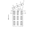
- FIG. 2 schematically shows a substrate and a head, where 11 is a head and 12 is a substrate. Moreover, in this figure, the arrow has shown the direction to which the head 11 moves. The substrate and the head may be moved relatively, and the substrate may be moved in the direction opposite to the arrow with the head fixed.
- FIG. 2 shows the positional relationship between the head and the pattern when the actual coating pattern is used.
- reference numeral 101 denotes a position where ink ejected from the nozzle 13 should land. In this example, three drops of ink land to form one pattern 102, and the same pattern is sequentially formed in the direction of the arrow as the head 11 moves.
- reference numeral 103 denotes a position where ink ejected from the nozzle 14 should land, and three drops of ink land to form a pattern 104.
- Reference numeral 105 denotes a position where the ink ejected from the nozzle 15 should land, and three drops of ink land to form the pattern 106.
- FIG. 3A and 3B show pulse waveforms applied to the pressure generating element in the conventional adjustment method.
- FIG. 3A shows the nozzle 13 shown in FIG. 1
- FIG. 3B shows the nozzle 14 shown in FIG.
- Each corresponds to the nozzle 15 in FIG.
- the horizontal axis represents time and the vertical axis represents voltage.
- the pulse waveforms are applied to the nozzles 13, 14, and 15 at the same timing (see FIG. 20 and Patent Document 2). (See paragraph 0052.)
- the application unevenness cannot be eliminated if the pulse waveforms are applied to the nozzles 13, 14 and 15 at the same timing.
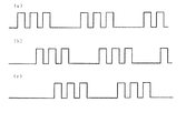
- FIG. 4 shows pulse waveforms in the present embodiment.
- (A) shows the nozzle 13 of FIG. 2
- (b) shows the nozzle 14 of FIG. 2
- (c) shows the nozzle 15 of FIG.
- the pulse waveform is out of phase between the nozzles. This is because, in actual application, the head is disposed obliquely in order to match the pattern pitch. The timing at this time is used for adjustment in FIG.
- each of the plurality of nozzles is ejected with a time difference, so that the ink ejection amount and the ejection speed can be made uniform while considering the interference between the nozzles corresponding to the actual application pattern. It becomes possible.
- the discharge amount can be adjusted by individually adjusting the timing of the pulse waveforms in FIGS. 4A to 4C, the adjustment of the voltage direction of the pulse waveform, the voltage application time, and the rise and / or fall of the pulse waveform. Uniformity and uniform discharge speed can be achieved. As described above, these operations are performed by the control device 6. Further, it is not necessary to make both the discharge amount and the discharge speed uniform, and the effect of the present invention can be obtained even when either one is made uniform.
- the strobe when capturing an ink droplet flying to obtain the ejection speed, the strobe flashes in consideration of the phase difference of the pulse waveform, and the CCD camera captures the image. . That is, since the pulse waveform between nozzles has a predetermined phase difference, an image of an ink droplet ejected from one nozzle and then an image of an ink droplet ejected from another nozzle are input to the strobe. The trigger signal is shifted by the phase difference calculated from the coating pattern. As a result, the ink droplets ejected from each nozzle can always be imaged by the CCD camera.
- the trigger signal input to the strobe is shifted by the phase difference corresponding to the coating pattern, and the average value of the discharge amount and discharge speed is calculated for a plurality of ink droplets. It is preferable to make the value uniform among the nozzles. By doing so, it becomes possible to control the ink ejection state with higher accuracy.
- the ink is ejected under the same conditions as the actual application pattern, that is, under the same conditions as the actual application, and the discharge amount and the discharge speed are adjusted to correspond to the actual application pattern. Adjustment in consideration of interference between nozzles becomes possible. Therefore, even with a head having a large number of nozzles, it is possible to reduce coating unevenness and form a desired pattern.
- the ejection speed is adjusted after adjusting the ejection amount of the ink ejected from each nozzle.
- the present invention is not limited to this, and the discharge amount may be adjusted after adjusting the discharge speed. In this case, each adjustment can be performed by the same method as described above.
Landscapes
- Coating Apparatus (AREA)
- Application Of Or Painting With Fluid Materials (AREA)
- Ink Jet (AREA)
Abstract
複数のノズルを有するヘッドを用いて、所望のパターンで塗布することのできるインクの吐出方法を提供する。 ヘッド1内には、インクが充填される液室内の圧力を変化させる圧力発生素子があり、液室には、インクを吐出するノズル13,14,15が設けられている。実際の塗布パターンに対するのと同じ条件でノズル13,14,15から吐出されたインク滴は、吐出状態観測装置2で吐出量および吐出速度が求められ、得られた情報は制御装置6に送られる。制御装置6では、インクの吐出量と吐出速度の少なくとも一方がノズル13,14,15で均一になるように、圧力発生素子に印加される電圧の駆動波形を変化させる。
Description
本発明は、インクの吐出方法に関し、より詳しくは、インクが充填される液室と、液室内の圧力を変化させる圧力発生素子と、液室に設けられたノズルとを備えたヘッドを用いて、ノズルからインクを吐出するインクの吐出方法に関する。
従来より、真空蒸着法やスパッタリング法などで基板の全面に金属膜を成膜した後、フォトリソグラフィ法によって、塗布膜を所望のパターンに加工することが行われている。しかし、フォトリソグラフィ法は、工程が煩雑である上に、使用する金属材料の無駄が大きいという問題を有する。
これに対して、インクジェット法によって、基板上に金属インクを塗布することも行われている(例えば、特許文献1参照。)。この方法によれば、所望のパターンを有する塗布膜を、基板上に直接形成できる。したがって、上記した方法に比べて、工程を短縮できるだけでなく、使用する金属インクの無駄を減らすこともできる。
インクジェット塗布装置としては、ピエゾ素子(圧電素子)などの圧力発生素子によってインクの吐出を制御するものが知られている。この装置では、ヘッドが、ノズルと圧力発生素子とをそれぞれ複数有していることが多い。圧力発生素子は、電極間にパルス電圧を印加することにより生じる機械的歪みを利用してインクを吐出させる。各ノズルは、複数のセクションに分けられており、さらに各セクション内で駆動ブロックに分割されている。そして、駆動ブロック毎に圧力発生素子が時分割駆動される。
ところで、ヘッドに設けられたノズルには、製造時の寸法ばらつきなどに起因する個体差がある。このため、各ノズルから吐出されるインクの量は均一でなく、ノズル間でばらつきがある。また、インクの吐出速度にもばらつきがあり、ノズルによって基板へのインクの着弾位置に違いが生じる。インクの吐出量にばらつきがあると、基板上に着弾したインクのドット径がばらついて濃度むらになる。また、インクの着弾位置にばらつきがあると、塗布膜のパターン精度を低下させる結果となる。
しかし、各ノズルのばらつきが問題のない程度まで抑えられたノズルを製造することは、歩留まりを極端に低下させることになる。また、製造当初はばらつきが小さくても、動作を繰り返しているうちに何らかの原因でばらつきが大きくなってしまうこともある。
そこで、インクの吐出量と吐出速度がノズル間で均一になるように、これらを調整することが必要になる。圧力発生素子を用いたインクジェット塗布装置では、印加電圧を調整することによって、吐出量と吐出速度が均一になるようにしている。すなわち、圧力発生素子に電圧を印加すると、電界の大きさに比例して、速い速度でその形状が変化する。それ故、圧力発生素子に印加する電圧の大きさや電圧波形を変えることにより、インクの吐出量や吐出速度を変えて、これらが均一となるようにすることができる(特許文献2参照)。
上述した複数のノズルを有するヘッドには、基板などの対象物にインクを高速で塗布できるという利点がある。かかるヘッドを有するインクジェット塗布装置では、ノズルが複数のブロックに分割されていて、ブロック毎に所定の数のノズルが時分割駆動される。一般には、ノズルが並んでいる方向に沿って、端から順に複数のノズルからインクが吐出するようになっている。
しかし、ノズルの数が多くなると、隣接するノズル同士の間隔が近くなるために、ノズル間で干渉(クロストーク)が生じ、これによりインクの吐出状態が変化する。こうした干渉は、複数のノズル単位でノズルの配列方向に沿って順次インクを吐出させる方式で顕著となる。複数のノズル内での干渉とは別に、複数のノズル間での干渉も生じるからである。
ところで、ノズル間での干渉の程度は、対象物上に形成する塗布パターンによって異なる。これは、塗布パターンが異なると、各ノズルの吐出周期や、圧力発生素子に印加する電圧の駆動波形のノズル間における位相差が変わることによる。しかしながら、従来、各ノズルにおけるインクの吐出量や吐出速度を均一にするため、圧力発生素子に印加する電圧を調整する際には、調整用の塗布タイミングが用いられていた。このため、実際の塗布タイミングで塗布すると、ノズル間での新たな干渉作用が加わり、所望のパターンを形成できなくなるという問題があった。
本発明は、こうした点に鑑みてなされたものである。すなわち、本発明の目的は、複数のノズルを有するヘッドを用いて、所望のパターンで塗布することのできるインクの吐出方法を提供することにある。
本発明の他の目的および利点は、以下の記載から明らかとなるであろう。
本発明は、インクが充填される液室と、前記液室内の圧力を変化させる圧力発生素子と、前記液室に設けられたノズルとを備えたヘッドを用いて、前記ノズルから前記インクを吐出するインクの吐出方法において、
前記ヘッドは前記ノズルを複数備えており、
実際の塗布パターンに対するのと同じ条件でインクを吐出して、各ノズルからのインクの吐出量および吐出速度の少なくとも一方が均一になるように、前記圧力発生素子に印加する電圧の駆動波形をノズル毎に変化させる工程を有することを特徴とするものである。
本発明において、前記工程は、同一のノズルから吐出された複数のインク滴について吐出量と吐出速度の平均値を求め、これらの平均値が各ノズル間で均一になるようにする工程とすることが好ましい。
本発明において、前記吐出量および前記吐出速度の少なくとも一方は、前記ノズルから吐出されたインク滴に、前記インク滴の吐出タイミングと同期して発光する照明光を照射して、前記インク滴をカメラで撮像し、得られた画像に基づいて求められ得る。
本発明においては、前記複数のノズルのそれぞれの吐出を時間差を有して行うことができる。
本発明によれば、実際の塗布パターンに対するのと同じ条件でインクを吐出して、各ノズルからのインクの吐出量および吐出速度の少なくとも一方が均一になるように、圧力発生素子に印加する電圧の駆動波形をノズル毎に変化させるので、複数のノズルを有するヘッドであっても所望のパターンで塗布することが可能となる。
本実施の形態におけるインクジェット塗布装置では、ヘッドが、インクが充填される液室と、この液室に設けられてインクが吐出されるノズルと、液室内の圧力を変化させる圧力発生素子とを備える。ここで、圧力発生素子としては、ピエゾ素子(圧電素子)などが挙げられる。圧力発生素子に電圧を印加すると、液室内の圧力が変化してノズルから液滴が吐出する。尚、ヘッドの数は、1つであってもよいし、2つ以上であってもよい。
本実施の形態では、ノズルと圧力発生素子とが、それぞれ2以上の数でヘッドに設けられている。圧力発生素子は、電極間にパルス電圧を印加することにより生じる機械的歪みを利用してインクを吐出させるものである。各ノズルは、複数のセクションに分けられており、さらに各セクション内で駆動ブロックに分割されている。そして、駆動ブロック毎に圧力発生素子が時分割駆動される。
本実施の形態においては、ノズルが並んでいる方向に沿って、端から順に複数のノズルからインクが吐出するように駆動することができる。これにより、塗布に要する時間を短くできるとともに、駆動回路を簡素化することができる。
インクジェット塗布装置は、圧力発生素子に印加する電圧の駆動波形を調整する制御装置を有する。この制御装置は、駆動波形を電圧方向と時間方向の2方向に調整することができる。尚、制御装置は、駆動波形を電圧方向および時間方向のいずれか一方にのみ調整するものであってもよい。
また、インクジェット塗布装置は、吐出状態観測装置を有する。この装置は、ノズルから吐出されたインク滴の吐出状態を観測する手段である。換言すると、実際に塗布するのと同じ条件、すなわち、各ノズルの吐出周期や、圧力発生素子に印加する電圧の駆動波形のノズル間における位相差を、実際の塗布パターンに対する条件と同じにして、吐出状態を観測する手段である。
吐出状態観測装置では、ノズルから吐出されたインク滴に、インク滴の吐出タイミングと同期して発光する照明光を照射して、インク滴をカメラで撮像し、得られた画像に基づいて吐出量や吐出速度が求められるようにすることができる。ここで、照明光の光源としてはストロボを用いることができ、カメラとしてはCCDカメラを用いることができる。
図1(a)および(b)は、本実施の形態におけるインクジェット塗布装置の部分構成図の一例である。図1(a)は、インクの滴下方向に対して垂直な方向から見た図であり、図1(b)は、ノズルの方向から見た図である。尚、図1(b)では、制御装置および各構成部材間の接続の一部を省略している。図1(a)および(b)において、1はヘッドであり、詳細は図示しないが、インクが充填される液室と、この液室内の圧力を変化させる圧力発生素子と、液室に設けられたノズルとを備える。ノズルは2以上の数で設けられており、これらのノズルから液室内のインクが吐出される。(図1の例では、3つのノズル13,14,15が設けられている。)また、2は、吐出状態観測装置であり、光を照射するストロボ3と、ストロボ3からの光を受光してインク滴を撮像するCCDカメラ4と、インクの吐出速度を取得する吐出速度取得部5とを備えている。
上述したように、ノズル13,14,15から吐出されるインクの吐出量にばらつきがあると、基板などの対象物上に着弾したインクのドット径がばらついて濃度むらになる。また、インクの吐出速度にばらつきがあると、インクの着弾位置にばらつきが生じる。したがって、本番の塗布を行う前に、吐出量や吐出速度が均一になるよう調整する必要がある。
本実施の形態では、実際の塗布パターンに対するのと同じ条件、すなわち、本番の塗布と同じ条件でインクを吐出して、吐出量や吐出速度の調整を行う。調整は、制御装置で行い、具体的にはDPN(Drive Per Nozzle)補正によって行う。すなわち、ノズル毎に吐出量と吐出速度を求めて目標値と比較し、これらが目標値となるように、吐出量および吐出速度と駆動波形との各関係から予め求めておいた補正係数を用いて、それぞれの電圧の駆動波形をノズル毎に調整する。
上記の調整は、圧力発生素子を駆動するパルス電圧の大きさや時間幅を変えることによって行う。ここで、ノズル数が少ない場合には、吐出速度を均一化することにより、吐出量も均一化することができる。しかし、ノズル数が多くなると、吐出速度を均一化しても、吐出量の均一化を図ることができなくなる。そこで、ノズル数が多い場合には、まず、吐出量が均一となるように調整し、次いで、吐出速度が均一となるように調整する。このように、2段階で調整することにより、インクの吐出量と吐出速度を高い精度で制御することが可能となる。
インクの吐出量の調整は、具体的には、圧力発生素子に印加する電圧の駆動波形を電圧方向に変化させることにより行う。例えば、次のようにして行うことができる。
実際の塗布パターンに対するのと同じ条件でインクを吐出し、吐出状態観測装置2で、ノズル13,14,15から吐出されたインク滴を撮像する。この際、インク滴の吐出と同期してストロボ3を発光させ、飛翔しているインク滴をCCDカメラ4で撮像する。得られた画像を基に吐出量を比較し、ノズル13,14,15でそれぞれ吐出量が均一となるように、制御装置6において駆動波形をノズル13,14,15毎に変化させる。予めインク滴の大きさと吐出量との関係を求めておけば、ノズル13,14,15から所望の吐出量のインクが均一に吐出されるようにすることができる。
尚、ストロボを用いた上記方法とは別に、ノズルから吐出されたインク滴が、対象物である基板などへ着弾した後のインクのドット径を調べることによっても吐出量を知ることができる。具体的には、基板上に、実際の塗布パターンに対するのと同じ条件でインクを吐出する。そして、各ノズルから吐出されたインクのドット径を比較し、これらが均一に所望の大きさとなるように、制御装置で駆動波形を電圧方向に変化させる。予めドット径と吐出量との関係を求めておけば、各ノズルから所望の吐出量のインクが均一に吐出されるようにすることができる。但し、インクのドット径は基板の表面状態の影響を受けるので、上述した撮像画像から求める方法の方が好ましい。
次に、均一の吐出量となったインク滴に対して、吐出速度が均一となるようにする。具体的には、圧力発生素子に印加する電圧の駆動波形を時間方向に変化させることにより行う。例えば、次のようにして行うことができる。
実際の塗布パターンに対するのと同じ条件でインクを吐出し、吐出状態観測装置2で、ノズル13,14,15から吐出されたインク滴を異なるタイミングで2回撮像する。具体的には、圧力発生素子に印加する電圧の駆動パルスと同期したストロボ3を2回点滅し、飛翔しているインク滴をCCDカメラ4によって撮像する。続いて、吐出速度取得部5において、得られた画像からインク滴の位置を求め、この位置と撮像するタイミングの間隔とからインクの吐出速度を求める。この情報は制御装置6に送られた後、制御装置6において、ノズル13,14,15から吐出されたインクの吐出速度が比較される。そして、これらが均一となるように、ノズル13,14,15毎に駆動波形が制御装置6によって変えられる。
尚、ストロボを用いた上記方法とは別に、ノズルから吐出されたインク滴が、対象物である基板などへ着弾した位置を調べることによっても吐出速度を知ることができる。吐出速度が速ければノズルから遠い位置に着弾する一方、吐出速度が遅いとノズルから近い位置に着弾するからである。本実施の形態においては、この方法によって吐出速度を比較してもよい。但し、着弾位置は基板の表面状態の影響を受ける場合があるので、上述した撮像画像から求める方法の方が好ましい。
図2は、基板とヘッドを模式的に示したものであり、11はヘッドを、12は基板を表している。また、この図において、矢印は、ヘッド11が移動する方向を示している。尚、基板とヘッドは相対的に移動すればよく、ヘッドが固定された状態で、矢印とは逆方向に基板が移動してもよい。
図2は、実際の塗布パターンに対するときのヘッドとパターンとの位置関係を表す。図2で、101は、ノズル13から吐出したインクが着弾すべき位置を示している。この例では、3滴のインクが着弾して1つのパターン102を構成しており、ヘッド11が移動することにより、同じパターンが矢印の方向に順次形成されて行く。同様に、103は、ノズル14から吐出したインクが着弾すべき位置を示しており、3滴のインクが着弾してパターン104を形成する。また、105は、ノズル15から吐出したインクが着弾すべき位置を示しており、3滴のインクが着弾してパターン106を形成する。
図3は、従来の調整方法における圧力発生素子に印加するパルス波形を示したものであり、(a)は図1のノズル13に、(b)は図1のノズル14に、(c)は図1のノズル15にそれぞれ対応している。尚、これらの図において、横軸は時間を、縦軸は電圧をそれぞれ表している。
従来のインクジェット塗布装置での調整方法では、図3(a)~(c)に示すように、ノズル13,14,15について同じタイミングでパルス波形が印加されていた(特許文献2の図20および段落0052参照。)。しかし、ノズル間の干渉を考慮すると、ノズル13,14,15についてパルス波形を同じタイミングで印加したのでは、塗布むらを解消することはできない。
図4は、本実施の形態におけるパルス波形を示したものであり、(a)は図2のノズル13に、(b)は図2のノズル14に、(c)は図2のノズル15にそれぞれ対応している。この図に示すように、パルス波形はノズル間で位相がずれている。これは、実際の塗布では、パターンのピッチに合わせるためにヘッドが斜めに配置されるためである。このときのタイミングを図1における調整用として用いる。このように複数のノズルのそれぞれの吐出が時間差を有して行われることにより、実際の塗布パターンに対応したノズル間の干渉を考慮しつつ、インクの吐出量と吐出速度を均一化することが可能となる。すなわち、図4(a)~(c)のそれぞれのパルス波形のタイミング、パルス波形の電圧方向の調整、電圧印加時間、パルス波形の立上りおよび/または立下りを個々に調整することにより吐出量の均一化や吐出速度の均一化を図ることができる。尚、上述の通り、これらの操作は制御装置6で行われる。また、吐出量と吐出速度の両方を均一にする必要はなく、いずれか一方を均一とした場合にも本発明の効果は得られる。
本実施の形態において、吐出速度を取得するのに飛翔しているインク滴を撮像する際には、パルス波形の位相差を考慮して、ストロボを点滅し、CCDカメラによる撮像を行うようにする。すなわち、ノズル間のパルス波形には、所定の位相差があるので、あるノズルから吐出されるインク滴を撮像した後、別のノズルから吐出されるインク滴を撮像するには、ストロボに入力されるトリガー信号を、塗布パターンから計算される位相差の分だけずらす。これにより、各ノズルから吐出されるインク滴を、常にCCDカメラで撮像できるようになる。
尚、厳密には、同一ノズル内においても、インク滴毎に吐出状態に違いが生じ得る。こうした場合には、同一ノズル内において、ストロボに入力されるトリガー信号を、塗布パターンに対応した位相差の分だけずらし、複数のインク滴について吐出量と吐出速度の平均値を求め、これらの平均値が各ノズル間で均一となるようにすることが好ましい。このようにすることで、インクの吐出状態をより高い精度で制御することが可能となる。
以上述べたように、実際の塗布パターンに対するのと同じ条件、すなわち、本番の塗布と同じ条件でインクを吐出して、吐出量や吐出速度の調整を行うことにより、実際の塗布パターンに対応するノズル間の干渉を考慮した調整が可能となる。したがって、ノズル数の多いヘッドであっても、塗布むらを低減して所望のパターンを形成することができる。
尚、本発明は上記実施の形態に限定されるものではなく、本発明の趣旨を逸脱しない範囲内で種々変形して実施することができる。
例えば、上記実施の形態では、各ノズルから吐出されるインクの吐出量を調整してから吐出速度を調整した。しかし、本発明はこれに限られるものではなく、吐出速度を調整してから吐出量を調整してもよい。この場合、各調整は、上記と同様の方法で行うことができる。
1 ヘッド
2 吐出状態観測装置
3 ストロボ
4 CCDカメラ
5 吐出速度取得部
6 制御装置
11 ヘッド
12 基板
13,14,15 ノズル
Claims (4)
-
インクが充填される液室と、前記液室内の圧力を変化させる圧力発生素子と、前記液室に設けられたノズルとを備えたヘッドを用いて、前記ノズルから前記インクを吐出するインクの吐出方法において、
前記ヘッドは前記ノズルを複数備えており、
実際の塗布パターンに対するのと同じ条件でインクを吐出して、各ノズルからのインクの吐出量および吐出速度の少なくとも一方が均一になるように、前記圧力発生素子に印加する電圧の駆動波形をノズル毎に変化させる工程を有することを特徴とするインクの吐出方法。
-
前記工程は、同一のノズルから吐出された複数のインク滴について吐出量と吐出速度の平均値を求め、これらの平均値が各ノズル間で均一になるようにする工程であることを特徴とする請求項1に記載のインクの吐出方法。
-
前記吐出量および前記吐出速度の少なくとも一方は、前記ノズルから吐出されたインク滴に、前記インク滴の吐出タイミングと同期して発光する照明光を照射して、前記インク滴をカメラで撮像し、得られた画像に基づいて求められることを特徴とする請求項1または2に記載のインクの吐出方法。
-
前記複数のノズルのそれぞれの吐出が時間差を有して行われることを特徴とする請求項1~3のいずれか1項に記載のインクの吐出方法。
Applications Claiming Priority (4)
| Application Number | Priority Date | Filing Date | Title |
|---|---|---|---|
| JP2008108578 | 2008-04-18 | ||
| JP2008-108578 | 2008-04-18 | ||
| JP2009-089330 | 2009-04-01 | ||
| JP2009089330A JP2009274063A (ja) | 2008-04-18 | 2009-04-01 | インクの吐出方法 |
Publications (1)
| Publication Number | Publication Date |
|---|---|
| WO2009128352A1 true WO2009128352A1 (ja) | 2009-10-22 |
Family
ID=41199050
Family Applications (1)
| Application Number | Title | Priority Date | Filing Date |
|---|---|---|---|
| PCT/JP2009/056953 Ceased WO2009128352A1 (ja) | 2008-04-18 | 2009-04-03 | インクの吐出方法 |
Country Status (4)
| Country | Link |
|---|---|
| JP (1) | JP2009274063A (ja) |
| KR (1) | KR20100123873A (ja) |
| TW (1) | TW201006678A (ja) |
| WO (1) | WO2009128352A1 (ja) |
Cited By (1)
| Publication number | Priority date | Publication date | Assignee | Title |
|---|---|---|---|---|
| CN102781671A (zh) * | 2010-03-12 | 2012-11-14 | 惠普发展公司,有限责任合伙企业 | 压电打印头中的串扰减少 |
Families Citing this family (2)
| Publication number | Priority date | Publication date | Assignee | Title |
|---|---|---|---|---|
| CN105459601B (zh) | 2016-01-15 | 2017-08-01 | 京东方科技集团股份有限公司 | 墨滴体积的校准方法及其校准系统、打印设备 |
| JP2023172149A (ja) * | 2022-05-23 | 2023-12-06 | 株式会社リコー | 制御装置、プログラムおよび液滴観測方法 |
Citations (2)
| Publication number | Priority date | Publication date | Assignee | Title |
|---|---|---|---|---|
| JPH07195743A (ja) * | 1993-11-29 | 1995-08-01 | Canon Inc | 記録装置 |
| JP2005014453A (ja) * | 2003-06-27 | 2005-01-20 | Ricoh Printing Systems Ltd | インク液滴制御装置及びそれを備えたインクジェット記録装置 |
Family Cites Families (9)
| Publication number | Priority date | Publication date | Assignee | Title |
|---|---|---|---|---|
| JP4683664B2 (ja) * | 2002-07-08 | 2011-05-18 | キヤノン株式会社 | カラーフィルタの製造方法、パネルの製造装置及び製造方法、液晶表示パネルの製造方法、液晶表示パネルを備えた装置の製造方法 |
| JP2004165035A (ja) * | 2002-11-14 | 2004-06-10 | Seiko Epson Corp | 有機elデバイス製造装置における液滴吐出ヘッドの吐出検査方法および吐出検査装置、並びに有機elデバイス製造装置、有機elデバイス、有機elデバイスの製造方法および電子機器 |
| JP2005119139A (ja) * | 2003-10-16 | 2005-05-12 | Seiko Epson Corp | 機能液滴吐出ヘッドの吐出量測定方法およびその装置、機能液滴吐出ヘッドの駆動制御方法、液滴吐出装置、並びに電気光学装置の製造方法、電気光学装置および電子機器 |
| JP4479253B2 (ja) * | 2004-01-26 | 2010-06-09 | コニカミノルタホールディングス株式会社 | 液体吐出装置及び画像記録装置 |
| JP4449602B2 (ja) * | 2004-07-01 | 2010-04-14 | セイコーエプソン株式会社 | 液滴吐出装置及び膜パターン形成方法 |
| JP2006112841A (ja) * | 2004-10-13 | 2006-04-27 | Canon Inc | 液体吐出ヘッドの吐出特性測定方法および飛翔液滴速度測定装置 |
| JP2007130536A (ja) * | 2005-11-09 | 2007-05-31 | Seiko Epson Corp | 液滴吐出量測定方法、液滴吐出量測定用治具、液滴吐出量調整方法、液滴吐出量測定装置、描画装置、デバイス及び電気光学装置並びに電子機器 |
| JP4947966B2 (ja) * | 2005-12-07 | 2012-06-06 | キヤノン株式会社 | 記録装置 |
| JP4305478B2 (ja) * | 2006-08-11 | 2009-07-29 | セイコーエプソン株式会社 | 液状体の吐出方法、配線基板の製造方法、カラーフィルタの製造方法、有機el発光素子の製造方法 |
-
2009
- 2009-04-01 JP JP2009089330A patent/JP2009274063A/ja active Pending
- 2009-04-03 WO PCT/JP2009/056953 patent/WO2009128352A1/ja not_active Ceased
- 2009-04-03 KR KR1020107020728A patent/KR20100123873A/ko not_active Ceased
- 2009-04-15 TW TW98112501A patent/TW201006678A/zh unknown
Patent Citations (2)
| Publication number | Priority date | Publication date | Assignee | Title |
|---|---|---|---|---|
| JPH07195743A (ja) * | 1993-11-29 | 1995-08-01 | Canon Inc | 記録装置 |
| JP2005014453A (ja) * | 2003-06-27 | 2005-01-20 | Ricoh Printing Systems Ltd | インク液滴制御装置及びそれを備えたインクジェット記録装置 |
Cited By (2)
| Publication number | Priority date | Publication date | Assignee | Title |
|---|---|---|---|---|
| CN102781671A (zh) * | 2010-03-12 | 2012-11-14 | 惠普发展公司,有限责任合伙企业 | 压电打印头中的串扰减少 |
| CN102781671B (zh) * | 2010-03-12 | 2016-05-04 | 惠普发展公司,有限责任合伙企业 | 减少压电打印头中的串扰的方法、电路和系统 |
Also Published As
| Publication number | Publication date |
|---|---|
| TW201006678A (en) | 2010-02-16 |
| KR20100123873A (ko) | 2010-11-25 |
| JP2009274063A (ja) | 2009-11-26 |
Similar Documents
| Publication | Publication Date | Title |
|---|---|---|
| KR100788991B1 (ko) | 개선된 구동 파형에 따라 구동하는 프린트 헤드를 구비하는화상 재생 및 형성장치 | |
| EP3744524B1 (en) | Methods, systems, and apparatuses for improving drop velocity uniformity, drop mass uniformity, and drop formation | |
| US20110032293A1 (en) | Ink ejector, and ink ejection control method | |
| JP2016508458A (ja) | インクジェット射出 | |
| JP2009039658A (ja) | 液状体の吐出制御方法、液滴吐出装置 | |
| JP5024589B2 (ja) | 液滴吐出装置、液滴吐出特性補正方法及びインクジェット記録装置 | |
| JP2016083604A (ja) | インクジェット印刷装置 | |
| JP2006315326A (ja) | インクジェット記録ヘッド、ヘッド製造方法及びインクジェット記録装置 | |
| JP2009274063A (ja) | インクの吐出方法 | |
| CN102131646A (zh) | 喷墨 | |
| JP5131450B2 (ja) | 液滴吐出量調整方法及びパターン形成装置 | |
| JP2009157035A (ja) | インクジェット吐出装置 | |
| JP2009226312A (ja) | インクの吐出方法およびインクジェット塗布装置 | |
| US11780239B2 (en) | Control methods and systems | |
| JP2009226741A (ja) | 吐出異常ノズルの検出方法 | |
| JP2009160823A (ja) | インクジェット記録ヘッド及びインクジェット記録装置 | |
| CN119636249A (zh) | 液体喷出装置以及液体喷出方法 | |
| JP2005014453A (ja) | インク液滴制御装置及びそれを備えたインクジェット記録装置 | |
| CN115776947B (zh) | 喷墨头的驱动控制方法以及喷墨记录装置 | |
| KR20080061776A (ko) | 잉크젯 헤드에서 분사된 잉크의 드롭량을 균일하게 하는방법, 표시 기판의 패턴 형성 방법 및 장치 | |
| JP3620722B2 (ja) | 固有周期計測装置及びその計測方法 | |
| JP2009222989A (ja) | インクジェット塗布装置 | |
| JP2010211097A (ja) | 液滴吐出装置駆動方法、カラーフィルタ製造方法 | |
| JP2009289641A (ja) | インクジェットヘッドの制御方法およびその装置 | |
| JP2002347224A (ja) | インクジェットヘッドの吐出量調整装置及び吐出量調整方法 |
Legal Events
| Date | Code | Title | Description |
|---|---|---|---|
| 121 | Ep: the epo has been informed by wipo that ep was designated in this application |
Ref document number: 09731675 Country of ref document: EP Kind code of ref document: A1 |
|
| ENP | Entry into the national phase |
Ref document number: 20107020728 Country of ref document: KR Kind code of ref document: A |
|
| NENP | Non-entry into the national phase |
Ref country code: DE |
|
| 122 | Ep: pct application non-entry in european phase |
Ref document number: 09731675 Country of ref document: EP Kind code of ref document: A1 |