WO2009123201A1 - 車両通信システム - Google Patents
車両通信システム Download PDFInfo
- Publication number
- WO2009123201A1 WO2009123201A1 PCT/JP2009/056687 JP2009056687W WO2009123201A1 WO 2009123201 A1 WO2009123201 A1 WO 2009123201A1 JP 2009056687 W JP2009056687 W JP 2009056687W WO 2009123201 A1 WO2009123201 A1 WO 2009123201A1
- Authority
- WO
- WIPO (PCT)
- Prior art keywords
- message
- connection unit
- relay connection
- messages
- parent
- Prior art date
- Legal status (The legal status is an assumption and is not a legal conclusion. Google has not performed a legal analysis and makes no representation as to the accuracy of the status listed.)
- Ceased
Links
Images





Classifications
-
- H—ELECTRICITY
- H04—ELECTRIC COMMUNICATION TECHNIQUE
- H04L—TRANSMISSION OF DIGITAL INFORMATION, e.g. TELEGRAPHIC COMMUNICATION
- H04L12/00—Data switching networks
- H04L12/28—Data switching networks characterised by path configuration, e.g. LAN [Local Area Networks] or WAN [Wide Area Networks]
- H04L12/46—Interconnection of networks
- H04L12/4604—LAN interconnection over a backbone network, e.g. Internet, Frame Relay
- H04L12/462—LAN interconnection over a bridge based backbone
- H04L12/4625—Single bridge functionality, e.g. connection of two networks over a single bridge
-
- H—ELECTRICITY
- H04—ELECTRIC COMMUNICATION TECHNIQUE
- H04L—TRANSMISSION OF DIGITAL INFORMATION, e.g. TELEGRAPHIC COMMUNICATION
- H04L12/00—Data switching networks
- H04L12/28—Data switching networks characterised by path configuration, e.g. LAN [Local Area Networks] or WAN [Wide Area Networks]
- H04L12/40—Bus networks
- H04L12/40006—Architecture of a communication node
- H04L12/40013—Details regarding a bus controller
Definitions
- the present invention relates to a vehicle communication system, and more particularly, a relay connection unit generates a new message based on a message received from a message transmitter such as an electronic control unit or a sensor via a bus, and separates the new message.
- a message transmitter such as an electronic control unit or a sensor via a bus
- a message receiver such as an electronic control unit
- a delay in transmission timing from the message transmitter for generating a new message is prevented.
- ECUs Electronic Control Units
- the buses are connected via a relay connection unit (gateway).
- the vehicle communication system which relays the message transmitted / received between ECUs which belong to a different bus
- CAN Control Area
- Network is becoming the standard.
- the CAN protocol is asynchronous communication that allows any ECU to send a message when the bus is open.
- the relay connection unit is connected to a plurality of buses, and each message is periodically received from a message transmitter composed of an ECU or a sensor connected to a different bus, and the relay connection unit newly receives a new bit information from the specific bit information of the message.
- a message may be generated and a new message generated may be transmitted to another bus.
- messages are periodically received from these multiple message transmitters via one bus, and new messages are generated by the relay connection unit.
- the relay connection unit receives a plurality of messages from a plurality of buses and / or from one bus, generates a plurality of new messages based on the plurality of messages, and transmits the new messages. Sending to a message receiver on another bus.
- an ECU or a sensor serving as a message transmitter can transmit a message if the connected bus is open. In many cases, the timing of receiving a message transmitted via the message transmitter is not synchronized between the message transmitters.
- the present invention has been made in view of the above problems, and a relay connection unit receives a message from a plurality of message transmitters on a plurality of buses and / or a plurality of message transmitters on one bus, and a new one is generated based on these messages.
- a relay connection unit receives a message from a plurality of message transmitters on a plurality of buses and / or a plurality of message transmitters on one bus, and a new one is generated based on these messages.
- a relay connection unit receives a message from a plurality of message transmitters on a plurality of buses and / or a plurality of message transmitters on one bus, and a new one is generated based on these messages.
- the present invention provides: A relay connection unit that relays one or more buses connected to the message transmitter and a bus connected to the message receiver; The relay connection unit generates a new message based on a plurality of messages received from a message transmitter, and transmits the generated message to the message receiver via a bus.
- the newly generated message is one or more, and a plurality of new messages group the messages that generate each message,
- a vehicle communication system is provided in which a plurality of messages in the same group that generate one new message received by the relay connection unit from the message transmitter are gradually brought closer in transmission timing.
- a parent message and a child message are set for each group, and the transmission timing of the child message is controlled so as to gradually approach the parent message of the same group, and the transmission timing is controlled so that the parent messages belonging to different groups are gradually moved away from each other. ing.
- the relay connection unit is connected to a plurality of buses respectively connected to message transmitters and / or one bus connected to a plurality of message transmitters,
- the relay connection unit includes a transmission / reception unit connected to the bus, and a relay processing unit that generates a new message based on a plurality of messages received from the plurality of message transmitters,
- a parent message that requests transmission of a child message for generating the new message to the relay connection unit is transmitted from the relay connection unit to a message transmitter that transmits the child message, or to the one bus Transmitting the parent message from one message transmitter of the plurality of message transmitters connected to another message transmitter;
- the message transmitter that transmits the child message uses the reception timing of the parent message as a reference, the transmission timing of the child message that is periodically transmitted to the relay connection unit in response to the parent message.
- a transmission timing calculation unit that sets the transmission timing of the child message of the parent message of the other group and the transmission message other than the child message gradually away from the reception timing of the parent message.
- a plurality of messages necessary for the relay connection unit to generate a new message are identified as “child messages”, and a message requesting transmission of the child message to the relay connection unit is identified as “parent message”.
- the relationship between the “parent message” and the “child message” is specified in distinction from many other messages transmitted and received via the bus.
- the parent message is transmitted from the relay connection unit to the message transmitter that transmits each child message.
- the parent message may be transmitted to another message transmitter. In this case as well, the parent message may be transmitted from the relay connection unit.
- the message transmitter refers to a device that transmits a child message to the relay connection unit, and includes a control unit, an actuator, a sensor, and the like.
- the message receiver that receives a new message generated by the relay connection unit includes an electronic control unit and an actuator.
- the relay connection unit can always generate a new message based on the latest child message, and can periodically transmit the new message to the message receiver, thereby preventing a delay in transmission timing. it can.
- the message transmitter connected to the plurality of buses and / or the message transmitter connected to the plurality of message transmitters from the relay connection unit.
- the transmission timing of the parent message is set by a timer provided in the relay connection unit, or the reception of a message periodically received from the bus connected to the message receiver is triggered. It is preferable to set as The received message serving as the trigger is a message having a transmission cycle that matches or is a divisor of the transmission cycle of the parent message.
- the parent message transmitted from the relay connection unit is preferably a message having a small CAN ID and a high communication priority so that a plurality of message transmitters that transmit child messages can simultaneously receive the parent message.
- the relay connection unit When the relay connection unit generates a new message based on a plurality of child messages received from a plurality of message transmitters connected to the one bus, the relay connection unit transmits and receives one of the plurality of message transmitters.
- a parent message may be transmitted from a message transmitter having a function to another message transmitter. In that case, it is preferable that the message to be the parent message transmitted from the message transmitter is a message having a small CANID, a high priority, and a short transmission cycle.
- one of the plurality of message transmitters connected to one bus becomes a message transmitter that transmits a parent message
- the message that becomes the parent message is a child message transmitted to the relay connection unit.
- the relay connection unit can generate a new message by gradually bringing the transmission timing of the child message transmitted from another message transmitter to the relay connection unit closer to the transmission timing of the parent message.
- a message to be a parent message is a message having a small message ID, a high priority, and a short transmission cycle among child messages transmitted from a plurality of message transmitters to a relay connection unit. Is preferred.
- the message as the parent message has a small ID, the communication priority becomes high, and the child message can be transmitted to the relay connection unit with priority over other messages.
- the transmission cycle is a short cycle message, the child message transmitted from the other multiple message transmitters to the relay connection unit is set to the maximum common divisor of the transmission cycle, or the transmission cycle of the child message is set to the transmission cycle of the parent message. It can be an integer (N) multiple.
- the relay connection unit can receive a child message received by a plurality of message transmitters in order to generate a new message as a synchronization message, it can transmit a new message. Can be prevented.
- Vehicle Communication System 11 (11A, 11B, 11C) Bus 20 Relay Connection Unit 22 Relay Processing Unit 30 (30A-30J) Electronic Control Unit (ECU) 32 Transmission timing calculation unit 50A, 50B Sensor 50C with communication function ECU with actuator function P Parent message A, B Child message C New message X Parent / child message of other group and other messages
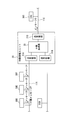
- the vehicle communication system 10 includes an electronic control unit (ECU) 30 (30A, 30B, 30C) connected to a plurality of buses 11 (11A, 11B, 11C), and the bus 11A. , 11B, based on a plurality of messages periodically received from the ECUs 30A, 30B, a relay connection unit 20 that periodically generates a new message and relays it to the ECU 30C connected to the bus 11C is provided.
- the communication protocol of the bus 11 is CAN (Control Area Network).
- the relay connection unit 20 includes a transmission / reception unit 21 (21A, 21B, 21C, and a relay processing unit 22.
- the transmission / reception units 21A, 21B, and 21C are connected to the buses 11A, 11B, and 11C, respectively, and transmit / receive messages from the buses 11A to 11C.
- the relay processing unit 22 is connected to each transmission / reception unit 21 and periodically transmits the parent message P to the ECUs 30A and 30B functioning as message transmitters connected to the buses 11A and 11B.
- the parent message P includes an ID part, the length of the data part is set to zero, and the priority of message transmission is set to be higher than that of the child message.
- the transmission timing of the parent message P is periodically transmitted using a timer.
- Child messages A and B are periodically received from the ECUs 30A and 30B, a new message C that is a synchronization message is generated based on the data of the child messages A and B, and relayed to the ECU 30C that functions as a message receiver. is doing.
- the ECU 30 ⁇ / b> A includes a transmission / reception unit 31 and a transmission timing calculation unit 32.
- the transmission / reception unit 31 and the transmission timing calculation unit 32 are shown in the ECU 30 ⁇ / b> A, but the ECU 30 ⁇ / b> B also includes the transmission / reception unit 31 and the transmission timing calculation unit 32.
- These ECUs 30A and 30B have a transmission / reception function, receive the parent message P from the relay connection unit 20, and transmit the child messages A and B based on the reception. In the present invention, the message transmission for transmitting the child message is performed. A machine.
- the ECU 30C connected to the bus 11C also includes the transmission / reception unit 31 and receives a new message from the relay connection unit 20, and is therefore a message receiver in the present invention. Since the ECU 30C does not transmit a child message in this embodiment, the ECU 30C does not include the transmission timing calculation unit 32 but includes a processing unit (not shown) for the message C received from the relay connection unit 20.
- the transmission / reception unit 31 of the ECU 30A (30B) performs the reception of the parent message P from the relay connection unit 20 and the transmission of the child message A transmitted by the own ECU 30A via the bus 11.
- the transmission timing calculation unit 32 transmits child messages periodically transmitted to the relay connection unit 20 in response to the parent message P with reference to the reception timing of the parent message P from the relay connection unit 20.
- the timing is set to gradually approach the reception timing of the parent message P. Only those other than the child messages are classified into several groups to define a parent-child relationship.
- the parent message defined here is called P ′.
- P ′ and the previous P that is, parents of different groups are gradually moved away from each other, and the child message is gradually brought closer to only its own parent.
- the ECU 30A and the ECU 30B gradually bring the transmission timings of the child messages A and B closer to the reception timing of the parent message P that the relay connection unit 20 periodically transmits to the ECU 30A and ECU 30B.
- the relay connection unit 20 periodically transmits the parent message P to the bus 11A and the bus 11B almost simultaneously.
- the transmission timing calculation unit 32 of the ECUs 30A and 30B adjusts the transmission timing of the child messages A and B so that the time difference r between the parent message P and the child messages A and B gradually decreases with time. .
- the relay processing unit 22 of the relay connection unit 20 generates a new message C based on the child messages A and B.
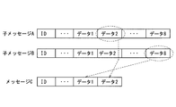
- FIG. 3 is an explanatory diagram of message generation.
- the message includes an ID part and a data part.
- the data 2 of the child message A and the data 8 of the child message B are taken out and newly used as the data portion of the message C.
- the relay processing unit 22 of the relay connection unit 20 performs generation processing of the message C after receiving the child message B, and after the generation time tp has elapsed since the reception of the child message B, the bus Message C is transmitted to 11C.
- the generation time tp is a time necessary for receiving the child messages A and B, generating the message C, and transmitting the message C.
- the message C1 is generated based on the child messages A1 and B1
- the message C2 is generated based on the child messages A2 and B2
- the message C3 is generated based on the child messages A3 and B3
- the message C is generated. It transmits to ECU30C.
- the message C created by the relay processing unit 22 of the relay connection unit 20 needs to be transmitted periodically at a predetermined transmission timing set in the ECU 30C.
- the relay connection unit 20 transmits a message C to the ECU 30C at times t1, t2, and t3.
- the relay processing unit 22 of the relay connection unit 20 receives the message B1.
- the time t1 is already the transmission timing of the message C1.
- the time when the message C1 can be generated is the time t1a after the generation time tp has elapsed since the message B1 was received. Therefore, the message C1 cannot be transmitted at the set transmission timing time t1.
- the message C1 is generated using the message B received once before, and the message C1 is transmitted at time t1.
- the messages A2, B2 and the messages A3, B3 are transmitted at a timing closer to the parent message P than the messages A1, B1, and the relay connection unit 20 has the set transmission timing.
- the messages C2 and C3 are generated by the time t2 and t3, and the messages C2 and C3 can be transmitted to the bus 11C at the set transmission timing.
- the ECU 30A, 30B gradually sets the transmission timing of the child message periodically transmitted to the relay connection unit 20 in response to the parent message P to the reception timing of the parent message P with reference to the reception timing of the parent message P. By approaching, the message C can be transmitted at the transmission timing set to the bus 11C.
- the parent message P is received with the transmission timing of messages other than the child message periodically transmitted to the relay connection unit 20 by the ECUs 30A and 30B and the timing of gradually moving away the child messages belonging to other groups from the parent message P.
- Child messages can be transmitted with priority over other child messages.
- the transmission interval Tnext becomes longer than To by setting force F> 0.
- the transmission timing of A approaches the transmission timing of the parent message P. That is, the time difference r between the parent message P and the child message A is shortened.
- the parent message P after the child message A means that the transmission timing of the parent message P is later than the child message A.
- the parent message P is earlier than the child message A.
- P means that the transmission timing is earlier than the child message A in time.
- the transmission interval Tnext is shorter than To by setting F ⁇ 0, so the transmission timing of the child message B Approaches the transmission timing of the parent message P. That is, the time difference r between the parent message P and the child message B is shortened. In this way, a state in which another message approaches one message is expressed as “attraction works”. That is, the child message is attracted to the parent message P.
- the transmission timing calculation unit 32 of the ECU 30A adjusts the transmission interval of messages X other than the child messages so that the transmission timing is separated from the parent message P.
- To be the most recent transmission interval of the message X.
- the transmission interval Tnext is shorter than To, so the transmission timing of the message X is Away from the transmission timing of the parent message P. That is, the time difference r between the message X and the parent message P becomes longer.
- the transmission interval Tnext becomes longer than To by setting F> 0, so the transmission timing of the message X Is away from the transmission timing of the parent message P. That is, the time difference r between the message X other than the child message and the parent message P becomes longer.
- a state in which another message leaves one message is expressed as “repulsive force works”. That is, a repulsive force acts on the message X with respect to the parent message P.
- the message X has the parent message P in both the front and back, but the time difference r between the message X and the parent message P is selected to be closer.
- FIG. 5 describes a case where the message X and the parent message P are not so far apart. For this reason, the message X other than the child message and the parent message P are gradually separated from each other and finally stabilized at about r ⁇ To / 2.
- the time difference when the parent message P is transmitted later in time than the child message is defined as the time difference in the positive direction.
- the force F is positive when the time difference r is positive and the force F is negative when the time difference r is negative, the force F is an attractive force, and the force F is negative and the time difference r is negative when the time difference r is positive. If the force F is positive when negative, F becomes a repulsive force.
- the force is expressed as F (r) as a function of the time difference r.
- of the time difference r. When the time difference r is ⁇ ⁇ (infinite in the positive or negative direction), the force F ( ⁇ ⁇ ) 0.
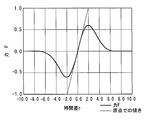
- FIG. 6 is an explanatory diagram showing an example of the relationship between the time difference r and the force F.
- FIG. 8 shows the operation when the parent message P is transmitted after the child message A.
- the ECU 30A receives the parent message P transmitted from the relay connection unit 20.
- the transmission timing calculation unit 32 determines whether or not the received message is the parent message P based on the ID (identifier) described in the parent message P.
- the ECU 30 ⁇ / b> A transmits the child message A via the transmission / reception unit 21.
- the ECU 30A receives the next parent message P.
- step S4 the transmission timing calculator 32 calculates a time difference r from the timing at which the child message A is transmitted and the timing at which the parent message P is received.
- the time difference r employs the smaller one of the time difference obtained from the reception timing of the parent message P observed in step S1 and the time difference obtained from the reception timing from the parent message P observed in step S3.
- step S5 the transmission timing calculator 32 calculates the force F using the time difference r.
- step S6 the transmission timing calculation unit 32 calculates the next transmission interval Tnext.
- the next child message A is transmitted after the transmission interval Tnext from the transmission timing of the child message A in the previous step S2.
- the operation of the ECU 30B transmitting the child message is the same.
- the relay connection unit 20 when the relay connection unit 20 transmits the parent message P to each bus 11 simultaneously, the message transmitter that has received the parent message P gradually sets the timing of transmitting the child message to the reception timing of the parent message P.
- the message X other than the child message child of the other group and the child message is gradually moved away.
- the message transmitter connected to each bus 11 transmits the child message almost simultaneously, and the timing at which the relay connection unit 20 receives the child message is almost the same. Therefore, the relay connection unit 20 can always generate a new message based on the latest child message, and can prevent the timing of transmitting a new message to the bus 11C from being delayed.
- FIG. 9 shows a second embodiment of the present invention.
- the message transmitter is a sensor or a switch. That is, the relay connection unit 20 relays the bus 11C to which the sensors 50A and 50B with communication function connected to the buses 11A and 11B and the ECU 50C with actuator function are connected. Based on a plurality of child messages A and B periodically received from the sensors 50A and 50B via the buses 11A and 11B, the relay connection unit 20 periodically generates a new message C and is connected to the bus 11C. Relay to ECU 50C with actuator function.
- the child messages A and B transmitted by the sensors 50A and 50B include data measured by the sensor 50.
- the sensor 50 is, for example, a front / rear wheel rotational speed sensor, a door opening / closing switch, or the like.
- the transmission timing of the parent message P transmitted from the relay connection unit 20 is not set by the timer of the first embodiment, but is triggered by the message M received from the bus 11C. That is, the relay connection unit 20 transmits the parent message P to the buses 11A and 11B, triggered by a message transmitted from the ECU 50C connected to the bus 11C to the relay connection unit 20 or another message M received from the bus 11C. ing.
- the message M is a message having a transmission cycle that matches or is a divisor with the transmission cycle of the parent message P transmitted from the relay connection unit 20.
- the relay connection unit 20 transmits the parent message P to the buses 11A and 11B, and the sensors 50A and 50B gradually bring the transmission timing of the child messages A and B closer to the reception timing of the parent message P. Therefore, the relay connection unit 20 can always generate a new message C based on the latest child message and transmit it to the ECU 50C with an actuator function.
- symbol is attached
- FIG. 10 shows a third embodiment of the present invention.
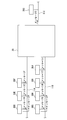
- a plurality of ECUs 30D to 30F are connected to one bus 11A connected to the relay connection unit 20, and the relay connection unit 20 is connected to 1 based on the child messages D, E, and F received from these ECUs 30D to 30F, respectively.
- Two new messages C are created, and the message C is transmitted to the ECU 30C serving as a message receiver via the bus 11C.
- a message having a small CAN ID, a high communication priority, and a short transmission cycle is set as a parent message P to the other ECUs 30E and 30F. That is, in the third embodiment, a message transmitter (a plurality of transmission / reception functions for transmitting a child message to the relay connection unit 20 while transmitting the child message to the relay connection unit 20 while not transmitting the parent message P from the relay connection unit 20).
- the ECU 30D is selected from among the ECUs 30D to 30F) as the transmission source of the parent message P.
- the relay connection unit 20 When other ECUs 30E and 30F receive the parent message P from the ECU 30D, transmission timing calculation provided in the ECUs 30E and 30F so that the child messages E and F transmitted from the ECUs 30E and 30F to the relay connection unit 20 gradually approach the message D.
- the child messages D, E, and F received by the relay connection unit 20 are substantially synchronized.
- the relay connection unit 20 always generates a new message C based on the latest child messages D, E, and F, and has an actuator function via the bus 11C. It can be transmitted to the ECU 50C. Since other configurations are the same as those of the first embodiment, the same reference numerals are given and description thereof is omitted.
- the parent message is transmitted from the ECU 30D to the other ECUs 30E, 30F.
- the CANID is small as described above. Since the message P having a high communication priority and a short transmission cycle is used as the parent message, if the message P is transmitted from the ECU 30E, the ECU 30E becomes the transmission source of the parent message.
- the parent message P is preferably the greatest common divisor of the transmission cycle of child messages transmitted from other ECUs to the relay connection unit 20. Or it is preferable that the transmission period of each child message is an integer (N) times of the parent message. However, N may be 1.
- FIG. 11 shows a modification of the third embodiment.
- a plurality of ECUs 30G to 30J are also connected to the other bus 11B connected to the relay connection unit 20, and the relay connection unit 20 is connected based on the child messages G to J received from these ECUs 30G to 30J.
- the new message C is generated, the child message G transmitted from the ECU 30G to the relay connection unit 20 is used as the parent message P transmitted to the other ECUs 30H, 30I, and 30J.
- Other configurations are the same as those of the third embodiment, and a description thereof will be omitted.
- a plurality of message transmitters are connected to the buses 11A and 11B connected to the relay connection unit 20 and other buses, respectively, and new messages are received by child messages received from the message transmitters connected to these one buses.
- the parent message is transmitted from the ECU connected to the bus for each bus.
- FIG. 12 shows a fourth embodiment.
- the fourth embodiment includes the first embodiment and the third embodiment, and the buses 11A and 11B connected to the relay connection unit 20 are the plurality of buses 11A and 11B as in the first embodiment.
- the relay connection unit 20 creates a new message C1 based on the child messages A and B received from the ECUs 30A and 30B connected to the ECU 30A, so that the parent message P is sent from the relay connection unit 20 to the ECU 30A via the buses 11A and 11B. , 30B.
- the relay connection unit 20 is connected to a bus 11D having a plurality of ECUs 30D to 30F as described in the third embodiment, and receives child messages D, E, F received from the plurality of ECUs 30D to 30F.
- the relay connection unit 20 Based on the above, the relay connection unit 20 generates a new message C2.
- the parent message P is not transmitted from the relay connection unit 20 to the bus 11D, and the message transmitted from the ECU 30D to the relay connection unit 20 is a parent message to the ECUs 30E and 30F.
- New messages C1 and C2 generated by the relay connection unit 20 are transmitted to the ECU 30C via the bus 11C.
- the relay connection unit 20 determines the transmission timing of the parent message of the message C2 transmitted from the relay connection unit 20 according to the priority of the messages C1 and C2. It is adjusted.
- the new message C2 may be transmitted to a message receiver on another bus.
- the parent message to be transmitted to the bus 11A is Pa
- the parent message to be transmitted to the bus 11B is Pb
- the parent message to be received from the bus 11D is Pd
- Pa and Pb can be repulsive to the parent message Pd.
- the intervals between the parent messages can be taken, the processing load in the relay connection unit 20 can be leveled, and the delay of the relay processing can be prevented.
- the timing of each child message is controlled so as to exert an attractive force on each parent message.
Landscapes
- Engineering & Computer Science (AREA)
- Computer Networks & Wireless Communication (AREA)
- Signal Processing (AREA)
- Small-Scale Networks (AREA)
Abstract
Description
Network)が標準となりつつある。CANプロトコルは、バスが開放状態の場合はどのECUもメッセージを送信することが可能な非同期通信である。
また、1つのバスに複数のメッセージ送信機が接続されている場合、これら複数のメッセージ送信機から1つのバスを介して周期的にメッセージを受信し、中継接続ユニットで新たなメッセージを生成する場合もある。
このように、複数のバスから、あるいは/および1つのバスから、複数のメッセージを中継接続ユニットは受信し、これら複数のメッセージに基づいて、複数の新たなメッセージを生成し、該新たなメッセージを他のバスのメッセージ受信機に送信している。即ち、各新たなメッセージを生成するための複数のメッセージ・グループが、複数存在する場合が多い。
前記のようにCAN通信でメッセージを送受信する場合、メッセージ送信機となるECUやセンサは接続したバスが開放状態であればメッセージを送信することができるため、中継接続ユニットが各メッセージ送信機からバスを介して送信されたメッセージを受信するタイミングがメッセージ送信機間で同期しない場合が多い。
また、新たなメッセージを送信するタイミングの周期を守る場合には、受信が遅れているメッセージに替えて、1回前に受信したメッセージを用いて新たなメッセージを生成しなければならないという問題がある。
メッセージ送信機と接続した1以上のバスと、メッセージ受信機と接続したバスとを中継する中継接続ユニットを備え、
前記中継接続ユニットはメッセージ送信機から受信する複数のメッセージに基づいて新たなメッセージを生成し、該生成したメッセージを前記メッセージ受信機にバスを介して送信しており、
前記新たに生成するメッセージは1以上であり、複数の新たなメッセージは該各メッセージを生成するメッセージをグループ分けし、
前記中継接続ユニットが前記メッセージ送信機から受信する1つの新たなメッセージを生成する同じグループの複数のメッセージは送信タイミングを漸次近づけていることを特徴とする車両通信システムを提供している。
前記中継接続ユニットは、前記バスと接続した送受信部と、前記複数のメッセージ送信機から受信する複数のメッセージに基づいて新たなメッセージを生成する中継処理部を備え、
前記中継接続ユニットへ前記新たなメッセージの生成用とする子メッセージの送信を要求する親メッセージを、前記中継接続ユニットから前記子メッセージを送信するメッセージ送信機に送信し、または、前記1つのバスに接続されている前記複数のメッセージ送信機のうちの1つのメッセージ送信機から他のメッセージ送信機へ前記親メッセージを送信し、
前記子メッセージを送信するメッセージ送信機は、前記親メッセージの受信タイミングを基準として、該親メッセージに応答して周期的に中継接続ユニットへ送信する前記子メッセージの送信タイミングを前記親メッセージの受信タイミングに漸次近づけると共に、他のグループの親メッセージの子メッセージおよび該子メッセージ以外の送信メッセージの送信タイミングは前記親メッセージの受信タイミングに漸次遠ざけるタイミングとする送信タイミング演算部を備えている。
前記子メッセージを中継接続ユニットに送信する複数のメッセージ送信機が1つのバスと接続されている場合は、該1つのバスに接続されている複数のメッセージ送信機のうちの1つのメッセージ送信機から他のメッセージ送信機へ親メッセージを送信してもよい。 かつ、この場合も親メッセージを中継接続ユニットから送信しても良い。
中継接続ユニットで生成された新たなメッセージを受信する前記メッセージ受信機は、電子制御ユニットやアクチュエータからなる。
従って、中継接続ユニットは常に最新の子メッセージに基づいて新たなメッセージを生成することができると共に、該新たなメッセージをメッセージ受信機へ周期的に送信でき、送信タイミングが遅延することを防ぐことができる。
かつ、該中継接続ユニットから送信する親メッセージは、フレームデータが短い又はフレームデータが無いメッセージとすることが好ましい。
親メッセージは子メッセージの送信を要求するだけのメッセージであるため、バス負荷率を低減するために、メッセージのデータ長さを極力短くし、あるいはデータ無し(DLC=0)とすることが好ましい。
このように、親メッセージとするメッセージはIDが小さいものとすると、通信の優先度が高くなり、子メッセージを他のメッセージより優先して中継接続ユニットに送信することができる。かつ、送信周期が短周期のメッセージとすると、他の複数のメッセージ送信機から中継接続ユニットへ送信する子メッセージを送信周期の最大公約数、または、子メッセージの送信周期を親メッセージの送信周期の整数(N)倍とすることができる。
11(11A、11B、11C) バス
20 中継接続ユニット
22 中継処理部
30(30A~30J) 電子制御ユニット(ECU)
32 送信タイミング演算部
50A、50B 通信機能付きセンサ
50C アクチュエータ機能付きECU
P 親メッセージ
A、B 子メッセージ
C 新たなメッセージ
X 他のグループの親もしくは子メッセージおよびそれ以外のメッセージ
図1乃至図9に本発明の第1実施形態を示す。
本発明の車両通信システム10は、複数のバス11(11A、11B、11C)に接続された電子制御ユニット(ECU)30(30A、30B、30C)と、該バス11間に介在され、バス11A、11Bを介してECU30A、30Bから周期的に受信する複数のメッセージを基に、新たなメッセージを周期的に生成してバス11Cに接続されたECU30Cに中継する中継接続ユニット20を備えている。前記バス11の通信プロトコルはCAN(Control Area Network)である。
送受信部21A、21B、21Cはバス11A、11B、11Cとそれぞれ接続し、各バス11A~11Cからのメッセージの送受信を行っている。
中継処理部22は各送受信部21と接続し、バス11A、11Bに接続したメッセージ送信機として機能するECU30A、30Bに周期的に親メッセージPを送信している。親メッセージPはID部を備えているが、データ部の長さをゼロとし、メッセージ送信の優先度を子メッセージと比べて高くなるように設定している。
前記親メッセージPの送信タイミングは、本実施形態ではタイマを用いて周期的に送信している。
また、ECU30A、30Bから子メッセージA、Bを周期的に受信し、該子メッセージA、Bのデータに基づいて同期メッセージである新たなメッセージCを生成し、メッセージ受信機として機能するECU30Cに中継している。
これらECU30Aと30Bは送受信機能を備え、中継接続ユニット20から親メッセージPを受信し、該受信に基づいて子メッセージA、Bを送信するものであるが、本発明では子メッセージを送信するメッセージ送信機としている。
バス11Cに接続したECU30Cも送受信部31を備え、中継接続ユニット20から新たなメッセージを受信するものであるため、本発明ではメッセージ受信機としている。該ECU30Cは本実施形態では子メッセージを送信していないので、送信タイミング演算部32は備えておらず、中継接続ユニット20から受信したメッセージCの処理部(図示せず)を備えている。
送信タイミング演算部32は、詳細は後述するが、中継接続ユニット20からの親メッセージPの受信タイミングを基準として、親メッセージPに応答して周期的に中継接続ユニット20へ送信する子メッセージの送信タイミングを、親メッセージPの受信タイミングに漸次近づける設定としている。
前記子メッセージ以外のものだけを対象に、幾つかのグループに分類して、親子関係を定義する。ここで定義した親メッセージをP’と呼ぶ。P’と先のP、即ち、異なるグループの親同士は漸次遠ざけ、子メッセージは自分の親にだけに漸次近づけている。
前記のように、ECU30A、ECU30Bは、中継接続ユニット20が周期的にECU30A、ECU30Bに送信する親メッセージPの受信タイミングに、子メッセージA、Bの送信タイミングを漸次近づけている。
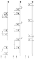
図2(A)、(B)に示すように、中継接続ユニット20はバス11A、バス11Bにほぼ同時に親メッセージPを周期的に送信している。このとき、ECU30A、30Bの送信タイミング演算部32は、子メッセージA、Bの送信タイミングを調整し、親メッセージPと子メッセージA、Bの時間差rが時間の経過と共に漸次短くなるようにしている。
即ち、生成時間tpは子メッセージAとBとを受信してメッセージCを生成し、メッセージCを送信するまでに必要な時間となる。
このように、子メッセージA1、B1を基にメッセージC1を生成し、子メッセージA2、B2を基にメッセージC2を生成し、子メッセージA3、B3を基にメッセージC3を生成し、該メッセージCをECU30Cに送信している。
前記図2(C)に示すように、中継接続ユニット20は時刻t1、t2、t3のタイミングでメッセージCをECU30Cに送信している。
しかし、ECU30A、30BからメッセージA1、B1が図2(A)(B)のように親メッセージPから離れたタイミングで送信される場合、中継接続ユニット20の中継処理部22がメッセージB1の受信を完了する前に既にメッセージC1の送信タイミングである時刻t1となっている。
このため、メッセージC1が生成できる時刻はメッセージB1を受信してから生成時間tp経過後の時刻t1aになる。よって、設定した送信タイミングの時刻t1でメッセージC1を送信できない。または、1回前に受信したメッセージBを用いてメッセージC1を生成し、時刻t1でメッセージC1を送信することになる。
このように、ECU30A、30Bが親メッセージPの受信タイミングを基準として、親メッセージPに応答して周期的に中継接続ユニット20へ送信する子メッセージの送信タイミングを、親メッセージPの受信タイミングに漸次近づけることにより、メッセージCのバス11Cへ設定した送信タイミングで送信できる。
親メッセージPに対して、ECU30Aが子メッセージAの送信タイミングを調整する例について説明するが、ECU30Bが子メッセージBの送信タイミングを調整する場合も同様である。
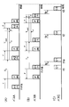
1つ前の親メッセージPと子メッセージAを比べると、図4(A)では1つ前の親メッセージPが子メッセージAよりも先となるが、1つ前の親メッセージPと子メッセージAの時間差と、一つ後の親メッセージPと子メッセージAの時間差とを比較して、短いほうを送信タイミング演算部32が用いる時間差rとして採用する。図4(B)の場合も同様である。
このように、あるメッセージに他のメッセージが近づいていく状態を、「引力が働く」と表現する。即ち、子メッセージは親メッセージPに対して引力が働いている。
ECU30Aの送信タイミング演算部32は親メッセージPと送信タイミングが離れるように子メッセージ以外のメッセージXの送信間隔を調整する。該メッセージXの直近の送信間隔をToとする。
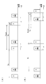
図5(A)に示すように、メッセージXよりも親メッセージPのほうが後に送信されている場合、F<0とすることで、送信間隔TnextはToより短くなるので、メッセージXの送信タイミングは親メッセージPの送信タイミングから離れる。即ち、メッセージXと親メッセージPとの時間差rは長くなる。
このように、あるメッセージに他のメッセージが離れていく状態を、「斥力が働く」と表現する。即ち、親メッセージPに対してメッセージXには斥力が働いている。
なお、実際にはメッセージXは前と後ろの両方に親メッセージPがあるが、メッセージXと親メッセージPとの時間差rは近い方を選ぶ。例えば図5ではメッセージXと親メッセージPとがそれほど離れていない場合を述べているが、大きく離れた場合には時間差rは近い方を選ぶ。このために子メッセージ以外のメッセージXと親メッセージPは徐々に離れて行き、最終的にはほぼr≒To/2のところで安定する。
各メッセージは、直近の送信間隔Toに対して、次の送信間隔TnextをTnext=To+Fと定める。即ち、力Fによって送信間隔を微調整する。
このとき、時間差rが正のときに力Fが正、時間差rが負のときに力Fが負ならば、力Fは引力となり、時間差rが正のときに力Fが負、時間差rが負のときに力Fが正ならば、Fは斥力となる。
力Fが引力の場合、r=0の近傍では、r>0ならばF>0、r<0ならばF<0である。力Fが斥力の場合は、r>0ならばF<0、r<0ならばF>0である。時間差rの絶対値|r|が十分に大きいときには、力Fの絶対値|F|は時間差rの絶対値|r|に対して減衰する。
時間差rが±∞(正方向又は負方向に無限大)であるときには、力F(±∞)=0となる。
子メッセージは、親メッセージPに対して引力又は斥力が働くように設定する。
図6は、時間差rと力Fとの関係を示した例を示す説明図である。図6は、力F(r)はF(r)=2・G・r/(r2+g2)とし、G=1、g=2とした場合である。
このとき、前述したように、時間差rが0のときは力F(0)=0となり、力Fが引力の場合、r=0の近傍では、r>0ならばF>0、r<0ならばF<0となる。時間差rの絶対値|r|が十分に大きいときには、力Fの絶対値|F|は時間差rの絶対値|r|に比例して減衰する。時間差rが±∞であるときには、力F(±∞)=0となる。
また、図7は、力F=G・(r/g2)・exp(-r2/(2・g2))とし、G=2、g=2とした場合である。
なお、各ECU30の送信タイミング演算部32は、子メッセージを周期的にバス11に送信しており、送信周期Toを算出している。また、図8は親メッセージPが子メッセージAよりも後に送信されている場合の動作である。
ステップS1では、ECU30Aは中継接続ユニット20が送信した親メッセージPを受信している。なお、送信タイミング演算部32は、親メッセージPに記載されたID(識別子)により、受信したメッセージが親メッセージPか否かを判断している。
ステップS2では、ECU30Aは送受信部21を介して子メッセージAを送信している。
ステップS3では、ECU30Aは次の親メッセージPを受信している。
ステップS5では、送信タイミング演算部32は、時間差rを用いて力Fを算出している。
ステップS1に戻り、前回のステップS2の子メッセージAの送信タイミングから送信間隔Tnext後に次の子メッセージAを送信している。
子メッセージを送信しているECU30Bの動作も同様である。
従って、中継接続ユニット20は、常に最新の子メッセージに基づいて新たなメッセージを生成することができると共に、バス11Cに新たなメッセージを送信するタイミングが遅延することを防ぐことができる。
第2実施形態の車両通信システム10では、メッセージ送信機はセンサまたはスイッチとしている。即ち、バス11A、11Bに接続された通信機能付きセンサ50A、50Bと、アクチュエータ機能付きECU50Cが接続されたバス11Cを中継接続ユニット20で中継している。バス11A、11Bを介してセンサ50A、50Bから周期的に受信する複数の子メッセージA、Bを基に、中継接続ユニット20は新たなメッセージCを周期的に生成してバス11Cに接続されたアクチュエータ機能付きECU50Cに中継している。
センサ50A、50Bが送信する子メッセージA、Bには、当該センサ50が測定したデータが含まれている。センサ50は、例えば前後輪回転数センサ、ドア開閉スイッチ等である。
なお、他の構成および作用効果は第1実施形態と同様のため、同一の符号を付して説明を省略する。
第3実施形態では中継接続ユニット20に接続する1つのバス11Aに複数のECU30D~30Fが接続され、中継接続ユニット20はこれらECU30D~30Fからそれぞれ受信する子メッセージD、E、Fに基づいて1つの新たなメッセージCを作成して、バス11Cを介してメッセージ受信機となるECU30CにメッセージCを送信している。
即ち、第3実施形態では親メッセージPを中継接続ユニット20から送信せず、1つのバス11Aに接続していると共に子メッセージを中継接続ユニット20へ送信する複数の送受信機能を有するメッセージ送信機(ECU30D~30F)のうちから選択して、ECU30Dを親メッセージPの送信元としている。
他の構成は前記第1実施形態と同様であるため、同一符号を付して説明を省略する。
該親メッセージPは、他のECUからの中継接続ユニット20へ送信する子メッセージの送信周期の最大公約数となっていることが好ましい。または、各子メッセージの送信周期は親メッセージの整数(N)倍であることが好ましい。但し、Nは1であってもよい。
第3実施形態と同様に、中継接続ユニット20に接続した他のバス11Bにも複数のECU30G~30Jが接続され、これらECU30G~30Jから受信する子メッセージG~Jに基づいて中継接続ユニット20が新たなメッセージCを生成する場合、ECU30Gから中継接続ユニット20に送信する子メッセージGを、他のECU30H、30I、30Jへ送信する親メッセージPとしている。
他の構成は第3実施形態と同様であり、説明を省略する。
このように、中継接続ユニット20と接続するバス11A、11B、さらに他のバスにそれぞれ複数のメッセージ送信機が接続され、これら1つのバスに接続されたメッセージ送信機から受信する子メッセージで新たなメッセージCを生成する場合、各バス毎に、該バスに接続されたECUから親メッセージを送信している。
第4実施形態は第1実施形態と第3実施形態とを含むものであり、中継接続ユニット20に接続されるバス11Aと11Bとは第1実施形態と同様に、これら複数のバス11Aと11Bとに接続されたECU30A、30Bから受信する子メッセージA、Bに基づいて中継接続ユニット20が新たなメッセージC1を作成するため、親メッセージPは中継接続ユニット20からバス11A、11Bを介してECU30A、30Bに送信している。
さらに、中継接続ユニット20には、前記第3実施形態に記載のような、複数のECU30D~30Fを備えたバス11Dと接続され、これら複数のECU30D~30Fから受信する子メッセージD、E、Fに基づいて中継接続ユニット20が新たなメッセージC2を生成する。該バス11Dには中継接続ユニット20から親メッセージPは送信せず、ECU30Dから中継接続ユニット20へ送信するメッセージをECU30E、30Fへの親メッセージとしている。
なお、新たなメッセージC2は他のバスのメッセージ受信機へ送信してもよい。
この場合、バス11Aに送信する親メッセージをPa、バス11Bに送信する親メッセージをPb、バス11Dから受信する親メッセージをPdとすれば、Pa、Pbを親メッセージPdに対して斥力を働かせる事により、親メッセージ同士の間隔を取る事が出来、中継接続ユニット20での処理負荷を平準化して中継処理の遅延を防ぐ事が出来る。この時、各子メッセージは、それぞれの親メッセージに対し引力を働かせるようにタイミングを制御する。
Claims (9)
- メッセージ送信機と接続した1以上のバスと、メッセージ受信機と接続したバスとを中継する中継接続ユニットを備え、
前記中継接続ユニットはメッセージ送信機から受信する複数のメッセージに基づいて新たなメッセージを生成し、該生成したメッセージを前記メッセージ受信機にバスを介して送信しており、
前記新たに生成するメッセージは1以上であり、複数の新たなメッセージは該各メッセージを生成するメッセージをグループ分けし、
前記中継接続ユニットが前記メッセージ送信機から受信する1つの新たなメッセージを生成する同じグループの複数のメッセージは送信タイミングを漸次近づけていることを特徴とする車両通信システム。 - 前記中継接続ユニットが受信するメッセージは、前記新たな1つのメッセージを生成する複数のメッセージ以外のメッセージおよび他のグループのメッセージの受信タイミングを漸次遠ざけている請求項1に記載の車両通信システム。
- 前記グループ毎に親メッセージと子メッセージを設定し、子メッセージは、同じグループの親メッセージに漸次近づけるように送信タイミングを制御し、異なる群に属する親メッセージ同士は漸次遠ざけるように送信タイミングを制御している請求項1に記載の車両通信システム。
- 前記中継接続ユニットは、メッセージ送信機をそれぞれ接続した複数のバスあるいは/および複数のメッセージ送信機を接続した1つのバスと接続され、
前記中継接続ユニットは、前記バスと接続した送受信部と、前記複数のメッセージ送信機から受信する複数のメッセージに基づいて新たなメッセージを生成する中継処理部を備え、
前記中継接続ユニットへ前記新たなメッセージの生成用とする子メッセージの送信を要求する親メッセージを、前記中継接続ユニットから前記子メッセージを送信するメッセージ送信機に送信し、または、前記1つのバスに接続されている前記複数のメッセージ送信機のうちの1つのメッセージ送信機から他のメッセージ送信機へ前記親メッセージを送信し、
前記子メッセージを送信するメッセージ送信機は、前記親メッセージの受信タイミングを基準として、該親メッセージに応答して周期的に中継接続ユニットへ送信する前記子メッセージの送信タイミングを前記親メッセージの受信タイミングに漸次近づける送信タイミング演算部を備えている請求項1乃至請求項3のいずれか1項に記載の車両通信システム。 - 前記メッセージ送信機は電子制御ユニット、アクチュエータあるいは/およびセンサであり、前記メッセージ受信機は電子制御ユニットあるいはアクチュエータである請求項1乃至請求項4のいずれか1項に記載の車両通信システム。
- 前記中継接続ユニットから前記親メッセージを、前記複数のバスにそれぞれ接続したメッセージ送信機あるいは/および複数のメッセージ送信機を接続したバスの各メッセージ送信機へ送信している請求項3乃至請求項5のいずれか1項に記載の車両通信システム。
- 前記中継接続ユニットから送信する親メッセージの送信タイミングは、該中継接続ユニットに設けたタイマにより設定し、または前記メッセージ受信機と接続したバスから周期的に受信するメッセージの受信をトリガとして設定している請求項6に記載の車両用通信システム。
- 前記中継接続ユニットから送信する親メッセージは、CANIDが小さく通信優先度が高いメッセージとし、または/および、フレームデータが短い又はフレームデータが無いメッセージとしている請求項6または請求項7に記載の車両用通信システム。
- 前記中継接続ユニットは、1つのバスに接続された複数のメッセージ送信機から受信する複数の子メッセージに基づいて新たなメッセージを生成しており、
前記複数のメッセージ送信機のうちの1つのメッセージ送信機から他のメッセージ送信機に親メッセージを送信し、該メッセージ送信機から送信する親メッセージとするメッセージは、CANIDが小さく優先度が高く且つ送信周期が短周期のメッセージである請求項3乃至請求項8のいずれか1項に記載の車両用通信システム。
Priority Applications (3)
| Application Number | Priority Date | Filing Date | Title |
|---|---|---|---|
| DE112009000691.4T DE112009000691B8 (de) | 2008-04-02 | 2009-03-31 | Fahrzeugkommunikationssystem |
| JP2010505943A JP5006443B2 (ja) | 2008-04-02 | 2009-03-31 | 車両通信システム |
| US12/934,777 US8874813B2 (en) | 2008-04-02 | 2009-03-31 | Vehicle communication system |
Applications Claiming Priority (2)
| Application Number | Priority Date | Filing Date | Title |
|---|---|---|---|
| JP2008-096599 | 2008-04-02 | ||
| JP2008096599 | 2008-04-02 |
Publications (1)
| Publication Number | Publication Date |
|---|---|
| WO2009123201A1 true WO2009123201A1 (ja) | 2009-10-08 |
Family
ID=41135570
Family Applications (1)
| Application Number | Title | Priority Date | Filing Date |
|---|---|---|---|
| PCT/JP2009/056687 Ceased WO2009123201A1 (ja) | 2008-04-02 | 2009-03-31 | 車両通信システム |
Country Status (4)
| Country | Link |
|---|---|
| US (1) | US8874813B2 (ja) |
| JP (1) | JP5006443B2 (ja) |
| DE (1) | DE112009000691B8 (ja) |
| WO (1) | WO2009123201A1 (ja) |
Cited By (2)
| Publication number | Priority date | Publication date | Assignee | Title |
|---|---|---|---|---|
| JP2010247791A (ja) * | 2009-04-20 | 2010-11-04 | Autonetworks Technologies Ltd | 入出力装置及び制御システム |
| US10129124B2 (en) | 2015-12-10 | 2018-11-13 | Hyundai Motor Company | Method and apparatus for controlling in-vehicle mass diagnostic communication |
Families Citing this family (8)
| Publication number | Priority date | Publication date | Assignee | Title |
|---|---|---|---|---|
| JP5651442B2 (ja) * | 2010-11-29 | 2015-01-14 | 矢崎総業株式会社 | 動作支援装置、電子機器、電子制御装置、及び、制御システム |
| US9773354B2 (en) | 2014-12-11 | 2017-09-26 | Hyundai Motor Company | Terminal mounted in vehicle, control method thereof, data center and control method thereof |
| JP6631415B2 (ja) * | 2016-06-15 | 2020-01-15 | 株式会社デンソー | 中継装置 |
| CN105988404B (zh) * | 2016-06-30 | 2018-12-04 | 深圳市优必选科技有限公司 | 一种伺服器控制系统 |
| JP7059899B2 (ja) | 2018-11-09 | 2022-04-26 | トヨタ自動車株式会社 | ネットワークシステム |
| US11381421B2 (en) * | 2020-09-17 | 2022-07-05 | Ford Global Technologies, Llc | Using signal rating to identify security critical CAN messages and nodes for efficient implementation of distributed network security features |
| US11539714B2 (en) | 2020-09-17 | 2022-12-27 | Ford Global Technologies, Llc | Assigning categories for messages and symmetric key per category to localize the impact in case of key compromise |
| US12160326B2 (en) * | 2021-10-07 | 2024-12-03 | Ford Global Technologies, Llc | Dynamic controller area network messaging |
Citations (3)
| Publication number | Priority date | Publication date | Assignee | Title |
|---|---|---|---|---|
| JP2005328119A (ja) * | 2004-05-12 | 2005-11-24 | Nec Electronics Corp | 通信メッセージ変換装置、通信方法及び通信システム |
| JP2007129467A (ja) * | 2005-11-02 | 2007-05-24 | Auto Network Gijutsu Kenkyusho:Kk | 中継接続ユニット |
| JP2007174180A (ja) * | 2005-12-21 | 2007-07-05 | Nissan Motor Co Ltd | ゲートウェイ装置およびデータ送受信制御方法 |
Family Cites Families (17)
| Publication number | Priority date | Publication date | Assignee | Title |
|---|---|---|---|---|
| JP3578058B2 (ja) * | 2000-07-13 | 2004-10-20 | 株式会社デンソー | 多重通信システム |
| SE524201C2 (sv) * | 2002-12-17 | 2004-07-06 | Lars-Berno Fredriksson | Anordning vid distribuerat styr- och övervakningssystem |
| JP2007514346A (ja) * | 2003-11-19 | 2007-05-31 | ハネウェル・インターナショナル・インコーポレーテッド | 非同期ハブ |
| JP4483694B2 (ja) * | 2004-06-22 | 2010-06-16 | 株式会社デンソー | 車両用通信システム |
| JP2006020038A (ja) * | 2004-07-01 | 2006-01-19 | Denso Corp | 物理量センサ装置およびその検査装置 |
| AT501480B8 (de) * | 2004-09-15 | 2007-02-15 | Tttech Computertechnik Ag | Verfahren zum erstellen von kommunikationsplänen für ein verteiltes echtzeit-computersystem |
| JP2006180205A (ja) * | 2004-12-22 | 2006-07-06 | Denso Corp | 車載送信装置およびプログラム。 |
| US7548551B2 (en) * | 2005-08-19 | 2009-06-16 | Gm Global Technology Operations, Inc. | System and method of optimizing the bandwidth of a time triggered communication protocol with homogeneous slot sizes |
| JP4724095B2 (ja) * | 2006-11-21 | 2011-07-13 | 株式会社オートネットワーク技術研究所 | 中継接続ユニット及び車載用通信システム |
| JP4950704B2 (ja) * | 2007-03-06 | 2012-06-13 | 株式会社オートネットワーク技術研究所 | 車載用の中継接続ユニット |
| JP5022740B2 (ja) * | 2007-03-09 | 2012-09-12 | 矢崎総業株式会社 | 中継コネクタユニット、ワイヤハーネス組付体、及び、電子機器制御システム |
| US8626833B2 (en) | 2007-11-30 | 2014-01-07 | Autonetworks Technologies, Ltd. | Vehicle-mounted communication system |
| JP4917557B2 (ja) * | 2008-01-09 | 2012-04-18 | 株式会社オートネットワーク技術研究所 | 車載用の中継接続ユニット |
| DE112009000409B4 (de) * | 2008-02-26 | 2013-04-11 | Autonetworks Technologies, Ltd. | Weiterleitungs-Verbindungseinheit für ein Fahrzeug |
| DE102008049244A1 (de) * | 2008-09-26 | 2010-04-01 | Dspace Digital Signal Processing And Control Engineering Gmbh | Konfigurationseinrichtung zur Konfiguration eines zeitgesteuerten Bussystems |
| CN102204174A (zh) * | 2008-11-04 | 2011-09-28 | 株式会社自动网络技术研究所 | 通信装置、中继装置、通信系统及通信方法 |
| EP2509263B1 (en) * | 2009-12-02 | 2016-08-10 | Toyota Jidosha Kabushiki Kaisha | Data communication network system |
-
2009
- 2009-03-31 US US12/934,777 patent/US8874813B2/en not_active Expired - Fee Related
- 2009-03-31 JP JP2010505943A patent/JP5006443B2/ja not_active Expired - Fee Related
- 2009-03-31 WO PCT/JP2009/056687 patent/WO2009123201A1/ja not_active Ceased
- 2009-03-31 DE DE112009000691.4T patent/DE112009000691B8/de not_active Expired - Fee Related
Patent Citations (3)
| Publication number | Priority date | Publication date | Assignee | Title |
|---|---|---|---|---|
| JP2005328119A (ja) * | 2004-05-12 | 2005-11-24 | Nec Electronics Corp | 通信メッセージ変換装置、通信方法及び通信システム |
| JP2007129467A (ja) * | 2005-11-02 | 2007-05-24 | Auto Network Gijutsu Kenkyusho:Kk | 中継接続ユニット |
| JP2007174180A (ja) * | 2005-12-21 | 2007-07-05 | Nissan Motor Co Ltd | ゲートウェイ装置およびデータ送受信制御方法 |
Cited By (2)
| Publication number | Priority date | Publication date | Assignee | Title |
|---|---|---|---|---|
| JP2010247791A (ja) * | 2009-04-20 | 2010-11-04 | Autonetworks Technologies Ltd | 入出力装置及び制御システム |
| US10129124B2 (en) | 2015-12-10 | 2018-11-13 | Hyundai Motor Company | Method and apparatus for controlling in-vehicle mass diagnostic communication |
Also Published As
| Publication number | Publication date |
|---|---|
| JP5006443B2 (ja) | 2012-08-22 |
| US20110035521A1 (en) | 2011-02-10 |
| US8874813B2 (en) | 2014-10-28 |
| DE112009000691T8 (de) | 2012-04-05 |
| DE112009000691T5 (de) | 2011-03-24 |
| DE112009000691B4 (de) | 2014-06-12 |
| DE112009000691B8 (de) | 2014-09-04 |
| JPWO2009123201A1 (ja) | 2011-07-28 |
Similar Documents
| Publication | Publication Date | Title |
|---|---|---|
| JP5006443B2 (ja) | 車両通信システム | |
| JP4824662B2 (ja) | 多数のバスのサイクルタイムを同期させる方法と装置及び対応するバスシステム | |
| JP4742169B2 (ja) | 車載用通信システム | |
| US20190207862A1 (en) | On-vehicle system, gateway, relay, non-transitory computer-readable medium storing program, information processing method, information processing system, and vehicle | |
| CN104272664B (zh) | 用于车辆的网关、节点和方法 | |
| US7310327B2 (en) | Method and apparatus for time synchronizing an in-vehicle network | |
| JP4617440B2 (ja) | データ通信システムまたはその方法 | |
| CN100417145C (zh) | 通过交换式数据网络传输数据的方法和系统 | |
| CN110679116B (zh) | 用于总线系统的用户站和用于改善对总线系统中的比特定时要求的遵守的方法 | |
| JP2011193227A (ja) | 通信ネットワークシステム、中継端末、マイクロコンピュータ、送受信装置 | |
| KR20090099534A (ko) | 통신 시스템 시동 방법, 통신 매체와 이에 접속된 복수의 가입자를 갖는 통신 시스템 및 이러한 통신 시스템의 가입자 | |
| JP4162093B2 (ja) | 通信システム | |
| KR102430076B1 (ko) | 차량 네트워크 시스템에서 시간 동기화 스위치 및 그것의 동작 방법 | |
| JP5107704B2 (ja) | バスシステムの制御方法、バスシステムの装置およびバスシステム | |
| CN115550095B (zh) | Lin通信电路以及在lin总线之间通信的方法 | |
| JP2015065546A (ja) | 車両制御装置 | |
| CN107070573A (zh) | 监测基于以太网的网络中的时钟同步状态 | |
| CN104285424A (zh) | 在面向包的通讯网络中传输数据的方法和通讯网络上的相应设置的用户设备 | |
| Min et al. | Interrupt-enabled physical layer collision avoidance for 10base-t1s automotive ethernet | |
| CN111247501B (zh) | 用于在两个物理接口之间传输数据的设备及方法 | |
| KR101714085B1 (ko) | 플렉스레이 통신을 이용한 차량용 통신스케줄 설정방법 | |
| JP7124681B2 (ja) | 中継装置 | |
| Gharavi et al. | Deterministic intra-vehicle communications: timing and synchronization | |
| KR101705005B1 (ko) | 차량 avb 환경에서 네트워크 관리 방법 | |
| CN107070575B (zh) | 基于以太网的网络中的时钟同步监测 |
Legal Events
| Date | Code | Title | Description |
|---|---|---|---|
| 121 | Ep: the epo has been informed by wipo that ep was designated in this application |
Ref document number: 09727096 Country of ref document: EP Kind code of ref document: A1 |
|
| WWE | Wipo information: entry into national phase |
Ref document number: 2010505943 Country of ref document: JP |
|
| WWE | Wipo information: entry into national phase |
Ref document number: 12934777 Country of ref document: US |
|
| WWE | Wipo information: entry into national phase |
Ref document number: 1120090006914 Country of ref document: DE |
|
| RET | De translation (de og part 6b) |
Ref document number: 112009000691 Country of ref document: DE Date of ref document: 20110324 Kind code of ref document: P |
|
| 122 | Ep: pct application non-entry in european phase |
Ref document number: 09727096 Country of ref document: EP Kind code of ref document: A1 |