WO2009119797A1 - 引き戸の閉扉阻止装置及び閉扉阻止装置を備える自動閉扉装置 - Google Patents
引き戸の閉扉阻止装置及び閉扉阻止装置を備える自動閉扉装置 Download PDFInfo
- Publication number
- WO2009119797A1 WO2009119797A1 PCT/JP2009/056272 JP2009056272W WO2009119797A1 WO 2009119797 A1 WO2009119797 A1 WO 2009119797A1 JP 2009056272 W JP2009056272 W JP 2009056272W WO 2009119797 A1 WO2009119797 A1 WO 2009119797A1
- Authority
- WO
- WIPO (PCT)
- Prior art keywords
- support
- sliding door
- closing
- rotating body
- engaging portion
- Prior art date
- Legal status (The legal status is an assumption and is not a legal conclusion. Google has not performed a legal analysis and makes no representation as to the accuracy of the status listed.)
- Ceased
Links
Images


Classifications
-
- E—FIXED CONSTRUCTIONS
- E05—LOCKS; KEYS; WINDOW OR DOOR FITTINGS; SAFES
- E05F—DEVICES FOR MOVING WINGS INTO OPEN OR CLOSED POSITION; CHECKS FOR WINGS; WING FITTINGS NOT OTHERWISE PROVIDED FOR, CONCERNED WITH THE FUNCTIONING OF THE WING
- E05F1/00—Closers or openers for wings, not otherwise provided for in this subclass
- E05F1/08—Closers or openers for wings, not otherwise provided for in this subclass spring-actuated, e.g. for horizontally sliding wings
- E05F1/16—Closers or openers for wings, not otherwise provided for in this subclass spring-actuated, e.g. for horizontally sliding wings for sliding wings
-
- E—FIXED CONSTRUCTIONS
- E05—LOCKS; KEYS; WINDOW OR DOOR FITTINGS; SAFES
- E05Y—INDEXING SCHEME ASSOCIATED WITH SUBCLASSES E05D AND E05F, RELATING TO CONSTRUCTION ELEMENTS, ELECTRIC CONTROL, POWER SUPPLY, POWER SIGNAL OR TRANSMISSION, USER INTERFACES, MOUNTING OR COUPLING, DETAILS, ACCESSORIES, AUXILIARY OPERATIONS NOT OTHERWISE PROVIDED FOR, APPLICATION THEREOF
- E05Y2201/00—Constructional elements; Accessories therefor
- E05Y2201/60—Suspension or transmission members; Accessories therefor
- E05Y2201/622—Suspension or transmission members elements
- E05Y2201/71—Toothed gearing
-
- E—FIXED CONSTRUCTIONS
- E05—LOCKS; KEYS; WINDOW OR DOOR FITTINGS; SAFES
- E05Y—INDEXING SCHEME ASSOCIATED WITH SUBCLASSES E05D AND E05F, RELATING TO CONSTRUCTION ELEMENTS, ELECTRIC CONTROL, POWER SUPPLY, POWER SIGNAL OR TRANSMISSION, USER INTERFACES, MOUNTING OR COUPLING, DETAILS, ACCESSORIES, AUXILIARY OPERATIONS NOT OTHERWISE PROVIDED FOR, APPLICATION THEREOF
- E05Y2900/00—Application of doors, windows, wings or fittings thereof
- E05Y2900/10—Application of doors, windows, wings or fittings thereof for buildings or parts thereof
- E05Y2900/13—Type of wing
- E05Y2900/132—Doors
Definitions
- the present invention relates to a sliding door closing prevention device, and more particularly, to a sliding door closing prevention device suitable for allowing an open sliding door to be held in that position in a sliding door provided with an automatic door closing device.
- the door-closing drive device includes a casing fixed to the sliding door, a gear rotatably attached to the casing and meshed with the rack, and rolling along the rack as the sliding door is opened and closed.
- a spring device that stores a spring biasing force that closes the sliding door as the gear rolls along the rack when the sliding door is opened, and a sliding door that is opened and released by a human hand
- a braking device that applies braking when the door is closed by the spring device is provided.
- Patent Document 2 discloses an automatic door closing device different from the above, but discloses an apparatus for holding a sliding door in an open position.
- JP 11-152955 A Japanese Patent Fair 8-9932
- the present invention aims to provide a new door closing prevention device having a mechanism different from that disclosed in Patent Document 2 as a door closing prevention device in such an automatic door closing device.
- a support body that is pivotable about a pivot (50) adjacent to a rotating body (38) that rotates forward and reverse as the sliding door (denoted by reference numeral 20 in the following description of the embodiment) opens and closes.
- An engagement displacement member (56) supported by the support (52) so as to be displaceable, the support displaceably engaging the engagement displacement member (56) with the support (52) at one end. It has an engaging part (62), and has a rotating body engaging part (54) engaged with the rotating body at the other end, and the rotating body engaging part (54) opens the sliding door.
- the forward rotation direction limit position in the forward rotation direction (position in FIG. 6) and the reverse rotation direction limit position in the reverse rotation direction position in FIG.
- the support body engaging portion (62) can be displaced along the arcuate path, and the rotating body engaging portion (54) moves forward in the door opening direction and the rotating body (38) rotates forward. ) Is moved toward the limit position in the forward rotation direction, it can be displaced relative to the support, and the sliding door can be closed.
- the rotating body (38) is rotated in the reverse direction and the rotating body engaging portion (54) is moved toward the reverse rotation direction limit position, the rotating body engaging portion is on the way to the reverse rotation direction limit position.
- An engagement displacement member adapted to displace relative to the support (52) and thereby displace the support about the pivot as the rotor engagement portion is displaced.
- a sliding door closing prevention device comprising: an elastic displacement preventing member (60) adapted to permit.
- the above-described elastic displacement prevention member (60) prevents the closing operation with a predetermined elastic force, and opens the sliding door. Stay in the open position.
- the support member is displaced by further displacing the elastic displacement prevention member. Displaced towards position, allowing the sliding door to close.
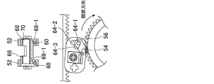
- the support body (52) includes a support section (in the embodiment, a V-shaped groove 64 and a support section) that displaceably supports the rotating body engagement section (62) of the engagement displacement member (56).
- the support portion (64) engages with the support engagement portion when the rotating body engagement portion (62) is in the limit direction limit position and the reverse rotation direction limit position.
- the support center portion (64-1) and the rotating body engaging portion are displaced from the reverse rotation direction limit position to the forward rotation direction limit position along the arcuate path, the support body engagement is displaced accordingly.
- the body engaging portion (62) is guided to be displaced from the support central portion (64-1), and the support engaging portion is engaged when the rotational engaging portion (62) comes in the middle of the arcuate path.
- a door closing guide surface (64-3) extending from the support central portion (64-1) adapted to prevent relative displacement of the portion (62) with respect to the support (52). can do.
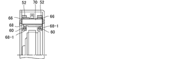
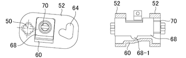
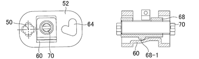
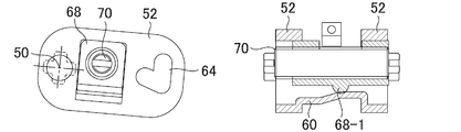
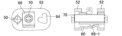
- this door closing prevention device Adjacent to the rotating body (38), it has a pressing member (68) provided parallel to the pivot (50) of the support (52),
- the support body (52) includes an insertion hole (66) through which the pressing member (68) passes, and includes a displacement preventing member (60) having the elasticity described above.
- the insertion hole (66) moves the pressing member (68) when the rotating body engaging portion (62) is moved toward the reverse rotation limit position and the support (52) is displaced around the pivot (50). Relative displacement with respect to The elastic displacement blocking member (60) can be pressed and engaged with the pressing member in accordance with the displacement of the support (52), thereby preventing the support from pivoting.
- the pressing member (68) is screw-engaged with a screw member (70) provided along a pivot parallel to the pivot (50) of the support (52), and the screw member (70) is moved around the pivot. , It can be displaced in the axial direction, whereby the degree of pressing engagement of the pressing member (68) with respect to the displacement preventing member (60) can be adjusted.
- the pressing member (68) has a pressing portion (68-1) that protrudes toward the elastic displacement preventing member (60) and has an inclined surface inclined in the direction of the pivot (50).
- the screw member (70) By rotating the screw member (70), the position of the inclined surface with respect to the elastic displacement preventing member (60) can be adjusted, and the degree of pressing engagement of the pressing member (68) with respect to the displacement preventing member (60) can be adjusted. It can be adjustable.
- the displacement preventing member (60) having elasticity is provided so as to incline in the direction of the pivot (50), and the pressing member (68) projects toward the displacement preventing member (60) having elasticity. It has a pressing part (68-1), and the position of the pressing part with respect to the displacement prevention member (60) can be adjusted by a screw member.
- the present invention also provides The first gear (32) meshed with the rack (18) set in the opening / closing direction of the sliding door is provided, and the first gear ( 32) and a closed door driving device for storing a spring biasing force that rolls the first gear (32) in the opposite direction as the first gear (32) rolls, and a first gear meshed with the first gear (32).
- a brake device for braking the rotation of the second gear (38) when the second gear (38) is rotated in accordance with the movement of the sliding door toward the door closing position.
- An automatic door closing device including a drive device and a casing (30) for housing the braking device, the sliding door closing device set in the casing (30), wherein the rotating body is connected to the second gear.
- the rotating body engaging portion is a pin that engages with the teeth of the second gear.
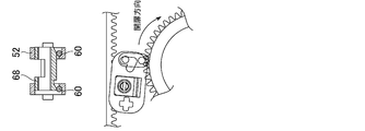
- FIG. 3 It is a figure which shows the state during door opening operation
- FIG. 3 shows the state during door opening operation
- the figure corresponding to FIG. 3 is shown on the upper side, and the figure corresponding to FIG. 2 is shown below.
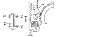
- FIG. 9 is a diagram showing a state when the force in the closing direction is applied to the sliding door again from the state of FIG. 8 where the sliding door is kept open in the door closing prevention device, and the sliding door is in the closing operation state;
- a diagram corresponding to FIG. 3 is shown above, and a diagram corresponding to FIG. 2 is shown below.
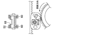
- the state when the sliding door is opened in another embodiment of the closing prevention device is shown, and the figure corresponding to FIG. 2 is shown on the left, and the figure corresponding to FIG. 3 is shown on the right.
- FIG. 10 shows a state where the hand is released from the opened sliding door and the sliding door moves in the closing direction from the state of FIG. 10 and is stopped by the door closing prevention device, corresponding to FIG. 2 on the left and corresponding to FIG.
- FIG. 10 the state in which the axial direction position of the pressing member is adjusted is shown, and the figure corresponding to FIG. 2 is shown on the left and the figure corresponding to FIG. 3 is shown on the right.
- FIG. 12 the state in which the opened sliding door is prevented from closing is fastened, and the figure corresponding to FIG. 2 is shown on the left and the figure corresponding to FIG. 3 is shown on the right.
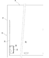
- FIG. 1 and 2 show a sliding door device 12 to which an automatic door closing device 10 equipped with a sliding door closing prevention device 1 according to the present invention is attached.
- the automatic door closing device 10 includes a rack 18 fixed to the upper frame portion 16 of the door frame 14 and a door driving device 22 fixed to the sliding door 20 and operatively connected to the rack 18.
- the door closing drive device 22 includes a casing 30 fixed to the sliding door 20, a gear (rotary member) 32 rotatably attached to the casing, and the rack 18 horizontally between the gear 32.
- An engagement holding member 36 that holds the engagement between the teeth of the rack 18 and the teeth of the gear 32, and the mainspring 31 provided concentrically with the gear inside the gear 32, and the sliding door 20 is closed.
- the spring 32 is meshed with the spring 32 for accumulating a spring biasing force that rolls the gear 32 in the opposite direction to the rolling.
- a braking device 40 for braking the rolling when the gear 32 is rolled in accordance with the movement of the sliding door 20 toward the closed position.
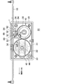
- reference numeral 42 denotes a spring member, which is attached to an inner wall surface of a side wall (not shown) of the casing provided in front of the same figure. This stops the rotation of the shaft by pressing two opposite surfaces of the hexagonal portion 44 integral with the shaft 33 to which one end of the mainspring is fixed.
- the hexagonal portion is rotated by a screwdriver or the like, the shaft is rotated, and the mainspring is wound or unwound.
- the door closing prevention device 1 includes a support body 52 that is pivotable around a pivot 50 with respect to a casing 30, and an engagement displacement member that is supported by the support body 52 so as to be displaceable and engaged with a gear 38. 56, the forward rotation direction limit position in the forward rotation direction with the forward rotation (clockwise in FIG. 2) and the reverse rotation (counterclockwise) of the gear 38 associated with the opening and closing operations of the sliding door 20, respectively.
- Engagement having a first pin (rotating body engaging portion) 54 that is displaceable along an arcuate path between the position in FIG. 6 (the position in FIG. 6) and the reverse rotation direction limit position in the reverse rotation direction (the position in FIG. 4).
- the first pin 54 of the engagement displacement member 56 is moved from the forward rotation direction limit position (FIG. 6) to the reverse rotation direction limit position (FIG. 4) by the gear 38.
- the displacement of the gear 54 is prevented with a predetermined elastic force, and the rotation of the gear 38 with which the first pin 54 is engaged is prevented, thereby preventing the gear 32 from rolling and preventing the sliding door from moving.
- a displacement preventing member 60 having elasticity for preventing the closing operation.
- the engagement displacement member 56 has a first pin 54 at one end, and a second pin (support engagement) that engages the engagement displacement member 56 with the support 52 so as to be displaceable at the other end. Part) 62.
- the support body 52 has a V-shaped groove (support portion) 64 that is slidably engaged with the engagement displacement member 56.
- the groove 64 has a heart shape as seen in FIGS. 4 to 6, and the first pin 54 rotates in the reverse rotation direction limit position when the gear 38 rotates in the forward direction (that is, rotates clockwise in accordance with the opening operation).
- the second pin 62 When moved from the position in FIG. 4 toward the forward rotation limit position (position in FIG. 6), the second pin 62 is displaced without resistance along the right portion of the groove 64 in the drawing. To do.
- the second pin 62 is on the left side as viewed in the drawing of the groove 64.
- the first pin 54 reaches the central portion of the arcuate path from the forward rotation limit position (position of FIG. 6) to the reverse rotation limit position (position of FIG. 4). It reaches the upper end of the left side portion of the plate so that the relative displacement with respect to the support 52 is prevented.
- the support 52 is counterclockwise about the pivot 50 by the first pin 54. Pivoted in the direction.
- the groove 64 is a support center portion that engages with the second pin 62 when the first pin 54 is in the forward rotation limit position (FIG. 6) and the reverse rotation limit position (position of FIG. 4).
- the door opening guide surface 64-2 extending from the support central portion 64-1 to guide the two pins 62, and the first pin 54 along the arcuate path from the forward rotation limit position (position in FIG. 6).
- the first pin 54 in the support center portion 64-1 is guided to be displaced from the support center portion 64-1,
- the support 5 of the second pin 62 It has a closing time of the guide surface 64-3 extending from the relative displacement by a length which is adapted to prevent the support central portion 64-1, the relative.
- the support 52 is composed of two members on the front side and the back side as viewed in FIG. 2, and is pivotally attached to the casing 30 of the door closing drive device.
- the support 52 extends parallel to the pivot 50 and has a rectangular cross section.
- a hole 66 is provided, and a pressing member 68 having a rectangular cross section that is pressed by the displacement preventing member 60 having elasticity is passed through the insertion hole 66.
- the pressing member 68 has a cylindrical shape, and is screw-engaged with a screw member 70 that is parallel to the pivot 50 of the support body 52 and rotatably provided on the casing 30, and rotates the screw member 70. Therefore, it can be displaced in the axial direction.
- Two displacement prevention members 60 having elasticity are provided at the bottom of the insertion hole 66 with an interval in the axial direction of the insertion hole, and the pressing member 68 is connected to the two displacement prevention members 60 having elasticity.
- a pressing portion 68-1 having an inclined surface is provided. Accordingly, by rotating the screw member 70 around its axis, the pressing member 68 screwed to the screw member 70 is displaced in the axial direction, and the corresponding pressing portion for the elastic displacement preventing member 60 is provided. The relative position of 68-1 can be adjusted.
- the elastic displacement preventing member 60 is further elastically deformed when a force of a certain level or more in the closing direction is applied to the sliding door stopped as described above, so that the support 52 is further counterclockwise.
- the first pin 54 is allowed to travel along the arcuate path and be displaced to the reverse rotation limit position (position in FIG. 4), whereby the sliding door is automatically operated by the closing drive device 22. It will be closed.
- the displacement preventing member 60 having elasticity is integrally formed so as to extend between two members constituting the support body 52, and the pressing member 68 is displaced relative to the support body 52. Accordingly, the protrusion (pressing portion) 68-1 provided on the pressing member is pressed and engaged with the displacement preventing member 60 having elasticity.
- Automatic door closing device 10 Sliding door device 12; Door frame 14; Upper frame portion 16; Rack 18; Sliding door 20; Door closing drive device 22; Casing 30; Gear 32; Gear 38; Braking device 40; Body 52; first pin (rotating body engaging portion) 54; engagement displacement member 56; elastic displacement preventing member 60; second pin (support body engaging portion) 62; groove (support portion) 64; Portion 64-1; door opening guide surface 64-2; door closing guide surface 64-3; insertion hole 66; pressing member 68; pressing portion 68-1; screw member 70
Landscapes
- Power-Operated Mechanisms For Wings (AREA)
- Closing And Opening Devices For Wings, And Checks For Wings (AREA)
Applications Claiming Priority (2)
| Application Number | Priority Date | Filing Date | Title |
|---|---|---|---|
| JP2008-087911 | 2008-03-28 | ||
| JP2008087911A JP4847490B2 (ja) | 2008-03-28 | 2008-03-28 | 引き戸の閉扉阻止装置及び閉扉阻止装置を備える自動閉扉装置 |
Publications (1)
| Publication Number | Publication Date |
|---|---|
| WO2009119797A1 true WO2009119797A1 (ja) | 2009-10-01 |
Family
ID=41113981
Family Applications (1)
| Application Number | Title | Priority Date | Filing Date |
|---|---|---|---|
| PCT/JP2009/056272 Ceased WO2009119797A1 (ja) | 2008-03-28 | 2009-03-27 | 引き戸の閉扉阻止装置及び閉扉阻止装置を備える自動閉扉装置 |
Country Status (3)
| Country | Link |
|---|---|
| JP (1) | JP4847490B2 (enExample) |
| TW (1) | TW201007002A (enExample) |
| WO (1) | WO2009119797A1 (enExample) |
Cited By (2)
| Publication number | Priority date | Publication date | Assignee | Title |
|---|---|---|---|---|
| EP2868852A1 (fr) * | 2013-11-05 | 2015-05-06 | Arcode SA | Dispositif universel pour la fermeture automatique d'un ouvrant coulissant, notamment porte de placard |
| EP2468997A3 (fr) * | 2010-12-23 | 2016-05-18 | Arcode SA | Dispositif universel pour la fermeture automatique d'un ouvrant coulissant, notamment porte de placard |
Families Citing this family (1)
| Publication number | Priority date | Publication date | Assignee | Title |
|---|---|---|---|---|
| JP6730210B2 (ja) * | 2016-11-01 | 2020-07-29 | 日東工器株式会社 | 引戸停止装置 |
Citations (3)
| Publication number | Priority date | Publication date | Assignee | Title |
|---|---|---|---|---|
| JPH10299331A (ja) * | 1997-02-25 | 1998-11-10 | Nippon Door Check Mfg Corp | 引き戸開閉装置 |
| JP2002339645A (ja) * | 2001-05-17 | 2002-11-27 | Miwa Lock Co Ltd | ハンガードアのフリーストッパー |
| JP2005054482A (ja) * | 2003-08-05 | 2005-03-03 | Atom Livin Tech Co Ltd | 自閉式引戸装置、自閉式引戸用ユニット及び自閉式引戸装置の組立方法 |
-
2008
- 2008-03-28 JP JP2008087911A patent/JP4847490B2/ja not_active Expired - Fee Related
-
2009
- 2009-03-27 WO PCT/JP2009/056272 patent/WO2009119797A1/ja not_active Ceased
- 2009-03-27 TW TW98110161A patent/TW201007002A/zh not_active IP Right Cessation
Patent Citations (3)
| Publication number | Priority date | Publication date | Assignee | Title |
|---|---|---|---|---|
| JPH10299331A (ja) * | 1997-02-25 | 1998-11-10 | Nippon Door Check Mfg Corp | 引き戸開閉装置 |
| JP2002339645A (ja) * | 2001-05-17 | 2002-11-27 | Miwa Lock Co Ltd | ハンガードアのフリーストッパー |
| JP2005054482A (ja) * | 2003-08-05 | 2005-03-03 | Atom Livin Tech Co Ltd | 自閉式引戸装置、自閉式引戸用ユニット及び自閉式引戸装置の組立方法 |
Cited By (2)
| Publication number | Priority date | Publication date | Assignee | Title |
|---|---|---|---|---|
| EP2468997A3 (fr) * | 2010-12-23 | 2016-05-18 | Arcode SA | Dispositif universel pour la fermeture automatique d'un ouvrant coulissant, notamment porte de placard |
| EP2868852A1 (fr) * | 2013-11-05 | 2015-05-06 | Arcode SA | Dispositif universel pour la fermeture automatique d'un ouvrant coulissant, notamment porte de placard |
Also Published As
| Publication number | Publication date |
|---|---|
| JP2009243056A (ja) | 2009-10-22 |
| TW201007002A (en) | 2010-02-16 |
| JP4847490B2 (ja) | 2011-12-28 |
| TWI351463B (enExample) | 2011-11-01 |
Similar Documents
| Publication | Publication Date | Title |
|---|---|---|
| KR100823138B1 (ko) | 도어 스토퍼 | |
| TWI547633B (zh) | 可動傢俱部分用的關閉及緩衝裝置 | |
| US20150211279A1 (en) | Rotation and stop retention switching apparatus | |
| WO2009119797A1 (ja) | 引き戸の閉扉阻止装置及び閉扉阻止装置を備える自動閉扉装置 | |
| JP5296893B2 (ja) | 自閉式引戸の閉じ停止装置 | |
| JP2009215799A (ja) | 引戸の引込み装置 | |
| JP6516198B2 (ja) | 扉用閉鎖制動装置 | |
| JP4829713B2 (ja) | 開口部閉鎖部材の制動装置及びそれを有する開口部閉鎖部材 | |
| EP2389490B1 (en) | Mechanism for smooth opening and retaining a car door in a desired position | |
| JP2012167522A (ja) | 扉用減速機構付き閉鎖装置 | |
| JP5131899B2 (ja) | 自閉式引戸の閉じ停止装置 | |
| JP4560002B2 (ja) | 引戸の制動装置 | |
| JP5014319B2 (ja) | ドアクローザー | |
| JP2010001680A (ja) | 回動扉の開閉装置 | |
| JP2002339648A (ja) | 引戸制動装置 | |
| JP2016070026A (ja) | 自閉式引き戸の閉動作抑制構造 | |
| JP4589841B2 (ja) | 流体摩擦抵抗型制動装置 | |
| JP5083604B2 (ja) | 引き戸クローザ | |
| JP4986474B2 (ja) | 扉の回動制動装置及び扉装置 | |
| JP3774369B2 (ja) | ドアクローザ | |
| JP2005054482A (ja) | 自閉式引戸装置、自閉式引戸用ユニット及び自閉式引戸装置の組立方法 | |
| JP2002188352A (ja) | ドア用遅延ストップ装置 | |
| JP2008253595A5 (enExample) | ||
| JP4549192B2 (ja) | 扉開閉遅延機構 | |
| JP2012087593A (ja) | 車両用ドアチェック装置 |
Legal Events
| Date | Code | Title | Description |
|---|---|---|---|
| 121 | Ep: the epo has been informed by wipo that ep was designated in this application |
Ref document number: 09724131 Country of ref document: EP Kind code of ref document: A1 |
|
| NENP | Non-entry into the national phase |
Ref country code: DE |
|
| 122 | Ep: pct application non-entry in european phase |
Ref document number: 09724131 Country of ref document: EP Kind code of ref document: A1 |