WO2009104592A1 - 建設機械 - Google Patents
建設機械 Download PDFInfo
- Publication number
- WO2009104592A1 WO2009104592A1 PCT/JP2009/052675 JP2009052675W WO2009104592A1 WO 2009104592 A1 WO2009104592 A1 WO 2009104592A1 JP 2009052675 W JP2009052675 W JP 2009052675W WO 2009104592 A1 WO2009104592 A1 WO 2009104592A1
- Authority
- WO
- WIPO (PCT)
- Prior art keywords
- cover
- engine
- heat exchanger
- exhaust port
- cooling air
- Prior art date
Links
Images


Classifications
-
- E—FIXED CONSTRUCTIONS
- E02—HYDRAULIC ENGINEERING; FOUNDATIONS; SOIL SHIFTING
- E02F—DREDGING; SOIL-SHIFTING
- E02F9/00—Component parts of dredgers or soil-shifting machines, not restricted to one of the kinds covered by groups E02F3/00 - E02F7/00
-
- B—PERFORMING OPERATIONS; TRANSPORTING
- B60—VEHICLES IN GENERAL
- B60K—ARRANGEMENT OR MOUNTING OF PROPULSION UNITS OR OF TRANSMISSIONS IN VEHICLES; ARRANGEMENT OR MOUNTING OF PLURAL DIVERSE PRIME-MOVERS IN VEHICLES; AUXILIARY DRIVES FOR VEHICLES; INSTRUMENTATION OR DASHBOARDS FOR VEHICLES; ARRANGEMENTS IN CONNECTION WITH COOLING, AIR INTAKE, GAS EXHAUST OR FUEL SUPPLY OF PROPULSION UNITS IN VEHICLES
- B60K11/00—Arrangement in connection with cooling of propulsion units
- B60K11/02—Arrangement in connection with cooling of propulsion units with liquid cooling
- B60K11/04—Arrangement or mounting of radiators, radiator shutters, or radiator blinds
-
- B—PERFORMING OPERATIONS; TRANSPORTING
- B60—VEHICLES IN GENERAL
- B60K—ARRANGEMENT OR MOUNTING OF PROPULSION UNITS OR OF TRANSMISSIONS IN VEHICLES; ARRANGEMENT OR MOUNTING OF PLURAL DIVERSE PRIME-MOVERS IN VEHICLES; AUXILIARY DRIVES FOR VEHICLES; INSTRUMENTATION OR DASHBOARDS FOR VEHICLES; ARRANGEMENTS IN CONNECTION WITH COOLING, AIR INTAKE, GAS EXHAUST OR FUEL SUPPLY OF PROPULSION UNITS IN VEHICLES
- B60K11/00—Arrangement in connection with cooling of propulsion units
- B60K11/08—Air inlets for cooling; Shutters or blinds therefor
-
- E—FIXED CONSTRUCTIONS
- E02—HYDRAULIC ENGINEERING; FOUNDATIONS; SOIL SHIFTING
- E02F—DREDGING; SOIL-SHIFTING
- E02F9/00—Component parts of dredgers or soil-shifting machines, not restricted to one of the kinds covered by groups E02F3/00 - E02F7/00
- E02F9/08—Superstructures; Supports for superstructures
- E02F9/0858—Arrangement of component parts installed on superstructures not otherwise provided for, e.g. electric components, fenders, air-conditioning units
- E02F9/0891—Lids or bonnets or doors or details thereof
-
- B—PERFORMING OPERATIONS; TRANSPORTING
- B60—VEHICLES IN GENERAL
- B60Y—INDEXING SCHEME RELATING TO ASPECTS CROSS-CUTTING VEHICLE TECHNOLOGY
- B60Y2200/00—Type of vehicle
- B60Y2200/40—Special vehicles
- B60Y2200/41—Construction vehicles, e.g. graders, excavators
-
- F—MECHANICAL ENGINEERING; LIGHTING; HEATING; WEAPONS; BLASTING
- F01—MACHINES OR ENGINES IN GENERAL; ENGINE PLANTS IN GENERAL; STEAM ENGINES
- F01P—COOLING OF MACHINES OR ENGINES IN GENERAL; COOLING OF INTERNAL-COMBUSTION ENGINES
- F01P11/00—Component parts, details, or accessories not provided for in, or of interest apart from, groups F01P1/00 - F01P9/00
- F01P11/10—Guiding or ducting cooling-air, to, or from, liquid-to-air heat exchangers
Definitions
- the present invention relates to a construction machine such as a hydraulic excavator, a hydraulic crane, or a wheel loader, and more particularly to a construction machine provided with an exterior cover that covers a mounted device such as an engine.
- a hydraulic excavator as a construction machine is provided with a self-propelled lower traveling body, an upper revolving body that is turnably mounted on the lower traveling body, and a front-rear side of the upper revolving body that can be raised and lowered. It is roughly constituted by a working device.
- the upper swing body is mounted on the rear side of the swing frame that forms the support structure, the engine that drives the hydraulic pump, the cooling fan that is driven to rotate by the engine, and the cooling fan.
- a heat exchanger such as a radiator and an oil cooler, and an exterior cover provided on the swivel frame to cover equipment mounted on the engine, a cooling fan, a heat exchanger, and the like.
- the exterior cover is composed of an upper surface plate provided horizontally extending above each mounted device, and left and right side plates extending downward from the left and right ends of the upper surface plate toward the swivel frame.
- the upper surface plate is provided with a large opening for inspecting and maintaining an engine, a heat exchanger, and the like.
- an engine cover that can be opened and closed is attached to the top plate so as to close the opening, and the engine cover is formed large in the left and right directions so as to cover from the heat exchanger to the hydraulic pump. Yes.
- an intake port is provided on the left side of the engine cover for sucking cooling air from the outside to the heat exchanger when the cooling fan is driven to rotate, and the heat exchanger and the cooling fan are passed on the right side. Exhaust ports for discharging cooling air to the outside are provided (see Patent Document 1: Japanese Patent Laid-Open No. 2000-303497, Patent Document 2: Japanese Utility Model Laid-Open No. 7-30321).
- the engine cover is attached to the top plate of the exterior cover so that it can be opened and closed, and the engine cover is provided with an intake port and an exhaust port for cooling air.
- a small opening is provided only on the upper side of the heat exchanger that requires periodic inspection work, cleaning work, etc., and a heat exchanger cover is provided on the top plate so as to cover only this heat exchanger. It is considered that the door can be opened and closed. In this case, it is possible to secure a space for the worker to get on the top plate and work.
- the present invention has been made in view of the above-described problems of the prior art, and an object of the present invention is to provide cooling air discharged from the exhaust port even when the intake port and the exhaust port are provided in a small heat exchanger cover. It is an object of the present invention to provide a construction machine that can be discharged to a place away from the vehicle and can improve the cooling efficiency by a heat exchanger by preventing re-suction of warm air.
- Another object of the present invention is to guide the cooling air flowing in the exterior cover by the cooling fan toward the exhaust port provided in the engine cover so that the cooling air can be efficiently distributed in the exterior cover. Is to provide a construction machine.
- a construction machine includes a vehicle body frame having a support structure and a work device attached to the front side, a counterweight provided on the rear side of the vehicle body frame, and a front side of the counterweight, Mounted on the engine, a hydraulic pump provided on one side of the engine in the left and right directions, and driven by the engine, and the hydraulic pump located on the opposite side in the left and right directions and attached to the engine
- a cooling fan that sucks cooling air from the outside, a heat exchanger that is located upstream of the cooling fan in the flow direction of the cooling air and is provided facing the cooling fan, the engine, the hydraulic pump, the heat It comprises an exterior cover provided on the vehicle body frame to cover the mounted equipment including the exchanger.
- the configuration of the present invention employs a configuration in which the exterior cover includes an engine cover provided above the engine, and the engine cover aligned in the left and right directions.
- a heat exchanger cover provided on the heat exchanger so as to be openable and closable and having a bulging upper surface that bulges upward compared to the upper surface of the engine cover, and facing the heat exchanger on the side surface of the vehicle body frame
- a side cover provided on the side of the heat exchanger, the heat exchanger cover being positioned on the side of the side cover and sucking outside air as cooling air; and the heat exchanger positioned on the side of the engine cover.
- One exhaust port for discharging the cooling air that has passed through the engine cover in a horizontal direction on the engine cover is provided, and the engine cover is separated from the one exhaust port provided in the heat exchanger cover In that a configuration in which the other exhaust port for discharging the cooling air in location.
- the cooling air warmed after passing through the heat exchanger can be discharged in the horizontal direction along the upper surface of the engine cover from one exhaust port provided in the heat exchanger cover. Thereby, the warm cooling air can be discharged in a direction away from the suction port of the heat exchanger cover.
- the intake port can supply the cooled cooling air to the heat exchanger, and the cooling efficiency of the fluid by the heat exchanger can be improved.
- the heat exchanger cover has a vertical surface extending substantially vertically downward from the bulging upper surface toward the upper surface of the engine cover, and the one exhaust port has the vertical surface.
- the configuration is that it is provided on the surface.
- one exhaust port can be provided as a lateral opening on the vertical surface of the heat exchanger cover, so that engine operating noise (noise) can be prevented from leaking directly from the exhaust port to the outside. Can improve the silence. Further, the sideways exhaust port can reduce the intrusion of rainwater, dust and the like into the exterior cover, and can also prevent clogging due to mud and the like.
- the one exhaust port provided in the heat exchanger cover and the other exhaust port provided in the engine cover are arranged side by side in the left and right directions. is there. Thereby, the cooling air discharged from the other exhaust port flows in a direction away from the intake port by the wind of the cooling air discharged in the horizontal direction from the one exhaust port, and can be reliably prevented from being sucked again. .
- a fire wall is provided in the exterior cover to block between the engine and the hydraulic pump, and cooling air that has passed around the engine is passed through the fire wall to the other cover.
- an air guide plate is provided to guide the exhaust port.
- the firewall is provided with a wind guide plate that guides the cooling air that has passed around the engine toward the other exhaust port provided in the engine cover, so that a firewall that obstructs the flow of the cooling air is provided. Even in this case, the cooling air to be discharged by the air guide plate can be smoothly circulated toward the other exhaust port, and each part can be efficiently cooled.
- the air guide plate is disposed at a position covering the muffler device for discharging the exhaust gas of the engine from above.
- the muffler device which becomes an obstacle in the exterior cover can be avoided, and the cooling air can be smoothly discharged from the other exhaust port.
- the air guide plate can block noise generated in the muffler device, and can reduce the volume during operation.
- the counterweight includes a center weight portion having a high height, and left and right side weight portions that are curved toward the front side while extending left and right from the center weight portion. And the rear side of the heat exchanger cover is arranged on the upper surface side of the central weight portion.
- the rear side of the heat exchanger cover can be arranged using the upper surface side of the central weight portion of the counterweight.
- a self-propelled lower traveling body an upper revolving body that is turnably mounted on the lower traveling body, and a left and right central portion on the front side of the upper revolving body.
- the vehicle body frame is a revolving frame in which the vehicle body frame constitutes the upper revolving body and the work device is attached to the front side, and the revolving frame is on the side of the work device.
- a cab having a driver's seat on which the operator is seated is provided, the engine is positioned on the front side of the counterweight, and is placed horizontally on the swivel frame so as to extend in the left and right directions, and the heat exchanger Is configured to be disposed between the engine and the side cover on the rear side of the cab.
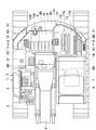
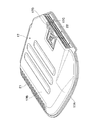
- FIG. 1 is a front view showing a hydraulic excavator according to an embodiment of the present invention. It is a top view which expands and shows the hydraulic shovel of FIG. It is the external appearance perspective view which looked at the upper turning body from the right rear side. It is the external appearance perspective view which looked at the upper turning body of the state which opened the heat exchanger cover from the same position as FIG.
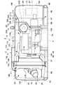
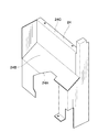
- FIG. 5 is an enlarged cross-sectional view of the upper swing body viewed from an arrow VV direction in FIG. 2. It is an external appearance perspective view which expands and shows a heat exchanger cover. It is an external appearance perspective view which expands and shows a firewall and a baffle plate in the assembled state. It is an external appearance perspective view which shows the firewall in FIG. 7 alone. It is an external appearance perspective view which shows the baffle plate in FIG. 7 alone.
- reference numeral 1 denotes a crawler hydraulic excavator as a construction machine.
- the hydraulic excavator 1 is mounted on a self-propelled lower traveling body 2 and on the lower traveling body 2 so as to be turnable.
- 2 is constituted roughly by an upper swing body 3 constituting a vehicle body and a work device 4 provided on the front side of the upper swing body 3 so as to be able to move up and down and performing excavation work of earth and sand.
- the revolving frame 5 is a turning frame as a body frame constituting a part of the upper turning body 3, and the turning frame 5 is formed as a support structure. Then, as shown in FIG. 5, the revolving frame 5 is provided with a bottom plate 5A made of a thick steel plate or the like extending in the front and rear directions, and a standing space on the bottom plate 5A.
- Left and right vertical plates 5B extending in the front and rear directions, and left and right left and right side frames 5D and 5D arranged at intervals on the left and right sides of the vertical plates 5B and extending in the front and rear directions,
- the base end side is fixed to the bottom plate 5A and the vertical plate 5B and extends in the left and right directions, and a plurality of extension beams 5E for supporting the left and right side frames 5C and 5D at the distal end side, the bottom plate 5A and the side frame
- a plurality of undercovers 5F provided between 5C and 5D are roughly configured.
- the working device 4 is attached to the revolving frame 5 in front of each vertical plate 5 ⁇ / b> B so as to move up and down.
- a cab mounted on the left front side of the revolving frame 5 on the side of the work device 4, and the cab 6 is used by an operator.
- a driver's seat 7 on which an operator is seated, a travel operation lever, a work operation lever, and the like (all not shown).
- the counterweight 8 is a counterweight attached to the rear end of the revolving frame 5, and this counterweight 8 is formed as an arcuate heavy object in order to balance the weight with the work device 4. More specifically, as shown in FIGS. 3 and 4, the counterweight 8 includes a central weight portion 8 ⁇ / b> A that is located in the center portion in the left and right directions and protrudes upward and has a high height dimension, and the central weight portion 8 ⁇ / b> A.
- the left and right side weight portions 8B and 8C are curved toward the front side while extending in the left and right directions.
- the left and right side weight portions 8B and 8C are provided with a low height near the lower side of the center weight portion 8A, so that the central portion of the overall shape of the counterweight 8 protrudes upward. It is formed in a mountain shape. Further, the central weight portion 8A has an upper surface 8D that is substantially the same height as an engine cover 15 described later, and a rear end side of the heat exchanger cover 17 is disposed on the upper side.
- Reference numeral 9 denotes an engine which is one of the mounted devices provided on the rear side of the turning frame 5, and the engine 9 is mounted on the front side of the counterweight 8 in a horizontally placed state extending in the left and right directions. ing. Further, as shown in FIG. 5, the engine 9 is provided with an output shaft 9A whose axis is in the left and right directions. A cooling fan 12, a generator (not shown), etc., which will be described later, are connected to the output shaft 9A via a belt 9B so as to be rotationally driven. On the other hand, a hydraulic pump 11 that discharges hydraulic oil as pressure oil by being driven by an output shaft 9A is attached to one side of the engine 9 in the left and right directions (right side in the embodiment).
- the engine 9 is provided with a muffler device 10 for discharging exhaust gas to the outside.
- the muffler device 10 includes an exhaust pipe 10A connected to the exhaust side of the engine 9, and a substantially cylindrical muffler provided in the middle of the exhaust pipe 10A so as to extend forward and rearward on the upper right side of the engine 9.
- the device 10B and a bracket 10C for attaching the silencer 10B to the engine 9 are roughly configured.
- Numeral 12 is a suction type cooling fan attached to the engine 9 and located on the opposite side of the hydraulic pump 11 to the left and right (left side in the embodiment) across the engine 9.
- the cooling fan 12 is driven to rotate by the engine 9, thereby allowing external air to pass through the air inlet 21 of the heat exchanger cover 17 of the exterior cover 14 and the left side air inlet 20 of the left side door cover 18 which will be described later.
- the cooling air is sucked in, and the sucked cooling air is supplied to the heat exchanger 13 described later.
- a part of the cooling air that has warmed up after passing through the heat exchanger 13 is discharged to the outside through the exhaust port 22 of the heat exchanger cover 17, and the other cooling air flows around the engine 9 toward the right side.
- the air is discharged to the outside from the right exhaust port 23 of the engine cover 15 and the bottom side of the revolving frame 5.
- the heat exchanger 13 is a heat exchanger provided on the swivel frame 5 at the rear side of the cab 6.
- the heat exchanger 13 constitutes one of the mounted devices mounted on the revolving frame 5 and includes, for example, a radiator that cools engine cooling water, an oil cooler that cools hydraulic oil, and the like. Further, the heat exchanger 13 is located upstream of the cooling fan 12 between the cab 6 and the counterweight 8 with respect to the flow direction of the cooling air, that is, between the left side door cover 18 and the cooling fan 12 described later.
- the cooling fan 12 is provided so as to face the cooling fan 12.
- the periphery of the heat exchanger 13 is surrounded by a rectifying support frame 13A, and a heat exchanger is sealed by sealing an upper portion of the support frame 13A with a heat exchanger cover 17 described later.
- a seal member 13B for preventing the warm air that has passed through the vessel 13 from flowing back is provided to extend in the forward and backward directions.
- Reference numeral 14 denotes an exterior cover provided on the revolving frame 5, and this exterior cover 14 covers the engine 9, the heat exchanger 13, and the like provided as the mounted equipment, and will be described later with an engine cover 15 and a heat exchanger cover 17.
- the left side door cover 18 and the right side door cover 19 are roughly configured.
- the hydraulic excavator 1 is configured as an ultra-small turning machine in which the upper turning body 3 can turn substantially within the vehicle width of the lower traveling body 2.
- the upper swing body 3 is formed compactly so that the counterweight 8 is disposed in front of the rear end of the lower traveling body 2 and the rear side of the counterweight 8 is substantially circular.
- the space for installing the heat exchanger 13 is reduced as the upper swing body 3 is formed in a small size. For this reason, in order to obtain a required cooling performance, it is necessary to form the heat exchanger 13 large on the upper side (higher on the upper side). Therefore, the upper position of the heat exchanger 13 protrudes above the installation position of the engine cover 15 constituting the exterior cover 14. As a result, the heat exchanger cover 17 covering the heat exchanger 13 is also swelled upward as compared with the engine cover 15.
- 15 is an engine cover that constitutes a part of the exterior cover 14, and the engine cover 15 is located on the rear side of the working device 4 and on the front side of the central weight portion 8 ⁇ / b> A of the counterweight 8 and covers the upper side of the engine 9.
- the engine cover 15 is fixedly attached in a state that cannot be opened and closed by means such as bolting or welding. More specifically, as shown in FIGS. 2 and 5, the engine cover 15 is positioned on the right side of the heat exchanger cover 17 so as to cover the upper side of the engine 9, the muffler device 10, and the hydraulic pump 11, and the counterweight. 8. It consists of the plate body extended substantially horizontally between the below-mentioned right side door cover 19 and the fuel tank 27. The engine cover 15 is disposed at substantially the same height as the central weight portion 8A of the counterweight 8.
- the engine cover 15 is formed as a large plate that covers the upper side of the engine 9, it is possible to secure a space for the operator to ride when performing inspection work, maintenance work, etc. of the heat exchanger 13 and the like. Can easily work on the engine cover 15. Further, the engine cover 15 is provided with a right exhaust port 23 to be described later for discharging the cooling air at a position away from the exhaust port 22 provided in the heat exchanger cover 17.
- the opening 16 is an opening formed at a position sandwiched between the counterweight 8 and the cab 6 between the engine cover 15 and a left side door cover 18 described later. As shown in FIGS. 4 and 5, the opening 16 is opened above the heat exchanger 13 and the belt 9 ⁇ / b> B of the engine 9 that require daily inspection work and periodic cleaning work. To do.
- Numeral 17 is a heat exchanger cover provided so as to be openable and closable above the heat exchanger 13 in order to close the opening 16.
- the heat exchanger cover 17 is arranged side by side with the engine cover 15 and the left side door cover 18 in the left and right directions, and constitutes a substantially trapezoidal lid that opens and closes the opening 16.
- the heat exchanger cover 17 is attached to the structure constituting the exterior cover 14 or the structure constituting the swivel frame 5 at the left end via a hinge or the like so as to be opened and closed.
- the heat exchanger cover 17 has a peripheral edge portion 17A that is in contact with the upper surface of the engine cover 15, the upper surface 8D of the central weight portion 8A of the counterweight 8, etc.
- a bulging upper surface 17B is formed by bulging upward from 17A. Thereby, the heat exchanger cover 17 can cover the large heat exchanger 13 on the upper side by the bulging upper surface 17B.
- the right end of the heat exchanger cover 17 is a vertical surface 17C extending substantially vertically downward from the bulging upper surface 17B toward the upper surface of the engine cover 15.
- the vertical surface 17C is for opening one exhaust port 22 to be described later in the horizontal direction.
- the vertical surface 17C has a rectangular shape elongated in the front and rear directions at a position slightly retracted from the right end of the bulging upper surface 17B. It is formed as a surface part.
- the heat exchanger cover 17 is provided with an opening / closing handle 17D located above the vertical surface 17C.
- an air inlet 21 to be described later is provided on the left side of the heat exchanger cover 17 so as to be located on the left side of the heat exchanger 13, and an exhaust port is provided on the right side of the heat exchanger cover 17 at the position of the vertical surface 17C. 22 is provided.
- the exhaust port 22 opens at a position spaced to the right of the cooling fan 12.
- Reference numeral 18 denotes a left side door cover as a left side cover constituting the left side of the exterior cover 14, and the left side door cover 18 has a structure in which, for example, the front part constitutes the structure or the revolving frame 5 constituting the exterior cover 14. It is attached to the body so that it can be opened and closed. When the left side door cover 18 is opened, inspection work, maintenance work, cleaning work, etc. of the heat exchanger 13, an air cleaner 26 described later, and the like can be performed.
- the left side door cover 18 is located facing the heat exchanger 13 and has a side surface portion 18A standing on the left side frame 5C, which is a side surface of the swivel frame 5, and an upper portion of the side surface portion 18A on the right side. And a curved surface portion 18B formed by bending in the direction. Further, a left side air inlet 20 described later is provided on the side surface portion 18A and the curved surface portion 18B of the left side door cover 18.
- the right side door cover 19 is a right side door cover as a right side cover constituting the right side of the exterior cover 14, and the right side door cover 19 includes a side surface portion 19A erected on the right side frame 5D of the revolving frame 5, It is constituted by a curved surface portion 19B formed by bending the upper portion of the side surface portion 19A leftward. And when the right side door cover 19 is opened, inspection work of the hydraulic pump 11, hydraulic equipment (not shown), etc. can be performed.
- Reference numeral 20 denotes a plurality of left side air inlets provided on the side surface 18A and the curved surface part 18B of the left side door cover 18, and the left side air inlets 20 have a plurality of slit-like openings and mesh-like openings. It is formed as. Each left side air inlet 20 sucks outside air as cooling air when the cooling fan 12 is driven to rotate.
- the air inlet 21 is an air inlet provided in the heat exchanger cover 17, and the air inlet 21 is on the left side door cover 18 side of the bulging upper surface 17B, that is, on the upstream side of the heat exchanger 13 in the flow direction of cooling air. Is located. Further, the air inlet 21 of the heat exchanger cover 17 is formed as a slit-like opening arranged in a large number in the front and rear directions, almost like a part of the left side air inlet 20. And the air inlet 21 sucks external air as cooling air when the cooling fan 12 is rotationally driven, like the left side air inlets 20.
- Reference numeral 22 denotes one exhaust port provided in the heat exchanger cover 17.
- the exhaust port 22 is provided on the right side of the engine cover 15 opposite to the intake port 21, that is, on the vertical surface 17 ⁇ / b> C of the heat exchanger cover 17. It has been.
- the exhaust port 22 is formed as a large number of grid-like openings arranged on the vertical surface 17C.
- the exhaust port 22 is provided on the vertical surface 17C to discharge the cooling air that has passed through the heat exchanger 13 in the horizontal direction on the engine cover 15.
- the exhaust port 22 provided in the small heat exchanger cover 17 is close to the intake port 21.
- the exhaust port 22 opens to the right side of the cooling fan 12 and can discharge the cooling air in the horizontal direction along the upper surface of the engine cover 15.
- the cooling air warmed after passing through the heat exchanger 13 can be discharged in a direction away from the intake port 21 and the like, and the warm air discharged from the exhaust port 22 is prevented from being sucked into the intake port 21 again. can do.
- the operating sound (noise) of the engine 9 does not leak directly from the exhaust port 22 that opens sideways, but on the bulging upper surface 17B of the heat exchanger cover 17. A part of the operating sound that collided leaks from the exhaust port 22. Further, the sideways exhaust port 22 can reduce the intrusion of rainwater, dust and the like into the exterior cover 14, and mud etc. are difficult to accumulate and can prevent clogging.
- the cooling air discharged from the right exhaust port 23 by the wind force can be pressed to the right side. Thereby, the cooling air discharged from the right exhaust port 23 can be prevented from being sucked into the intake ports 20 and 21 again.
- the right exhaust port 23 is a right exhaust port as the other exhaust port provided on the right side of the engine cover 15.
- the right exhaust port 23 is disposed at a position on the right side from the exhaust port 22 provided in the heat exchanger cover 17 and arranged side by side in the left and right directions, and discharges cooling air that has passed around the engine 9. It is. For this reason, the right exhaust port 23 is disposed above the hydraulic pump 11 on the right side of the engine 9.
- the right exhaust port 23 is greatly separated in the left and right directions with respect to the respective intake ports 20 and 21, and the cooling air is inclined diagonally upward to the right by a second inclined plate 25 ⁇ / b> C of the air guide plate 25 described later. Therefore, it is possible to prevent the circulation of the exhausted cooling air from the intake ports 20 and 21.
- firewall 24 that shields between the engine 9 and the hydraulic pump 11 to prevent the hydraulic oil from scattering to the engine 9 side.
- the firewall 24 is a firewall provided in the exterior cover 14, and the firewall 24 blocks between the engine 9 and the hydraulic pump 11.
- the firewall 24 is formed as a structure having strength against vibration, bending, and the like by, for example, bending a plurality of steel plates and fixing them together.
- a notch opening 24A is formed below the firewall 24 so as to straddle the mounting base of the hydraulic pump 11 with respect to the engine 9, and the upper side of the notch opening 24A is a muffler device. It is a recessed step portion 24B that is retracted to accommodate ten silencers 10B.
- a mounting portion 24C for mounting a wind guide plate 25 described later is formed at the upper end portion of the recessed step portion 24B.
- the lower portion of the firewall 24 is attached to the vertical plate 5B of the revolving frame 5, and the upper portion is attached to the engine cover 15 or the like via the air guide plate 25.
- the firewall 24 can prevent the leaked hydraulic oil from scattering to the engine 9 side even when the hydraulic oil leaks around the hydraulic pump 11, and can prevent a fire or the like. .
- the air guide plate 25 is a wind guide plate provided on the upper part of the firewall 24 so as to cover the silencer 10B of the muffler device 10.
- the air guide plate 25 guides the cooling air that has passed around the engine 9 toward the right exhaust port 23 of the engine cover 15, avoiding the silencer 10 ⁇ / b> B of the muffler device 10.
- the air guide plate 25 is formed, for example, by bending a steel plate. As shown in FIGS. 7 and 9, the air guide plate 25 has a bowl-shaped main body portion 25A and a left side from the main body portion 25A to guide the cooling air upward.
- a first inclined plate 25B extending downward and a second inclined plate 25C extending upward from the main body 25A toward the right side in order to guide the cooling air to the right exhaust port 23 of the engine cover 15. Has been.
- the air guide plate 25 can guide the cooling air to the right exhaust port 23 of the engine cover 15 and discharge it to the outside so as to avoid the firewall 24 that obstructs the flow of the cooling air. Can be efficiently cooled. Further, since the portion of the air guide plate 25 connected to the right exhaust port 23 is the second inclined plate 25C, the cooling air can be discharged obliquely upward to the right by the second inclined plate 25C. Wind can be separated from each inlet 20,21.
- the air guide plate 25 is disposed at a position that covers the silencer 10B of the muffler device 10 from the upper side, the silencer 10B that becomes an obstacle in the exterior cover 14 is avoided, and cooling air is supplied to the engine cover 15. It is possible to discharge smoothly from the right exhaust port 23. Further, the air guide plate 25 can block the noise generated in the muffler device 10 and can reduce the volume during operation.
- Reference numeral 26 denotes an air cleaner disposed between the heat exchanger 13 and the left side door cover 18.
- the air cleaner 26 is connected to the intake side of the engine 9 and supplies clean air to the engine 9. It is.
- a fuel tank 27 is located on the front side of the hydraulic pump 11 and is provided on the revolving frame 5. The fuel tank 27 stores fuel to be supplied to the engine 9.
- the hydraulic excavator 1 according to the present embodiment has the above-described configuration. Next, the operation of the hydraulic excavator 1 will be described.
- the operator gets on the cab 6 and sits in the driver's seat 7.
- the lower traveling body 2 can be driven to move the hydraulic excavator 1 forward or backward.
- the operator seated on the driver's seat 7 can perform work such as excavation of earth and sand by operating the operation lever for working to raise and lower the working device 4.
- the cooling fan 12 when the cooling fan 12 is driven to rotate, the external air is cooled via the left side intake ports 20 provided in the left side door cover 18 of the exterior cover 14 and the intake ports 21 provided in the heat exchanger cover 17. Inhaled as wind, this cooling wind can be supplied to the heat exchanger 13 to cool fluid such as engine coolant and hydraulic oil.
- the other cooling air flows around the engine 9 toward the right side, and a part thereof is discharged to the outside from the right exhaust port 23 provided in the engine cover 15.
- the air guide plate 25 provided on the firewall 24 sends the cooling air to the right side exhaust of the engine cover 15 so as to avoid the firewall 24 and the silencer 10B of the muffler device 10 that obstruct the flow of the cooling air. It can be led to the mouth 23 and discharged outside.
- the air guide plate 25 since the air guide plate 25 has a portion that is connected to the right exhaust port 23 as the second inclined plate 25C, the cooling air is discharged obliquely upward and rightward from the right exhaust port 23 along the angle of the second inclined plate 25C. can do.
- the right exhaust port 23 is arranged at a position aligned with the exhaust port 22 of the heat exchanger cover 17 in the left and right directions. As a result, the cooling air discharged from the exhaust port 23 is pressed to the right by the wind of the cooling air discharged from the one exhaust port 22 in the horizontal direction, and flows in a direction away from the intake ports 20, 21. Suction can be reliably prevented.
- the remaining cooling air that has circulated around the engine 9 toward the right side is discharged to the outside through an opening provided in the under cover 5F of the revolving frame 5.
- the heat exchanger cover 17 of the exterior cover 14 is provided with the intake port 21 that is located on the left side and sucks outside air as cooling air, and on the right side opposite to the intake port 21.
- An exhaust port 22 for discharging the cooling air that has passed through the heat exchanger 13 is provided, and the exhaust port 22 is configured to discharge the cooling air in the horizontal direction along the upper surface of the engine cover 15. Therefore, since the warm cooling air that has passed through the heat exchanger 13 can be discharged horizontally along the upper surface of the engine cover 15 from the exhaust port 22 provided in the heat exchanger cover 17, the warm cooling air is The heat exchanger cover 17 can be discharged in a direction away from the inlet 21 of the heat exchanger cover 17.
- the intake port 21 and the exhaust port 22 are provided in the small heat exchanger cover 17 and the intake port 21 and the exhaust port 22 are close to each other, the warm cooling air exhausted from the exhaust port 22 can be 21 can be prevented from being sucked again.
- the inlet 21 can supply the cooled cooling air to the heat exchanger 13, and the cooling efficiency of the fluid such as engine cooling water and hydraulic oil by the heat exchanger 13 can be improved.
- the exhaust port 22 is provided on the vertical surface 17C of the heat exchanger cover 17, the exhaust port 22 can be opened sideways, and the operating sound of the engine 9 is directed upward from the exhaust port 22. Direct leakage can be prevented, and the quietness during work can be improved. Further, the sideways exhaust port 22 can reduce the intrusion of rainwater, dust and the like into the outer cover 14, and can also prevent clogging due to mud and the like.
- the exhaust port 22 provided in the heat exchanger cover 17 and the exhaust port 23 provided in the engine cover 15 are arranged side by side in the left and right directions, one of the exhaust ports 22 supplies cooling air.
- the cooling air discharged from the other exhaust port 23 can be pressed to the right side.
- the cooling air discharged from the right exhaust port 23 provided in the engine cover 15 flows in a direction away from the intake ports 20 and 21, and the re-suction of the cooling air can be prevented more reliably.
- the firewall 24 that shields between the engine 9 and the hydraulic pump 11 in the exterior cover 14 is provided, even if the hydraulic oil leaks around the hydraulic pump 11, the leaked hydraulic oil remains on the engine 9 side. Can be prevented, fire can be prevented, and reliability can be improved.
- the firewall 24 is provided with an air guide plate 25 that guides the cooling air that has passed around the engine 9 toward the right exhaust port 23 provided in the engine cover 15.
- the air guide plate 25 guides the cooling air that has passed around the engine 9 toward the right exhaust port 23 provided in the engine cover 15.
- the air guide plate 25 is disposed at a position that covers the silencer 10B of the muffler device 10 from the upper side, the silencer 10B that becomes an obstacle in the exterior cover 14 is avoided, and the cooling air is supplied to the right exhaust port 23. Can be discharged smoothly. Further, the air guide plate 25 can block the noise generated in the muffler device 10 and can reduce the volume during operation.
- the counterweight 8 includes a central weight portion 8A having a high height dimension, and left and right side weight portions having a low height dimension which are curved leftward and rightward while extending from the central weight portion 8A to the left and right. Since it is constituted by 8B and 8C, the counterweight 8 can be increased in weight in a limited space. Further, the rear side of the heat exchanger cover 17 can be arranged using the upper surface side of the central weight portion 8A of the counterweight 8.
- a cooling fan may be provided separately from the engine, and may be rotationally driven using an electric motor, a hydraulic motor, or the like to supply cooling air to the heat exchange device.
- the engine cover 15 is described as being fixedly attached in a state where it cannot be opened and closed, it may be configured so that it can be opened and closed by removing bolts or the like or can be removed.
- left side door cover 18 and the right side door cover 19 constituting the exterior cover 14 are not limited to covers that can be opened and closed, and may be fixed side covers that do not open and close. Further, the left and right side door covers 18 and 19 may have an openable / closable cover on one side and a fixed cover on the other side.
- the explanation has been given by taking the hydraulic excavator 1 provided with the crawler type lower traveling body 2 as an example of the construction machine.
- the present invention is not limited to this, and may be applied to, for example, a hydraulic excavator provided with a wheel-type lower traveling body. Besides, it can be widely applied to other construction machines such as wheel loaders, dump trucks, lift trucks and the like.
Landscapes
- Engineering & Computer Science (AREA)
- Mining & Mineral Resources (AREA)
- Civil Engineering (AREA)
- General Engineering & Computer Science (AREA)
- Structural Engineering (AREA)
- Chemical & Material Sciences (AREA)
- Combustion & Propulsion (AREA)
- Transportation (AREA)
- Mechanical Engineering (AREA)
- Component Parts Of Construction Machinery (AREA)
- Cooling, Air Intake And Gas Exhaust, And Fuel Tank Arrangements In Propulsion Units (AREA)
Priority Applications (2)
| Application Number | Priority Date | Filing Date | Title |
|---|---|---|---|
| US12/679,369 US8550198B2 (en) | 2008-02-22 | 2009-02-17 | Construction machine |
| EP09712823.5A EP2248695B1 (de) | 2008-02-22 | 2009-02-17 | Baumaschine |
Applications Claiming Priority (2)
| Application Number | Priority Date | Filing Date | Title |
|---|---|---|---|
| JP2008041633A JP5172381B2 (ja) | 2008-02-22 | 2008-02-22 | 建設機械 |
| JP2008-041633 | 2008-02-22 |
Publications (1)
| Publication Number | Publication Date |
|---|---|
| WO2009104592A1 true WO2009104592A1 (ja) | 2009-08-27 |
Family
ID=40985472
Family Applications (1)
| Application Number | Title | Priority Date | Filing Date |
|---|---|---|---|
| PCT/JP2009/052675 WO2009104592A1 (ja) | 2008-02-22 | 2009-02-17 | 建設機械 |
Country Status (4)
| Country | Link |
|---|---|
| US (1) | US8550198B2 (de) |
| EP (1) | EP2248695B1 (de) |
| JP (1) | JP5172381B2 (de) |
| WO (1) | WO2009104592A1 (de) |
Cited By (2)
| Publication number | Priority date | Publication date | Assignee | Title |
|---|---|---|---|---|
| EP2365139A1 (de) * | 2010-03-08 | 2011-09-14 | Kobelco Construction Machinery Co., Ltd. | Konstruktionsmaschine mit Motorraum |
| EP3219856A1 (de) * | 2016-03-15 | 2017-09-20 | Hitachi Construction Machinery Co., Ltd. | Baumaschine |
Families Citing this family (25)
| Publication number | Priority date | Publication date | Assignee | Title |
|---|---|---|---|---|
| JP5706110B2 (ja) * | 2010-07-29 | 2015-04-22 | プレス工業株式会社 | 建設機械のキャブフレーム構造 |
| JP5033226B2 (ja) * | 2010-08-02 | 2012-09-26 | 株式会社小松製作所 | 作業車両 |
| JP2012106836A (ja) * | 2010-11-17 | 2012-06-07 | Tcm Corp | 産業車両用ディーゼル・パティキュレート・フィルター取付構造 |
| JP2012171596A (ja) * | 2011-02-24 | 2012-09-10 | Hitachi Constr Mach Co Ltd | 建設機械 |
| JP5509119B2 (ja) * | 2011-02-25 | 2014-06-04 | 株式会社小松製作所 | 建設車両 |
| JP5508351B2 (ja) * | 2011-06-30 | 2014-05-28 | 日立建機株式会社 | 作業機械 |
| JP5706793B2 (ja) * | 2011-09-20 | 2015-04-22 | 日立建機株式会社 | 発電電動機とこれを用いた電動車両 |
| JP5831111B2 (ja) * | 2011-10-03 | 2015-12-09 | コベルコ建機株式会社 | 建設機械の排気構造 |
| JP5758338B2 (ja) * | 2012-03-29 | 2015-08-05 | 株式会社クボタ | 作業機 |
| JP6122255B2 (ja) * | 2012-06-01 | 2017-04-26 | キャタピラー エス エー アール エル | 建設機械 |
| CN104114776B (zh) * | 2013-02-18 | 2016-01-20 | 株式会社小松制作所 | 液压挖掘机 |
| JP5821872B2 (ja) * | 2013-02-22 | 2015-11-24 | コベルコ建機株式会社 | 建設機械の吸気構造 |
| JP5733335B2 (ja) * | 2013-04-19 | 2015-06-10 | コベルコ建機株式会社 | 建設機械の排気構造 |
| JP5993830B2 (ja) * | 2013-10-30 | 2016-09-14 | 日立建機株式会社 | 建設機械 |
| JP5949730B2 (ja) * | 2013-11-07 | 2016-07-13 | コベルコ建機株式会社 | 建設機械の電装品配設構造 |
| JP6438341B2 (ja) * | 2014-10-15 | 2018-12-12 | ヤンマー株式会社 | 作業車両 |
| JP6458509B2 (ja) * | 2015-01-26 | 2019-01-30 | コベルコ建機株式会社 | 建設機械 |
| JP6391522B2 (ja) * | 2015-03-30 | 2018-09-19 | 株式会社クボタ | 作業機 |
| JP6510892B2 (ja) * | 2015-06-02 | 2019-05-08 | 日立建機株式会社 | 建設機械 |
| JP2017002509A (ja) * | 2015-06-08 | 2017-01-05 | 株式会社神戸製鋼所 | 建設機械の冷却構造 |
| JP6229694B2 (ja) * | 2015-06-08 | 2017-11-15 | コベルコ建機株式会社 | エンジンを備えた建設機械 |
| JP6495193B2 (ja) * | 2016-01-20 | 2019-04-03 | 株式会社日立建機ティエラ | 小型の建設機械 |
| WO2018025340A1 (ja) * | 2016-08-03 | 2018-02-08 | 株式会社小松製作所 | 作業車両 |
| JP2018159170A (ja) * | 2017-03-22 | 2018-10-11 | 三菱ロジスネクスト株式会社 | 荷役車両 |
| JP7273619B2 (ja) * | 2018-06-01 | 2023-05-15 | マニタウォック クレイン カンパニーズ, エルエルシー | クレーン下部走行体上のエンジン排気後処理システムのための取り付け配設 |
Citations (6)
| Publication number | Priority date | Publication date | Assignee | Title |
|---|---|---|---|---|
| JPH1159202A (ja) * | 1997-08-28 | 1999-03-02 | Kobe Steel Ltd | 建設機械の防音構造 |
| JPH11139171A (ja) * | 1997-11-10 | 1999-05-25 | Toyota Autom Loom Works Ltd | フォークリフトトラックのラジエータ冷却装置 |
| JP2002192960A (ja) * | 2000-10-18 | 2002-07-10 | Komatsu Ltd | 建設機械のエンジンフード |
| JP2003147806A (ja) * | 2001-11-09 | 2003-05-21 | Hitachi Constr Mach Co Ltd | 建設機械 |
| JP2004352066A (ja) * | 2003-05-28 | 2004-12-16 | Shin Caterpillar Mitsubishi Ltd | 建設機械のエンジンルーム構造及び建設機械のエンジン冷却装置 |
| JP2005145114A (ja) * | 2003-11-11 | 2005-06-09 | Shin Caterpillar Mitsubishi Ltd | 建設機械のエンジンフード、建設機械のエンジンルーム構造及び建設機械の冷却装置 |
Family Cites Families (16)
| Publication number | Priority date | Publication date | Assignee | Title |
|---|---|---|---|---|
| JPH08268088A (ja) * | 1995-03-31 | 1996-10-15 | Hitachi Constr Mach Co Ltd | 建設機械の冷却構造 |
| JPH08270444A (ja) * | 1995-03-31 | 1996-10-15 | Hitachi Constr Mach Co Ltd | 建設機械の冷却構造 |
| JP2000303497A (ja) | 1999-04-23 | 2000-10-31 | Hitachi Constr Mach Co Ltd | 建設機械の冷却装置及び建設機械のカバー |
| JP2001123836A (ja) * | 1999-10-26 | 2001-05-08 | Hitachi Constr Mach Co Ltd | 建設機械のエンジン冷却装置 |
| JP4450298B2 (ja) * | 2000-01-12 | 2010-04-14 | 株式会社小松製作所 | 建設機械のエンジン冷却風路 |
| JP2002019260A (ja) | 2000-07-04 | 2002-01-23 | Seiko Epson Corp | 記録方法 |
| JP2002021565A (ja) * | 2000-07-11 | 2002-01-23 | Komatsu Ltd | 建設車両のエンジン囲い |
| WO2002044479A1 (fr) * | 2000-12-01 | 2002-06-06 | Hitachi Construction Machinery Co., Ltd | Machines de chantier |
| JP3952972B2 (ja) * | 2003-03-07 | 2007-08-01 | コベルコ建機株式会社 | 建設機械の冷却装置 |
| CN1806103B (zh) * | 2003-06-16 | 2011-06-15 | 神钢建设机械株式会社 | 建筑机械 |
| JP4238206B2 (ja) | 2004-12-16 | 2009-03-18 | キャタピラージャパン株式会社 | 作業機械の冷却装置 |
| US7841314B2 (en) * | 2004-12-27 | 2010-11-30 | Kobelco Construction Machinery Co., Ltd. | Cooling structure of construction machine |
| JP4175398B2 (ja) * | 2006-06-30 | 2008-11-05 | コベルコ建機株式会社 | 建設機械の排気構造 |
| US20080178825A1 (en) * | 2007-01-31 | 2008-07-31 | Caterpillar Inc. | System and method for cooling a power source enclosure |
| JP4996349B2 (ja) * | 2007-05-31 | 2012-08-08 | 株式会社クボタ | 作業車の冷却構造 |
| JP5699653B2 (ja) * | 2010-03-08 | 2015-04-15 | コベルコ建機株式会社 | 建設機械の冷却構造 |
-
2008
- 2008-02-22 JP JP2008041633A patent/JP5172381B2/ja active Active
-
2009
- 2009-02-17 EP EP09712823.5A patent/EP2248695B1/de active Active
- 2009-02-17 US US12/679,369 patent/US8550198B2/en active Active
- 2009-02-17 WO PCT/JP2009/052675 patent/WO2009104592A1/ja active Application Filing
Patent Citations (6)
| Publication number | Priority date | Publication date | Assignee | Title |
|---|---|---|---|---|
| JPH1159202A (ja) * | 1997-08-28 | 1999-03-02 | Kobe Steel Ltd | 建設機械の防音構造 |
| JPH11139171A (ja) * | 1997-11-10 | 1999-05-25 | Toyota Autom Loom Works Ltd | フォークリフトトラックのラジエータ冷却装置 |
| JP2002192960A (ja) * | 2000-10-18 | 2002-07-10 | Komatsu Ltd | 建設機械のエンジンフード |
| JP2003147806A (ja) * | 2001-11-09 | 2003-05-21 | Hitachi Constr Mach Co Ltd | 建設機械 |
| JP2004352066A (ja) * | 2003-05-28 | 2004-12-16 | Shin Caterpillar Mitsubishi Ltd | 建設機械のエンジンルーム構造及び建設機械のエンジン冷却装置 |
| JP2005145114A (ja) * | 2003-11-11 | 2005-06-09 | Shin Caterpillar Mitsubishi Ltd | 建設機械のエンジンフード、建設機械のエンジンルーム構造及び建設機械の冷却装置 |
Cited By (7)
| Publication number | Priority date | Publication date | Assignee | Title |
|---|---|---|---|---|
| EP2365139A1 (de) * | 2010-03-08 | 2011-09-14 | Kobelco Construction Machinery Co., Ltd. | Konstruktionsmaschine mit Motorraum |
| CN102191784A (zh) * | 2010-03-08 | 2011-09-21 | 神钢建设机械株式会社 | 具有发动机室的工程机械 |
| US8684116B2 (en) | 2010-03-08 | 2014-04-01 | Kobelco Construction Machinery Co., Ltd. | Construction machine provided with engine room |
| EP3219856A1 (de) * | 2016-03-15 | 2017-09-20 | Hitachi Construction Machinery Co., Ltd. | Baumaschine |
| CN107190801A (zh) * | 2016-03-15 | 2017-09-22 | 日立建机株式会社 | 工程机械 |
| US10174482B2 (en) | 2016-03-15 | 2019-01-08 | Hitachi Construction Machinery Co., Ltd. | Construction machine |
| CN107190801B (zh) * | 2016-03-15 | 2020-06-12 | 日立建机株式会社 | 工程机械 |
Also Published As
| Publication number | Publication date |
|---|---|
| EP2248695A4 (de) | 2011-10-26 |
| US20100219008A1 (en) | 2010-09-02 |
| JP5172381B2 (ja) | 2013-03-27 |
| JP2009196543A (ja) | 2009-09-03 |
| EP2248695A1 (de) | 2010-11-10 |
| US8550198B2 (en) | 2013-10-08 |
| EP2248695B1 (de) | 2013-06-05 |
Similar Documents
| Publication | Publication Date | Title |
|---|---|---|
| WO2009104592A1 (ja) | 建設機械 | |
| JP4226546B2 (ja) | 旋回作業機 | |
| JP5103558B2 (ja) | 建設機械 | |
| US20150299983A1 (en) | Construction Machine | |
| JP5205536B1 (ja) | ホイールローダ | |
| US10487476B2 (en) | Construction machine | |
| JP2014080828A (ja) | 建設機械 | |
| JP3541138B2 (ja) | エンジンの吸気構造 | |
| JP2011140853A (ja) | 建設機械 | |
| JP6210600B2 (ja) | 建設機械 | |
| JP5236560B2 (ja) | 旋回式建設機械 | |
| KR101896579B1 (ko) | 건설 기계 | |
| JP4430467B2 (ja) | 建設機械の冷却装置 | |
| JP2003011679A (ja) | 建設機械の冷却装置 | |
| JP5651551B2 (ja) | 建設機械 | |
| JP3735012B2 (ja) | 建設機械 | |
| JP2015098727A (ja) | 建設機械 | |
| JP2011140852A (ja) | 建設機械 | |
| JP2015137615A (ja) | 建設機械 | |
| JP2001064996A (ja) | 建設機械の冷却構造 | |
| JP2004257000A (ja) | 建設機械のバッテリ取付装置及び建設機械 | |
| JP2001073407A (ja) | エンジン・冷却機セパレートクーリング構造 | |
| JP3427995B2 (ja) | 冷却ファン・セパレートクーリング構造 | |
| JP4484573B2 (ja) | 旋回作業機 | |
| JP2001073406A (ja) | エンジン・冷却機セパレートクーリング構造 |
Legal Events
| Date | Code | Title | Description |
|---|---|---|---|
| 121 | Ep: the epo has been informed by wipo that ep was designated in this application |
Ref document number: 09712823 Country of ref document: EP Kind code of ref document: A1 |
|
| WWE | Wipo information: entry into national phase |
Ref document number: 12679369 Country of ref document: US |
|
| WWE | Wipo information: entry into national phase |
Ref document number: 2009712823 Country of ref document: EP |
|
| NENP | Non-entry into the national phase |
Ref country code: DE |