WO2009104592A1 - Construction machine - Google Patents
Construction machine Download PDFInfo
- Publication number
- WO2009104592A1 WO2009104592A1 PCT/JP2009/052675 JP2009052675W WO2009104592A1 WO 2009104592 A1 WO2009104592 A1 WO 2009104592A1 JP 2009052675 W JP2009052675 W JP 2009052675W WO 2009104592 A1 WO2009104592 A1 WO 2009104592A1
- Authority
- WO
- WIPO (PCT)
- Prior art keywords
- cover
- engine
- heat exchanger
- exhaust port
- cooling air
- Prior art date
Links
Images


Classifications
-
- E—FIXED CONSTRUCTIONS
- E02—HYDRAULIC ENGINEERING; FOUNDATIONS; SOIL SHIFTING
- E02F—DREDGING; SOIL-SHIFTING
- E02F9/00—Component parts of dredgers or soil-shifting machines, not restricted to one of the kinds covered by groups E02F3/00 - E02F7/00
-
- B—PERFORMING OPERATIONS; TRANSPORTING
- B60—VEHICLES IN GENERAL
- B60K—ARRANGEMENT OR MOUNTING OF PROPULSION UNITS OR OF TRANSMISSIONS IN VEHICLES; ARRANGEMENT OR MOUNTING OF PLURAL DIVERSE PRIME-MOVERS IN VEHICLES; AUXILIARY DRIVES FOR VEHICLES; INSTRUMENTATION OR DASHBOARDS FOR VEHICLES; ARRANGEMENTS IN CONNECTION WITH COOLING, AIR INTAKE, GAS EXHAUST OR FUEL SUPPLY OF PROPULSION UNITS IN VEHICLES
- B60K11/00—Arrangement in connection with cooling of propulsion units
- B60K11/02—Arrangement in connection with cooling of propulsion units with liquid cooling
- B60K11/04—Arrangement or mounting of radiators, radiator shutters, or radiator blinds
-
- B—PERFORMING OPERATIONS; TRANSPORTING
- B60—VEHICLES IN GENERAL
- B60K—ARRANGEMENT OR MOUNTING OF PROPULSION UNITS OR OF TRANSMISSIONS IN VEHICLES; ARRANGEMENT OR MOUNTING OF PLURAL DIVERSE PRIME-MOVERS IN VEHICLES; AUXILIARY DRIVES FOR VEHICLES; INSTRUMENTATION OR DASHBOARDS FOR VEHICLES; ARRANGEMENTS IN CONNECTION WITH COOLING, AIR INTAKE, GAS EXHAUST OR FUEL SUPPLY OF PROPULSION UNITS IN VEHICLES
- B60K11/00—Arrangement in connection with cooling of propulsion units
- B60K11/08—Air inlets for cooling; Shutters or blinds therefor
-
- E—FIXED CONSTRUCTIONS
- E02—HYDRAULIC ENGINEERING; FOUNDATIONS; SOIL SHIFTING
- E02F—DREDGING; SOIL-SHIFTING
- E02F9/00—Component parts of dredgers or soil-shifting machines, not restricted to one of the kinds covered by groups E02F3/00 - E02F7/00
- E02F9/08—Superstructures; Supports for superstructures
- E02F9/0858—Arrangement of component parts installed on superstructures not otherwise provided for, e.g. electric components, fenders, air-conditioning units
- E02F9/0891—Lids or bonnets or doors or details thereof
-
- B—PERFORMING OPERATIONS; TRANSPORTING
- B60—VEHICLES IN GENERAL
- B60Y—INDEXING SCHEME RELATING TO ASPECTS CROSS-CUTTING VEHICLE TECHNOLOGY
- B60Y2200/00—Type of vehicle
- B60Y2200/40—Special vehicles
- B60Y2200/41—Construction vehicles, e.g. graders, excavators
-
- F—MECHANICAL ENGINEERING; LIGHTING; HEATING; WEAPONS; BLASTING
- F01—MACHINES OR ENGINES IN GENERAL; ENGINE PLANTS IN GENERAL; STEAM ENGINES
- F01P—COOLING OF MACHINES OR ENGINES IN GENERAL; COOLING OF INTERNAL-COMBUSTION ENGINES
- F01P11/00—Component parts, details, or accessories not provided for in, or of interest apart from, groups F01P1/00 - F01P9/00
- F01P11/10—Guiding or ducting cooling-air, to, or from, liquid-to-air heat exchangers
Definitions
- the present invention relates to a construction machine such as a hydraulic excavator, a hydraulic crane, or a wheel loader, and more particularly to a construction machine provided with an exterior cover that covers a mounted device such as an engine.
- a hydraulic excavator as a construction machine is provided with a self-propelled lower traveling body, an upper revolving body that is turnably mounted on the lower traveling body, and a front-rear side of the upper revolving body that can be raised and lowered. It is roughly constituted by a working device.
- the upper swing body is mounted on the rear side of the swing frame that forms the support structure, the engine that drives the hydraulic pump, the cooling fan that is driven to rotate by the engine, and the cooling fan.
- a heat exchanger such as a radiator and an oil cooler, and an exterior cover provided on the swivel frame to cover equipment mounted on the engine, a cooling fan, a heat exchanger, and the like.
- the exterior cover is composed of an upper surface plate provided horizontally extending above each mounted device, and left and right side plates extending downward from the left and right ends of the upper surface plate toward the swivel frame.
- the upper surface plate is provided with a large opening for inspecting and maintaining an engine, a heat exchanger, and the like.
- an engine cover that can be opened and closed is attached to the top plate so as to close the opening, and the engine cover is formed large in the left and right directions so as to cover from the heat exchanger to the hydraulic pump. Yes.
- an intake port is provided on the left side of the engine cover for sucking cooling air from the outside to the heat exchanger when the cooling fan is driven to rotate, and the heat exchanger and the cooling fan are passed on the right side. Exhaust ports for discharging cooling air to the outside are provided (see Patent Document 1: Japanese Patent Laid-Open No. 2000-303497, Patent Document 2: Japanese Utility Model Laid-Open No. 7-30321).
- the engine cover is attached to the top plate of the exterior cover so that it can be opened and closed, and the engine cover is provided with an intake port and an exhaust port for cooling air.
- a small opening is provided only on the upper side of the heat exchanger that requires periodic inspection work, cleaning work, etc., and a heat exchanger cover is provided on the top plate so as to cover only this heat exchanger. It is considered that the door can be opened and closed. In this case, it is possible to secure a space for the worker to get on the top plate and work.
- the present invention has been made in view of the above-described problems of the prior art, and an object of the present invention is to provide cooling air discharged from the exhaust port even when the intake port and the exhaust port are provided in a small heat exchanger cover. It is an object of the present invention to provide a construction machine that can be discharged to a place away from the vehicle and can improve the cooling efficiency by a heat exchanger by preventing re-suction of warm air.
- Another object of the present invention is to guide the cooling air flowing in the exterior cover by the cooling fan toward the exhaust port provided in the engine cover so that the cooling air can be efficiently distributed in the exterior cover. Is to provide a construction machine.
- a construction machine includes a vehicle body frame having a support structure and a work device attached to the front side, a counterweight provided on the rear side of the vehicle body frame, and a front side of the counterweight, Mounted on the engine, a hydraulic pump provided on one side of the engine in the left and right directions, and driven by the engine, and the hydraulic pump located on the opposite side in the left and right directions and attached to the engine
- a cooling fan that sucks cooling air from the outside, a heat exchanger that is located upstream of the cooling fan in the flow direction of the cooling air and is provided facing the cooling fan, the engine, the hydraulic pump, the heat It comprises an exterior cover provided on the vehicle body frame to cover the mounted equipment including the exchanger.
- the configuration of the present invention employs a configuration in which the exterior cover includes an engine cover provided above the engine, and the engine cover aligned in the left and right directions.
- a heat exchanger cover provided on the heat exchanger so as to be openable and closable and having a bulging upper surface that bulges upward compared to the upper surface of the engine cover, and facing the heat exchanger on the side surface of the vehicle body frame
- a side cover provided on the side of the heat exchanger, the heat exchanger cover being positioned on the side of the side cover and sucking outside air as cooling air; and the heat exchanger positioned on the side of the engine cover.
- One exhaust port for discharging the cooling air that has passed through the engine cover in a horizontal direction on the engine cover is provided, and the engine cover is separated from the one exhaust port provided in the heat exchanger cover In that a configuration in which the other exhaust port for discharging the cooling air in location.
- the cooling air warmed after passing through the heat exchanger can be discharged in the horizontal direction along the upper surface of the engine cover from one exhaust port provided in the heat exchanger cover. Thereby, the warm cooling air can be discharged in a direction away from the suction port of the heat exchanger cover.
- the intake port can supply the cooled cooling air to the heat exchanger, and the cooling efficiency of the fluid by the heat exchanger can be improved.
- the heat exchanger cover has a vertical surface extending substantially vertically downward from the bulging upper surface toward the upper surface of the engine cover, and the one exhaust port has the vertical surface.
- the configuration is that it is provided on the surface.
- one exhaust port can be provided as a lateral opening on the vertical surface of the heat exchanger cover, so that engine operating noise (noise) can be prevented from leaking directly from the exhaust port to the outside. Can improve the silence. Further, the sideways exhaust port can reduce the intrusion of rainwater, dust and the like into the exterior cover, and can also prevent clogging due to mud and the like.
- the one exhaust port provided in the heat exchanger cover and the other exhaust port provided in the engine cover are arranged side by side in the left and right directions. is there. Thereby, the cooling air discharged from the other exhaust port flows in a direction away from the intake port by the wind of the cooling air discharged in the horizontal direction from the one exhaust port, and can be reliably prevented from being sucked again. .
- a fire wall is provided in the exterior cover to block between the engine and the hydraulic pump, and cooling air that has passed around the engine is passed through the fire wall to the other cover.
- an air guide plate is provided to guide the exhaust port.
- the firewall is provided with a wind guide plate that guides the cooling air that has passed around the engine toward the other exhaust port provided in the engine cover, so that a firewall that obstructs the flow of the cooling air is provided. Even in this case, the cooling air to be discharged by the air guide plate can be smoothly circulated toward the other exhaust port, and each part can be efficiently cooled.
- the air guide plate is disposed at a position covering the muffler device for discharging the exhaust gas of the engine from above.
- the muffler device which becomes an obstacle in the exterior cover can be avoided, and the cooling air can be smoothly discharged from the other exhaust port.
- the air guide plate can block noise generated in the muffler device, and can reduce the volume during operation.
- the counterweight includes a center weight portion having a high height, and left and right side weight portions that are curved toward the front side while extending left and right from the center weight portion. And the rear side of the heat exchanger cover is arranged on the upper surface side of the central weight portion.
- the rear side of the heat exchanger cover can be arranged using the upper surface side of the central weight portion of the counterweight.
- a self-propelled lower traveling body an upper revolving body that is turnably mounted on the lower traveling body, and a left and right central portion on the front side of the upper revolving body.
- the vehicle body frame is a revolving frame in which the vehicle body frame constitutes the upper revolving body and the work device is attached to the front side, and the revolving frame is on the side of the work device.
- a cab having a driver's seat on which the operator is seated is provided, the engine is positioned on the front side of the counterweight, and is placed horizontally on the swivel frame so as to extend in the left and right directions, and the heat exchanger Is configured to be disposed between the engine and the side cover on the rear side of the cab.
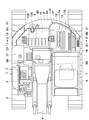
- FIG. 1 is a front view showing a hydraulic excavator according to an embodiment of the present invention. It is a top view which expands and shows the hydraulic shovel of FIG. It is the external appearance perspective view which looked at the upper turning body from the right rear side. It is the external appearance perspective view which looked at the upper turning body of the state which opened the heat exchanger cover from the same position as FIG.
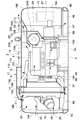
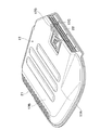
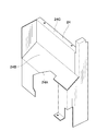
- FIG. 5 is an enlarged cross-sectional view of the upper swing body viewed from an arrow VV direction in FIG. 2. It is an external appearance perspective view which expands and shows a heat exchanger cover. It is an external appearance perspective view which expands and shows a firewall and a baffle plate in the assembled state. It is an external appearance perspective view which shows the firewall in FIG. 7 alone. It is an external appearance perspective view which shows the baffle plate in FIG. 7 alone.
- reference numeral 1 denotes a crawler hydraulic excavator as a construction machine.
- the hydraulic excavator 1 is mounted on a self-propelled lower traveling body 2 and on the lower traveling body 2 so as to be turnable.
- 2 is constituted roughly by an upper swing body 3 constituting a vehicle body and a work device 4 provided on the front side of the upper swing body 3 so as to be able to move up and down and performing excavation work of earth and sand.
- the revolving frame 5 is a turning frame as a body frame constituting a part of the upper turning body 3, and the turning frame 5 is formed as a support structure. Then, as shown in FIG. 5, the revolving frame 5 is provided with a bottom plate 5A made of a thick steel plate or the like extending in the front and rear directions, and a standing space on the bottom plate 5A.
- Left and right vertical plates 5B extending in the front and rear directions, and left and right left and right side frames 5D and 5D arranged at intervals on the left and right sides of the vertical plates 5B and extending in the front and rear directions,
- the base end side is fixed to the bottom plate 5A and the vertical plate 5B and extends in the left and right directions, and a plurality of extension beams 5E for supporting the left and right side frames 5C and 5D at the distal end side, the bottom plate 5A and the side frame
- a plurality of undercovers 5F provided between 5C and 5D are roughly configured.
- the working device 4 is attached to the revolving frame 5 in front of each vertical plate 5 ⁇ / b> B so as to move up and down.
- a cab mounted on the left front side of the revolving frame 5 on the side of the work device 4, and the cab 6 is used by an operator.
- a driver's seat 7 on which an operator is seated, a travel operation lever, a work operation lever, and the like (all not shown).
- the counterweight 8 is a counterweight attached to the rear end of the revolving frame 5, and this counterweight 8 is formed as an arcuate heavy object in order to balance the weight with the work device 4. More specifically, as shown in FIGS. 3 and 4, the counterweight 8 includes a central weight portion 8 ⁇ / b> A that is located in the center portion in the left and right directions and protrudes upward and has a high height dimension, and the central weight portion 8 ⁇ / b> A.
- the left and right side weight portions 8B and 8C are curved toward the front side while extending in the left and right directions.
- the left and right side weight portions 8B and 8C are provided with a low height near the lower side of the center weight portion 8A, so that the central portion of the overall shape of the counterweight 8 protrudes upward. It is formed in a mountain shape. Further, the central weight portion 8A has an upper surface 8D that is substantially the same height as an engine cover 15 described later, and a rear end side of the heat exchanger cover 17 is disposed on the upper side.
- Reference numeral 9 denotes an engine which is one of the mounted devices provided on the rear side of the turning frame 5, and the engine 9 is mounted on the front side of the counterweight 8 in a horizontally placed state extending in the left and right directions. ing. Further, as shown in FIG. 5, the engine 9 is provided with an output shaft 9A whose axis is in the left and right directions. A cooling fan 12, a generator (not shown), etc., which will be described later, are connected to the output shaft 9A via a belt 9B so as to be rotationally driven. On the other hand, a hydraulic pump 11 that discharges hydraulic oil as pressure oil by being driven by an output shaft 9A is attached to one side of the engine 9 in the left and right directions (right side in the embodiment).
- the engine 9 is provided with a muffler device 10 for discharging exhaust gas to the outside.
- the muffler device 10 includes an exhaust pipe 10A connected to the exhaust side of the engine 9, and a substantially cylindrical muffler provided in the middle of the exhaust pipe 10A so as to extend forward and rearward on the upper right side of the engine 9.
- the device 10B and a bracket 10C for attaching the silencer 10B to the engine 9 are roughly configured.
- Numeral 12 is a suction type cooling fan attached to the engine 9 and located on the opposite side of the hydraulic pump 11 to the left and right (left side in the embodiment) across the engine 9.
- the cooling fan 12 is driven to rotate by the engine 9, thereby allowing external air to pass through the air inlet 21 of the heat exchanger cover 17 of the exterior cover 14 and the left side air inlet 20 of the left side door cover 18 which will be described later.
- the cooling air is sucked in, and the sucked cooling air is supplied to the heat exchanger 13 described later.
- a part of the cooling air that has warmed up after passing through the heat exchanger 13 is discharged to the outside through the exhaust port 22 of the heat exchanger cover 17, and the other cooling air flows around the engine 9 toward the right side.
- the air is discharged to the outside from the right exhaust port 23 of the engine cover 15 and the bottom side of the revolving frame 5.
- the heat exchanger 13 is a heat exchanger provided on the swivel frame 5 at the rear side of the cab 6.
- the heat exchanger 13 constitutes one of the mounted devices mounted on the revolving frame 5 and includes, for example, a radiator that cools engine cooling water, an oil cooler that cools hydraulic oil, and the like. Further, the heat exchanger 13 is located upstream of the cooling fan 12 between the cab 6 and the counterweight 8 with respect to the flow direction of the cooling air, that is, between the left side door cover 18 and the cooling fan 12 described later.
- the cooling fan 12 is provided so as to face the cooling fan 12.
- the periphery of the heat exchanger 13 is surrounded by a rectifying support frame 13A, and a heat exchanger is sealed by sealing an upper portion of the support frame 13A with a heat exchanger cover 17 described later.
- a seal member 13B for preventing the warm air that has passed through the vessel 13 from flowing back is provided to extend in the forward and backward directions.
- Reference numeral 14 denotes an exterior cover provided on the revolving frame 5, and this exterior cover 14 covers the engine 9, the heat exchanger 13, and the like provided as the mounted equipment, and will be described later with an engine cover 15 and a heat exchanger cover 17.
- the left side door cover 18 and the right side door cover 19 are roughly configured.
- the hydraulic excavator 1 is configured as an ultra-small turning machine in which the upper turning body 3 can turn substantially within the vehicle width of the lower traveling body 2.
- the upper swing body 3 is formed compactly so that the counterweight 8 is disposed in front of the rear end of the lower traveling body 2 and the rear side of the counterweight 8 is substantially circular.
- the space for installing the heat exchanger 13 is reduced as the upper swing body 3 is formed in a small size. For this reason, in order to obtain a required cooling performance, it is necessary to form the heat exchanger 13 large on the upper side (higher on the upper side). Therefore, the upper position of the heat exchanger 13 protrudes above the installation position of the engine cover 15 constituting the exterior cover 14. As a result, the heat exchanger cover 17 covering the heat exchanger 13 is also swelled upward as compared with the engine cover 15.
- 15 is an engine cover that constitutes a part of the exterior cover 14, and the engine cover 15 is located on the rear side of the working device 4 and on the front side of the central weight portion 8 ⁇ / b> A of the counterweight 8 and covers the upper side of the engine 9.
- the engine cover 15 is fixedly attached in a state that cannot be opened and closed by means such as bolting or welding. More specifically, as shown in FIGS. 2 and 5, the engine cover 15 is positioned on the right side of the heat exchanger cover 17 so as to cover the upper side of the engine 9, the muffler device 10, and the hydraulic pump 11, and the counterweight. 8. It consists of the plate body extended substantially horizontally between the below-mentioned right side door cover 19 and the fuel tank 27. The engine cover 15 is disposed at substantially the same height as the central weight portion 8A of the counterweight 8.
- the engine cover 15 is formed as a large plate that covers the upper side of the engine 9, it is possible to secure a space for the operator to ride when performing inspection work, maintenance work, etc. of the heat exchanger 13 and the like. Can easily work on the engine cover 15. Further, the engine cover 15 is provided with a right exhaust port 23 to be described later for discharging the cooling air at a position away from the exhaust port 22 provided in the heat exchanger cover 17.
- the opening 16 is an opening formed at a position sandwiched between the counterweight 8 and the cab 6 between the engine cover 15 and a left side door cover 18 described later. As shown in FIGS. 4 and 5, the opening 16 is opened above the heat exchanger 13 and the belt 9 ⁇ / b> B of the engine 9 that require daily inspection work and periodic cleaning work. To do.
- Numeral 17 is a heat exchanger cover provided so as to be openable and closable above the heat exchanger 13 in order to close the opening 16.
- the heat exchanger cover 17 is arranged side by side with the engine cover 15 and the left side door cover 18 in the left and right directions, and constitutes a substantially trapezoidal lid that opens and closes the opening 16.
- the heat exchanger cover 17 is attached to the structure constituting the exterior cover 14 or the structure constituting the swivel frame 5 at the left end via a hinge or the like so as to be opened and closed.
- the heat exchanger cover 17 has a peripheral edge portion 17A that is in contact with the upper surface of the engine cover 15, the upper surface 8D of the central weight portion 8A of the counterweight 8, etc.
- a bulging upper surface 17B is formed by bulging upward from 17A. Thereby, the heat exchanger cover 17 can cover the large heat exchanger 13 on the upper side by the bulging upper surface 17B.
- the right end of the heat exchanger cover 17 is a vertical surface 17C extending substantially vertically downward from the bulging upper surface 17B toward the upper surface of the engine cover 15.
- the vertical surface 17C is for opening one exhaust port 22 to be described later in the horizontal direction.
- the vertical surface 17C has a rectangular shape elongated in the front and rear directions at a position slightly retracted from the right end of the bulging upper surface 17B. It is formed as a surface part.
- the heat exchanger cover 17 is provided with an opening / closing handle 17D located above the vertical surface 17C.
- an air inlet 21 to be described later is provided on the left side of the heat exchanger cover 17 so as to be located on the left side of the heat exchanger 13, and an exhaust port is provided on the right side of the heat exchanger cover 17 at the position of the vertical surface 17C. 22 is provided.
- the exhaust port 22 opens at a position spaced to the right of the cooling fan 12.
- Reference numeral 18 denotes a left side door cover as a left side cover constituting the left side of the exterior cover 14, and the left side door cover 18 has a structure in which, for example, the front part constitutes the structure or the revolving frame 5 constituting the exterior cover 14. It is attached to the body so that it can be opened and closed. When the left side door cover 18 is opened, inspection work, maintenance work, cleaning work, etc. of the heat exchanger 13, an air cleaner 26 described later, and the like can be performed.
- the left side door cover 18 is located facing the heat exchanger 13 and has a side surface portion 18A standing on the left side frame 5C, which is a side surface of the swivel frame 5, and an upper portion of the side surface portion 18A on the right side. And a curved surface portion 18B formed by bending in the direction. Further, a left side air inlet 20 described later is provided on the side surface portion 18A and the curved surface portion 18B of the left side door cover 18.
- the right side door cover 19 is a right side door cover as a right side cover constituting the right side of the exterior cover 14, and the right side door cover 19 includes a side surface portion 19A erected on the right side frame 5D of the revolving frame 5, It is constituted by a curved surface portion 19B formed by bending the upper portion of the side surface portion 19A leftward. And when the right side door cover 19 is opened, inspection work of the hydraulic pump 11, hydraulic equipment (not shown), etc. can be performed.
- Reference numeral 20 denotes a plurality of left side air inlets provided on the side surface 18A and the curved surface part 18B of the left side door cover 18, and the left side air inlets 20 have a plurality of slit-like openings and mesh-like openings. It is formed as. Each left side air inlet 20 sucks outside air as cooling air when the cooling fan 12 is driven to rotate.
- the air inlet 21 is an air inlet provided in the heat exchanger cover 17, and the air inlet 21 is on the left side door cover 18 side of the bulging upper surface 17B, that is, on the upstream side of the heat exchanger 13 in the flow direction of cooling air. Is located. Further, the air inlet 21 of the heat exchanger cover 17 is formed as a slit-like opening arranged in a large number in the front and rear directions, almost like a part of the left side air inlet 20. And the air inlet 21 sucks external air as cooling air when the cooling fan 12 is rotationally driven, like the left side air inlets 20.
- Reference numeral 22 denotes one exhaust port provided in the heat exchanger cover 17.
- the exhaust port 22 is provided on the right side of the engine cover 15 opposite to the intake port 21, that is, on the vertical surface 17 ⁇ / b> C of the heat exchanger cover 17. It has been.
- the exhaust port 22 is formed as a large number of grid-like openings arranged on the vertical surface 17C.
- the exhaust port 22 is provided on the vertical surface 17C to discharge the cooling air that has passed through the heat exchanger 13 in the horizontal direction on the engine cover 15.
- the exhaust port 22 provided in the small heat exchanger cover 17 is close to the intake port 21.
- the exhaust port 22 opens to the right side of the cooling fan 12 and can discharge the cooling air in the horizontal direction along the upper surface of the engine cover 15.
- the cooling air warmed after passing through the heat exchanger 13 can be discharged in a direction away from the intake port 21 and the like, and the warm air discharged from the exhaust port 22 is prevented from being sucked into the intake port 21 again. can do.
- the operating sound (noise) of the engine 9 does not leak directly from the exhaust port 22 that opens sideways, but on the bulging upper surface 17B of the heat exchanger cover 17. A part of the operating sound that collided leaks from the exhaust port 22. Further, the sideways exhaust port 22 can reduce the intrusion of rainwater, dust and the like into the exterior cover 14, and mud etc. are difficult to accumulate and can prevent clogging.
- the cooling air discharged from the right exhaust port 23 by the wind force can be pressed to the right side. Thereby, the cooling air discharged from the right exhaust port 23 can be prevented from being sucked into the intake ports 20 and 21 again.
- the right exhaust port 23 is a right exhaust port as the other exhaust port provided on the right side of the engine cover 15.
- the right exhaust port 23 is disposed at a position on the right side from the exhaust port 22 provided in the heat exchanger cover 17 and arranged side by side in the left and right directions, and discharges cooling air that has passed around the engine 9. It is. For this reason, the right exhaust port 23 is disposed above the hydraulic pump 11 on the right side of the engine 9.
- the right exhaust port 23 is greatly separated in the left and right directions with respect to the respective intake ports 20 and 21, and the cooling air is inclined diagonally upward to the right by a second inclined plate 25 ⁇ / b> C of the air guide plate 25 described later. Therefore, it is possible to prevent the circulation of the exhausted cooling air from the intake ports 20 and 21.
- firewall 24 that shields between the engine 9 and the hydraulic pump 11 to prevent the hydraulic oil from scattering to the engine 9 side.
- the firewall 24 is a firewall provided in the exterior cover 14, and the firewall 24 blocks between the engine 9 and the hydraulic pump 11.
- the firewall 24 is formed as a structure having strength against vibration, bending, and the like by, for example, bending a plurality of steel plates and fixing them together.
- a notch opening 24A is formed below the firewall 24 so as to straddle the mounting base of the hydraulic pump 11 with respect to the engine 9, and the upper side of the notch opening 24A is a muffler device. It is a recessed step portion 24B that is retracted to accommodate ten silencers 10B.
- a mounting portion 24C for mounting a wind guide plate 25 described later is formed at the upper end portion of the recessed step portion 24B.
- the lower portion of the firewall 24 is attached to the vertical plate 5B of the revolving frame 5, and the upper portion is attached to the engine cover 15 or the like via the air guide plate 25.
- the firewall 24 can prevent the leaked hydraulic oil from scattering to the engine 9 side even when the hydraulic oil leaks around the hydraulic pump 11, and can prevent a fire or the like. .
- the air guide plate 25 is a wind guide plate provided on the upper part of the firewall 24 so as to cover the silencer 10B of the muffler device 10.
- the air guide plate 25 guides the cooling air that has passed around the engine 9 toward the right exhaust port 23 of the engine cover 15, avoiding the silencer 10 ⁇ / b> B of the muffler device 10.
- the air guide plate 25 is formed, for example, by bending a steel plate. As shown in FIGS. 7 and 9, the air guide plate 25 has a bowl-shaped main body portion 25A and a left side from the main body portion 25A to guide the cooling air upward.
- a first inclined plate 25B extending downward and a second inclined plate 25C extending upward from the main body 25A toward the right side in order to guide the cooling air to the right exhaust port 23 of the engine cover 15. Has been.
- the air guide plate 25 can guide the cooling air to the right exhaust port 23 of the engine cover 15 and discharge it to the outside so as to avoid the firewall 24 that obstructs the flow of the cooling air. Can be efficiently cooled. Further, since the portion of the air guide plate 25 connected to the right exhaust port 23 is the second inclined plate 25C, the cooling air can be discharged obliquely upward to the right by the second inclined plate 25C. Wind can be separated from each inlet 20,21.
- the air guide plate 25 is disposed at a position that covers the silencer 10B of the muffler device 10 from the upper side, the silencer 10B that becomes an obstacle in the exterior cover 14 is avoided, and cooling air is supplied to the engine cover 15. It is possible to discharge smoothly from the right exhaust port 23. Further, the air guide plate 25 can block the noise generated in the muffler device 10 and can reduce the volume during operation.
- Reference numeral 26 denotes an air cleaner disposed between the heat exchanger 13 and the left side door cover 18.
- the air cleaner 26 is connected to the intake side of the engine 9 and supplies clean air to the engine 9. It is.
- a fuel tank 27 is located on the front side of the hydraulic pump 11 and is provided on the revolving frame 5. The fuel tank 27 stores fuel to be supplied to the engine 9.
- the hydraulic excavator 1 according to the present embodiment has the above-described configuration. Next, the operation of the hydraulic excavator 1 will be described.
- the operator gets on the cab 6 and sits in the driver's seat 7.
- the lower traveling body 2 can be driven to move the hydraulic excavator 1 forward or backward.
- the operator seated on the driver's seat 7 can perform work such as excavation of earth and sand by operating the operation lever for working to raise and lower the working device 4.
- the cooling fan 12 when the cooling fan 12 is driven to rotate, the external air is cooled via the left side intake ports 20 provided in the left side door cover 18 of the exterior cover 14 and the intake ports 21 provided in the heat exchanger cover 17. Inhaled as wind, this cooling wind can be supplied to the heat exchanger 13 to cool fluid such as engine coolant and hydraulic oil.
- the other cooling air flows around the engine 9 toward the right side, and a part thereof is discharged to the outside from the right exhaust port 23 provided in the engine cover 15.
- the air guide plate 25 provided on the firewall 24 sends the cooling air to the right side exhaust of the engine cover 15 so as to avoid the firewall 24 and the silencer 10B of the muffler device 10 that obstruct the flow of the cooling air. It can be led to the mouth 23 and discharged outside.
- the air guide plate 25 since the air guide plate 25 has a portion that is connected to the right exhaust port 23 as the second inclined plate 25C, the cooling air is discharged obliquely upward and rightward from the right exhaust port 23 along the angle of the second inclined plate 25C. can do.
- the right exhaust port 23 is arranged at a position aligned with the exhaust port 22 of the heat exchanger cover 17 in the left and right directions. As a result, the cooling air discharged from the exhaust port 23 is pressed to the right by the wind of the cooling air discharged from the one exhaust port 22 in the horizontal direction, and flows in a direction away from the intake ports 20, 21. Suction can be reliably prevented.
- the remaining cooling air that has circulated around the engine 9 toward the right side is discharged to the outside through an opening provided in the under cover 5F of the revolving frame 5.
- the heat exchanger cover 17 of the exterior cover 14 is provided with the intake port 21 that is located on the left side and sucks outside air as cooling air, and on the right side opposite to the intake port 21.
- An exhaust port 22 for discharging the cooling air that has passed through the heat exchanger 13 is provided, and the exhaust port 22 is configured to discharge the cooling air in the horizontal direction along the upper surface of the engine cover 15. Therefore, since the warm cooling air that has passed through the heat exchanger 13 can be discharged horizontally along the upper surface of the engine cover 15 from the exhaust port 22 provided in the heat exchanger cover 17, the warm cooling air is The heat exchanger cover 17 can be discharged in a direction away from the inlet 21 of the heat exchanger cover 17.
- the intake port 21 and the exhaust port 22 are provided in the small heat exchanger cover 17 and the intake port 21 and the exhaust port 22 are close to each other, the warm cooling air exhausted from the exhaust port 22 can be 21 can be prevented from being sucked again.
- the inlet 21 can supply the cooled cooling air to the heat exchanger 13, and the cooling efficiency of the fluid such as engine cooling water and hydraulic oil by the heat exchanger 13 can be improved.
- the exhaust port 22 is provided on the vertical surface 17C of the heat exchanger cover 17, the exhaust port 22 can be opened sideways, and the operating sound of the engine 9 is directed upward from the exhaust port 22. Direct leakage can be prevented, and the quietness during work can be improved. Further, the sideways exhaust port 22 can reduce the intrusion of rainwater, dust and the like into the outer cover 14, and can also prevent clogging due to mud and the like.
- the exhaust port 22 provided in the heat exchanger cover 17 and the exhaust port 23 provided in the engine cover 15 are arranged side by side in the left and right directions, one of the exhaust ports 22 supplies cooling air.
- the cooling air discharged from the other exhaust port 23 can be pressed to the right side.
- the cooling air discharged from the right exhaust port 23 provided in the engine cover 15 flows in a direction away from the intake ports 20 and 21, and the re-suction of the cooling air can be prevented more reliably.
- the firewall 24 that shields between the engine 9 and the hydraulic pump 11 in the exterior cover 14 is provided, even if the hydraulic oil leaks around the hydraulic pump 11, the leaked hydraulic oil remains on the engine 9 side. Can be prevented, fire can be prevented, and reliability can be improved.
- the firewall 24 is provided with an air guide plate 25 that guides the cooling air that has passed around the engine 9 toward the right exhaust port 23 provided in the engine cover 15.
- the air guide plate 25 guides the cooling air that has passed around the engine 9 toward the right exhaust port 23 provided in the engine cover 15.
- the air guide plate 25 is disposed at a position that covers the silencer 10B of the muffler device 10 from the upper side, the silencer 10B that becomes an obstacle in the exterior cover 14 is avoided, and the cooling air is supplied to the right exhaust port 23. Can be discharged smoothly. Further, the air guide plate 25 can block the noise generated in the muffler device 10 and can reduce the volume during operation.
- the counterweight 8 includes a central weight portion 8A having a high height dimension, and left and right side weight portions having a low height dimension which are curved leftward and rightward while extending from the central weight portion 8A to the left and right. Since it is constituted by 8B and 8C, the counterweight 8 can be increased in weight in a limited space. Further, the rear side of the heat exchanger cover 17 can be arranged using the upper surface side of the central weight portion 8A of the counterweight 8.
- a cooling fan may be provided separately from the engine, and may be rotationally driven using an electric motor, a hydraulic motor, or the like to supply cooling air to the heat exchange device.
- the engine cover 15 is described as being fixedly attached in a state where it cannot be opened and closed, it may be configured so that it can be opened and closed by removing bolts or the like or can be removed.
- left side door cover 18 and the right side door cover 19 constituting the exterior cover 14 are not limited to covers that can be opened and closed, and may be fixed side covers that do not open and close. Further, the left and right side door covers 18 and 19 may have an openable / closable cover on one side and a fixed cover on the other side.
- the explanation has been given by taking the hydraulic excavator 1 provided with the crawler type lower traveling body 2 as an example of the construction machine.
- the present invention is not limited to this, and may be applied to, for example, a hydraulic excavator provided with a wheel-type lower traveling body. Besides, it can be widely applied to other construction machines such as wheel loaders, dump trucks, lift trucks and the like.
Abstract
An air suction opening (21) is formed in the left side, which is the upstream of cooling air, of a heat exchanger cover (17) for covering above a heat exchanger (13), and one air discharge opening (22) for discharging cooling air having passed through the heat exchanger (13) is formed in the right side, the side opposite the air suction opening (21). The air discharge opening (22) is adapted to discharge the cooling air in the horizontal direction toward an engine cover (15). The engine cover (15) is provided with the other air discharge opening (23) located at a position opposed in the left-right direction to the one air discharge opening (22). Cooling air warmed when passing through the heat exchanger (13) can be discharged in the horizontal direction from the air discharge opening (22) in the heat exchanger cover (17) toward the air discharge opening (23) in the engine cover (15). As a result, the cooling air discharged from the air discharge opening (22) flows away in the direction toward the side opposite the air suction opening (21), and this prevents the warmed air from being sucked again into the air suction opening (21).
Description
本発明は、例えば油圧ショベル、油圧クレーン、ホイールローダ等の建設機械に関し、特に、エンジン等の搭載機器を覆う外装カバーを備えた建設機械に関する。
The present invention relates to a construction machine such as a hydraulic excavator, a hydraulic crane, or a wheel loader, and more particularly to a construction machine provided with an exterior cover that covers a mounted device such as an engine.
一般に、建設機械としての油圧ショベルは、自走可能な下部走行体と、該下部走行体上に旋回可能に搭載された上部旋回体と、該上部旋回体の前側に俯仰動可能に設けられた作業装置とにより大略構成されている。
In general, a hydraulic excavator as a construction machine is provided with a self-propelled lower traveling body, an upper revolving body that is turnably mounted on the lower traveling body, and a front-rear side of the upper revolving body that can be raised and lowered. It is roughly constituted by a working device.
また、上部旋回体は、支持構造体をなす旋回フレームと、該旋回フレームの後側に搭載され、油圧ポンプを駆動するエンジンと、該エンジンによって回転駆動される冷却ファンと、該冷却ファンに対面して設けられたラジエータ、オイルクーラ等の熱交換器と、前記エンジン、冷却ファン、熱交換器等の搭載機器を覆うために前記旋回フレーム上に設けられた外装カバーとにより大略構成されている。
In addition, the upper swing body is mounted on the rear side of the swing frame that forms the support structure, the engine that drives the hydraulic pump, the cooling fan that is driven to rotate by the engine, and the cooling fan. And a heat exchanger such as a radiator and an oil cooler, and an exterior cover provided on the swivel frame to cover equipment mounted on the engine, a cooling fan, a heat exchanger, and the like. .
ここで、外装カバーは、各搭載機器の上側に水平方向に延びて設けられた上面板と、該上面板の左,右両端から旋回フレームに向け下向きに延びた左,右の側面板とにより構成され、前記上面板には、エンジン、熱交換器等を点検、整備するための大きな開口が設けられている。
Here, the exterior cover is composed of an upper surface plate provided horizontally extending above each mounted device, and left and right side plates extending downward from the left and right ends of the upper surface plate toward the swivel frame. The upper surface plate is provided with a large opening for inspecting and maintaining an engine, a heat exchanger, and the like.
これに伴い、上面板には、前記開口を閉塞するために開閉可能なエンジンカバーが取付けられ、該エンジンカバーは、熱交換器から油圧ポンプまでを覆うように左,右方向に大きく形成されている。また、エンジンカバーの左側には、冷却ファンを回転駆動したときに、外部から熱交換器に向け冷却風を吸込むための吸気口が設けられ、右側には、熱交換器、冷却ファンを通過した冷却風を外部に排出するための排気口が設けられている(特許文献1:特開2000-303497号公報、特許文献2:実開平7-30321号公報参照)。
Along with this, an engine cover that can be opened and closed is attached to the top plate so as to close the opening, and the engine cover is formed large in the left and right directions so as to cover from the heat exchanger to the hydraulic pump. Yes. In addition, an intake port is provided on the left side of the engine cover for sucking cooling air from the outside to the heat exchanger when the cooling fan is driven to rotate, and the heat exchanger and the cooling fan are passed on the right side. Exhaust ports for discharging cooling air to the outside are provided (see Patent Document 1: Japanese Patent Laid-Open No. 2000-303497, Patent Document 2: Japanese Utility Model Laid-Open No. 7-30321).
ところで、上述した各特許文献による油圧ショベルでは、外装カバーの上面板にエンジンカバーを開閉可能に取付け、このエンジンカバーに冷却風の吸気口と排気口とを設ける構成としている。
By the way, in the hydraulic excavator according to each of the above-mentioned patent documents, the engine cover is attached to the top plate of the exterior cover so that it can be opened and closed, and the engine cover is provided with an intake port and an exhaust port for cooling air.
ここで、エンジン等の点検作業、整備作業等を行う場合には、エンジンカバーを開き、作業者が上面板に乗って作業を行う。しかし、上面板に大きな開口を設け、この開口をエンジンカバーで覆う構成とした場合、上部旋回体がコンパクトに形成されている小型の油圧ショベルでは、上面板に作業者が乗るスペースを確保することができず、メンテナンス作業の作業性が悪くなるという問題がある。
Here, when carrying out inspection work, maintenance work, etc. of the engine etc., the engine cover is opened and the worker gets on the top plate. However, when a large opening is provided in the top plate and this opening is covered with the engine cover, a small excavator in which the upper swing body is compactly formed must secure a space for the operator to get on the top plate. There is a problem that the workability of the maintenance work is deteriorated.
そこで、小型の油圧ショベルでは、定期的な点検作業、清掃作業等を必要とする熱交換器の上側だけに小さな開口部を設け、この熱交換器だけを覆うように上面板に熱交換器カバーを開閉可能に取付けることが考えられている。この場合には、上面板に作業者が乗って作業するスペースを確保することができる。
Therefore, in a small hydraulic excavator, a small opening is provided only on the upper side of the heat exchanger that requires periodic inspection work, cleaning work, etc., and a heat exchanger cover is provided on the top plate so as to cover only this heat exchanger. It is considered that the door can be opened and closed. In this case, it is possible to secure a space for the worker to get on the top plate and work.
しかし、熱交換器の上側を小さな熱交換器カバーで覆う構成とした場合、この熱交換器カバーに設けた吸気口と排気口とが接近することになる。このために、排気口から排出された暖まった空気を吸気口から再度吸込んでしまうサーキュレーションを生じてしまい、熱交換器による流体の冷却効率が低下するという問題がある。
However, when the upper side of the heat exchanger is covered with a small heat exchanger cover, the intake port and the exhaust port provided in the heat exchanger cover come close to each other. For this reason, there occurs a circulation in which the warm air discharged from the exhaust port is sucked again from the intake port, and there is a problem that the cooling efficiency of the fluid by the heat exchanger is lowered.
本発明は上述した従来技術の問題に鑑みなされたもので、本発明の目的は、小さな熱交換器カバーに吸気口と排気口とを設けた場合でも、排気口から排出する冷却風を吸気口から離れた場所に排出でき、暖気の再吸込みを防止して熱交換器による冷却効率を向上できるようにした建設機械を提供することにある。
The present invention has been made in view of the above-described problems of the prior art, and an object of the present invention is to provide cooling air discharged from the exhaust port even when the intake port and the exhaust port are provided in a small heat exchanger cover. It is an object of the present invention to provide a construction machine that can be discharged to a place away from the vehicle and can improve the cooling efficiency by a heat exchanger by preventing re-suction of warm air.
また、本発明の他の目的は、冷却ファンによって外装カバー内を流れる冷却風を、エンジンカバーに設けられた排気口に向けて導くことにより、外装カバー内で冷却風を効率よく流通できるようにした建設機械を提供することにある。
Another object of the present invention is to guide the cooling air flowing in the exterior cover by the cooling fan toward the exhaust port provided in the engine cover so that the cooling air can be efficiently distributed in the exterior cover. Is to provide a construction machine.
(1).本発明による建設機械は、支持構造体をなし前側に作業装置が取付けられる車体フレームと、該車体フレームの後側に設けられたカウンタウエイトと、該カウンタウエイトの前側に位置して前記車体フレーム上に搭載されたエンジンと、該エンジンの左,右方向一側に設けられ該エンジンによって駆動される油圧ポンプと、該油圧ポンプとは左,右方向の反対側に位置して該エンジンに付設され外部から冷却風を吸込む冷却ファンと、冷却風の流れ方向に対して該冷却ファンよりも上流側に位置し該冷却ファンと対面して設けられた熱交換器と、前記エンジン、油圧ポンプ、熱交換器を含む搭載機器を覆うために前記車体フレーム上に設けられた外装カバーとからなる。
(1). A construction machine according to the present invention includes a vehicle body frame having a support structure and a work device attached to the front side, a counterweight provided on the rear side of the vehicle body frame, and a front side of the counterweight, Mounted on the engine, a hydraulic pump provided on one side of the engine in the left and right directions, and driven by the engine, and the hydraulic pump located on the opposite side in the left and right directions and attached to the engine A cooling fan that sucks cooling air from the outside, a heat exchanger that is located upstream of the cooling fan in the flow direction of the cooling air and is provided facing the cooling fan, the engine, the hydraulic pump, the heat It comprises an exterior cover provided on the vehicle body frame to cover the mounted equipment including the exchanger.
そして、上述した課題を解決するために、本発明が採用する構成の特徴は、前記外装カバーは、前記エンジンの上方に設けられたエンジンカバーと、該エンジンカバーと左,右方向に並んで前記熱交換器の上方に開閉可能に設けられると共に該エンジンカバーの上面に比較して上方に膨出した膨出上面を有する熱交換器カバーと、前記熱交換器と対面し前記車体フレームの側面に位置して設けられた側面カバーとを備え、前記熱交換器カバーには、前記側面カバー側に位置して外気を冷却風として吸込む吸気口と、前記エンジンカバー側に位置して前記熱交換器を通過した冷却風を前記エンジンカバー上で水平方向に排出する一方の排気口とを設け、前記エンジンカバーには、前記熱交換器カバーに設けられた前記一方の排気口から離れた位置で冷却風を排出する他方の排気口を設ける構成としたことにある。
In order to solve the above-described problem, the configuration of the present invention employs a configuration in which the exterior cover includes an engine cover provided above the engine, and the engine cover aligned in the left and right directions. A heat exchanger cover provided on the heat exchanger so as to be openable and closable and having a bulging upper surface that bulges upward compared to the upper surface of the engine cover, and facing the heat exchanger on the side surface of the vehicle body frame A side cover provided on the side of the heat exchanger, the heat exchanger cover being positioned on the side of the side cover and sucking outside air as cooling air; and the heat exchanger positioned on the side of the engine cover. One exhaust port for discharging the cooling air that has passed through the engine cover in a horizontal direction on the engine cover is provided, and the engine cover is separated from the one exhaust port provided in the heat exchanger cover In that a configuration in which the other exhaust port for discharging the cooling air in location.
この構成により、熱交換器を通過して暖まった冷却風は、熱交換器カバーに設けられた一方の排気口からエンジンカバーの上面に沿って水平方向に排出することができる。これにより、暖まった冷却風は、熱交換器カバーの吸込口と反対側に離れる方向に排出できる。
With this configuration, the cooling air warmed after passing through the heat exchanger can be discharged in the horizontal direction along the upper surface of the engine cover from one exhaust port provided in the heat exchanger cover. Thereby, the warm cooling air can be discharged in a direction away from the suction port of the heat exchanger cover.
この結果、小さな熱交換器カバーに吸気口と排気口を設け、この吸気口と排気口とが接近している構造でも、排気口から排出した暖気が吸気口に再度吸込まれるのを防止できるから、吸気口は冷えた冷却風を熱交換器に供給することができ、熱交換器による流体の冷却効率を向上することができる。
As a result, even with a structure in which an intake port and an exhaust port are provided in a small heat exchanger cover and the intake port and the exhaust port are close to each other, warm air exhausted from the exhaust port can be prevented from being sucked into the intake port again. Therefore, the intake port can supply the cooled cooling air to the heat exchanger, and the cooling efficiency of the fluid by the heat exchanger can be improved.
(2).この場合、本発明によると、前記熱交換器カバーは、前記膨出上面から前記エンジンカバーの上面に向けて下側にほぼ垂直に延びた垂直面を有し、前記一方の排気口は該垂直面に設ける構成としたことにある。
(2). In this case, according to the present invention, the heat exchanger cover has a vertical surface extending substantially vertically downward from the bulging upper surface toward the upper surface of the engine cover, and the one exhaust port has the vertical surface. The configuration is that it is provided on the surface.
この構成により、一方の排気口は熱交換器カバーの垂直面に横向き開口として設けることができるから、エンジンの作動音(騒音)が排気口から直接的に外部に漏れるのを防止でき、作業時の静粛性を高めることができる。また、横向きの排気口は、外装カバー内への雨水、塵埃等の浸入を少なくでき、さらに、泥等による目詰まりも防止することができる。
With this configuration, one exhaust port can be provided as a lateral opening on the vertical surface of the heat exchanger cover, so that engine operating noise (noise) can be prevented from leaking directly from the exhaust port to the outside. Can improve the silence. Further, the sideways exhaust port can reduce the intrusion of rainwater, dust and the like into the exterior cover, and can also prevent clogging due to mud and the like.
(3).本発明によると、前記熱交換器カバーに設けられた一方の排気口と前記エンジンカバーに設けられた他方の排気口とは、左,右方向に並べて配置する構成としたことにある。これにより、他方の排気口から排出された冷却風は、一方の排気口から水平方向に排出された冷却風の風力によって吸気口から離れる方向に流し、再度の吸込みを確実に防止することができる。
(3) According to the present invention, the one exhaust port provided in the heat exchanger cover and the other exhaust port provided in the engine cover are arranged side by side in the left and right directions. is there. Thereby, the cooling air discharged from the other exhaust port flows in a direction away from the intake port by the wind of the cooling air discharged in the horizontal direction from the one exhaust port, and can be reliably prevented from being sucked again. .
(4).本発明によると、前記外装カバー内には、前記エンジンと油圧ポンプとの間を遮るファイヤウォールを設け、該ファイヤウォールには、前記エンジンの周囲を通過した冷却風を前記他方の排気口に向けて導く導風板を設ける構成としたことにある。これにより、油圧ポンプの周囲で油圧漏れが生じた場合でも、漏れ出た作動油がエンジン側に飛散するのを防止でき、火災等を未然に防ぐことができる。
(4) According to the present invention, a fire wall is provided in the exterior cover to block between the engine and the hydraulic pump, and cooling air that has passed around the engine is passed through the fire wall to the other cover. In this configuration, an air guide plate is provided to guide the exhaust port. As a result, even when a hydraulic leak occurs around the hydraulic pump, it is possible to prevent the leaked hydraulic oil from scattering to the engine side and to prevent a fire or the like.
しかも、ファイヤウォールには、エンジンの周囲を通過した冷却風をエンジンカバーに設けた他方の排気口に向けて導く導風板を設けているから、冷却風の流通の障害となるファイヤウォールを設けた場合でも、導風板により排出すべき冷却風を他方の排気口に向けてスムーズに流通させることができ、各部を効率よく冷却することができる。
In addition, the firewall is provided with a wind guide plate that guides the cooling air that has passed around the engine toward the other exhaust port provided in the engine cover, so that a firewall that obstructs the flow of the cooling air is provided. Even in this case, the cooling air to be discharged by the air guide plate can be smoothly circulated toward the other exhaust port, and each part can be efficiently cooled.
(5).本発明によると、前記導風板は、前記エンジンの排気ガスを排出するマフラ装置を上側から覆う位置に配設したことにある。これにより、外装カバー内で障害物となるマフラ装置を避け、冷却風を他方の排気口からスムーズに排出することができる。また、導風板は、マフラ装置で生じる騒音を遮ることができ、稼動時の音量を小さくすることができる。
(5) According to the present invention, the air guide plate is disposed at a position covering the muffler device for discharging the exhaust gas of the engine from above. Thereby, the muffler device which becomes an obstacle in the exterior cover can be avoided, and the cooling air can be smoothly discharged from the other exhaust port. Further, the air guide plate can block noise generated in the muffler device, and can reduce the volume during operation.
(6).本発明によると、前記カウンタウエイトは、高さ寸法が高い中央ウエイト部と、該中央ウエイト部から左,右方向に延びつつ前側に向けて湾曲した左,右の側方ウエイト部とにより構成し、前記熱交換器カバーの後側は前記中央ウエイト部の上面側に配置する構成としたことにある。
(6) According to the present invention, the counterweight includes a center weight portion having a high height, and left and right side weight portions that are curved toward the front side while extending left and right from the center weight portion. And the rear side of the heat exchanger cover is arranged on the upper surface side of the central weight portion.
これにより、カウンタウエイトを限られたスペースで大きな重量とすることができる。また、熱交換器カバーの後側をカウンタウエイトの中央ウエイト部の上面側を利用して配置することができる。
This makes it possible to increase the weight of the counterweight in a limited space. Further, the rear side of the heat exchanger cover can be arranged using the upper surface side of the central weight portion of the counterweight.
(7).本発明によると、自走可能な下部走行体と、該下部走行体上に旋回可能に搭載された上部旋回体と、該上部旋回体の前側で左,右方向の中央部に俯仰動可能に設けられた前記作業装置とからなり、前記車体フレームは前記上部旋回体を構成し、前側に前記作業装置が取付けられた旋回フレームであり、前記旋回フレームには前記作業装置の側方に位置してオペレータが着座する運転席を有するキャブを設け、前記エンジンは前記カウンタウエイトの前側に位置して前記旋回フレーム上を左,右方向に延びる横置きに配置し、前記熱交換器は前記キャブの後側で前記エンジンと側面カバーとの間に配置する構成としたことにある。
(7). According to the present invention, a self-propelled lower traveling body, an upper revolving body that is turnably mounted on the lower traveling body, and a left and right central portion on the front side of the upper revolving body. The vehicle body frame is a revolving frame in which the vehicle body frame constitutes the upper revolving body and the work device is attached to the front side, and the revolving frame is on the side of the work device. A cab having a driver's seat on which the operator is seated is provided, the engine is positioned on the front side of the counterweight, and is placed horizontally on the swivel frame so as to extend in the left and right directions, and the heat exchanger Is configured to be disposed between the engine and the side cover on the rear side of the cab.
1 油圧ショベル(建設機械)
2 下部走行体(車体)
3 上部旋回体(車体)
4 作業装置
5 旋回フレーム(車体フレーム)
6 キャブ
7 運転席
8 カウンタウエイト
8A 中央ウエイト部
8B 左側方ウエイト部
8C 左側方ウエイト部
8D 上面
9 エンジン(搭載機器)
10 マフラ装置
10A 排気管
10B 消音器
11 油圧ポンプ
12 冷却ファン
13 熱交換装置(搭載機器)
14 外装カバー
15 エンジンカバー
16 開口
17 熱交換器カバー
17A 周縁部
17B 膨出上面
17C 垂直面
18 左側面ドアカバー(左側面カバー)
19 右側面ドアカバー(右側面カバー)
20 左側面吸気口
21 吸気口
22 一方の排出口
23 右側排気口(他方の排気口)
24 ファイヤウォール
25 導風板 1 Excavator (construction machine)
2 Lower traveling body (car body)
3 Upper swing body (car body)
4 Workingdevice 5 Turning frame (body frame)
6Cab 7 Driver's seat 8 Counterweight 8A Center weight 8B Left side weight 8C Left side weight 8D Upper surface 9 Engine (equipment)
DESCRIPTION OFSYMBOLS 10 Muffler apparatus 10A Exhaust pipe 10B Silencer 11 Hydraulic pump 12 Cooling fan 13 Heat exchange apparatus (equipment installed)
14exterior cover 15 engine cover 16 opening 17 heat exchanger cover 17A peripheral edge 17B bulging upper surface 17C vertical surface 18 left side door cover (left side cover)
19 Right side door cover (right side cover)
20 Leftside intake port 21 Intake port 22 One exhaust port 23 Right side exhaust port (the other exhaust port)
24Firewall 25 Wind guide plate
2 下部走行体(車体)
3 上部旋回体(車体)
4 作業装置
5 旋回フレーム(車体フレーム)
6 キャブ
7 運転席
8 カウンタウエイト
8A 中央ウエイト部
8B 左側方ウエイト部
8C 左側方ウエイト部
8D 上面
9 エンジン(搭載機器)
10 マフラ装置
10A 排気管
10B 消音器
11 油圧ポンプ
12 冷却ファン
13 熱交換装置(搭載機器)
14 外装カバー
15 エンジンカバー
16 開口
17 熱交換器カバー
17A 周縁部
17B 膨出上面
17C 垂直面
18 左側面ドアカバー(左側面カバー)
19 右側面ドアカバー(右側面カバー)
20 左側面吸気口
21 吸気口
22 一方の排出口
23 右側排気口(他方の排気口)
24 ファイヤウォール
25 導風板 1 Excavator (construction machine)
2 Lower traveling body (car body)
3 Upper swing body (car body)
4 Working
6
DESCRIPTION OF
14
19 Right side door cover (right side cover)
20 Left
24
以下、本発明の実施の形態に係る建設機械として、クローラ式の油圧ショベルを例に挙げ、図1ないし図9に従って詳細に説明する。
Hereinafter, as a construction machine according to an embodiment of the present invention, a crawler type hydraulic excavator will be described as an example and described in detail with reference to FIGS.
図1において、1は建設機械としてのクローラ式の油圧ショベルで、該油圧ショベル1は、自走可能な下部走行体2と、該下部走行体2上に旋回可能に搭載され、該下部走行体2と共に車体を構成する上部旋回体3と、該上部旋回体3の前側に俯仰動可能に設けられ、土砂の掘削作業等を行なう作業装置4とにより大略構成されている。
In FIG. 1, reference numeral 1 denotes a crawler hydraulic excavator as a construction machine. The hydraulic excavator 1 is mounted on a self-propelled lower traveling body 2 and on the lower traveling body 2 so as to be turnable. 2 is constituted roughly by an upper swing body 3 constituting a vehicle body and a work device 4 provided on the front side of the upper swing body 3 so as to be able to move up and down and performing excavation work of earth and sand.
5は上部旋回体3の一部を構成する車体フレームとしての旋回フレームで、該旋回フレーム5は支持構造体として形成されている。そして、旋回フレーム5は、図5に示す如く、前,後方向に延びる厚肉な鋼板等からなる底板5Aと、該底板5A上に立設され、左,右方向の中央部に所定の間隔をもって前,後方向に延びた左,右の縦板5Bと、該各縦板5Bの左,右に間隔をもって配置され、前,後方向に延びた左サイドフレーム5C,右サイドフレーム5Dと、基端側が前記底板5A、縦板5Bに固着されて左,右方向に張出し、その先端側に左,右のサイドフレーム5C,5Dを支持する複数本の張出しビーム5Eと、底板5Aとサイドフレーム5C,5Dとの間に設けられた複数枚のアンダカバー5Fとにより大略構成されている。そして、図2に示すように、旋回フレーム5には、各縦板5Bの前側に作業装置4が俯仰動可能に取付けられている。
5 is a turning frame as a body frame constituting a part of the upper turning body 3, and the turning frame 5 is formed as a support structure. Then, as shown in FIG. 5, the revolving frame 5 is provided with a bottom plate 5A made of a thick steel plate or the like extending in the front and rear directions, and a standing space on the bottom plate 5A. Left and right vertical plates 5B extending in the front and rear directions, and left and right left and right side frames 5D and 5D arranged at intervals on the left and right sides of the vertical plates 5B and extending in the front and rear directions, The base end side is fixed to the bottom plate 5A and the vertical plate 5B and extends in the left and right directions, and a plurality of extension beams 5E for supporting the left and right side frames 5C and 5D at the distal end side, the bottom plate 5A and the side frame A plurality of undercovers 5F provided between 5C and 5D are roughly configured. As shown in FIG. 2, the working device 4 is attached to the revolving frame 5 in front of each vertical plate 5 </ b> B so as to move up and down.
6は作業装置4の側方となる旋回フレーム5の左前側に搭載されたキャブを示し、該キャブ6は、オペレータが搭乗するものである。また、キャブ6の内部には、オペレータが着座する運転席7、走行用の操作レバー、作業用の操作レバー等(いずれも図示せず)が配設されている。
6 indicates a cab mounted on the left front side of the revolving frame 5 on the side of the work device 4, and the cab 6 is used by an operator. Inside the cab 6 are disposed a driver's seat 7 on which an operator is seated, a travel operation lever, a work operation lever, and the like (all not shown).
8は旋回フレーム5の後端部に取付けられたカウンタウエイトで、このカウンタウエイト8は、作業装置4との重量バランスをとるために、円弧状をした重量物として形成されている。詳しく述べると、カウンタウエイト8は、図3、図4に示すように、左,右方向の中央部分に位置して上向きに突出した高さ寸法が高い中央ウエイト部8Aと、該中央ウエイト部8Aから左,右方向に延びつつ前側に向けて湾曲した左,右の側方ウエイト部8B,8Cとにより構成されている。
8 is a counterweight attached to the rear end of the revolving frame 5, and this counterweight 8 is formed as an arcuate heavy object in order to balance the weight with the work device 4. More specifically, as shown in FIGS. 3 and 4, the counterweight 8 includes a central weight portion 8 </ b> A that is located in the center portion in the left and right directions and protrudes upward and has a high height dimension, and the central weight portion 8 </ b> A. The left and right side weight portions 8B and 8C are curved toward the front side while extending in the left and right directions.
ここで、左,右の側方ウエイト部8B,8Cは、中央ウエイト部8Aの下側寄りに低い高さ寸法をもって設けられ、これにより、カウンタウエイト8の全体形状は中央部が上方に突出した山形状に形成されている。また、中央ウエイト部8Aは、その上面8Dが後述するエンジンカバー15とほぼ同じ高さ位置となり、その上側には熱交換器カバー17の後端側が配置されている。
Here, the left and right side weight portions 8B and 8C are provided with a low height near the lower side of the center weight portion 8A, so that the central portion of the overall shape of the counterweight 8 protrudes upward. It is formed in a mountain shape. Further, the central weight portion 8A has an upper surface 8D that is substantially the same height as an engine cover 15 described later, and a rear end side of the heat exchanger cover 17 is disposed on the upper side.
9は旋回フレーム5の後側に設けられた搭載機器の1つとなるエンジンを示し、該エンジン9は、カウンタウエイト8の前側に位置して左,右方向に延在する横置き状態に搭載されている。また、エンジン9には、図5に示す如く、軸線が左,右方向となる出力軸9Aが設けられている。この出力軸9Aには、ベルト9Bを介して後述の冷却ファン12、発電機(図示せず)等が回転駆動可能に接続されている。一方、エンジン9の左,右方向一側(実施の形態で右側)には、出力軸9Aで駆動されることにより、作動油を圧油として吐出する油圧ポンプ11が取付けられている。
Reference numeral 9 denotes an engine which is one of the mounted devices provided on the rear side of the turning frame 5, and the engine 9 is mounted on the front side of the counterweight 8 in a horizontally placed state extending in the left and right directions. ing. Further, as shown in FIG. 5, the engine 9 is provided with an output shaft 9A whose axis is in the left and right directions. A cooling fan 12, a generator (not shown), etc., which will be described later, are connected to the output shaft 9A via a belt 9B so as to be rotationally driven. On the other hand, a hydraulic pump 11 that discharges hydraulic oil as pressure oil by being driven by an output shaft 9A is attached to one side of the engine 9 in the left and right directions (right side in the embodiment).
さらに、エンジン9には、排気ガスを外部に排出するためのマフラ装置10が設けられている。そして、このマフラ装置10は、エンジン9の排気側に接続される排気管10Aと、該排気管10Aの途中でエンジン9の右側上部に前,後方向に延びて設けられた略円筒状の消音器10Bと、該消音器10Bをエンジン9に取付けるブラケット10Cとにより大略構成されている。
Furthermore, the engine 9 is provided with a muffler device 10 for discharging exhaust gas to the outside. The muffler device 10 includes an exhaust pipe 10A connected to the exhaust side of the engine 9, and a substantially cylindrical muffler provided in the middle of the exhaust pipe 10A so as to extend forward and rearward on the upper right side of the engine 9. The device 10B and a bracket 10C for attaching the silencer 10B to the engine 9 are roughly configured.
12はエンジン9を挟んで油圧ポンプ11と左,右方向の反対側(実施の形態では左側)に位置してエンジン9に付設された吸込み式の冷却ファンである。この冷却ファン12は、エンジン9によって回転駆動されることにより、後述する外装カバー14の熱交換器カバー17の吸気口21、左側面ドアカバー18の左側面吸気口20を介して外部の空気を冷却風として吸込み、この吸込んだ冷却風を後述の熱交換器13に供給するものである。そして、熱交換器13を通過して暖まった一部の冷却風は、熱交換器カバー17の排気口22から外部に排出され、その他の冷却風は、エンジン9の周囲を右側に向けて流通し、エンジンカバー15の右側排気口23、旋回フレーム5の底部側から外部に排出される。
Numeral 12 is a suction type cooling fan attached to the engine 9 and located on the opposite side of the hydraulic pump 11 to the left and right (left side in the embodiment) across the engine 9. The cooling fan 12 is driven to rotate by the engine 9, thereby allowing external air to pass through the air inlet 21 of the heat exchanger cover 17 of the exterior cover 14 and the left side air inlet 20 of the left side door cover 18 which will be described later. The cooling air is sucked in, and the sucked cooling air is supplied to the heat exchanger 13 described later. Then, a part of the cooling air that has warmed up after passing through the heat exchanger 13 is discharged to the outside through the exhaust port 22 of the heat exchanger cover 17, and the other cooling air flows around the engine 9 toward the right side. Then, the air is discharged to the outside from the right exhaust port 23 of the engine cover 15 and the bottom side of the revolving frame 5.
13はキャブ6の後側に位置して旋回フレーム5上に設けられた熱交換器である。この熱交換器13は、旋回フレーム5に搭載される搭載機器の1つをなすもので、例えばエンジン冷却水を冷却するラジエータ、作動油を冷却するオイルクーラ等により構成されている。また、熱交換器13は、キャブ6とカウンタウエイト8との間で、冷却風の流れ方向に対して冷却ファン12よりも上流側、即ち、後述の左側面ドアカバー18と冷却ファン12との間に位置して該冷却ファン12と対面するように設けられている。
13 is a heat exchanger provided on the swivel frame 5 at the rear side of the cab 6. The heat exchanger 13 constitutes one of the mounted devices mounted on the revolving frame 5 and includes, for example, a radiator that cools engine cooling water, an oil cooler that cools hydraulic oil, and the like. Further, the heat exchanger 13 is located upstream of the cooling fan 12 between the cab 6 and the counterweight 8 with respect to the flow direction of the cooling air, that is, between the left side door cover 18 and the cooling fan 12 described later. The cooling fan 12 is provided so as to face the cooling fan 12.
さらに、熱交換器13の周囲は、整流用の支持枠体13Aによって取囲まれ、該支持枠体13Aの上部には、後述する熱交換器カバー17との間をシールすることにより、熱交換器13を通過した暖気が還流するのを防止するシール部材13Bが前,後方向に延びて設けられている。
Further, the periphery of the heat exchanger 13 is surrounded by a rectifying support frame 13A, and a heat exchanger is sealed by sealing an upper portion of the support frame 13A with a heat exchanger cover 17 described later. A seal member 13B for preventing the warm air that has passed through the vessel 13 from flowing back is provided to extend in the forward and backward directions.
次に、エンジン9、マフラ装置10、油圧ポンプ11、冷却ファン12、熱交換器13等の搭載機器を覆う外装カバー14の構成について述べる。
Next, the configuration of the exterior cover 14 that covers the equipment such as the engine 9, the muffler device 10, the hydraulic pump 11, the cooling fan 12, and the heat exchanger 13 will be described.
14は旋回フレーム5上に設けられた外装カバーで、この外装カバー14は、搭載機器として設けられたエンジン9、熱交換器13等を覆うもので、後述のエンジンカバー15、熱交換器カバー17、左側面ドアカバー18および右側面ドアカバー19により大略構成されている。
Reference numeral 14 denotes an exterior cover provided on the revolving frame 5, and this exterior cover 14 covers the engine 9, the heat exchanger 13, and the like provided as the mounted equipment, and will be described later with an engine cover 15 and a heat exchanger cover 17. The left side door cover 18 and the right side door cover 19 are roughly configured.
ここで、本実施の形態による油圧ショベル1は、その上部旋回体3が下部走行体2の車幅内でほぼ旋回することができる超小旋回機として構成されている。このために、上部旋回体3は、カウンタウエイト8を下部走行体2の後端よりも前側に配置させ、またカウンタウエイト8の後側がほぼ円形となるように、コンパクトに形成されている。
Here, the hydraulic excavator 1 according to the present embodiment is configured as an ultra-small turning machine in which the upper turning body 3 can turn substantially within the vehicle width of the lower traveling body 2. For this purpose, the upper swing body 3 is formed compactly so that the counterweight 8 is disposed in front of the rear end of the lower traveling body 2 and the rear side of the counterweight 8 is substantially circular.
このように、上部旋回体3を小型に形成したことに伴い、熱交換器13を設置するためのスペースが小さくなる。このため、必要な冷却性能を得るためには、熱交換器13を上側に大きく(上側に高く)形成する必要がある。従って、熱交換器13は、その上部位置が外装カバー14を構成するエンジンカバー15の設置位置よりも上側に突出している。これにより、熱交換器13を覆う熱交換器カバー17もエンジンカバー15に比較して膨出上面17Bが上方に膨出することになる。
As described above, the space for installing the heat exchanger 13 is reduced as the upper swing body 3 is formed in a small size. For this reason, in order to obtain a required cooling performance, it is necessary to form the heat exchanger 13 large on the upper side (higher on the upper side). Therefore, the upper position of the heat exchanger 13 protrudes above the installation position of the engine cover 15 constituting the exterior cover 14. As a result, the heat exchanger cover 17 covering the heat exchanger 13 is also swelled upward as compared with the engine cover 15.
即ち、15は外装カバー14の一部を構成するエンジンカバーで、該エンジンカバー15は、作業装置4の後側でカウンタウエイト8の中央ウエイト部8Aの前側に位置してエンジン9の上方を覆うように設けられている。この場合、エンジンカバー15は、ボルト止め、溶接等の手段により、開閉不可能な状態で固定的に取付けられている。詳しく述べると、エンジンカバー15は、図2、図5に示すように、エンジン9とマフラ装置10と油圧ポンプ11の上方を覆うように、熱交換器カバー17の右側に位置すると共に、カウンタウエイト8、後述の右側面ドアカバー19、燃料タンク27との間でほぼ水平に延びた板体からなっている。また、エンジンカバー15は、カウンタウエイト8の中央ウエイト部8Aとほぼ同じ高さ位置に配置されている。
That is, 15 is an engine cover that constitutes a part of the exterior cover 14, and the engine cover 15 is located on the rear side of the working device 4 and on the front side of the central weight portion 8 </ b> A of the counterweight 8 and covers the upper side of the engine 9. It is provided as follows. In this case, the engine cover 15 is fixedly attached in a state that cannot be opened and closed by means such as bolting or welding. More specifically, as shown in FIGS. 2 and 5, the engine cover 15 is positioned on the right side of the heat exchanger cover 17 so as to cover the upper side of the engine 9, the muffler device 10, and the hydraulic pump 11, and the counterweight. 8. It consists of the plate body extended substantially horizontally between the below-mentioned right side door cover 19 and the fuel tank 27. The engine cover 15 is disposed at substantially the same height as the central weight portion 8A of the counterweight 8.
そして、エンジンカバー15は、エンジン9の上方を覆う大きな板体として形成しているから、熱交換器13等の点検作業、整備作業等を行うときに作業者が乗るスペースを確保でき、作業者はエンジンカバー15に乗って容易に作業することができる。また、エンジンカバー15には、熱交換器カバー17に設けられた排気口22から離れた位置で冷却風を排出する後述の右側排気口23が設けられている。
Since the engine cover 15 is formed as a large plate that covers the upper side of the engine 9, it is possible to secure a space for the operator to ride when performing inspection work, maintenance work, etc. of the heat exchanger 13 and the like. Can easily work on the engine cover 15. Further, the engine cover 15 is provided with a right exhaust port 23 to be described later for discharging the cooling air at a position away from the exhaust port 22 provided in the heat exchanger cover 17.
16はエンジンカバー15と後述の左側面ドアカバー18との間でカウンタウエイト8とキャブ6に挟まれた位置に形成された開口である。この開口16は、図4、図5に示す如く、日常的な点検作業、定期的な洗浄作業等が必要な熱交換器13やエンジン9のベルト9B等を覗けるように、これらの上方を開放するものである。
16 is an opening formed at a position sandwiched between the counterweight 8 and the cab 6 between the engine cover 15 and a left side door cover 18 described later. As shown in FIGS. 4 and 5, the opening 16 is opened above the heat exchanger 13 and the belt 9 </ b> B of the engine 9 that require daily inspection work and periodic cleaning work. To do.
17は開口16を閉塞するために熱交換器13の上方に開閉可能に設けられた熱交換器カバーである。この熱交換器カバー17は、エンジンカバー15、左側面ドアカバー18と左,右方向で並んで配置され、開口16を開閉する略台形状の蓋体を構成している。また、熱交換器カバー17は、左側の端部がヒンジ等を介して外装カバー14を構成する構造体または旋回フレーム5を構成する構造体に開閉可能に取付けられている。
Numeral 17 is a heat exchanger cover provided so as to be openable and closable above the heat exchanger 13 in order to close the opening 16. The heat exchanger cover 17 is arranged side by side with the engine cover 15 and the left side door cover 18 in the left and right directions, and constitutes a substantially trapezoidal lid that opens and closes the opening 16. The heat exchanger cover 17 is attached to the structure constituting the exterior cover 14 or the structure constituting the swivel frame 5 at the left end via a hinge or the like so as to be opened and closed.
そして、熱交換器カバー17は、図2、図6に示すように、周縁部17Aがエンジンカバー15の上面、カウンタウエイト8の中央ウエイト部8Aの上面8D等に当接し、中央側は周縁部17Aから上側に膨出して膨出上面17Bとなっている。これにより、熱交換器カバー17は、膨出上面17Bによって上側に大きな熱交換器13を覆うことができる。
As shown in FIGS. 2 and 6, the heat exchanger cover 17 has a peripheral edge portion 17A that is in contact with the upper surface of the engine cover 15, the upper surface 8D of the central weight portion 8A of the counterweight 8, etc. A bulging upper surface 17B is formed by bulging upward from 17A. Thereby, the heat exchanger cover 17 can cover the large heat exchanger 13 on the upper side by the bulging upper surface 17B.
一方、熱交換器カバー17の右側の端部は、膨出上面17Bからエンジンカバー15の上面に向けて下側にほぼ垂直に延びた垂直面17Cとなっている。この垂直面17Cは、後述する一方の排気口22を水平方向に開口させるためのもので、膨出上面17Bの右端部から僅かに引込んだ位置で前,後方向に長尺な長方形状の面部として形成されている。また、熱交換器カバー17には、垂直面17Cの上側に位置して開閉用の把手17Dが取付けられている。さらに、熱交換器カバー17の左側には、熱交換器13よりも左側に位置して後述の吸気口21が設けられ、熱交換器カバー17の右側には、垂直面17Cの位置に排気口22が設けられている。この場合、排気口22は、冷却ファン12よりも右側に離間した位置に開口している。
On the other hand, the right end of the heat exchanger cover 17 is a vertical surface 17C extending substantially vertically downward from the bulging upper surface 17B toward the upper surface of the engine cover 15. The vertical surface 17C is for opening one exhaust port 22 to be described later in the horizontal direction. The vertical surface 17C has a rectangular shape elongated in the front and rear directions at a position slightly retracted from the right end of the bulging upper surface 17B. It is formed as a surface part. The heat exchanger cover 17 is provided with an opening / closing handle 17D located above the vertical surface 17C. Further, an air inlet 21 to be described later is provided on the left side of the heat exchanger cover 17 so as to be located on the left side of the heat exchanger 13, and an exhaust port is provided on the right side of the heat exchanger cover 17 at the position of the vertical surface 17C. 22 is provided. In this case, the exhaust port 22 opens at a position spaced to the right of the cooling fan 12.
18は外装カバー14の左側面を構成する左側面カバーとしての左側面ドアカバーで、該左側面ドアカバー18は、例えば前部が外装カバー14を構成する構造体または旋回フレーム5を構成する構造体に開閉可能に取付けられている。そして、左側面ドアカバー18を開いたときには、熱交換器13、後述のエアクリーナ26等の点検作業、整備作業、清掃作業等を行うことができる。
Reference numeral 18 denotes a left side door cover as a left side cover constituting the left side of the exterior cover 14, and the left side door cover 18 has a structure in which, for example, the front part constitutes the structure or the revolving frame 5 constituting the exterior cover 14. It is attached to the body so that it can be opened and closed. When the left side door cover 18 is opened, inspection work, maintenance work, cleaning work, etc. of the heat exchanger 13, an air cleaner 26 described later, and the like can be performed.
また、左側面ドアカバー18は、熱交換器13と対面して位置し、旋回フレーム5の側面となる左サイドフレーム5C上に立設された側面部18Aと、該側面部18Aの上部を右方向に曲げて形成した曲面部18Bとにより構成されている。さらに、左側面ドアカバー18の側面部18A、曲面部18Bには、後述の左側面吸気口20が設けられている。
The left side door cover 18 is located facing the heat exchanger 13 and has a side surface portion 18A standing on the left side frame 5C, which is a side surface of the swivel frame 5, and an upper portion of the side surface portion 18A on the right side. And a curved surface portion 18B formed by bending in the direction. Further, a left side air inlet 20 described later is provided on the side surface portion 18A and the curved surface portion 18B of the left side door cover 18.
19は外装カバー14の右側面を構成する右側面カバーとしての右側面ドアカバーで、該右側面ドアカバー19は、旋回フレーム5の右サイドフレーム5D上に立設された側面部19Aと、該側面部19Aの上部を左方向に曲げて形成した曲面部19B等とにより構成されている。そして、右側面ドアカバー19を開いたときには、油圧ポンプ11、油圧機器(図示せず)等の点検作業等を行うことができる。
19 is a right side door cover as a right side cover constituting the right side of the exterior cover 14, and the right side door cover 19 includes a side surface portion 19A erected on the right side frame 5D of the revolving frame 5, It is constituted by a curved surface portion 19B formed by bending the upper portion of the side surface portion 19A leftward. And when the right side door cover 19 is opened, inspection work of the hydraulic pump 11, hydraulic equipment (not shown), etc. can be performed.
次に、外装カバー14の左側面ドアカバー18に設けられた左側面吸気口20、熱交換器カバー17に設けられた吸気口21、熱交換器カバー17に設けられた排気口22、エンジンカバー15に設けられた右側排気口23に関して説明する。
Next, the left side intake port 20 provided in the left side door cover 18 of the exterior cover 14, the intake port 21 provided in the heat exchanger cover 17, the exhaust port 22 provided in the heat exchanger cover 17, the engine cover The right exhaust port 23 provided at 15 will be described.
20は左側面ドアカバー18の側面部18Aと曲面部18Bに設けられた複数個所の左側面吸気口で、該左側面吸気口20は、多数個並べられたスリット状の開口、升目状の開口として形成されている。そして、各左側面吸気口20は、冷却ファン12が回転駆動したときに、外部の空気を冷却風として吸込むものである。
Reference numeral 20 denotes a plurality of left side air inlets provided on the side surface 18A and the curved surface part 18B of the left side door cover 18, and the left side air inlets 20 have a plurality of slit-like openings and mesh-like openings. It is formed as. Each left side air inlet 20 sucks outside air as cooling air when the cooling fan 12 is driven to rotate.
21は熱交換器カバー17に設けられた吸気口で、該吸気口21は、膨出上面17Bの左側面ドアカバー18側、即ち、熱交換器13よりも冷却風の流れ方向の上流側に位置して設けられている。また、熱交換器カバー17の吸気口21は、左側面吸気口20の一部とほぼ同様に、前,後方向に多数個並べられたスリット状の開口として形成されている。そして、吸気口21は、各左側面吸気口20と同様に、冷却ファン12が回転駆動したときに、外部の空気を冷却風として吸込むものである。
21 is an air inlet provided in the heat exchanger cover 17, and the air inlet 21 is on the left side door cover 18 side of the bulging upper surface 17B, that is, on the upstream side of the heat exchanger 13 in the flow direction of cooling air. Is located. Further, the air inlet 21 of the heat exchanger cover 17 is formed as a slit-like opening arranged in a large number in the front and rear directions, almost like a part of the left side air inlet 20. And the air inlet 21 sucks external air as cooling air when the cooling fan 12 is rotationally driven, like the left side air inlets 20.
22は熱交換器カバー17に設けられた一方の排気口で、該排気口22は、吸気口21と反対側のエンジンカバー15側となる右側、即ち熱交換器カバー17の垂直面17Cに設けられている。また、排気口22は、垂直面17Cに並べられた多数個の升目状の開口として形成されている。そして、排気口22は、垂直面17Cに設けることにより、熱交換器13を通過した冷却風をエンジンカバー15上で水平方向に排出するものである。
Reference numeral 22 denotes one exhaust port provided in the heat exchanger cover 17. The exhaust port 22 is provided on the right side of the engine cover 15 opposite to the intake port 21, that is, on the vertical surface 17 </ b> C of the heat exchanger cover 17. It has been. The exhaust port 22 is formed as a large number of grid-like openings arranged on the vertical surface 17C. The exhaust port 22 is provided on the vertical surface 17C to discharge the cooling air that has passed through the heat exchanger 13 in the horizontal direction on the engine cover 15.
ここで、小さな熱交換器カバー17に設けられた排気口22は、吸気口21と接近している。しかし、排気口22は、冷却ファン12よりも右側に開口しており、冷却風をエンジンカバー15の上面に沿って水平方向に排出することができる。これにより、熱交換器13を通過して暖まった冷却風は、吸気口21等と反対側に離れる方向に排出でき、排気口22から排出した暖気が吸気口21に再度吸込まれるのを防止することができる。
Here, the exhaust port 22 provided in the small heat exchanger cover 17 is close to the intake port 21. However, the exhaust port 22 opens to the right side of the cooling fan 12 and can discharge the cooling air in the horizontal direction along the upper surface of the engine cover 15. Thereby, the cooling air warmed after passing through the heat exchanger 13 can be discharged in a direction away from the intake port 21 and the like, and the warm air discharged from the exhaust port 22 is prevented from being sucked into the intake port 21 again. can do.
また、排気口22を垂直面17Cに設けた場合、エンジン9の作動音(騒音)は、横向きに開口した排気口22からは直接的に漏れず、熱交換器カバー17の膨出上面17Bに衝突したうちの一部の作動音が排気口22から漏れるようになる。また、横向きの排気口22は、外装カバー14内への雨水、塵埃等の浸入を少なくでき、さらに、泥等は堆積し難く、目詰まりも防止することができる。
Further, when the exhaust port 22 is provided on the vertical surface 17C, the operating sound (noise) of the engine 9 does not leak directly from the exhaust port 22 that opens sideways, but on the bulging upper surface 17B of the heat exchanger cover 17. A part of the operating sound that collided leaks from the exhaust port 22. Further, the sideways exhaust port 22 can reduce the intrusion of rainwater, dust and the like into the exterior cover 14, and mud etc. are difficult to accumulate and can prevent clogging.
さらに、一方の排気口22から冷却風を水平方向に排出することにより、その風力によって右側排気口23から排出された冷却風を右側に押圧することができる。これにより、右側排気口23から排出される冷却風が吸気口20,21に再度吸込まれるのを防止することができる。
Furthermore, by discharging the cooling air from the one exhaust port 22 in the horizontal direction, the cooling air discharged from the right exhaust port 23 by the wind force can be pressed to the right side. Thereby, the cooling air discharged from the right exhaust port 23 can be prevented from being sucked into the intake ports 20 and 21 again.
23はエンジンカバー15の右側に設けられた他方の排気口としての右側排気口である。この右側排気口23は、熱交換器カバー17に設けられた排気口22から右側に離れた位置に、かつ左,右方向に並べて配置され、エンジン9の周囲を通過した冷却風を排出するものである。このため、右側排気口23は、エンジン9よりも右側となる油圧ポンプ11の上方に配置されている。
23 is a right exhaust port as the other exhaust port provided on the right side of the engine cover 15. The right exhaust port 23 is disposed at a position on the right side from the exhaust port 22 provided in the heat exchanger cover 17 and arranged side by side in the left and right directions, and discharges cooling air that has passed around the engine 9. It is. For this reason, the right exhaust port 23 is disposed above the hydraulic pump 11 on the right side of the engine 9.
また、右側排気口23は、各吸気口20,21に対して左,右方向で大きく離間している上に、後述する導風板25の第2の傾斜板25Cによって冷却風を右斜め上方に排出することができるから、排出した冷却風が各吸気口20,21に吸込まれるサーキュレーションを防止することができる。
Further, the right exhaust port 23 is greatly separated in the left and right directions with respect to the respective intake ports 20 and 21, and the cooling air is inclined diagonally upward to the right by a second inclined plate 25 </ b> C of the air guide plate 25 described later. Therefore, it is possible to prevent the circulation of the exhausted cooling air from the intake ports 20 and 21.
次に、エンジン9と油圧ポンプ11との間を遮ってエンジン9側への作動油の飛散を防止するファイヤウォール24について説明する。
Next, a description will be given of the firewall 24 that shields between the engine 9 and the hydraulic pump 11 to prevent the hydraulic oil from scattering to the engine 9 side.
24は外装カバー14内に設けられたファイヤウォールで、該ファイヤウォール24は、エンジン9と油圧ポンプ11との間を遮るものである。このファイヤウォール24は、例えば複数枚の鋼板を折曲げて互いに固着することにより振動、曲げ等に対する強度をもった構造体として形成されている。詳しく述べると、ファイヤウォール24の下側には、図7、図8に示す如く、エンジン9に対する油圧ポンプ11の取付基部を跨ぐ切欠開口24Aが形成され、該切欠開口24Aの上側は、マフラ装置10の消音器10Bを収めるために後退した凹段部24Bとなっている。また、凹段部24Bの上端部には、後述の導風板25を取付けるための取付部24Cが形成されている。
24 is a firewall provided in the exterior cover 14, and the firewall 24 blocks between the engine 9 and the hydraulic pump 11. The firewall 24 is formed as a structure having strength against vibration, bending, and the like by, for example, bending a plurality of steel plates and fixing them together. Specifically, as shown in FIGS. 7 and 8, a notch opening 24A is formed below the firewall 24 so as to straddle the mounting base of the hydraulic pump 11 with respect to the engine 9, and the upper side of the notch opening 24A is a muffler device. It is a recessed step portion 24B that is retracted to accommodate ten silencers 10B. A mounting portion 24C for mounting a wind guide plate 25 described later is formed at the upper end portion of the recessed step portion 24B.
そして、ファイヤウォール24は、下部が旋回フレーム5の縦板5B等に取付けられ、上部が導風板25を介してエンジンカバー15等に取付けられている。これにより、ファイヤウォール24は、油圧ポンプ11の周囲で作動油の漏れが生じた場合でも、漏れ出た作動油がエンジン9側に飛散するのを防止でき、火災等を未然に防ぐことができる。
The lower portion of the firewall 24 is attached to the vertical plate 5B of the revolving frame 5, and the upper portion is attached to the engine cover 15 or the like via the air guide plate 25. As a result, the firewall 24 can prevent the leaked hydraulic oil from scattering to the engine 9 side even when the hydraulic oil leaks around the hydraulic pump 11, and can prevent a fire or the like. .
25はマフラ装置10の消音器10Bを覆うようにファイヤウォール24の上部に設けられた導風板である。この導風板25は、エンジン9の周囲を通過した冷却風を、マフラ装置10の消音器10Bを避けてエンジンカバー15の右側排気口23に向け導くものである。また、導風板25は、例えば鋼板を折曲げることにより形成され、図7、図9に示す如く、樋状の本体部25Aと、冷却風を上側に導くために該本体部25Aから左側に向け下側に延びた第1の傾斜板25Bと、冷却風をエンジンカバー15の右側排気口23に導くために該本体部25Aから右側に向け上側に延びた第2の傾斜板25Cとにより構成されている。
25 is a wind guide plate provided on the upper part of the firewall 24 so as to cover the silencer 10B of the muffler device 10. The air guide plate 25 guides the cooling air that has passed around the engine 9 toward the right exhaust port 23 of the engine cover 15, avoiding the silencer 10 </ b> B of the muffler device 10. The air guide plate 25 is formed, for example, by bending a steel plate. As shown in FIGS. 7 and 9, the air guide plate 25 has a bowl-shaped main body portion 25A and a left side from the main body portion 25A to guide the cooling air upward. A first inclined plate 25B extending downward and a second inclined plate 25C extending upward from the main body 25A toward the right side in order to guide the cooling air to the right exhaust port 23 of the engine cover 15. Has been.
これにより、導風板25は、冷却風の流通の障害となるファイヤウォール24を避けるように、この冷却風をエンジンカバー15の右側排気口23に導いて外部に排出させることができ、エンジン9の周囲等を効率よく冷却することができる。また、導風板25は、右側排気口23に繋がる部分を第2の傾斜板25Cとしているから、この第2の傾斜板25Cにより冷却風を右斜め上方に排出することができ、排出する冷却風を各吸気口20,21から離すことができる。
As a result, the air guide plate 25 can guide the cooling air to the right exhaust port 23 of the engine cover 15 and discharge it to the outside so as to avoid the firewall 24 that obstructs the flow of the cooling air. Can be efficiently cooled. Further, since the portion of the air guide plate 25 connected to the right exhaust port 23 is the second inclined plate 25C, the cooling air can be discharged obliquely upward to the right by the second inclined plate 25C. Wind can be separated from each inlet 20,21.
しかも、導風板25は、マフラ装置10の消音器10Bを上側から覆う位置に配設しているから、外装カバー14内で障害物となる消音器10Bを避け、冷却風をエンジンカバー15の右側排気口23からスムーズに排出することができる。また、導風板25は、マフラ装置10で生じる騒音を遮ることができ、稼動時の音量を小さくすることができる。
In addition, since the air guide plate 25 is disposed at a position that covers the silencer 10B of the muffler device 10 from the upper side, the silencer 10B that becomes an obstacle in the exterior cover 14 is avoided, and cooling air is supplied to the engine cover 15. It is possible to discharge smoothly from the right exhaust port 23. Further, the air guide plate 25 can block the noise generated in the muffler device 10 and can reduce the volume during operation.
なお、26は熱交換器13と左側面ドアカバー18との間に配設されたエアクリーナで、該エアクリーナ26は、エンジン9の吸気側に接続され、該エンジン9に清浄な空気を供給するものである。また、27は油圧ポンプ11の前側に位置して旋回フレーム5上に設けられた燃料タンクで、該燃料タンク27は、エンジン9に供給する燃料を貯えるものである。
Reference numeral 26 denotes an air cleaner disposed between the heat exchanger 13 and the left side door cover 18. The air cleaner 26 is connected to the intake side of the engine 9 and supplies clean air to the engine 9. It is. A fuel tank 27 is located on the front side of the hydraulic pump 11 and is provided on the revolving frame 5. The fuel tank 27 stores fuel to be supplied to the engine 9.
本実施の形態による油圧ショベル1は上述の如き構成を有するもので、次に、この油圧ショベル1の動作について説明する。
The hydraulic excavator 1 according to the present embodiment has the above-described configuration. Next, the operation of the hydraulic excavator 1 will be described.
まず、オペレータは、キャブ6に搭乗して運転席7に着座する。この状態で走行用の操作レバーを操作することにより、下部走行体2を駆動して油圧ショベル1を前進または後退させることができる。また、運転席7に着座したオペレータは、作業用の操作レバーを操作することにより、作業装置4を俯仰動させて土砂の掘削作業等を行うことができる。
First, the operator gets on the cab 6 and sits in the driver's seat 7. By operating the operating lever in this state, the lower traveling body 2 can be driven to move the hydraulic excavator 1 forward or backward. In addition, the operator seated on the driver's seat 7 can perform work such as excavation of earth and sand by operating the operation lever for working to raise and lower the working device 4.
このように油圧ショベル1を稼動しているときには、エンジン9の冷却ファン12により熱交換器13に冷却風が供給される。そこで、外装カバー14内での冷却風の流れについて、図5を参照しつつ説明する。
In this way, when the excavator 1 is operating, cooling air is supplied to the heat exchanger 13 by the cooling fan 12 of the engine 9. Therefore, the flow of cooling air in the exterior cover 14 will be described with reference to FIG.
まず、冷却ファン12を回転駆動すると、外装カバー14の左側面ドアカバー18に設けられた各左側面吸気口20、熱交換器カバー17に設けられた吸気口21を介して外部の空気が冷却風として吸込まれ、この冷却風を熱交換器13に供給し、エンジン冷却水、作動油等の流体を冷却することができる。
First, when the cooling fan 12 is driven to rotate, the external air is cooled via the left side intake ports 20 provided in the left side door cover 18 of the exterior cover 14 and the intake ports 21 provided in the heat exchanger cover 17. Inhaled as wind, this cooling wind can be supplied to the heat exchanger 13 to cool fluid such as engine coolant and hydraulic oil.
また、熱交換器13を通過して暖まった冷却風のうち、一部の冷却風は、熱交換器カバー17に設けられた一方の排気口22から外部に排出される。このときに、排気口22は、暖まった冷却風をエンジンカバー15の上面に沿って水平方向に排出するから、排気口22から排出した暖気が吸気口21に再度吸込まれるのを防止することができる。
In addition, a part of the cooling air that has warmed up after passing through the heat exchanger 13 is discharged to the outside through one exhaust port 22 provided in the heat exchanger cover 17. At this time, since the exhaust port 22 discharges the warm cooling air in the horizontal direction along the upper surface of the engine cover 15, it is possible to prevent the warm air discharged from the exhaust port 22 from being sucked into the intake port 21 again. Can do.
一方、その他の冷却風は、エンジン9の周囲を右側に向けて流通し、一部がエンジンカバー15に設けられた右側排気口23から外部に排出される。このときに、ファイヤウォール24に設けた導風板25は、冷却風の流通の障害となるファイヤウォール24、マフラ装置10の消音器10Bを避けるように、この冷却風をエンジンカバー15の右側排気口23に導いて外部に排出することができる。しかも、導風板25は、右側排気口23に繋がる部分を第2の傾斜板25Cとしているから、冷却風は第2の傾斜板25Cの角度に沿って右側排気口23から右斜め上方に排出することができる。
On the other hand, the other cooling air flows around the engine 9 toward the right side, and a part thereof is discharged to the outside from the right exhaust port 23 provided in the engine cover 15. At this time, the air guide plate 25 provided on the firewall 24 sends the cooling air to the right side exhaust of the engine cover 15 so as to avoid the firewall 24 and the silencer 10B of the muffler device 10 that obstruct the flow of the cooling air. It can be led to the mouth 23 and discharged outside. In addition, since the air guide plate 25 has a portion that is connected to the right exhaust port 23 as the second inclined plate 25C, the cooling air is discharged obliquely upward and rightward from the right exhaust port 23 along the angle of the second inclined plate 25C. can do.
さらに、右側排気口23は、熱交換器カバー17の排気口22と左,右方向に並べた位置に配置されている。これにより、排気口23から排出された冷却風は、一方の排気口22から水平方向に排出された冷却風の風力によって右側に押圧されて各吸気口20,21から離れる方向に流れ、再度の吸込みを確実に防止することができる。
Furthermore, the right exhaust port 23 is arranged at a position aligned with the exhaust port 22 of the heat exchanger cover 17 in the left and right directions. As a result, the cooling air discharged from the exhaust port 23 is pressed to the right by the wind of the cooling air discharged from the one exhaust port 22 in the horizontal direction, and flows in a direction away from the intake ports 20, 21. Suction can be reliably prevented.
さらに、エンジン9の周囲を右側に向けて流通した残りの冷却風は、旋回フレーム5のアンダカバー5Fに設けられた開口から外部に排出される。
Furthermore, the remaining cooling air that has circulated around the engine 9 toward the right side is discharged to the outside through an opening provided in the under cover 5F of the revolving frame 5.
かくして、本実施の形態によれば、外装カバー14の熱交換器カバー17には、左側に位置して外気を冷却風として吸込む吸気口21を設け、この吸気口21と反対側の右側には、熱交換器13を通過した冷却風を排出する排気口22を設け、この排気口22は、冷却風をエンジンカバー15の上面に沿って水平方向に排出する構成としている。従って、熱交換器13を通過して暖まった冷却風は、熱交換器カバー17に設けられた排気口22からエンジンカバー15の上面に沿って水平方向に排出できるから、暖まった冷却風は、熱交換器カバー17の吸気口21と反対側に離れる方向に排出することができる。
Thus, according to the present embodiment, the heat exchanger cover 17 of the exterior cover 14 is provided with the intake port 21 that is located on the left side and sucks outside air as cooling air, and on the right side opposite to the intake port 21. An exhaust port 22 for discharging the cooling air that has passed through the heat exchanger 13 is provided, and the exhaust port 22 is configured to discharge the cooling air in the horizontal direction along the upper surface of the engine cover 15. Therefore, since the warm cooling air that has passed through the heat exchanger 13 can be discharged horizontally along the upper surface of the engine cover 15 from the exhaust port 22 provided in the heat exchanger cover 17, the warm cooling air is The heat exchanger cover 17 can be discharged in a direction away from the inlet 21 of the heat exchanger cover 17.
この結果、小さな熱交換器カバー17に吸気口21と排気口22を設け、この吸気口21と排気口22とが接近している構造でも、排気口22から排出した暖まった冷却風が吸気口21に再度吸込まれるのを防止できる。これにより、吸気口21は冷えた冷却風を熱交換器13に供給することができ、該熱交換器13によるエンジン冷却水、作動油等の流体の冷却効率を向上することができる。
As a result, even if the intake port 21 and the exhaust port 22 are provided in the small heat exchanger cover 17 and the intake port 21 and the exhaust port 22 are close to each other, the warm cooling air exhausted from the exhaust port 22 can be 21 can be prevented from being sucked again. Thereby, the inlet 21 can supply the cooled cooling air to the heat exchanger 13, and the cooling efficiency of the fluid such as engine cooling water and hydraulic oil by the heat exchanger 13 can be improved.
また、排気口22は、熱交換器カバー17の垂直面17Cに設けられているから、この排気22口は横向き開口とすることができ、エンジン9の動作音が排気口22から上側に向けて直接的に漏れるのを防止でき、作業時の静粛性を高めることができる。また、横向きの排気口22は、外装カバー14内への雨水、塵埃等の浸入を少なくでき、さらに、泥等による目詰まりも防止することができる。
Further, since the exhaust port 22 is provided on the vertical surface 17C of the heat exchanger cover 17, the exhaust port 22 can be opened sideways, and the operating sound of the engine 9 is directed upward from the exhaust port 22. Direct leakage can be prevented, and the quietness during work can be improved. Further, the sideways exhaust port 22 can reduce the intrusion of rainwater, dust and the like into the outer cover 14, and can also prevent clogging due to mud and the like.
また、熱交換器カバー17に設けられた排気口22とエンジンカバー15に設けられた排気口23とは、左,右方向に並べて配置しているから、一方の排気口22は、冷却風を右側に向けて水平方向に排出することにより、他方の排気口23から排出される冷却風を右側に押圧することができる。これにより、エンジンカバー15に設けられた右側排気口23から排出される冷却風は、吸気口20,21から離れる方向に流れ、冷却風の再吸込をより一層確実に防止できる。
In addition, since the exhaust port 22 provided in the heat exchanger cover 17 and the exhaust port 23 provided in the engine cover 15 are arranged side by side in the left and right directions, one of the exhaust ports 22 supplies cooling air. By discharging in the horizontal direction toward the right side, the cooling air discharged from the other exhaust port 23 can be pressed to the right side. Thereby, the cooling air discharged from the right exhaust port 23 provided in the engine cover 15 flows in a direction away from the intake ports 20 and 21, and the re-suction of the cooling air can be prevented more reliably.
一方、外装カバー14内のエンジン9と油圧ポンプ11との間を遮るファイヤウォール24を設けているから、油圧ポンプ11の周囲で作動油が漏れた場合でも、漏れ出た作動油がエンジン9側に飛散するのを防止でき、火災等を未然に防ぐことができ、信頼性を向上することができる。
On the other hand, since the firewall 24 that shields between the engine 9 and the hydraulic pump 11 in the exterior cover 14 is provided, even if the hydraulic oil leaks around the hydraulic pump 11, the leaked hydraulic oil remains on the engine 9 side. Can be prevented, fire can be prevented, and reliability can be improved.
しかも、ファイヤウォール24には、エンジン9の周囲を通過した冷却風をエンジンカバー15に設けた右側排気口23に向けて導く導風板25を設けている。この結果、導風板25により、冷却風の流通の障害となるファイヤウォール24、マフラ装置10の消音器10B等を避け、排出すべき冷却風を右側排気口23に向けてスムーズに流通させることができ、エンジン9等の周囲を効率よく冷却することができる。
In addition, the firewall 24 is provided with an air guide plate 25 that guides the cooling air that has passed around the engine 9 toward the right exhaust port 23 provided in the engine cover 15. As a result, by using the air guide plate 25, avoiding the firewall 24 that obstructs the flow of the cooling air, the silencer 10B of the muffler device 10, and the like, the cooling air to be discharged can be smoothly distributed toward the right exhaust port 23. The surroundings of the engine 9 and the like can be efficiently cooled.
また、導風板25は、マフラ装置10の消音器10Bを上側から覆う位置に配設しているから、外装カバー14内で障害物となる消音器10Bを避け、冷却風を右側排気口23からスムーズに排出することができる。また、導風板25は、マフラ装置10で生じる騒音を遮ることができ、稼動時の音量を小さくすることができる。
Further, since the air guide plate 25 is disposed at a position that covers the silencer 10B of the muffler device 10 from the upper side, the silencer 10B that becomes an obstacle in the exterior cover 14 is avoided, and the cooling air is supplied to the right exhaust port 23. Can be discharged smoothly. Further, the air guide plate 25 can block the noise generated in the muffler device 10 and can reduce the volume during operation.
さらに、カウンタウエイト8は、高さ寸法が高い中央ウエイト部8Aと、該中央ウエイト部8Aから左,右方向に延びつつ前側に向けて湾曲した高さ寸法の低い左,右の側方ウエイト部8B,8Cとにより構成しているから、カウンタウエイト8を限られたスペースで大きな重量とすることができる。また、熱交換器カバー17の後側をカウンタウエイト8の中央ウエイト部8Aの上面側を利用して配置することができる。
Further, the counterweight 8 includes a central weight portion 8A having a high height dimension, and left and right side weight portions having a low height dimension which are curved leftward and rightward while extending from the central weight portion 8A to the left and right. Since it is constituted by 8B and 8C, the counterweight 8 can be increased in weight in a limited space. Further, the rear side of the heat exchanger cover 17 can be arranged using the upper surface side of the central weight portion 8A of the counterweight 8.
なお、実施の形態では、エンジン9に冷却ファン12を設けた場合を例に挙げて説明した。しかし、本発明はこれに限らず、例えば冷却ファンをエンジンと別個に設け、電動モータ、油圧モータ等を用いて回転駆動し、熱交換装置に冷却風を供給する構成としてもよい。
In the embodiment, the case where the engine 9 is provided with the cooling fan 12 has been described as an example. However, the present invention is not limited to this. For example, a cooling fan may be provided separately from the engine, and may be rotationally driven using an electric motor, a hydraulic motor, or the like to supply cooling air to the heat exchange device.
また、エンジンカバー15は、開閉不可能な状態で固定的に取付けるものとして述べたが、ボルト等を外すことにより開,閉可能に、または取外し可能に取付ける構成としてもよい。
Further, although the engine cover 15 is described as being fixedly attached in a state where it cannot be opened and closed, it may be configured so that it can be opened and closed by removing bolts or the like or can be removed.
また、外装カバー14を構成する左側面ドアカバー18と右側面ドアカバー19は開閉可能なカバーに限るものではなく、開閉しない固定式の側面カバーであってもよい。また、左,右の側面ドアカバー18,19は一方側を開閉式カバーとし、他方側を固定式カバーとしてもよい。
Further, the left side door cover 18 and the right side door cover 19 constituting the exterior cover 14 are not limited to covers that can be opened and closed, and may be fixed side covers that do not open and close. Further, the left and right side door covers 18 and 19 may have an openable / closable cover on one side and a fixed cover on the other side.
さらに、実施の形態では、建設機械として、クローラ式の下部走行体2を備えた油圧ショベル1を例に挙げて説明した。しかし、本発明はこれに限るものではなく、例えばホイール式の下部走行体を備えた油圧ショベルに適用してもよい。それ以外にも、ホイールローダ、ダンプトラック、リフトトラック等の他の建設機械にも広く適用することができる。
Furthermore, in the embodiment, the explanation has been given by taking the hydraulic excavator 1 provided with the crawler type lower traveling body 2 as an example of the construction machine. However, the present invention is not limited to this, and may be applied to, for example, a hydraulic excavator provided with a wheel-type lower traveling body. Besides, it can be widely applied to other construction machines such as wheel loaders, dump trucks, lift trucks and the like.
Claims (7)
- 支持構造体をなし前側に作業装置(4)が取付けられる車体フレーム(5)と、該車体フレーム(5)の後側に設けられたカウンタウエイト(8)と、該カウンタウエイト(8)の前側に位置して前記車体フレーム(5)上に搭載されたエンジン(9)と、該エンジン(9)の左,右方向一側に設けられ該エンジン(9)によって駆動される油圧ポンプ(11)と、該油圧ポンプ(11)とは左,右方向の反対側に位置して該エンジン(9)に付設され外部から冷却風を吸込む冷却ファン(12)と、冷却風の流れ方向に対して該冷却ファン(12)よりも上流側に位置し該冷却ファン(12)と対面して設けられた熱交換器(13)と、前記エンジン(9)、油圧ポンプ(11)、熱交換器(13)を含む搭載機器を覆うために前記車体フレーム(5)上に設けられた外装カバー(14)とからなる建設機械において、
前記外装カバー(14)は、前記エンジン(9)の上方に設けられたエンジンカバー(15)と、該エンジンカバー(15)と左,右方向に並んで前記熱交換器(13)の上方に開閉可能に設けられると共に該エンジンカバー(15)の上面に比較して上方に膨出した膨出上面(17B)を有する熱交換器カバー(17)と、前記熱交換器(13)と対面し前記車体フレーム(5)の側面に位置して設けられた側面カバー(18)とを備え、
前記熱交換器カバー(17)には、前記側面カバー(18)側に位置して外気を冷却風として吸込む吸気口(21)と、前記エンジンカバー(15)側に位置して前記熱交換器(13)を通過した冷却風を前記エンジンカバー(15)上で水平方向に排出する一方の排気口(22)とを設け、
前記エンジンカバー(15)には、前記熱交換器カバー(17)に設けられた前記一方の排気口(22)から離れた位置で冷却風を排出する他方の排気口(23)を設ける構成としたことを特徴とする建設機械。 A body frame (5) on which the working device (4) is mounted on the front side without a support structure, a counterweight (8) provided on the rear side of the body frame (5), and a front side of the counterweight (8) And an engine (9) mounted on the vehicle body frame (5) and a hydraulic pump (11) provided on one of the left and right sides of the engine (9) and driven by the engine (9) And a cooling fan (12) that is attached to the engine (9) and is located on the opposite side of the hydraulic pump (11) to the left and right, and sucks cooling air from the outside, and with respect to the flow direction of the cooling air A heat exchanger (13) located upstream of the cooling fan (12) and facing the cooling fan (12), the engine (9), the hydraulic pump (11), a heat exchanger ( 13) the vehicle body cover to cover the mounted equipment including A construction machine consisting of a chromatography arm (5) exterior cover provided on (14),
The exterior cover (14) includes an engine cover (15) provided above the engine (9), and above the heat exchanger (13) side by side with the engine cover (15) in the left and right directions. A heat exchanger cover (17) that is provided so as to be openable and closable and has a bulging upper surface (17B) that bulges upward compared to the upper surface of the engine cover (15), and faces the heat exchanger (13). A side cover (18) provided on a side surface of the vehicle body frame (5),
The heat exchanger cover (17) includes an air inlet (21) that is located on the side cover (18) side and sucks outside air as cooling air, and is located on the engine cover (15) side and the heat exchanger. (13) provided with one exhaust port (22) for discharging the cooling air that has passed through the engine cover (15) in the horizontal direction;
The engine cover (15) is provided with the other exhaust port (23) for discharging cooling air at a position away from the one exhaust port (22) provided in the heat exchanger cover (17). Construction machine characterized by that. - 前記熱交換器カバー(17)は、前記膨出上面(17B)から前記エンジンカバー(15)の上面に向けて下側にほぼ垂直に延びた垂直面(17C)を有し、前記一方の排気口(22)は該垂直面(17C)に設ける構成としてなる請求項1に記載の建設機械。 The heat exchanger cover (17) has a vertical surface (17C) extending substantially vertically downward from the bulging upper surface (17B) toward the upper surface of the engine cover (15). The construction machine according to claim 1, wherein the opening (22) is provided on the vertical surface (17C).
- 前記熱交換器カバー(17)に設けられた一方の排気口(22)と前記エンジンカバー(15)に設けられた他方の排気口(23)とは、左,右方向に並べて配置する構成としてなる請求項1に記載の建設機械。 One exhaust port (22) provided in the heat exchanger cover (17) and the other exhaust port (23) provided in the engine cover (15) are arranged side by side in the left and right directions. The construction machine according to claim 1.
- 前記外装カバー(14)内には、前記エンジン(9)と油圧ポンプ(11)との間を遮るファイヤウォール(24)を設け、該ファイヤウォール(24)には、前記エンジン(9)の周囲を通過した冷却風を前記他方の排気口(23)に向けて導く導風板(25)を設ける構成としてなる請求項1に記載の建設機械。 A fire wall (24) is provided in the exterior cover (14) to block between the engine (9) and the hydraulic pump (11), and the fire wall (24) has a periphery around the engine (9). The construction machine according to claim 1, wherein a wind guide plate (25) is provided to guide the cooling air that has passed through to the other exhaust port (23).
- 前記導風板(25)は、前記エンジン(9)の排気ガスを排出するマフラ装置(10)を上側から覆う位置に配設してなる請求項4に記載の建設機械。 The construction machine according to claim 4, wherein the air guide plate (25) is disposed at a position covering the muffler device (10) for discharging exhaust gas of the engine (9) from above.
- 前記カウンタウエイト(8)は、高さ寸法が高い中央ウエイト部(8A)と、該中央ウエイト部(8A)から左,右方向に延びつつ前側に向けて湾曲した左,右の側方ウエイト部(8B,8C)とにより構成し、
前記熱交換器カバー(17)の後側は前記中央ウエイト部(8A)の上面(8D)側に配置する構成としてなる請求項1に記載の建設機械。 The counterweight (8) has a central weight portion (8A) having a high height, and left and right side weight portions that extend from the central weight portion (8A) in the left and right directions and are curved toward the front side. (8B, 8C)
The construction machine according to claim 1, wherein a rear side of the heat exchanger cover (17) is arranged on an upper surface (8D) side of the central weight portion (8A). - 自走可能な下部走行体(2)と、該下部走行体(2)上に旋回可能に搭載された上部旋回体(3)と、該上部旋回体(3)の前側で左,右方向の中央部に俯仰動可能に設けられた前記作業装置(4)とからなり、前記車体フレーム(5)は前記上部旋回体(3)を構成し、前側に前記作業装置(4)が取付けられた旋回フレームであり、前記旋回フレーム(5)には前記作業装置(4)の側方に位置してオペレータが着座する運転席(7)を有するキャブ(6)を設け、前記エンジン(9)は前記カウンタウエイト(8)の前側に位置して前記旋回フレーム(5)上を左,右方向に延びる横置きに配置し、前記熱交換器(13)は前記キャブ(6)の後側で前記エンジン(9)と側面カバー(18)との間に配置する構成としてなる請求項1に記載の建設機械。 A self-propelled lower traveling body (2), an upper revolving body (3) that is turnably mounted on the lower traveling body (2), and left and right directions on the front side of the upper revolving body (3). It consists of the working device (4) provided at the center so as to be able to move up and down. The body frame (5) constitutes the upper swing body (3), and the working device (4) is attached to the front side. The slewing frame (5) is provided with a cab (6) having a driver's seat (7) on the side of the working device (4) and seated by an operator. The engine (9) The heat exchanger (13) is positioned on the front side of the counterweight (8) so as to extend horizontally on the revolving frame (5) in the left and right directions, and the heat exchanger (13) is disposed on the rear side of the cab (6). The engine is arranged between the engine (9) and the side cover (18). Construction machine according to.
Priority Applications (2)
| Application Number | Priority Date | Filing Date | Title |
|---|---|---|---|
| US12/679,369 US8550198B2 (en) | 2008-02-22 | 2009-02-17 | Construction machine |
| EP09712823.5A EP2248695B1 (en) | 2008-02-22 | 2009-02-17 | Construction machine |
Applications Claiming Priority (2)
| Application Number | Priority Date | Filing Date | Title |
|---|---|---|---|
| JP2008-041633 | 2008-02-22 | ||
| JP2008041633A JP5172381B2 (en) | 2008-02-22 | 2008-02-22 | Construction machinery |
Publications (1)
| Publication Number | Publication Date |
|---|---|
| WO2009104592A1 true WO2009104592A1 (en) | 2009-08-27 |
Family
ID=40985472
Family Applications (1)
| Application Number | Title | Priority Date | Filing Date |
|---|---|---|---|
| PCT/JP2009/052675 WO2009104592A1 (en) | 2008-02-22 | 2009-02-17 | Construction machine |
Country Status (4)
| Country | Link |
|---|---|
| US (1) | US8550198B2 (en) |
| EP (1) | EP2248695B1 (en) |
| JP (1) | JP5172381B2 (en) |
| WO (1) | WO2009104592A1 (en) |
Cited By (2)
| Publication number | Priority date | Publication date | Assignee | Title |
|---|---|---|---|---|
| EP2365139A1 (en) * | 2010-03-08 | 2011-09-14 | Kobelco Construction Machinery Co., Ltd. | Construction machine provided with engine room |
| EP3219856A1 (en) * | 2016-03-15 | 2017-09-20 | Hitachi Construction Machinery Co., Ltd. | Construction machine |
Families Citing this family (25)
| Publication number | Priority date | Publication date | Assignee | Title |
|---|---|---|---|---|
| JP5706110B2 (en) * | 2010-07-29 | 2015-04-22 | プレス工業株式会社 | Cab frame structure of construction machinery |
| JP5033226B2 (en) * | 2010-08-02 | 2012-09-26 | 株式会社小松製作所 | Work vehicle |
| JP2012106836A (en) * | 2010-11-17 | 2012-06-07 | Tcm Corp | Diesel particulate filter mounting structure for industrial vehicle |
| JP2012171596A (en) * | 2011-02-24 | 2012-09-10 | Hitachi Constr Mach Co Ltd | Construction machine |
| JP5509119B2 (en) * | 2011-02-25 | 2014-06-04 | 株式会社小松製作所 | Construction vehicle |
| JP5508351B2 (en) * | 2011-06-30 | 2014-05-28 | 日立建機株式会社 | Work machine |
| JP5706793B2 (en) * | 2011-09-20 | 2015-04-22 | 日立建機株式会社 | Generator motor and electric vehicle using the same |
| JP5831111B2 (en) * | 2011-10-03 | 2015-12-09 | コベルコ建機株式会社 | Exhaust structure of construction machinery |
| JP5758338B2 (en) * | 2012-03-29 | 2015-08-05 | 株式会社クボタ | Working machine |
| JP6122255B2 (en) * | 2012-06-01 | 2017-04-26 | キャタピラー エス エー アール エル | Construction machinery |
| CN104114776B (en) * | 2013-02-18 | 2016-01-20 | 株式会社小松制作所 | Hydraulic crawler excavator |
| JP5821872B2 (en) * | 2013-02-22 | 2015-11-24 | コベルコ建機株式会社 | Construction machine intake structure |
| JP5733335B2 (en) * | 2013-04-19 | 2015-06-10 | コベルコ建機株式会社 | Exhaust structure of construction machinery |
| JP5993830B2 (en) * | 2013-10-30 | 2016-09-14 | 日立建機株式会社 | Construction machinery |
| JP5949730B2 (en) * | 2013-11-07 | 2016-07-13 | コベルコ建機株式会社 | Electrical equipment arrangement structure for construction machinery |
| JP6438341B2 (en) * | 2014-10-15 | 2018-12-12 | ヤンマー株式会社 | Work vehicle |
| JP6458509B2 (en) * | 2015-01-26 | 2019-01-30 | コベルコ建機株式会社 | Construction machinery |
| JP6391522B2 (en) * | 2015-03-30 | 2018-09-19 | 株式会社クボタ | Working machine |
| JP6510892B2 (en) * | 2015-06-02 | 2019-05-08 | 日立建機株式会社 | Construction machinery |
| JP6229694B2 (en) * | 2015-06-08 | 2017-11-15 | コベルコ建機株式会社 | Construction machine with engine |
| JP2017002509A (en) * | 2015-06-08 | 2017-01-05 | 株式会社神戸製鋼所 | Cooling structure for construction machine |
| JP6495193B2 (en) * | 2016-01-20 | 2019-04-03 | 株式会社日立建機ティエラ | Small construction machinery |
| WO2018025340A1 (en) * | 2016-08-03 | 2018-02-08 | 株式会社小松製作所 | Work vehicle |
| JP2018159170A (en) * | 2017-03-22 | 2018-10-11 | 三菱ロジスネクスト株式会社 | Cargo vehicle |
| US11518235B2 (en) * | 2018-06-01 | 2022-12-06 | Manitowoc Crane Companies, Llc | Mounting arrangement for engine exhaust aftertreatment system on crane carrier |
Citations (6)
| Publication number | Priority date | Publication date | Assignee | Title |
|---|---|---|---|---|
| JPH1159202A (en) * | 1997-08-28 | 1999-03-02 | Kobe Steel Ltd | Soundproof structure for construction machine |
| JPH11139171A (en) * | 1997-11-10 | 1999-05-25 | Toyota Autom Loom Works Ltd | Radiator cooling device for forklift truck |
| JP2002192960A (en) * | 2000-10-18 | 2002-07-10 | Komatsu Ltd | Engine hood for construction machine |
| JP2003147806A (en) * | 2001-11-09 | 2003-05-21 | Hitachi Constr Mach Co Ltd | Construction machine |
| JP2004352066A (en) * | 2003-05-28 | 2004-12-16 | Shin Caterpillar Mitsubishi Ltd | Engine room structure of construction machine, and engine cooling device for construction machine |
| JP2005145114A (en) * | 2003-11-11 | 2005-06-09 | Shin Caterpillar Mitsubishi Ltd | Engine hood of construction machinery, engine room structure of construction machinery, and cooling device of construction machinery |
Family Cites Families (16)
| Publication number | Priority date | Publication date | Assignee | Title |
|---|---|---|---|---|
| JPH08268088A (en) * | 1995-03-31 | 1996-10-15 | Hitachi Constr Mach Co Ltd | Cooling structure of construction equipment |
| JPH08270444A (en) * | 1995-03-31 | 1996-10-15 | Hitachi Constr Mach Co Ltd | Cooling structure of construction equipment |
| JP2000303497A (en) | 1999-04-23 | 2000-10-31 | Hitachi Constr Mach Co Ltd | Cooling device for construction machinery and cover for construction machinery |
| JP2001123836A (en) | 1999-10-26 | 2001-05-08 | Hitachi Constr Mach Co Ltd | Engine-cooling device for construction machine |
| JP4450298B2 (en) * | 2000-01-12 | 2010-04-14 | 株式会社小松製作所 | Engine cooling air passage for construction machinery |
| JP2002019260A (en) | 2000-07-04 | 2002-01-23 | Seiko Epson Corp | Method for recording |
| JP2002021565A (en) * | 2000-07-11 | 2002-01-23 | Komatsu Ltd | Engine enclosure for construction vehicle |
| EP1338705A1 (en) * | 2000-12-01 | 2003-08-27 | Hitachi Construction Machinery Co., Ltd. | Construction machinery |
| JP3952972B2 (en) * | 2003-03-07 | 2007-08-01 | コベルコ建機株式会社 | Construction machine cooling system |
| WO2004111405A1 (en) * | 2003-06-16 | 2004-12-23 | Kobelco Construction Machinery Co., Ltd. | Construction machine |
| JP4238206B2 (en) * | 2004-12-16 | 2009-03-18 | キャタピラージャパン株式会社 | Work machine cooling system |
| WO2006070733A1 (en) * | 2004-12-27 | 2006-07-06 | Kobelco Construction Machinery Co., Ltd. | Cooling structure of construction machine |
| JP4175398B2 (en) * | 2006-06-30 | 2008-11-05 | コベルコ建機株式会社 | Exhaust structure of construction machinery |
| US20080178825A1 (en) * | 2007-01-31 | 2008-07-31 | Caterpillar Inc. | System and method for cooling a power source enclosure |
| JP4996349B2 (en) * | 2007-05-31 | 2012-08-08 | 株式会社クボタ | Work vehicle cooling structure |
| JP5699653B2 (en) * | 2010-03-08 | 2015-04-15 | コベルコ建機株式会社 | Construction machine cooling structure |
-
2008
- 2008-02-22 JP JP2008041633A patent/JP5172381B2/en active Active
-
2009
- 2009-02-17 EP EP09712823.5A patent/EP2248695B1/en active Active
- 2009-02-17 US US12/679,369 patent/US8550198B2/en active Active
- 2009-02-17 WO PCT/JP2009/052675 patent/WO2009104592A1/en active Application Filing
Patent Citations (6)
| Publication number | Priority date | Publication date | Assignee | Title |
|---|---|---|---|---|
| JPH1159202A (en) * | 1997-08-28 | 1999-03-02 | Kobe Steel Ltd | Soundproof structure for construction machine |
| JPH11139171A (en) * | 1997-11-10 | 1999-05-25 | Toyota Autom Loom Works Ltd | Radiator cooling device for forklift truck |
| JP2002192960A (en) * | 2000-10-18 | 2002-07-10 | Komatsu Ltd | Engine hood for construction machine |
| JP2003147806A (en) * | 2001-11-09 | 2003-05-21 | Hitachi Constr Mach Co Ltd | Construction machine |
| JP2004352066A (en) * | 2003-05-28 | 2004-12-16 | Shin Caterpillar Mitsubishi Ltd | Engine room structure of construction machine, and engine cooling device for construction machine |
| JP2005145114A (en) * | 2003-11-11 | 2005-06-09 | Shin Caterpillar Mitsubishi Ltd | Engine hood of construction machinery, engine room structure of construction machinery, and cooling device of construction machinery |
Cited By (7)
| Publication number | Priority date | Publication date | Assignee | Title |
|---|---|---|---|---|
| EP2365139A1 (en) * | 2010-03-08 | 2011-09-14 | Kobelco Construction Machinery Co., Ltd. | Construction machine provided with engine room |
| CN102191784A (en) * | 2010-03-08 | 2011-09-21 | 神钢建设机械株式会社 | Construction machine provided with engine room |
| US8684116B2 (en) | 2010-03-08 | 2014-04-01 | Kobelco Construction Machinery Co., Ltd. | Construction machine provided with engine room |
| EP3219856A1 (en) * | 2016-03-15 | 2017-09-20 | Hitachi Construction Machinery Co., Ltd. | Construction machine |
| CN107190801A (en) * | 2016-03-15 | 2017-09-22 | 日立建机株式会社 | Engineering machinery |
| US10174482B2 (en) | 2016-03-15 | 2019-01-08 | Hitachi Construction Machinery Co., Ltd. | Construction machine |
| CN107190801B (en) * | 2016-03-15 | 2020-06-12 | 日立建机株式会社 | Construction machine |
Also Published As
| Publication number | Publication date |
|---|---|
| EP2248695A1 (en) | 2010-11-10 |
| US20100219008A1 (en) | 2010-09-02 |
| JP2009196543A (en) | 2009-09-03 |
| EP2248695A4 (en) | 2011-10-26 |
| US8550198B2 (en) | 2013-10-08 |
| JP5172381B2 (en) | 2013-03-27 |
| EP2248695B1 (en) | 2013-06-05 |
Similar Documents
| Publication | Publication Date | Title |
|---|---|---|
| WO2009104592A1 (en) | Construction machine | |
| JP4226546B2 (en) | Swivel work machine | |
| US9453327B2 (en) | Construction machine | |
| JP5103558B2 (en) | Construction machinery | |
| JP5205536B1 (en) | Wheel loader | |
| US10487476B2 (en) | Construction machine | |
| JP2014080828A (en) | Construction machine | |
| JP2000204588A (en) | Air intake structure for engine | |
| JP6210600B2 (en) | Construction machinery | |
| JP2011140853A (en) | Construction machine | |
| JP5236560B2 (en) | Swivel construction machine | |
| KR101896579B1 (en) | Construction machine | |
| JP4430467B2 (en) | Construction machine cooling system | |
| JP2003011679A (en) | Cooling device for construction machine | |
| JP2008303714A (en) | Excavation working vehicle | |
| JP3735012B2 (en) | Construction machinery | |
| JP2015098727A (en) | Construction machinery | |
| JP2013019149A (en) | Construction machine | |
| JP2011140852A (en) | Construction machine | |
| JP2015137615A (en) | Construction machine | |
| JP2001064996A (en) | Cooling structure of construction machine | |
| JP2004257000A (en) | Battery mounting device for construction machine and construction machine | |
| JP2001073407A (en) | Separate cooling structure of engine cooler | |
| JP3427995B2 (en) | Cooling fan / separate cooling structure | |
| JP4484573B2 (en) | Swivel work machine |
Legal Events
| Date | Code | Title | Description |
|---|---|---|---|
| 121 | Ep: the epo has been informed by wipo that ep was designated in this application |
Ref document number: 09712823 Country of ref document: EP Kind code of ref document: A1 |
|
| WWE | Wipo information: entry into national phase |
Ref document number: 12679369 Country of ref document: US |
|
| WWE | Wipo information: entry into national phase |
Ref document number: 2009712823 Country of ref document: EP |
|
| NENP | Non-entry into the national phase |
Ref country code: DE |