WO2009081981A1 - 電子走査型レーダ装置、受信波方向推定方法及び受信波方向推定プログラム - Google Patents
電子走査型レーダ装置、受信波方向推定方法及び受信波方向推定プログラム Download PDFInfo
- Publication number
- WO2009081981A1 WO2009081981A1 PCT/JP2008/073606 JP2008073606W WO2009081981A1 WO 2009081981 A1 WO2009081981 A1 WO 2009081981A1 JP 2008073606 W JP2008073606 W JP 2008073606W WO 2009081981 A1 WO2009081981 A1 WO 2009081981A1
- Authority
- WO
- WIPO (PCT)
- Prior art keywords
- target
- unit
- correlation matrix
- frequency
- wave
- Prior art date
Links
Images


Classifications
-
- G—PHYSICS
- G01—MEASURING; TESTING
- G01S—RADIO DIRECTION-FINDING; RADIO NAVIGATION; DETERMINING DISTANCE OR VELOCITY BY USE OF RADIO WAVES; LOCATING OR PRESENCE-DETECTING BY USE OF THE REFLECTION OR RERADIATION OF RADIO WAVES; ANALOGOUS ARRANGEMENTS USING OTHER WAVES
- G01S13/00—Systems using the reflection or reradiation of radio waves, e.g. radar systems; Analogous systems using reflection or reradiation of waves whose nature or wavelength is irrelevant or unspecified
- G01S13/02—Systems using reflection of radio waves, e.g. primary radar systems; Analogous systems
- G01S13/06—Systems determining position data of a target
- G01S13/42—Simultaneous measurement of distance and other co-ordinates
- G01S13/426—Scanning radar, e.g. 3D radar
-
- G—PHYSICS
- G01—MEASURING; TESTING
- G01S—RADIO DIRECTION-FINDING; RADIO NAVIGATION; DETERMINING DISTANCE OR VELOCITY BY USE OF RADIO WAVES; LOCATING OR PRESENCE-DETECTING BY USE OF THE REFLECTION OR RERADIATION OF RADIO WAVES; ANALOGOUS ARRANGEMENTS USING OTHER WAVES
- G01S13/00—Systems using the reflection or reradiation of radio waves, e.g. radar systems; Analogous systems using reflection or reradiation of waves whose nature or wavelength is irrelevant or unspecified
- G01S13/02—Systems using reflection of radio waves, e.g. primary radar systems; Analogous systems
- G01S13/04—Systems determining presence of a target
-
- G—PHYSICS
- G01—MEASURING; TESTING
- G01S—RADIO DIRECTION-FINDING; RADIO NAVIGATION; DETERMINING DISTANCE OR VELOCITY BY USE OF RADIO WAVES; LOCATING OR PRESENCE-DETECTING BY USE OF THE REFLECTION OR RERADIATION OF RADIO WAVES; ANALOGOUS ARRANGEMENTS USING OTHER WAVES
- G01S13/00—Systems using the reflection or reradiation of radio waves, e.g. radar systems; Analogous systems using reflection or reradiation of waves whose nature or wavelength is irrelevant or unspecified
- G01S13/02—Systems using reflection of radio waves, e.g. primary radar systems; Analogous systems
- G01S13/06—Systems determining position data of a target
- G01S13/08—Systems for measuring distance only
- G01S13/32—Systems for measuring distance only using transmission of continuous waves, whether amplitude-, frequency-, or phase-modulated, or unmodulated
- G01S13/34—Systems for measuring distance only using transmission of continuous waves, whether amplitude-, frequency-, or phase-modulated, or unmodulated using transmission of continuous, frequency-modulated waves while heterodyning the received signal, or a signal derived therefrom, with a locally-generated signal related to the contemporaneously transmitted signal
- G01S13/345—Systems for measuring distance only using transmission of continuous waves, whether amplitude-, frequency-, or phase-modulated, or unmodulated using transmission of continuous, frequency-modulated waves while heterodyning the received signal, or a signal derived therefrom, with a locally-generated signal related to the contemporaneously transmitted signal using triangular modulation
-
- G—PHYSICS
- G01—MEASURING; TESTING
- G01S—RADIO DIRECTION-FINDING; RADIO NAVIGATION; DETERMINING DISTANCE OR VELOCITY BY USE OF RADIO WAVES; LOCATING OR PRESENCE-DETECTING BY USE OF THE REFLECTION OR RERADIATION OF RADIO WAVES; ANALOGOUS ARRANGEMENTS USING OTHER WAVES
- G01S13/00—Systems using the reflection or reradiation of radio waves, e.g. radar systems; Analogous systems using reflection or reradiation of waves whose nature or wavelength is irrelevant or unspecified
- G01S13/02—Systems using reflection of radio waves, e.g. primary radar systems; Analogous systems
- G01S13/50—Systems of measurement based on relative movement of target
- G01S13/58—Velocity or trajectory determination systems; Sense-of-movement determination systems
- G01S13/583—Velocity or trajectory determination systems; Sense-of-movement determination systems using transmission of continuous unmodulated waves, amplitude-, frequency-, or phase-modulated waves and based upon the Doppler effect resulting from movement of targets
- G01S13/584—Velocity or trajectory determination systems; Sense-of-movement determination systems using transmission of continuous unmodulated waves, amplitude-, frequency-, or phase-modulated waves and based upon the Doppler effect resulting from movement of targets adapted for simultaneous range and velocity measurements
-
- G—PHYSICS
- G01—MEASURING; TESTING
- G01S—RADIO DIRECTION-FINDING; RADIO NAVIGATION; DETERMINING DISTANCE OR VELOCITY BY USE OF RADIO WAVES; LOCATING OR PRESENCE-DETECTING BY USE OF THE REFLECTION OR RERADIATION OF RADIO WAVES; ANALOGOUS ARRANGEMENTS USING OTHER WAVES
- G01S13/00—Systems using the reflection or reradiation of radio waves, e.g. radar systems; Analogous systems using reflection or reradiation of waves whose nature or wavelength is irrelevant or unspecified
- G01S13/88—Radar or analogous systems specially adapted for specific applications
- G01S13/93—Radar or analogous systems specially adapted for specific applications for anti-collision purposes
- G01S13/931—Radar or analogous systems specially adapted for specific applications for anti-collision purposes of land vehicles
-
- G—PHYSICS
- G01—MEASURING; TESTING
- G01S—RADIO DIRECTION-FINDING; RADIO NAVIGATION; DETERMINING DISTANCE OR VELOCITY BY USE OF RADIO WAVES; LOCATING OR PRESENCE-DETECTING BY USE OF THE REFLECTION OR RERADIATION OF RADIO WAVES; ANALOGOUS ARRANGEMENTS USING OTHER WAVES
- G01S3/00—Direction-finders for determining the direction from which infrasonic, sonic, ultrasonic, or electromagnetic waves, or particle emission, not having a directional significance, are being received
- G01S3/02—Direction-finders for determining the direction from which infrasonic, sonic, ultrasonic, or electromagnetic waves, or particle emission, not having a directional significance, are being received using radio waves
- G01S3/74—Multi-channel systems specially adapted for direction-finding, i.e. having a single antenna system capable of giving simultaneous indications of the directions of different signals
-
- G—PHYSICS
- G01—MEASURING; TESTING
- G01S—RADIO DIRECTION-FINDING; RADIO NAVIGATION; DETERMINING DISTANCE OR VELOCITY BY USE OF RADIO WAVES; LOCATING OR PRESENCE-DETECTING BY USE OF THE REFLECTION OR RERADIATION OF RADIO WAVES; ANALOGOUS ARRANGEMENTS USING OTHER WAVES
- G01S13/00—Systems using the reflection or reradiation of radio waves, e.g. radar systems; Analogous systems using reflection or reradiation of waves whose nature or wavelength is irrelevant or unspecified
- G01S13/88—Radar or analogous systems specially adapted for specific applications
- G01S13/93—Radar or analogous systems specially adapted for specific applications for anti-collision purposes
- G01S13/931—Radar or analogous systems specially adapted for specific applications for anti-collision purposes of land vehicles
- G01S2013/9327—Sensor installation details
- G01S2013/93271—Sensor installation details in the front of the vehicles
Definitions
- the present invention relates to an on-vehicle electronic scanning radar apparatus, a reception wave direction estimation method, and an arrival wave direction estimation program used therefor, which detect a target using a reflected wave from a target with respect to a radiated transmission wave.
- the present application is Japanese Patent Application No. 2007-331567, filed on Dec. 25, 2007, Japanese Patent Application No. 2008-002312, filed on Jan. 9, 2008, on Jan. 9, 2008. The priority is claimed based on Japanese Patent Application No. 2008-002313 filed, the contents of which are incorporated herein.
- an electronic scanning type radar using a system such as a FMCW (Frequency Modulated Continuous Wave) radar, a multi-frequency CW (Continuous Wave) radar, a pulse radar, or the like is used.
- an array antenna arrival wave direction estimation method is used as a technique for detecting the direction of an incoming wave (or a received wave) from a target.
- This arrival wave direction estimation method includes a beam scanning method such as a beam former method and a Capon method, a linear prediction method such as a maximum entropy method (MEM) method, a minimum norm method, a MUSIC (Multiple Signal Classification) method, and an ESPRIT method.
- MEM maximum entropy method
- MUSIC Multiple Signal Classification
- the direction of arrival wave used for in-vehicle radar can be estimated only by a digital beam forming (DBF) method (for example, refer to Patent Document 1) of beamformer method, or the detection accuracy of the direction of arrival of a received wave (
- DBF digital beam forming
- a method combining DBF and the maximum entropy method for example, see Patent Documents 2 and 3
- the estimation algorithm is simplified because it uses a microprocessor for in-vehicle use that has a lower arithmetic processing function than a normal personal computer.
- a method has been developed (for example, Patent Documents 4, 5, 6, and 7).
- the super resolution algorithm such as MUSIC creates a correlation matrix from the received wave data of each array antenna, calculates an eigenvalue from the correlation matrix, and detects the arrival direction of the received wave.
- eigenvalue calculation is to obtain eigenvalues and eigenvectors.
- the super-resolution algorithm improves the accuracy of detection of the direction of arrival as the noise component of the correlation matrix is removed. Therefore, the super-resolution algorithm creates a correlation matrix by ensemble averaging of received data.
- the FMCW radar acquires the number of samples of the received beat signal data set (time series data in a certain time interval that can be converted into frequency domain data) as much as possible, and uses an averaged correlation matrix. The number of samples is called the number of snapshots (see, for example, Non-Patent Documents 1 and 2).
- the detection accuracy of the arrival direction of the received wave is not always improved.
- the number of times the array antenna is multiplied by the number of snapshots at the same time as the frequency resolution processing for the received signal.
- Patent Document 4 There is a limit to the number of In order to improve target detection accuracy without increasing the number of snapshots, in Patent Document 4, for example, a correlation matrix for each beat frequency at the previous (or last) control cycle is stored, and the current There is described a method of performing weighted addition (weighted average) between the correlation matrix of the beat frequency where the target exists in the control cycle and the previous (or the previous) correlation matrix of the same beat frequency. Further, in Patent Document 4, the weighted correlation matrix is stored for each beat frequency, and the weighted correlation of the same beat frequency as the correlation matrix of the beat frequency where the target exists in the current control cycle is stored. A method for further weighted addition to a matrix is also described.
- Patent Document 5 describes estimation of the direction of arrival of a received wave by combining a roadside shape estimation method and a method of averaging current and past correlation matrices.
- Patent Document 7 describes a method for determining the weighting coefficient (or forgetting coefficient: a constant indicating the degree of forgetting) in real time in order to average the current and past correlation matrices.
- an electronic scanning type radar using a system such as a FMCW (Frequency Modulated Continuous Wave) radar, a multi-frequency CW (Continuous Wave) radar, or a pulse radar is used.
- a FMCW Frequency Modulated Continuous Wave
- a multi-frequency CW Continuous Wave
- a pulse radar is used as a technique for detecting the direction of an incoming wave (or a received wave) that is a reflected wave from a target with respect to a transmission wave.
- This arrival wave direction estimation method includes a beam scanning method such as a beam former method and a Capon method, a linear prediction method such as a maximum entropy method (MEM) method, a minimum norm method, a MUSIC (Multiple Signal Classification) method, and an ESPRIT method.
- a beam scanning method such as a beam former method and a Capon method
- a linear prediction method such as a maximum entropy method (MEM) method
- MEM maximum entropy method
- minimum norm method a minimum norm method
- MUSIC Multiple Signal Classification
- ESPRIT method an ESPRIT method.
- There is a null operation method called a super-resolution (high accuracy) algorithm such as an (Estimation of Signal Parameters via Rotational Invariance Techniques) method (for example, see Non-Patent Documents 1 and 2).
- the direction of arrival wave used for in-vehicle radar can be estimated only by a digital beam forming (DBF) method (for example, refer to Patent Document 1) of beamformer method, or the detection accuracy of the direction of arrival of a received wave (
- DBF digital beam forming
- Patent Documents 2 and 3 the maximum entropy method
- Non-Patent Documents 1 and 2 introduce AIC (Akaike Information Criteria), MDL (Minimum Description Length), and the like as methods for estimating the number of incoming waves based on the maximum likelihood method in statistical processing.
- AIC Alkaike Information Criteria
- MDL Minimum Description Length
- the estimation methods of Non-Patent Documents 1 and 2 described above since it is necessary to collect and evaluate a large number of data, it is suitable for use as an on-vehicle radar in which the relative distance and the relative speed with the target are fast. Not.
- Patent Document 8 describes a method for estimating the number of incoming waves necessary for calculating a MUSIC spectrum with a light calculation load. That is, Patent Document 8 describes a technique that applies a threshold method that estimates signal space and noise space by performing eigenvalue calculation and then distinguishing between signal space and noise space. In this case, since the radar reception intensity decreases as the measurement distance increases, the above-described method stores and sets a threshold value for each relative distance to the target, and this threshold value and an eigenvalue (equivalent to the reception intensity). Is used to estimate the number of incoming waves.
- an electronic scanning type radar using a system such as a FMCW (Frequency Modulated Continuous Wave) radar, a multi-frequency CW (Continuous Wave) radar, or a pulse radar is used.
- a FMCW Frequency Modulated Continuous Wave
- a multi-frequency CW Continuous Wave
- a pulse radar is used as a technique for detecting the direction of an incoming wave (or a received wave) that is a reflected wave from a target with respect to a transmission wave.
- This arrival wave direction estimation method includes a beam scanning method such as a beam former method and a Capon method, a linear prediction method such as a maximum entropy method (MEM) method, a minimum norm method, a MUSIC (Multiple Signal Classification) method, and an ESPRIT method.
- a beam scanning method such as a beam former method and a Capon method
- a linear prediction method such as a maximum entropy method (MEM) method
- MEM maximum entropy method
- minimum norm method a minimum norm method
- MUSIC Multiple Signal Classification
- ESPRIT method an ESPRIT method.
- There is a null operation method called a super-resolution (high accuracy) algorithm such as an (Estimation of Signal Parameters via Rotational Invariance Techniques) method (for example, see Non-Patent Documents 1 and 2).
- the direction of arrival wave used for in-vehicle radar can be estimated only by a digital beam forming (DBF) method (for example, refer to Patent Document 1) of beamformer method, or the detection accuracy of the direction of arrival of a received wave (
- DBF digital beam forming
- Patent Documents 2 and 3 the maximum entropy method
- Non-Patent Documents 1 and 2 introduce AIC (Akaike Information Criteria), MDL (Minimum Description Length), and the like as methods for estimating the number of incoming waves based on the maximum likelihood method in statistical processing.
- AIC Alkaike Information Criteria
- MDL Minimum Description Length
- the estimation methods of Non-Patent Documents 1 and 2 described above need to collect a large number of data and perform dispersion evaluation, and thus are suitable for use as an on-vehicle radar in which the relative distance to the target and the relative speed vary quickly. Absent.
- Patent Document 8 describes a method for estimating the number of incoming waves necessary for calculating a MUSIC spectrum with a light calculation load. That is, Patent Document 8 describes a technique that applies a threshold method that estimates signal space and noise space by performing eigenvalue calculation and then distinguishing between signal space and noise space. In this case, since the radar reception intensity decreases as the measurement distance increases, the above-described method stores and sets a threshold value for each relative distance to the target, and this threshold value and an eigenvalue (proportional to the reception intensity). Is used to estimate the number of incoming waves.
- Patent Document 4 it is necessary to frequency-resolve the past correlation matrix into all beat frequencies in the conventional correlation matrix averaging process. For example, when Fourier transform is performed at 256 discrete times, it is necessary to store 128 discrete frequencies. For this reason, the conventional averaging process of the correlation matrix has a problem that a large-capacity memory corresponding to “the number of data of the correlation matrix ⁇ the total beat frequency” is required.
- the beat frequency of the past correlation matrix is the same as the beat frequency of the current target, when the distance to the target is tracking at a constant distance, the detection data is averaged. It becomes. On the other hand, when the distance to the target fluctuates, the target may not exist at the previous frequency, and there is a concern that the data for detection will deteriorate.
- Patent Document 5 as a conventional correlation matrix averaging method, the correlation matrix is always averaged between neighboring beat frequencies, and then averaged with the past correlation matrix. For this reason, the conventional correlation matrix averaging method is based on the premise that the signal intensity as the presence level of the target is shown in the frequency band including the nearby beat frequency, and the discrete frequency resolution of the beat frequency is very fine. Only applicable to cases. Further, since the above-described method is always performed in combination with the averaging of correlation matrices between neighboring beat frequencies, the arrival direction of the received wave is not detected using the past correlation matrix alone. Furthermore, Patent Document 6 is based on the premise that the roadside shape estimation method is performed in the conventional correlation matrix averaging method as well as Patent Document 5, and the received wave using the past correlation matrix alone is used. The direction of arrival is not detected, and the processing is complicated.
- the present invention has been made in view of such circumstances, and an electronic scanning radar apparatus and a reception device that detect the arrival direction of a received wave with high accuracy by simple calculation using a past correlation matrix alone.
- One of the purposes is to provide a wave direction estimation program.
- the arrival wave estimation method according to Patent Document 8 needs to store threshold values for all distances in target detection, and needs to secure a necessary memory capacity (form a threshold table map in a ROM or the like).
- this incoming wave estimation method has a problem that it is troublesome to create a programming for comparing a threshold value with a threshold value for each distance.
- the threshold value is an absolute amount, it cannot cope with a state in which the eigenvalue fluctuates up and down due to RCS (Radar Cross Section) of the target or clutter and noise that are reflections from unnecessary objects, There is concern about the lack of robustness.
- the arrival wave estimation method normalizes the calculated eigenvalue by one of the diagonal components of the original covariance matrix, but always estimates the number of arrival waves. There is a possibility of calculating an incorrect estimated number when the wave is weak.
- “weak” refers to a signal level that is far below the level at which the eigenvalue fluctuates up and down due to the RCS, clutter, and noise of the target.
- multipath a kind of clutter
- the arrival wave estimation method according to Patent Document 10 does not require the process of estimating the number of arrival waves before the MUSIC spectrum calculation, it is necessary to always execute the power calculation with the inverse matrix calculation after the spectrum calculation. There is a problem that the calculation load becomes heavy.
- An object of the present invention is to provide an electronic scanning radar apparatus that estimates the number of incoming waves, a reception wave direction estimation method, and a reception wave direction estimation program.
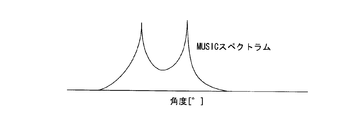
- the accuracy of direction-of-arrival estimation changes due to the variable step ⁇ of ⁇ in the arrival angle evaluation function. That is, when the variable step ⁇ is increased, the amount of calculation over the entire range in which ⁇ is varied decreases, but the peak direction of the arrival direction evaluation function cannot be accurately detected, and the accuracy deteriorates. On the other hand, by reducing the variable step ⁇ , it is possible to accurately detect the peak direction of the arrival direction evaluation function, but the MUSIC method has a disadvantage that the amount of calculation over the entire range in which ⁇ is varied increases. ing.
- the present invention has been made in view of such circumstances, and when performing arrival wave direction detection using eigenexpansion such as the MUSIC method or the minimum norm method, the variable step is reduced and the amount of calculation for angle detection is reduced.
- An object of the present invention is to provide an electronic scanning millimeter-wave radar device and a reception wave direction estimation program that can be reduced.
- an electronic scanning radar device mounted on a moving body: a transmission unit that transmits a transmission wave; and a reflected wave from a target of the transmission wave is received A reception unit composed of a plurality of antennas; a beat signal generation unit that generates a beat signal from the transmission wave and the reflected wave; and complex data obtained by frequency-decomposing the beat signal into a predetermined number of beat frequencies A frequency resolving processing unit that calculates a peak value from the intensity value of the beat frequency to detect the presence of the target; complex data of a detected beat frequency at which the target is detected for each antenna A correlation matrix calculation unit for calculating a correlation matrix from each of the targets; the target in the current detection cycle and the past detection cycle; A target concatenation processing unit that correlates with separation and relative velocity; a correlation matrix that generates an average correlation matrix that weights and averages the correlation matrix of the target of the current detection cycle and the correlation matrix of the target of the associated past detection cycle An electronic scanning radar apparatus comprising a transmission unit that transmits a transmission wave; and
- the electronic scanning radar apparatus may be configured as follows: When the target connection processing unit associates the targets in the current and past detection cycles, the detection beat of the current detection cycle Depending on whether the distance and relative speed obtained by the frequency are included in the distance range and the relative speed range that are predicted and set in advance by the distance and relative speed obtained by the past detection cycle, respectively, between the targets. Detects whether there is an association.
- the electronic scanning radar apparatus may be configured as follows: distance, relative velocity, and correlation matrix respectively corresponding to one or more past cycles of the associated target are stored.
- a storage unit that performs weighted averaging of a correlation matrix between a target in a current detection cycle and a target in a plurality of time-series past detection cycles associated with the current target.
- An average correlation matrix is generated, and the current target distance, relative velocity, and correlation matrix are associated with the associated past target distance, relative velocity, and correlation matrix, and stored in the storage unit.
- the electronic scanning radar apparatus described above may be configured as follows: Complex number data of a detected beat frequency corresponding to the associated target is stored corresponding to one or a plurality of cycles.
- a storage unit when a past detection cycle target associated with a current detection cycle target is detected, the correlation matrix calculation unit calculates the correlation matrix from complex number data of the past detection cycle.
- the target concatenation processor generates a weighted average correlation matrix between a target in a current detection cycle and a past target associated with the current target, and the associated current target Complex data of distance, relative speed and detected beat frequency is stored in the associated past detection cycle. Distance of the target in Le, in association with the relative velocity and complex data stored.
- the electronic scanning radar apparatus described above may be configured as follows: digital that performs digital beamforming in the channel direction and detects the presence and orientation of the target based on the complex data for each antenna. A beam forming unit; detecting the azimuth of the target by the digital beam forming from the beat frequency in the current detection cycle, and associating the target in the detection cycle with the present and the past by the distance, relative velocity, and azimuth. .
- the electronic scanning radar apparatus described above may be configured as follows: digital that performs digital beamforming in the channel direction and detects the presence and orientation of the target based on the complex data for each antenna. It further has a beam forming unit, detects the direction of the target by the digital beam forming from the beat frequency in the current detection cycle, and associates the target in the detection cycle with the current and the past based on the distance, relative speed, and direction. .
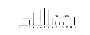
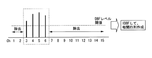
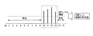
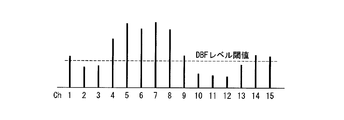
- the electronic scanning radar apparatus described above may be configured as follows: the digital beam forming unit indicates the intensity of the spectrum for each angle channel by performing digital beam forming using the complex number data.
- the digital beamforming detection target exists in this angle channel
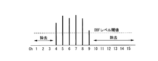
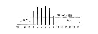
- a channel deleting unit that detects and replaces the spectrum intensity of the angle channel in which the presence of the digital beamforming detection target is not detected with “0” and outputs the new spatial complex data; and reverses the new spatial complex data
- the correlation matrix calculation section calculates a correlation matrix from the restored complex number data.
- the electronic scanning radar apparatus described above may be configured as follows: the digital beam forming unit indicates the intensity of the spectrum for each angle channel by performing digital beam forming using the complex number data.
- the digital beamforming detection target exists in this angle channel
- a channel deleting unit that detects and replaces the spectrum intensity of the angle channel in which the presence of the digital beamforming detection target is not detected with “0” and outputs the new spatial complex data; and reverses the new spatial complex data
- digital beamforming, and the inverse digital beam forming unit for generating a restored complex number data; further wherein the correlation matrix calculation section calculates a correlation matrix from the restored complex number data.
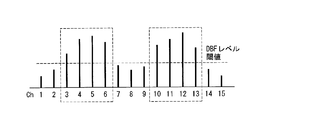
- the electronic scanning radar apparatus may be configured as follows: when the channel deletion unit detects a plurality of digital beamforming detection targets, an angle corresponding to each of the digital beamforming detection targets By dividing the spectrum for each channel range, spatial complex number data is generated for each digital beamforming detection target, and the inverse digital beamforming unit performs inverse digital beamforming for the spatial complex number data for each digital beamforming detection target. Thus, the reproduction complex number data for each digital beam forming detection target is generated, and the correlation matrix calculation unit calculates the digital beam from the reproduction complex number data for each digital beam forming detection target. Calculating a correlation matrix for each Omingu detection target.
- the electronic scanning radar apparatus may be configured as follows: when the channel deletion unit detects a plurality of digital beamforming detection targets, an angle corresponding to each digital beamforming detection target Spatial complex number data for each digital beamforming detection target is generated by dividing the spectrum for each channel range; and the inverse digital beamforming unit performs inverse digital beamforming for the spatial complex number data for each digital beamforming detection target.
- the reproduction complex number data for each digital beam forming detection target is generated; and the correlation matrix calculating unit calculates the digital complex number from the reproduction complex number data for each digital beam forming detection target. Calculating a correlation matrix for each forming detection target.
- the electronic scanning radar apparatus described above may be configured as follows: the correlation matrix filter unit corresponds to the relative speed, and a weighting coefficient for weighted averaging is changed for each target.
- the electronic scanning radar apparatus described above may be configured as follows: The lateral positional change amount of the target obtained from the past and present azimuth and distance exceeds a preset range.
- the correlation matrix filter unit changes the weighting coefficient for weighted averaging for each target.
- the electronic scanning radar apparatus may be configured as follows: The number of past cycles used when the target connection processing unit averages is changed in accordance with the relative speed.
- the following method is provided: a method of estimating a received wave direction by an electronic scanning radar device mounted on a moving body: a transmission process of transmitting a transmission wave from a transmission unit; A reception process in which a reception unit including a plurality of antennas receives a reflected wave by the target of the transmission wave; a beat signal generation process in which a beat signal generation unit generates a beat signal from the transmission wave and the reflection wave; and frequency decomposition A frequency resolving process in which the processing unit frequency-decomposes the beat signal into beat frequencies of a predetermined number of decompositions to calculate complex number data; a target detection unit detects a peak value from the intensity value of the beat frequency and A target detection process for detecting presence; and a complex of a detected beat frequency at which the correlation matrix calculation unit detects the target for each antenna.
- a correlation matrix calculation process for calculating a correlation matrix from each data a target connection processing unit in which a target connection processing unit associates a target in a current detection cycle and a past detection cycle with a distance and a relative speed; a correlation matrix filter unit
- the following program is provided: a program for causing a computer to control the operation of estimating a received wave direction by an electronic scanning radar apparatus mounted on a moving body: a transmission unit transmits A transmission process for transmitting a wave; a reception process for receiving a reflected wave from the target of the transmission wave by a plurality of antennas; and a beat for generating a beat signal from the transmission wave and the reflected wave by a beat signal generating part A signal generation process; a frequency resolution processing process in which the frequency resolution processing unit frequency-decomposes the beat signal into beat frequencies of a preset resolution number to calculate complex number data; a target detection unit peaks from the intensity value of the beat frequency Target detection processing for detecting a value to detect the presence of a target; and a correlation matrix calculation unit for each antenna A correlation matrix calculation process for calculating a correlation matrix from each complex number data of the detected beat frequency at which the target is detected; target connection in which the target connection processing unit associates the target in the current detection cycle
- an electronic scanning radar apparatus mounted on a moving body: a transmission unit that transmits a transmission wave; a reflected wave from a target of the transmission wave; A receiving unit configured by a plurality of antennas that receive a certain incoming wave; a beat signal generating unit that generates a beat signal having a frequency difference between the transmitted wave and the reflected wave; and presetting the beat signal in time series
- a frequency decomposition processing unit that calculates complex number data by frequency decomposition into beat frequencies of the number of decompositions; a peak detection unit that detects a peak value from the intensity value of each beat frequency and detects the presence of a target;
- a correlation matrix calculation unit for calculating a correlation matrix from each complex number data of the detected beat frequency at which the target is detected; an eigenvalue for calculating an eigenvalue from the correlation matrix
- An output unit a comparison unit that compares the normalized eigenvalue and a preset threshold value; among eigenvalues corresponding to the
- the electronic scanning radar apparatus may be configured as follows: the eigenvalue calculation unit divides and normalizes all eigenvalues by the eigenvalue having the maximum value among the calculated eigenvalues.
- the comparison unit compares the normalized eigenvalue with the preset threshold value.
- the electronic scanning radar apparatus described above may be configured as follows: the eigenvalue calculation unit divides all elements of the correlation matrix by elements of the maximum value in the correlation matrix, and The eigenvalue is calculated by using the normalized correlation matrix, and the comparison unit compares the eigenvalue with the preset threshold value.
- the electronic scanning radar apparatus described above may be configured as follows: the determination unit compares a maximum eigenvalue threshold set in advance with a maximum eigenvalue in the obtained eigenvalue, and the maximum When the eigenvalue exceeds the maximum eigenvalue threshold, the eigenvalue is recognized as an effective reception level, and the number of incoming waves is estimated.
- the electronic scanning radar apparatus described above may be configured as follows: the eigenvalue calculation unit converts all elements of the correlation matrix by elements having maximum values in diagonal elements of the correlation matrix. The eigenvalue is calculated by the correlation matrix with the elements normalized, and the comparison unit compares the eigenvalue with the preset threshold value.
- the electronic scanning radar apparatus may be configured as follows: a peak value comparison unit that compares the peak value with a preset effective reception level; When the effective reception level is exceeded, the determination unit estimates the number of incoming waves assuming that the eigenvalue is the effective determination level.
- the electronic scanning radar apparatus described above may be configured as follows: a maximum correlation matrix diagonal element threshold that is determined in advance by the determination unit, and a diagonal element in the obtained correlation matrix; When the maximum value of the diagonal element exceeds the maximum correlation matrix diagonal element threshold value, the arrival wave is estimated as the eigenvalue is an effective reception level.
- the electronic scanning radar apparatus may be configured as follows: the peak detection unit performs digital beam forming in the channel direction based on the complex number data for each antenna, and detects the presence of the target. It has a digital beam forming unit for detection.
- the above electronic scanning radar apparatus may be configured as follows: a space indicating the intensity of the spectrum for each angle channel by the digital beam forming unit performing digital beam forming using the complex number data. Calculates complex data and detects the presence of the target when the intensity of the spectrum of the adjacent angle channel exceeds the preset digital beamforming threshold within the range of the preset number of angle channels.
- a channel deletion unit that replaces the spectrum intensity of the angle channel that has not been replaced with “0” and outputs new spatial complex data; and an inverse that generates reproduced complex data by performing inverse digital beamforming on the new spatial complex data Digital beam formi A grayed portion; further wherein the correlation matrix calculation section calculates a correlation matrix from the restored complex number data.
- the above-described electronic scanning radar apparatus may be configured as follows: the peak detector converts the sum of complex data of all antennas into a frequency spectrum and detects a target based on the peak value of the spectrum. To do.
- the following method is provided: a method of estimating a received wave direction by an electronic scanning radar device mounted on a moving body: a transmission process in which a transmission unit transmits a transmission wave; and reception A reception process in which a unit receives an incoming wave that is a reflected wave from a target of the transmission wave by a plurality of antennas; and a beat signal generation unit generates a beat signal having a frequency that is a difference between the transmission wave and the reflected wave A beat signal generating process to be generated; a frequency resolving process in which the frequency resolving unit frequency-decomposes the beat signal into beat frequencies of a predetermined number of decompositions in time series to calculate complex data; A peak detection process in which a peak value is detected from the intensity value of the frequency to detect the presence of the target; and a correlation matrix calculation unit detects the target for each antenna A correlation matrix calculation process for calculating a correlation matrix from each of the complex number data of the detected beat frequency; an
- the following program is provided: a program for causing a computer to control an operation of estimating a received wave direction of an electronic scanning radar apparatus mounted on a moving body: a transmission unit transmits A transmission process for transmitting a wave; a reception process in which a reception unit receives an incoming wave that is a reflected wave from the target of the transmission wave by a plurality of antennas; and a beat signal generation unit for the transmission wave and the reflected wave A beat signal generation process for generating a beat signal having a frequency difference between the frequency and a frequency decomposition process in which the frequency decomposition processing unit frequency-decomposes the beat signal into beat frequencies of a predetermined number of decompositions to calculate complex data Processing; peak detection processing in which the peak detector detects the peak value from the intensity value of each beat frequency and detects the presence of the target; correlation matrix calculation A correlation matrix calculation process that calculates a correlation matrix from each complex number data of a detected beat frequency at which the target is detected for each antenna; an
- an electronic scanning radar device mounted on a moving body: a transmission unit that transmits a transmission wave; a reflected wave from a target of the transmission wave; A receiving unit configured by a plurality of antennas that receive a certain incoming wave; a beat signal generating unit that generates a beat signal having a frequency difference between the transmitted wave and the reflected wave; and presetting the beat signal in time series
- a frequency resolution processing unit that calculates complex number data by frequency decomposition into beat frequencies of the decomposed number
- an angle range setting unit that calculates an angle range in which a target exists from the complex number data; and calculates an angle spectrum within the angle range
- An electronic scanning radar apparatus comprising:
- the electronic scanning radar apparatus may be configured as follows: the angle range setting unit performs digital beam forming on the complex number data in an antenna arrangement direction, and the spectrum of each angle channel is calculated.
- a digital beam forming processing unit that calculates intensity, detects the presence of a target, and obtains azimuth information; and range detection that sets an angular range for calculating an angular spectrum based on frequency axis data and azimuth information on the target And a section.
- the electronic scanning radar apparatus described above may be configured as follows: the angle range setting unit in the angle channel direction based on the spectrum intensity for each angle channel calculated by the digital beamforming processing unit.
- a channel deletion unit that divides the signal into a plurality of groups according to the presence or absence of the target and sets the spectrum intensity of the angle channel where the target does not exist to “0”; and inverse digital beamforming the spectrum intensity for each angle channel;
- An inverse digital beamforming processing unit that returns the complex number data for each antenna and outputs the reproduced complex number data, and the range detecting unit includes the reproduced complex number data, direction information in which the target exists, and a received wave number estimation value.
- the angle range for calculating the angle spectrum based on A constant.
- the electronic scanning radar apparatus described above may be configured as follows: the angle range setting unit is arranged in the angle channel direction according to the spectrum intensity for each angle channel calculated by the digital beamforming processing unit.
- a channel deletion unit that divides the signal into a plurality of groups according to the presence or absence of the target and sets the spectrum intensity of the angle channel where the target does not exist to “0”; and inverse digital beamforming the spectrum intensity for each angle channel;
- An inverse digital beamforming processing unit that returns the complex number data for each antenna and outputs the reproduced complex number data, and the azimuth detecting unit converts the angle based on the reproduced complex number data and the received wave number estimation value. Calculate the corresponding solution.
- the electronic scanning radar apparatus may be configured as follows: the angle range setting unit is arranged in the angle channel direction according to the spectrum intensity for each angle channel calculated by the digital beamforming processing unit.
- a channel deletion unit that divides the signal into a plurality of groups according to the presence or absence of the target and sets the spectrum intensity of the angle channel where the target does not exist to “0”; and inverse digital beamforming the spectrum intensity for each angle channel;
- An inverse digital beamforming processing unit that returns the complex number data for each antenna and outputs it as reproduced complex number data; and a storage unit that stores azimuth information of each target in a past azimuth detection cycle, and the range detection unit , The reproduction complex number data, and stored in the storage unit Past and azimuth information of the bearing detection cycle that sets the angle range for calculating the angular spectrum based on the reception wave number estimating value.
- the electronic scanning radar apparatus described above may be configured as follows: the received wave number estimation value is a fixed value.
- the angle range setting unit includes a peak detection unit that detects the presence of a target from the peak value of the intensity of the frequency axis;
- a storage unit that stores azimuth information of each target in the azimuth detection cycle; and the azimuth information of the past azimuth detection cycle stored in the storage unit is used to limit the angle range and store the obtained angle range.
- the following method is provided: a method of estimating a received wave direction by an electronic scanning radar device mounted on a moving body: a transmission process in which a transmission unit transmits a transmission wave; and reception A reception process in which a unit includes a plurality of antennas that receive an incoming wave that is a reflected wave from the target of the transmission wave; and a beat signal generation unit that generates a beat signal having a frequency that is a difference between the transmission wave and the reflected wave A beat signal generation process to be generated; a frequency resolution processing process in which a frequency resolution processing unit frequency-decomposes the beat signal into beat frequencies of a preset number of resolutions to calculate complex data; and an angle range setting unit An angle range setting process for calculating an angle range where the target exists from complex data; and an azimuth detection in which the azimuth detection unit calculates an angle spectrum within the angular range.
- receiving wave direction estimating method characterized by having a.
- the following program is provided: a program for causing a computer to control an operation of estimating a direction of a received wave by an electronic scanning radar apparatus mounted on a moving body: a transmission unit transmits a transmission wave A transmission process for transmission; a reception process for receiving an incoming wave that is a reflected wave from the target of the transmission wave by a plurality of antennas; and a beat signal generator for calculating a frequency of a difference between the transmission wave and the reflected wave A beat signal generating process for generating a beat signal having; a frequency resolving process in which a frequency resolving unit frequency-decomposes the beat signal into beat frequencies of a predetermined number of decompositions in time series to calculate complex number data; and angle range setting An angle range setting process in which a unit calculates an angle range in which a target exists from the complex number data; and an azimuth detection unit within the angle range Receiving wave direction estimation program characterized by having; and azimuth detection process of calculating
- the target concatenation processing unit performs the correlation matrix averaging process after associating the same target in the present and the past.
- eigenvalue calculation and spectrum calculation for example, MUSIC
- the azimuth detection processing performed in the subsequent stage can be executed with high accuracy, and the final calculation is performed as compared with the case where the calculation is performed using the correlation matrix of only the current time. Recognition performance in the distance and direction of the target can be improved.
- a plurality of correlation matrices or complex number data is stored in the target unit, and averaging processing is performed using all of these, so regardless of variations in the distance to the target.
- the recognition performance in the final target distance and orientation can be improved.
- the target matrix unit is arbitrarily changed in number of detection cycles of the correlation matrix used for averaging the correlation matrix based on the relative speed with the target.
- the number of detection cycles is reduced when the distance of the sensor is changing, and the number of detection cycles is increased when the distance to the target is stable. Therefore, the correlation matrix filter unit can have a unique filter characteristic, and the recognition performance in the final target distance and direction can be improved.
- the weighting factor to be averaged used for averaging of the correlation matrix is changed in units of targets based on the relative speed with the target.
- the correlation matrix filter unit can have an appropriate filter characteristic according to the state of the relative velocity, and the recognition performance in the final target distance and direction can be improved.
- the weighting coefficient for weighted averaging is calculated.
- the correlation matrix filter unit can have an appropriate filter characteristic. The recognition performance in the final target distance and direction can be improved.
- the storage capacity can be reduced as compared with a case where data is simply stored as a correlation matrix.
- the DBF unit that detects the azimuth by the DBF from the frequency-resolved beat frequency is included, not only the prediction range from the distance and the relative speed but also the azimuth range is included. Therefore, the accuracy of associating current and past correlation matrices can be improved.
- the spectrum is divided for each angular channel range corresponding to the DBF detection target and each spatial complex number data is generated, and the IDBF unit generates the spatial complex number for each DBF detection target. Since the correlation matrix for each DBF detection target is calculated from the reproduction complex number data obtained by inverse DBF of the data, the correlation matrix used when performing eigenvalue calculation includes only the received wave component for each DBF detection target. Even if reception waves arrive from more than that number of receiving antennas and sub-arrays, it is possible to improve the direction and distance recognition performance with high accuracy without erroneous eigenvalue calculation for each DBF detection target. .
- the number of eigenvalues exceeding a preset threshold value is output as the number of incoming waves.
- the number of eigenvalues exceeding the threshold can be estimated as the number of incoming waves, it is not necessary to set a threshold for comparison with the eigenvalue for each beat frequency as in the prior art, the storage capacity can be reduced, and Since only a simple calculation for comparing the eigenvalue and the threshold is performed, it is possible to reduce the processing time for calculating the number of incoming waves.
- the determination is performed by comparing the normalized eigenvalue and the threshold value, the fluctuation of the entire eigenvalue due to the target RCS, clutter, noise, or the like is detected. Robustness can be given.
- the spectrum peak value (the added value of the spectrum for each receiving antenna or the peak value in the DBF) at the frequency point (beat frequency value) on the frequency axis after frequency conversion is used as the target. Since the processing after the correlation matrix is not executed for beat frequency values with a low peak value, even if the eigenvalue exceeds the above threshold, the incoming wave from the target by multipath from the road surface, etc. When the frequency becomes weak, it is possible to prevent an erroneous estimation of the number of incoming waves.
- the spectrum corresponding to the angle channel is set to “0”, and IDBF (When inverse DBF) is performed and the correlation matrix is calculated with the reproduction complex data in the direction of the receiving antenna, the eigenvalue is only the range divided for each target in the DBF, which is equivalent to receiving only the divided incoming waves. Thus, even when the number of incoming waves is larger than the number of receiving antennas, erroneous estimation is not performed in the eigenvalue calculation.
- the determination unit since the determination unit performs the process of estimating the number of incoming waves only when the value of the maximum eigenvalue in the obtained eigenvalue exceeds a preset maximum eigenvalue threshold, In the case of an embodiment in which eigenvalues are obtained from the correlation matrix of all frequency points or a specific frequency point range without using the result of detecting the target from the peak value of the spectrum at the later frequency point, multipath from the road surface, etc. Therefore, when the incoming wave from the target becomes weak, no erroneous estimation is performed.
- normalization is performed by dividing all elements by the maximum value of elements in the correlation matrix, and eigenvalues are calculated by calculating eigenvalues using the normalized correlation matrix.
- the accuracy of floating-point arithmetic at the time is improved, the number of computations until the convergence of eigenvalue and eigenvector computation algorithms (Jacobi method, QR method, etc.) can be reduced, and the computation of eigenvalues and eigenvectors can be speeded up.
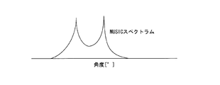
- the orientation detection unit since the target orientation at the past cycle can be confirmed by referring to the target orientation in the past cycle stored in the storage unit, the orientation detection unit For example, when calculating the angle spectrum, the angle spectrum can be calculated preferentially in a specific angle range that matches the direction of the past cycle, and the variable step ⁇ can be reduced to make the calculation resolution finer. Thus, the calculation accuracy of the direction of the arrival direction of the incoming wave can be improved.
- DBF of the beat frequency where the target exists is performed, unnecessary angle channels are deleted (spectrum intensity is set to “0”), IDBF is performed after deletion, and reproduction is performed. Since the correlation matrix is generated in the direction of the receiving channel from the complex number data and the eigenvalue calculation is performed, it is equivalent to receiving only the divided incoming waves, and it is assumed that more incoming waves are received than the number of receiving antennas. However, the direction in which the incoming wave arrives can be calculated without error in the eigenvalue calculation.
- the maximum number of incoming waves (number of targets) in practical use is determined if the divided narrow angle range is used. Since it is possible to assume a value, spectrum estimation can be performed with a fixed number of incoming waves.
- a plurality of angle ranges are set corresponding to a plurality of incoming waves, In the angle range, it is possible to separate the incoming waves and estimate the direction with high accuracy.
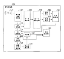
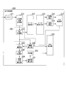
- FIG. 1 is a block diagram showing a configuration example of an electronic scanning radar apparatus according to the first embodiment of the present invention.
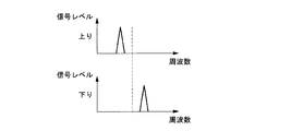
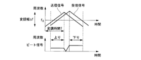
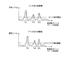
- FIG. 2A is a conceptual diagram illustrating the generation of beat signals in the rising and falling regions of the triangular wave by the transmission wave and the reception wave.
- FIG. 2B is a conceptual diagram illustrating the generation of beat signals in the rising and falling regions of the triangular wave by the transmission wave and the reception wave.
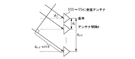
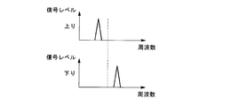
- FIG. 3 is a conceptual diagram illustrating the received wave at the receiving antenna.
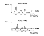
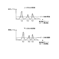
- FIG. 4 is a graph showing the result of the frequency decomposition of the beat signal and showing the beat frequency (horizontal axis) and its peak value (vertical axis).
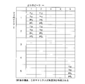
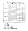
- FIG. 5 is a table showing a matrix of beat frequencies in the ascending region and the descending region in the combination unit 24, and a distance and a relative speed at an intersection of the matrices, that is, a combination of beat frequencies in the ascending region and the descending region.
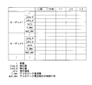
- FIG. 6 is a table showing the distance and relative speed for each target in the current detection cycle.
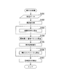
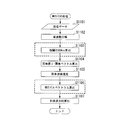
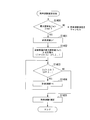
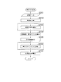
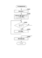
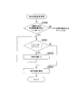
- FIG. 7 is a flowchart for explaining the processing of MUSIC.
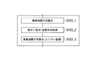
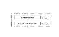
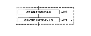
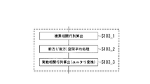
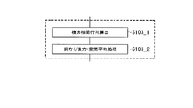
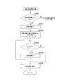
- FIG. 8A is a flowchart showing substeps performed in step S103 of the flowchart of FIG.
- FIG. 8B is a flowchart showing substeps performed in step S103 of the flowchart of FIG.
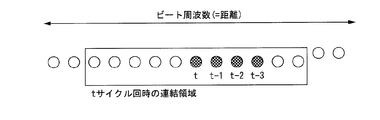
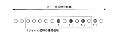
- FIG. 9 is a conceptual diagram illustrating a process when calculating a spatial average of a correlation matrix.
- FIG. 10 is a conceptual diagram illustrating a table configuration in which a correlation matrix is described in association with the distance and relative speed of the past detection cycle, which is used when the current detection cycle and the past detection cycle are associated with each other.
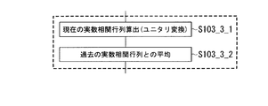
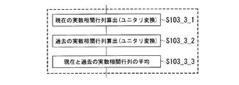
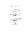
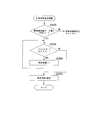
- FIG. 11 is a flowchart showing a sub-step of step S103_3 in FIG. 8A.
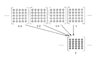
- FIG. 12 is a conceptual diagram illustrating the averaging process of the current detection cycle and the past detection cycles (plural).
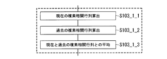
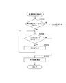
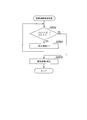
- FIG. 13 is a flowchart showing substeps of step S103_1 in FIG. 8B.
- FIG. 14A is a conceptual diagram illustrating the number of detection cycles associated with detection cycles.
- FIG. 14B is a conceptual diagram illustrating the number of detection cycles associated with detection cycles.
- FIG. 14A is a conceptual diagram illustrating the number of detection cycles associated with detection cycles.
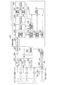
- FIG. 15 is a block diagram showing a configuration example of an electronic scanning radar apparatus according to a modification of the first embodiment of the present invention.
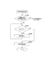
- FIG. 16 is a flowchart showing substeps of step S103_3 in FIG. 8A.
- FIG. 17 is a flowchart showing substeps of step S103_1 in FIG. 8B.
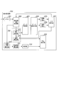
- FIG. 18 is a block diagram showing a configuration example of an electronic scanning radar apparatus according to the second embodiment of the present invention.
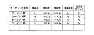
- FIG. 19 shows a table configuration in which a correlation matrix is described in association with the distance, the vertical position, the horizontal position, and the relative speed of the past detection cycle, which is used when the current detection cycle and the past detection cycle are associated with each other.
- FIG. 20 is a table showing the correspondence between each angle and frequency point for each target in the current detection cycle.
- FIG. 21 is a block diagram showing a configuration example of an electronic scanning radar apparatus according to the third embodiment of the present invention.
- FIG. 22 is a table showing the distance, vertical position, horizontal position, and relative speed for each target in the current detection cycle.
- FIG. 23 is a block diagram showing a configuration example of an electronic scanning radar apparatus according to the fourth embodiment of the present invention.
- FIG. 24A is a conceptual diagram illustrating processing of spectrum intensity in each angle channel.
- FIG. 24B is a conceptual diagram illustrating processing of spectrum intensity in each angle channel.
- FIG. 24C is a conceptual diagram illustrating processing of spectrum intensity in each angle channel.
- FIG. 25A is a conceptual diagram illustrating processing of spectrum intensity in each angle channel.
- FIG. 25B is a conceptual diagram illustrating processing of spectrum intensity in each angle channel.
- FIG. 25C is a conceptual diagram illustrating processing of spectrum intensity in each angle channel.
- FIG. 26 is a block diagram showing a configuration example of an electronic scanning radar apparatus according to the fifth embodiment of the present invention.
- FIG. 27A is a conceptual diagram illustrating the generation of beat signals in the rising region and falling region of the triangular wave by the transmission wave and the reception wave.
- FIG. 27B is a conceptual diagram illustrating generation of beat signals in the rising and falling regions of the triangular wave by the transmission wave and the reception wave.
- FIG. 28 is a conceptual diagram illustrating a received wave at the receiving antenna.
- FIG. 29 is a graph showing the result of frequency decomposition of the beat signal and showing the beat frequency (horizontal axis) and its peak value (vertical axis).
- FIG. 30 is a flowchart for explaining the MUSIC process.
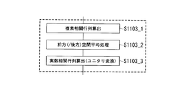
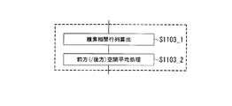
- FIG. 31A is a flowchart showing substeps performed in step S1103 of the flowchart of FIG.
- FIG. 31B is a flowchart showing the sub-steps performed in step S1103 of the flowchart of FIG.
- FIG. 32 is a conceptual diagram illustrating processing when calculating a spatial average of a correlation matrix.
- FIG. 33 is a flowchart for explaining in detail the process for estimating the number of incoming waves performed in step S1105 of FIG.
- FIG. 33 is a flowchart for explaining in detail the process for estimating the number of incoming waves performed in step S1105 of FIG.
- FIG. 34 is a flowchart for explaining in detail another process for estimating the number of incoming waves performed in step S1105 of FIG.
- FIG. 35 is a flowchart for explaining in detail another process for estimating the number of incoming waves performed in step S1105 of FIG.
- FIG. 36 is a flowchart for explaining in detail another process for estimating the number of incoming waves performed in step S1105 of FIG.
- FIG. 37 is a flowchart for explaining in detail another process for estimating the number of incoming waves performed in step S1105 of FIG.
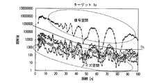
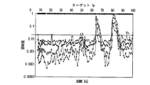
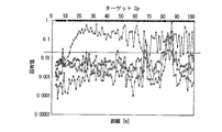
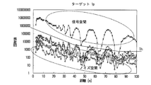
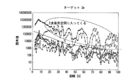
- FIG. 38A is a graph showing the correspondence between the distance when the incoming wave is 1 and the eigenvalue at each distance.
- FIG. 38B is a graph showing the correspondence between the distance when the incoming wave is 1 and the eigenvalue at each distance.
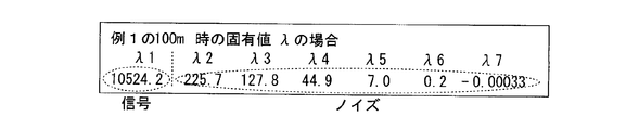
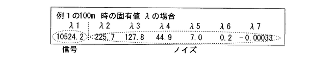
- FIG. 38C is a table showing eigenvalues ⁇ x at a distance of 100 (m) when the number of incoming waves is 1, and showing a difference in numerical values between eigenvalues ⁇ 1 in the signal space and eigenvalues in other noise spaces.
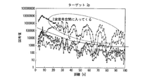
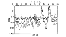
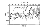
- FIG. 39A is a graph showing the correspondence between the distance when the incoming wave is 2 and the eigenvalue at each distance.
- FIG. 39B is a graph showing the correspondence between the distance when the incoming wave is 2 and the eigenvalue at each distance.
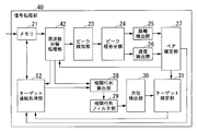
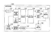
- FIG. 40 is a block diagram illustrating a configuration example of the signal processing unit 120 in the electronic scanning radar apparatus according to the sixth embodiment of the present invention.
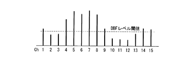
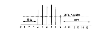
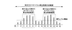
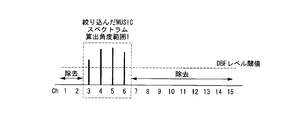
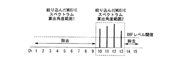
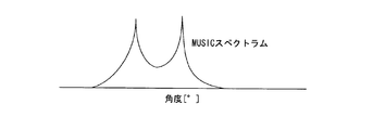
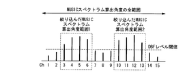
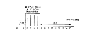
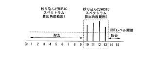
- FIG. 41A is a graph for explaining the narrowing-down process of the angle range for calculating the MUSIC spectrum using the DBF process.
- FIG. 41B is a graph for explaining the narrowing-down process of the angle range for calculating the MUSIC spectrum using the DBF process.
- FIG. 41C is a graph for explaining the narrowing-down process of the angle range for calculating the MUSIC spectrum using the DBF process.
- FIG. 42A is a graph for explaining the narrowing-down process of the angle range for calculating the MUSIC spectrum using the DBF process.
- FIG. 42B is a graph for explaining the narrowing-down process of the angle range for calculating the MUSIC spectrum using the DBF process.
- FIG. 42C is a graph for explaining the narrowing-down process of the angle range for calculating the MUSIC spectrum using the DBF process.
- FIG. 43 is a block diagram showing a configuration example of the signal processing unit 120 in the electronic scanning radar apparatus according to the seventh embodiment of the present invention.
- FIG. 44 is a block diagram illustrating a configuration example of an electronic scanning radar apparatus according to an embodiment of the present invention.
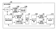
- FIG. 45 is a block diagram showing a configuration example of the signal processing unit 20 in the electronic scanning radar apparatus according to the eighth embodiment of the present invention.
- FIG. 46A is a conceptual diagram illustrating the generation of beat signals in the rising and falling regions of the triangular wave by the transmission wave and the reception wave.
- FIG. 46A is a conceptual diagram illustrating the generation of beat signals in the rising and falling regions of the triangular wave by the transmission wave and the reception wave.
- FIG. 46B is a conceptual diagram illustrating generation of beat signals in the rising and falling regions of the triangular wave by the transmission wave and the reception wave.
- FIG. 47 is a conceptual diagram illustrating the received wave at the receiving antenna.
- FIG. 48 is a graph showing the result of the frequency decomposition of the beat signal and showing the beat frequency (horizontal axis) and its peak value (vertical axis).
- FIG. 49A is a graph for explaining the narrowing-down process of the angle range for calculating the MUSIC spectrum using the DBF process.
- FIG. 49B is a graph for explaining the narrowing-down process of the angle range for calculating the MUSIC spectrum using the DBF process.
- FIG. 49A is a graph for explaining the narrowing-down process of the angle range for calculating the MUSIC spectrum using the DBF process.
- FIG. 49B is a graph for explaining the narrowing-down process of the angle range for calculating the MUSIC spectrum using the DBF process.
- FIG. 49C is a graph for explaining the narrowing-down process of the angle range for calculating the MUSIC spectrum using the DBF process.
- FIG. 50A is a graph for explaining the narrowing-down process of the angle range for calculating the MUSIC spectrum using the DBF process.
- FIG. 50B is a graph for explaining the narrowing-down process of the angle range for calculating the MUSIC spectrum using the DBF process.
- FIG. 50C is a graph for explaining the narrowing-down process of the angle range for calculating the MUSIC spectrum using the DBF process.
- FIG. 51 is a flowchart for explaining the MUSIC process.
- FIG. 52A is a flowchart showing substeps performed in step S2103 of the flowchart of FIG. FIG.
- FIG. 52B is a flowchart showing substeps performed in step S2103 of the flowchart of FIG.
- FIG. 53 is a conceptual diagram illustrating processing when calculating a spatial average of a correlation matrix.
- FIG. 54 is a flowchart for explaining in detail the process of estimating the number of incoming waves performed in step S2105 of FIG.
- FIG. 55 is a flowchart for explaining in detail another process of estimating the number of incoming waves performed in step S2105 of FIG.
- FIG. 56 is a flowchart for explaining in detail another process for estimating the number of incoming waves performed in step S2105 of FIG.
- FIG. 57 is a flowchart illustrating in detail the other estimation process of the number of incoming waves performed in step S2105 of FIG.
- FIG. 59A is a graph showing the correspondence between the distance when the incoming wave is 1 and the eigenvalue at each distance.
- FIG. 59B is a graph showing the correspondence between the distance when the incoming wave is 1 and the eigenvalue at each distance.
- FIG. 59C is a table showing the eigenvalue ⁇ x at a distance of 100 (m) when the number of incoming waves is 1, and showing the numerical difference between the eigenvalue ⁇ 1 in the signal space and the eigenvalue in the other noise space.
- FIG. 59A is a graph showing the correspondence between the distance when the incoming wave is 1 and the eigenvalue at each distance.
- FIG. 59B is a graph showing the correspondence between the distance when the incoming wave is 1 and the eigenvalue at each distance.
- FIG. 59C is a table showing the eigenvalue ⁇ x at a distance of 100 (m) when the number of incoming waves is 1, and showing the numerical difference between the eigenvalue ⁇ 1
- FIG. 60A is a graph showing the correspondence between the distance when the incoming wave is 2 and the eigenvalue at each distance.
- FIG. 60B is a graph showing the correspondence between the distance when the incoming wave is 2 and the eigenvalue at each distance.
- FIG. 61 is a block diagram showing a configuration example of the signal processing unit 220 in the electronic scanning radar apparatus according to the ninth embodiment of the present invention.
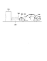
- FIG. 62 shows an electronic scanning radar device and a computer mounted on a moving body. The electronic scanning radar device transmits a transmission wave, and the reflected wave reflected by the transmission wave is reflected on the electronic scanning type. It is the schematic which shows a mode that a radar apparatus receives.
- 11 to 1n receiving antenna, 61 to 6n: mixer (beat signal generating unit), 3 ... transmitting antenna, 4 ... distributor, 51-5n ... filter, 6 ... SW, 7 ... ADC, 8 ... control unit, 9 ... Triangular wave generation unit, 10 ... VCO, 20 ... signal processing unit, 21 ... memory (storage unit), 22 ... frequency decomposition processing unit, 23 ... peak detection unit, 24 ... peak combination unit, 25 ... distance detection unit, 26 ... speed Detection unit, 27, 27B ... Pair determination unit, 28 ... Correlation matrix calculation unit, 29 ... Correlation matrix filter unit, 30 ... Direction detection unit, 31, 31B ... Target determination unit, 32, 32B ... Target connection processing unit, 40 ...
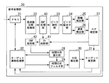
- DBF processing unit 41 ... Ch deletion unit, 42, 43 ... IDBF processing unit, 111 to 11n ... reception antenna, 161 to 16n ... mixer (beat signal generation unit), 103 ... transmission antenna, 104 ... distributor 151 to 15n: filter, 106 ... SW, 107 ... ADC, 108 ... control unit, 109 ... triangular wave generation unit, 110 ... VCO, 120 ... signal processing unit, 121 ... memory (storage unit), 122 ... frequency decomposition processing unit, 123: Peak detection unit, 124: Peak combination unit, 125 ... Distance detection unit, 126 ... Speed detection unit, 127, 127B ... Pair determination unit, 128 ... Correlation matrix calculation unit, 130 ...
- Direction detection unit 131 ... Eigen value calculation unit , 132 ... determination unit, 133 ... DBF processing unit, 134 ... Ch deletion unit, 135 ... IDBF processing unit, 211 to 21n ... reception antenna, 261 to 26n ... mixer (beat signal generation unit), 203 ... transmission antenna, 204 ... Distributor, 251 to 25n ... filter, 206 ... SW, 207 ... ADC, 208 ... control unit, 209 ... triangular wave generation unit, 210 ... VC , 220 ... Signal processing unit, 221 ... Memory (storage unit), 222 ... Frequency resolution processing unit, 223 ... Peak detection unit, 224 ... Peak combination unit, 225 ... Distance detection unit, 226 ...
- Speed detection unit 227, 227B ... Pair determining unit, 228 ... correlation matrix calculating unit, 230 ... direction detecting unit, 231 ... eigen value calculating unit, 232 ... determining unit, 233 ... DBF processing unit, 234 ... Ch deletion unit, 235 ... IDBF processing unit, 236 ... range detection , 250 ... Angular range setting unit, 301 ... Mobile object, 302 ... Electronic scanning radar device, 303 ... Transmission wave, 304 ... Target, 305 ... Reflected wave, 306 ... Computer
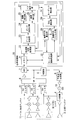
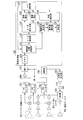
- FIG. 1 is a block diagram showing a configuration example of the first embodiment.
- the electronic scanning radar apparatus according to the first embodiment includes receiving antennas 11 to 1n, mixers (beat signal generating units) 61 to 6n, transmitting antenna 3, distributor 4, filters 51 to 5n, and SW (switch ) 6, ADC (A / D converter) 7, controller 8, triangular wave generator 9, VCO 10, and signal processor 20.
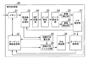
- the signal processing unit 20 includes a memory (storage unit) 21, a frequency separation processing unit 22, a peak detection unit 23, a peak combination unit 24, a distance detection unit 25, a speed detection unit 26, a pair determination unit 27, and a correlation matrix calculation unit 28. , A correlation matrix filter unit 29, an orientation detection unit 30, a target determination unit 31, and a target connection processing unit 32.
- the receiving antennas 11 to 1n receive the reflected wave, that is, the received wave, which is transmitted from the target after the transmitted wave is reflected by the target.
- Each of the mixers 61 to 6n mixes a transmission wave transmitted from the transmission antenna 3 and a signal obtained by amplifying the reception wave received at each of the reception antennas 11 to 1n by an amplifier to cope with each frequency difference. Generated beat signal.
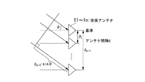
- the transmission antenna 3 transmits a transmission signal obtained by frequency-modulating the triangular wave signal generated by the triangular wave generation unit 9 in a VCO (Voltage Controlled Oscillator) 10 to the target as a transmission wave.
- the distributor 4 distributes the frequency-modulated transmission signal from the VCO 10 to the mixers 61 to 6n and the transmission antenna 3.
- Each of the filters 51 to 5n performs band limitation on the beat signals of Ch1 to Chn corresponding to the reception antennas 11 to 1n generated in the mixers 61 to 6n, respectively, and the band-limited beat signal is SW (switch). 6 is output.
- SW6 sequentially switches beat signals of Ch1 to Chn corresponding to each of the receiving antennas 11 to 1n that have passed through the filters 51 to 5n in response to the sampling signal input from the control unit 8, and performs ADC (A / A D converter) 7.
- the ADC 7 A / D converts the beat signals of Ch1 to Chn corresponding to the receiving antennas 11 to 1n input from the SW6 in synchronization with the sampling signal into digital signals in synchronization with the sampling signal.
- the signal is converted and sequentially stored in the waveform storage area of the memory 21 in the signal processing unit 20.
- the control unit 8 is constituted by a microcomputer or the like, and controls the entire electronic scanning radar apparatus shown in FIG. 1 based on a control program stored in a ROM (not shown) or the like.
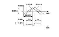
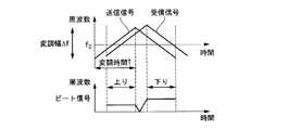
- FIG. 2A and FIG. 2B show a transmission signal obtained by frequency-modulating the signal generated in the triangular wave generation unit 9 of FIG. 1 by the VCO 10 and a state in which the transmission signal is reflected by the target and input as a reception signal.
- the example of FIGS. 2A and 2B shows a case where there is one target. As can be seen from FIG.
- a received signal which is a reflected wave from the target is received with a delay in the right direction (time delay direction) in proportion to the distance from the target with respect to the signal to be transmitted. Further, the reception signal varies in the vertical direction (frequency direction) with respect to the transmission signal in proportion to the relative speed with the target. Then, after the frequency conversion (Fourier transform, DTC, Hadamard transform, wave red transform, etc.) of the beat signal obtained in FIG. 2A, the above signal rises when there is one target as shown in FIG. 2B. Each region and descending region has one peak value.
- the horizontal axis represents frequency and the vertical axis represents intensity.
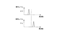
- the frequency decomposition processing unit 22 performs frequency decomposition on each of the rising portion (up) and the falling portion (down) of the triangular wave from the sampled data of the beat signal stored in the memory 21. For example, the frequency decomposition processing unit 22 performs frequency conversion to discrete time by Fourier transform or the like. As a result, as shown in FIG. 2B, a graph of the signal level for each beat frequency subjected to frequency decomposition is obtained in the rising portion and the falling portion.
- the peak detector 23 detects the peak value from the signal level for each beat frequency shown in FIG. 2B, detects the presence of the target, and determines the beat frequency of the peak value (both ascending and descending parts) as the target frequency. Output as.
- the distance detector 25 calculates the distance from the rising portion target frequency fu and the falling portion target frequency fd input from the peak combination portion 24 by the following equation (1).
- the speed detection unit 26 calculates a relative speed by the following equation (2) from the target frequency fu of the rising portion and the target frequency fd of the falling portion input from the peak combination unit 24.
- C speed of light
- ⁇ f frequency modulation width of triangular wave
- f0 Triangular wave center frequency
- T Modulation time (rising part / falling part) fu: target frequency in the rising part
- fd Target frequency in the descending part
- the receiving antennas 11 to 1n in the first embodiment are array-shaped antennas arranged at intervals d as shown in FIG.
- the receiving antennas 11 to 1n are incident waves from the target (incident waves, that is, transmitted waves transmitted from the transmitting antenna 3), which are incident from the direction of the angle ⁇ with respect to the axis perpendicular to the antenna array surface.
- the reflected wave from the target) is input.
- the incoming wave is received at the same angle by the receiving antennas 11 to 1n.
- a phase difference “dn ⁇ 1 ⁇ sin ⁇ ” obtained by the same angle, for example, the angle ⁇ and the distance d between the antennas, is generated between the adjacent receiving antennas.
- digital beam forming DBF for further Fourier transforming the frequency-resolved value for each antenna in the time direction for each antenna, and signal processing such as a super-resolution algorithm The angle ⁇ can be detected.
- the memory 21 stores time series data (ascending portion and descending portion) obtained by A / D converting the received signal in the waveform storage area by the ADC 7 in association with each antenna 11 to 1n. .
- time series data ascending portion and descending portion
- data of 2 ⁇ 256 pieces ⁇ the number of antennas is stored in the waveform storage area.
- the frequency resolution processing unit 22 converts each beat signal corresponding to each Ch1 to Chn (each antenna 11 to 1n) into a frequency with a preset resolution by, for example, Fourier transform, and the like, and a frequency point indicating the beat frequency.
- the complex number data of the beat frequency is output.
- the beat signal is converted into a beat frequency as complex frequency domain data for each antenna, and the ascending and descending portions.
- the beat frequency is indicated by a frequency point.
- the only difference between the complex number data for each antenna is the phase difference depending on the angle ⁇ , and the absolute values (reception intensity, amplitude, etc.) of the complex number data on the complex plane are equivalent.
- the peak combination unit 24 exceeds the preset numerical value from the peak in the signal intensity (or amplitude, etc.) using the complex number data, with the peak value of the intensity rising and falling areas of the triangular wave having the frequency converted beat frequency.
- the peak detection unit 23 converts the complex number data of any antenna or the addition value of complex number data of all antennas into a frequency spectrum so that each peak value of the spectrum exists as a target depending on the beat frequency, that is, the distance. Can be detected as By adding complex number data of all antennas, noise components are averaged, and the S / N ratio is improved.
- the peak combination unit 24 combines the beat frequency and its peak value shown in FIG. 4 input from the peak detection unit 23 with the beat frequency and its peak value in each of the ascending region and the descending region in a matrix form. . That is, the peak combination unit 24 combines all the beat frequencies of the ascending region and the descending region and sequentially outputs them to the distance detection unit 25 and the speed detection unit 26.
- the horizontal axis indicates the frequency point of the beat frequency
- the vertical axis indicates the signal level (intensity).
- the distance detection unit 25 calculates the distance r to the target based on a numerical value obtained by adding the beat frequencies of the combinations of the rising region and the falling region that are sequentially input.
- the speed detection unit 26 calculates the relative speed v with respect to the target based on the difference between the beat frequencies of the combinations of the ascending region and the descending region that are sequentially input.
- the pair determination unit 27 generates a table shown in FIG. 5 based on the input distance r, relative speed v, and peak value levels pu and pd of descending and rising. Further, the pair confirmation unit 27 determines an appropriate combination of peaks of the ascending region and the descending region corresponding to each target, confirms a pair of peaks of the ascending region and the descending region as a table shown in FIG.
- the target group number indicating the distance r and the relative speed v is output to the target determination unit 31.
- FIG. 6 shows distance, relative speed, and frequency point (ascending region and descending region) corresponding to the target group number.
- the tables of FIGS. 5 and 6 are stored in the internal storage unit of the pair determination unit 27.
- the position in the horizontal direction parallel to the arrangement direction of the receiving antennas 11 to 1n with respect to the vertical axis with respect to the arrangement direction of the antenna array in the electronic scanning radar apparatus is Not decided.
- the pair determination unit 27 gives priority to the value predicted in the current detection cycle from the distance r and the relative speed v with each target finally determined in the previous detection cycle, for example.
- a group combination can also be selected.
- the correlation matrix calculation unit 28 selects the beat frequency frequency-resolved by the frequency resolution processing unit 22 based on the frequency point of the beat frequency in the target group whose combination is determined by the pair determination unit 27, and the rising portion in this combination And a correlation matrix corresponding to the beat frequency of one of the falling portions (the falling portion in the first embodiment) is generated and output to the correlation matrix filter unit 29 and the target concatenation processing unit 32.
- the target connection processing unit 32 combines the distance r, the relative speed v, and the frequency point f in FIG.
- the past correlation matrix for each target is output to the correlation matrix filter 29.
- the correlation matrix filter unit 29 multiplies the past correlation matrix input from the target concatenation processing unit 32 and the current correlation matrix by a weighting factor, and then performs an averaging process on these correlation matrices to perform averaging.
- the averaged correlation matrix obtained as a result of the processing is output to the direction detection unit 30.
- the azimuth detecting unit 30 detects the corresponding azimuth of the target from the averaged correlation matrix using the super resolution algorithm MUSIC or the like, and outputs the detected target azimuth to the target determining unit 31.
- the target connection processing unit 32 adds the identification information of the distance, the relative speed, and the direction output from the target determination unit 31 to the current correlation matrix, and stores them in the memory 21.
- FIG. 7 is a flowchart showing a general MUSIC process flow. Since the MUSIC process itself is generally used (for example, Non-Patent Documents 1 and 2, or Patent Documents 3 to 6), only the necessary parts in the first embodiment will be described.
- the frequency resolution processing unit 22 reads the beat signal based on the received wave stored in the memory 21 (step S101), and converts the frequency of the beat signal for each antenna (step S102).
- the correlation matrix calculation unit 28 calculates the frequency-resolved complex frequency domain data (hereinafter referred to as complex number data) corresponding to the target frequency point of the descending domain whose combination is determined by the pair determination unit 27.
- the frequency matrix is selected and read from the frequency resolution processing unit 22, and a correlation matrix indicating the correlation for each antenna is generated in the descending region (step S103).
- the correlation matrix calculation unit 28 generates a correlation matrix (complex correlation matrix) as complex data (step S103_1), and only forward spatial average (Forward spatial average method) or forward / rear spatial average Processing is performed by (Forward-Backward space averaging method) (step S103_2).
- Spatial averaging is processing in which the number of antennas in the original array of receiving antennas is further divided into sub-arrays having a smaller number of antennas, and the sub-arrays are averaged.
- the basic principle of this spatial averaging method is that the phase relationship of correlated waves differs depending on the reception position. Therefore, if the correlation matrix is obtained by appropriately moving the reception point, the correlation of the correlation interference wave is suppressed by the average effect. This is the principle. In general, a plurality of subarrays having the same arrangement are extracted from the entire array of receiving antennas without moving the array of receiving antennas, and the correlation matrix is averaged.
- the average processing of the elements in the front / rear is averaged as follows.
- the correlation matrix calculation unit 28 divides the correlation matrix CR fb f obtained by the forward / backward averaging process into subarrays and averages them to obtain the correlation matrix Rxx used for estimating the arrival direction of the received wave. That is, the correlation matrix obtained by the front / rear spatial averaging process is expressed by the following equation (4).
- the correlation matrix calculation unit 28 divides the array of nine reception antennas 11 to 19 into three subarrays of seven antennas 11 to 17, 12 to 18, and 13 to 19, and the matrix of each subarray
- the correlation matrix Rxx is obtained by averaging the corresponding elements.
- the matrix of V 11 to V 99 may remain the matrix of the formula (5) from W 11 to W 99 .
- the average of each element shown in the example is unnecessary.
- the transmitted waves transmitted from all incoming received waves are reflected waves reflected by the target, so the received wave data received for each antenna is strongly correlated. Correlation will be shown. Therefore, the result of eigenvalue calculation in the subsequent stage does not appear correctly. Therefore, the spatial average has the effect of suppressing the cross-correlation, extracting the autocorrelation, and correctly estimating the arrival wave direction.
- the correlation matrix calculation unit 28 performs unitary conversion for converting the correlation matrix of the complex number data spatially averaged by the above-described processing into a real number correlation matrix.
- the eigenvalue calculation with the heaviest calculation load in the subsequent steps can be calculated only with the real number, and the calculation load can be greatly reduced.
- FIG. 8B is a type in which eigenvalue calculation in the next step is also calculated as a complex number without performing conversion to a real correlation matrix by unitary conversion as in FIG. 8A.
- the azimuth detection unit 30 creates an angle spectrum by performing an inner product calculation of a vector including only a noise component, excluding the signal vector, and a direction vector for each azimuth angle set in advance. (Step S106). Thereby, directivity null can be matched with the arrival direction of a received wave.
- the above is a standard MUSIC, but in the MUSIC spectrum calculation in step S106, a method called Root-MUSIC that obtains a solution from the root of a polynomial instead of a type that searches by a direction vector can be used.
- step S107 in FIG. 7 processing for calculating received power and deleting unnecessary waves (unnecessary received wave data) may be added. That is, the azimuth detection unit 30 compares the power appearing in the diagonal component of the matrix S in the following expression with a preset threshold value, and detects whether the power exceeds the threshold value. And the direction detection part 30 has a process which determines with a required received wave when electric power exceeds a threshold value, and determines with an unnecessary received wave when electric power is below this threshold value.
- S (A H A) ⁇ 1 A H (Rxx ⁇ 2 I) A (A H A) ⁇ 1 (9)
- S is a correlation matrix of a received wave signal
- A is a direction matrix
- a H is a conjugate transpose matrix of A
- I is a unit matrix
- Rxx is a correlation matrix calculated by the correlation matrix calculation unit 28
- ⁇ 2 is noise The variance of the vector.
- This averaging process is a process mainly performed by the correlation matrix calculation unit 28, the correlation matrix filter unit 29, and the target connection processing unit 32 in FIG.
- the target connection processing unit 32 is predicted from the current target group (t) and the determined past target data for each target in the table shown in FIG. The following processing is performed to connect the target (t) and the targets (t-1, t-2, t-3) determined in the past.
- t-1 is the result of the detection cycle one cycle before (immediately before)
- t-2 is the result of the detection cycle two cycles before
- t-3 is the result of three cycles before.
- the distance r is determined for each determined target.
- Relative velocity to the target velo (ie, v), downlink peak frequency point f_dwn, and correlation matrix mat_dwn (ie, Rxx) at the time of the downlink peak frequency are stored in the memory 21 in the table format of FIG.
- the storage area of mat_dwn is exactly larger than the others, but it is the same for convenience of illustration in the table).
- the vertical position Long_d and the horizontal position Late_d of the target are obtained from the angle with respect to the target (the angle in the arrival direction of the received wave) and the distance r.
- the vertical position Long_d is calculated by r ⁇ cos ⁇
- the horizontal position is calculated by Long_d ⁇ sin ⁇ .
- the target connection processing unit 32 calculates the distance r, the vertical position Long_d, and the horizontal position of each target in the current cycle from the target distance r, the vertical position Long_d, the horizontal position Late_d, and the relative velocity velo that have been determined in the past. Late_d, relative speed, and peak frequency point are predicted. For example, in order to predict the vertical position Long_d, the horizontal position Late_d, and the peak frequency point, the movable range in the time after the detection cycle period based on the previous distance r, the vertical position Long_d, the horizontal position Late_d, and the relative speed. Ask for. The relative speed can be predicted by calculating the inclination of the change in the relative speed value transition in the past several cycles.
- the target connection processing unit 32 sets a predetermined movable range corresponding to the distance r predicted from the result determined in the past, the vertical position Long_d, the horizontal position Late_d, the peak frequency point, and the relative speed.
- a frequency point range and a relative speed range are provided, and it is determined whether or not each value calculated in the current cycle falls within the range. If the value is outside the range, it is determined that the target is different.
- the target connection processing unit 32 moves the result of t-2 to t-3 and the result of t-1 to t -2 to move the result of the current detection cycle to the result of t-1, and calculate the prediction result of the next cycle.
- the target connection processing unit 32 sets the current target that is not linked to any past target result as a new target, and performs the direction estimation without filtering with the past correlation matrix, so that the correlation matrix Rxx remains as it is. It is output to the direction detection unit 30. Further, when there is a past target that is not associated with the current target group result, the target connection processing unit 32 clears all the past target information.
- the filter effect using the past target group results is reset.
- the results of the targets of the past three detection cycles are stored in the memory 21.
- the target connection processing unit 32 may determine that a past target result that has been determined is a predetermined cycle even when a past target that is not associated with a target in the current detection cycle is detected. You may make it last only the number. And the target connection process part 32 updates also the prediction result estimated from the past result one by one, and even if the target in the present detection cycle is not detected by the influence of multipath, it is tied after the next detection cycle. In this case, past data other than the number of cycles in which no peak is detected due to the influence of multipath can be used for the filter processing. In addition, as in the extrapolation method in tracking, it is possible to continue the presence state of the target by using the prediction result as the result in the current detection cycle in the detection cycle times in which the peak value is not detected.
- the correlation matrix filter unit 29 performs the process of S103_3 in FIG. 8A by averaging the correlation matrix Rxx to generate a correlation matrix for estimating the arrival direction of the received wave.
- the correlation matrix filter unit 29 calculates one past detection cycle in the table of FIG. 10 stored in the memory 21 after the current real correlation matrix calculation (unitary transformation, step S103_3_1) calculated from the complex number data in the current detection cycle.
- a weighted average process with a correlation matrix of minutes or more is performed (step S103_3_2).
- the state of the complex correlation matrix in step S103_1 in FIG. 8A is stored in the memory 21, and the above-described averaging process is performed before the spatial averaging process in step S103_2 and the unitary transformation in step S103_3. A value is obtained.
- a method of storing and using a unitary transformed real correlation matrix is preferable.
- FIG. 12 shows an example in which a 5 ⁇ 5 correlation matrix (real number) subarrayed by the spatial averaging process is created.
- the result of the past detection cycle stored in the memory 21 is the result up to three cycles before and can be expressed by the following equation (10).
- the average of the four correlation matrices is simply calculated. It becomes. It is also possible to change the weighting factor for each cycle. For example, the weighting factor can be increased as it is closer to the current cycle, or cycles that are not included in the average can be multiplied by a zero factor. In particular, the number of past cycles is not limited, but considering the effect of the filter and the capacity of the memory, the value up to three previous cycles in the first embodiment is considered an appropriate value.
- the correlation matrix filter unit 29 outputs the above-described correlation matrix Rxx ′ to the direction detection unit 30 as a correlation matrix used for estimating the arrival direction of the received wave.
- step S103_1_1 the correlation matrix filter unit 29 stores the complex number correlation matrix of one past cycle or more stored in the memory 21. Is performed (step S103_1_2).
- step S103_1_2 the correlation matrix filter processing is performed using a complex correlation matrix before spatial averaging.
- the amount of calculation and the amount of data stored in the memory can be reduced when the correlation matrix filter processing is performed using the complex correlation matrix after spatial averaging shown in step S103_2 of FIG. 8B.
- the beat frequency point range that can be connected is determined from the result of the current detection cycle, and stored.
- the past detection cycles of the correlation matrix to be used can be left as they are, and the number of past cycles used for averaging can be selected, or the number of connections can be substantially reduced by changing the weighting factor.
- FIG. 14B shows an example in which the target is approaching at a high relative speed.
- the cycle of t-3 is outside the range of data to be averaged. Therefore, the past detection cycle number of the correlation matrix stored as the table of FIG. 10 is left as it is, the past cycle number used for averaging is selected, or the weighting factor is variable (for example, the weighting factor of the correlation matrix) The number of connections can be substantially reduced.
- a threshold value may be provided for the relative speed between the result in the target in the past detection cycle and the result in the target in the current detection cycle.
- the correlation matrix filter unit 29 calculates the average when any of the relative speeds of the result in the target in the past detection cycle and the result in the target in the current detection cycle is equal to or higher than the relative speed of the set threshold value.
- the number of past cycles may be reduced, or the weighting coefficient may be varied to substantially reduce the number of connections.
- the change of the lateral position value determined in the target of the past detection cycle is directly calculated, and it is detected whether or not it is larger than a preset specified value,
- the number of past cycles to be averaged may be reduced, or the weighting coefficient may be varied to substantially reduce the number of connections.
- a threshold value ⁇ Late_d is provided for each cycle in the current cycle and the past cycle. For example, when a lateral movement of ⁇ Late_d or more is detected between t ⁇ 1 and t ⁇ 2, t ⁇ 2 and t ⁇ 3
- the data weighting factor may be set to zero.
- the target determination unit 31 stores the target distance, vertical position, horizontal position, relative speed, down peak frequency point, and correlation matrix via the target connection processing unit 32. As described above, the table shown in FIG. 10 is stored as t-1 information for the next detection cycle, and the t-3 information is deleted.
- the signal processing unit 40 shown in FIG. 15 has a configuration corresponding to the signal processing unit 20 of FIG. 1, and in the result of each target group shown in the table of FIG.
- the complex number data may be stored.
- the same reference numerals are assigned to configurations that perform similar processing, and only differences from the configuration in FIG. 1 will be described.
- the frequency decomposition processing unit 42 outputs frequency data that is complex number data after frequency decomposition to the target connection processing unit 52.
- the frequency resolution processing unit 42 is the same as the frequency resolution processing unit 22 shown in FIG.
- the target concatenation processing unit 52 replaces the complex number data corresponding to this correlation matrix with the correlation matrix in the distance, vertical position, horizontal position, relative speed, downlink peak frequency point and correlation matrix determined in the target determination unit 31.
- the target connection processing unit 52 is the same as the target connection processing unit 32 shown in FIG. With the configuration shown in FIG. 15 described above, the data stored in the memory 21 is smaller than the correlation matrix. However, when the correlation matrix filter unit 29 averages the current correlation matrix and the past correlation matrix, the correlation matrix filter unit 29 recalculates the correlation matrix Rxx from the complex number data in the past detection cycle result. There is a need.
- FIG. 16 shows the flow of processing corresponding to FIG. 11, and FIG. 17 shows the flow of processing corresponding to FIG. In this case, as in the example of FIG. 17, the amount of calculation in FIG. 16 may be smaller if the averaging process using the correlation matrix filter is performed before the spatial averaging process and the unitary transformation.
- FIG. 18 is a block diagram illustrating a configuration example of an electronic scanning radar apparatus according to the second embodiment.
- the second embodiment is configured to perform azimuth estimation using only the super-resolution algorithm.
- the same components as those in the first embodiment shown in FIG. 1 are denoted by the same reference numerals, and only differences from the first embodiment will be described below.
- the frequency resolution processing unit 22B converts the beat signals of the ascending region and the descending region for each antenna into complex number data, and outputs a frequency point indicating the beat frequency and complex number data to the peak detecting unit 23B.
- the peak detection unit 23B detects the peak value of each of the ascending region and the descending region and the frequency point where the peak value exists, and outputs the frequency point to the frequency resolution processing unit 22B.
- the frequency resolution processing unit 22B outputs the corresponding complex number data for each of the ascending region and the descending region to the next correlation matrix calculating unit 28.
- the correlation matrix calculation unit 28 generates a correlation matrix from the input complex number data.
- This complex number data becomes the respective target groups (beat frequencies having peaks in the ascending region and the descending region) in the ascending region and the descending region.
- the memory 21 stores a table shown in FIG.
- the table shown in FIG. 19 includes the frequency points (peak frequencies) in the ascending region (up) and the descending region (down) and the frequency points in both the ascending region and the descending region in each target group in addition to the configuration of FIG. And a correlation matrix corresponding to.
- the target connection unit 32B performs a connection process between the current detection cycle and the past detection cycle by the same process as the target connection unit 32 of FIG.
- the correlation matrix filter unit 29 averages the correlation matrix in the current detection cycle and the correlation matrix in the past detection cycle in each of the ascending region and the descending region, and outputs the result to the azimuth detecting unit 26.
- the direction detection unit 30 detects the angle ⁇ for each of the correlation matrix of the ascending region and the correlation matrix of the descending region, and outputs it to the peak combination unit 24B as a table shown in FIG.
- the peak combination unit 24B performs a combination having the same angle based on the information in the table shown in FIG. 20, and sets the beat frequency combination of the rising region and the falling region as the distance detection unit 25 and the speed detection unit 26. Output to.
- the distance detection unit 25 calculates the distance based on the beat frequencies of the ascending region and the descending region of the combination. Also, the speed detector 26 calculates the relative speed based on the beat frequencies of the ascending region and the descending region of the combination, as in the first embodiment.
- each of the distance detection unit 25 and the speed detection unit 26 does not need to filter the values of the distance and the relative speed by averaging the current detection cycle and the past detection cycle as in the direction detection. Therefore, the calculation is performed with a combination of the rising region and the falling region of the beat frequency of the current detection cycle.
- the target determination unit 31B determines the correlation matrix of the ascending region and the descending region, the frequency point, the distance, and the relative speed in the ascending region and the descending region as the current state. Then, the target connection processing unit 32B receives the frequency points of the ascending region and the descending region, the correlation matrix of each of the ascending region and the descending region, the distance, and the vertical position for each target input from the target determination unit 31B.
- the lateral position and the relative speed are stored in the table of FIG. 19 by the same processing as in the first embodiment.
- the correlation matrix calculation unit 28 calculates a correlation matrix from the complex number data of the past detection cycle read from the memory 21.
- FIG. 21 is a block diagram illustrating a configuration example of an electronic scanning radar apparatus according to the third embodiment.
- the third embodiment first performs azimuth estimation using a DBF (Digital Beam Forming) whose resolution is lower than that of a super-resolution algorithm such as MUSIC, and is a correlation matrix that is averaged later. It is the structure which performs the direction estimation from a super-resolution algorithm.
- a DBF processing unit 40 is provided between the frequency decomposition processing unit 22 and the peak detection unit 23 in the first embodiment of FIG. The point which detects the azimuth
- the frequency decomposition processing unit 22 performs frequency decomposition (time-axis Fourier transform) on the input beat signal, and sends the frequency point indicating the beat frequency and the complex number data to the DBF processing unit 40. Output.
- the DBF processing unit 40 Fourier-transforms the complex number data corresponding to each input antenna in the antenna arrangement direction. That is, the DBF processing unit 40 performs a spatial axis Fourier transform.
- the DBF processing unit 40 calculates spatial complex number data for each angle channel corresponding to the angle, that is, corresponding to the angular resolution, and outputs the data to the peak detection unit 23 for each beat frequency.
- the spectrum indicated by the spatial complex number data (beat frequency unit) for each angle channel output from the DBF processing unit 40 depends on the arrival direction estimation of the received wave by the beam scanning resolution. Further, since the Fourier transform is performed in the antenna arrangement direction, the same effect as that obtained by adding complex data between the angle channels can be obtained. Further, the complex number data for each angle channel has an improved S / N ratio, and the accuracy in detecting the peak value can be improved as in the first embodiment. Both the complex number data and the spatial complex number data described above are calculated in both the rising and falling regions of the triangular wave, as in the first embodiment.
- the peak detection unit 23 detects a peak for each angle channel based on the DBF result, and sends the detected peak value of each channel to the next peak combination unit 24 as an angle channel. Output every time (in the case of spatial axis Fourier transform with 16 resolutions, 15 angle channels). Similar to the first embodiment, the peak combination unit 24 combines the beat frequency having the peak value in the ascending region and the descending region and the peak value, and sends the angle channel to the distance detection unit 25 and the speed detection unit 26. Output every time.
- the pair determination unit 27 generates the table of FIG. 5 for each angle channel based on the distance r and the relative speed v sequentially input from the distance detection unit 25 and the speed detection unit 26, respectively. Further, the pair determination unit 27 determines, for each angle channel, an appropriate combination of peaks in the ascending region and the descending region corresponding to each target, as in the first embodiment.
- the pair determination unit 27 determines, for each angle channel, an appropriate combination of peaks in the ascending region and the descending region corresponding to each target, as in the first embodiment.
- the DBF resolution since the target indicates existence across a plurality of angle channels, the ascending region and the descending region for each angle channel are considered for each angle channel, taking into account the consistency with neighboring angle channels (matrix). Appropriate combinations of peaks can be made.
- the pair determination unit 27 determines the pair of peaks in each of the ascending region and the descending region, and outputs a target group number indicating the determined distance r and relative speed v to the target determining unit 31.
- the table shown in FIG. create. Further, since the pair determination unit 27 can obtain not only the distance r and the relative speed v but also the information on the angle channels of the respective targets and obtain the vertical position and the horizontal position, the pair determination unit 27 can obtain the vertical position with respect to the table of FIG.
- the table shown in FIG. 22 is generated with the results corresponding to each target group of the current detection cycle, including the position and lateral position.
- the target linking unit 32 uses the information in the table of FIG. 22 to perform a process of linking the target in the current detection cycle and the target in the past detection cycle in FIG. Since the vertical position and the horizontal position are used in addition to the relative speed and the peak frequency point, it is possible to perform the linking process with higher accuracy. Furthermore, the reliability of direction detection can be improved by estimating by AND theory of the direction information from the direction detection unit 30 and the direction information from the DBF. Then, for example, since the angular resolution may be rough at a short distance, the azimuth information can be shared, for example, using DBF angle information.
- the table of FIG. 10 may be configured to store not the correlation matrix but complex data of the beat frequency at which the peak value is detected.
- the correlation matrix filter unit 25 averages the correlation matrix of the current detection cycle and the correlation matrix of the past detection cycle for each target group.
- the correlation matrix calculation unit 24 calculates a correlation matrix from complex number data of the past detection cycle read from the memory 21.
- FIG. 23 is a block diagram illustrating a configuration example of an electronic scanning radar apparatus according to the fourth embodiment.
- the fourth embodiment first performs azimuth estimation using a DBF (Digital Beam Forming) whose resolution is lower than that of a super resolution algorithm such as MUSIC, narrows down the target angle range, and IDBF. (Inverse DBF, that is, inverse space axis Fourier transform) is performed to return to complex data on the time axis, and the accuracy of azimuth estimation performed by a super resolution algorithm performed later is improved.
- DBF Digital Beam Forming
- IDBF Inverse DBF, that is, inverse space axis Fourier transform
- the fourth embodiment is an embodiment in which a Ch (channel) deletion unit 41 and an IDBF processing unit 42 are added to the third embodiment.
- the DBF processing unit 40 performs spatial axis Fourier transform, outputs spatial complex number data to the peak detection unit 23, and outputs it to the Ch deletion unit 41.
- the DBF processing unit 40 performs a spatial axis Fourier transform in the arrangement direction of the receiving antennas in the fourth embodiment, for example, with a resolution of 16 points, resulting in 15 angle channels. Is generated and output to the Ch deleting unit 41. Then, the Ch deletion unit 41 continuously adjoins the spectrum level of the spatial complex number data corresponding to the peak frequency point (for example, the descending portion) of the DBF target determined by the pair determination unit 27 within a preset angle range.
- the Ch deletion unit 41 performs a process of replacing the spectrum of the angle channel that does not exceed the DBF threshold with “0”, and outputs the narrowed-down spatial complex data.
- the processing described above for example, when the adjacent four-angle channels are at a level that exceeds the DBF threshold as shown in FIG. The spectrum of these angle channels is left, and the intensity of the spectrum of other angles is replaced with “0”.
- the IDBF processing unit 42 narrows down the spectrum, that is, leaves only the data of the angle channel region that continuously exceeds the DBF threshold in the set number of angle channels, and sets the intensity of the other regions to “0”.
- the replaced spatial complex number data is subjected to inverse spatial axis Fourier transform, converted back to time axis complex number data, and output to the correlation matrix calculation unit 28.
- the correlation matrix calculation unit 28 calculates the correlation matrix from the input complex number data, it is possible to obtain a correlation matrix with good orthogonality by removing roadside objects and reducing noise components.
- FIG. 24C shows a target matrix at the DBF resolution shown in FIG.
- a correlation matrix is created by the above method, and the target is further detected by the super-resolution algorithm.
- An example in which is separated is shown.
- the spatial complex data output from the DBF processing unit 40 exceeds the DBF level in a continuous angle channel. There are multiple angular channel ranges.
- the Ch deletion unit 41 receives the angle channel that has been exceeded. Each region is extracted, the intensity of the spectrum other than the angle channel region is replaced with “0”, and divided into separate spatial complex number data identified in the angle channel region as shown in FIGS. 25B and 25C.
- the pair determination unit 27 obtains the distance, the relative speed, the vertical position and the horizontal position, outputs them to the Ch deletion unit 41, and outputs them to the target connection processing unit 32.
- the Ch deletion unit 41 selects the spatial complex number data corresponding to the frequency point of the DBF target, performs the above-described Ch deletion, and outputs it to the IDBF processing unit 42.
- the IDBF processing unit 42 performs inverse spatial Fourier transform on the input spatial complex number data and outputs the obtained time axis complex number data to the correlation matrix calculating unit 28.
- the correlation matrix calculation unit 28 calculates a correlation matrix from the input complex number data, and outputs it to the correlation matrix filter unit 29 as a correlation matrix in the current detection cycle.
- the target connection processing unit 32 extracts the correlation matrix of the past detection cycle corresponding to the input distance, relative speed, and vertical position and horizontal position from the table of FIG. .
- the correlation matrix filter unit 29 performs an averaging process on the input correlation matrix of the current detection cycle and the correlation matrix (data subjected to IDBF processing in the past) associated with the past detection cycle.
- the converted correlation matrix is output to the direction detection unit 30.
- the detection direction range can be narrowed down when calculating the spectrum in the MUSIC of the azimuth detecting unit 30, and the resolution can be further increased compared to the first to third embodiments.
- the azimuth detecting unit 30 virtually receives the received wave divided into the reflection components for each target group in the correlation matrix used for eigenvalue calculation. Therefore, for example, even if reception waves including reflection components from many targets more than the number of reception antennas and subarrays are received, calculation can be performed without error in eigenvalue calculation.
- the correlation matrix filter unit 29 averages the correlation matrix of the current detection cycle and the correlation matrix of the past detection cycle for each target group.
- the correlation matrix calculation unit 28 calculates a correlation matrix from complex number data of past detection cycles read from the memory 21.
- the first to fourth embodiments have been described based on the configuration example used for the FMCW radar shown in FIG. 1, but can be applied to other antenna configurations of the FMCW scheme. Also, the present invention can be applied to systems other than the FMCW system such as multi-frequency CW and pulse radar. Furthermore, in the fourth embodiment, the MUSIC of the super-resolution algorithm is described as an example of the azimuth detector, but similarly, a correlation matrix (or covariance matrix) is created, and detection is performed so that noise is removed in this portion. An algorithm based on the principle of improving accuracy can be applied to the present invention.
- a program for realizing the functions of the signal processing unit 20 in FIGS. 1, 15, 18, 21, and 23 is recorded on a computer-readable recording medium, and the program recorded on the recording medium is recorded.
- the signal processing for detecting the azimuth from the received wave may be performed by being read into the computer system and executed.
- the “computer system” here includes an OS and hardware such as peripheral devices.
- the “computer system” includes a WWW system having a homepage providing environment (or display environment).
- the “computer-readable recording medium” refers to a storage device such as a flexible medium, a magneto-optical disk, a portable medium such as a ROM or a CD-ROM, and a hard disk incorporated in a computer system.
- the “computer-readable recording medium” refers to a volatile memory (RAM) in a computer system that becomes a server or a client when a program is transmitted via a network such as the Internet or a communication line such as a telephone line. In addition, those holding programs for a certain period of time are also included.
- RAM volatile memory
- the program may be transmitted from a computer system storing the program in a storage device or the like to another computer system via a transmission medium or by a transmission wave in the transmission medium.
- the “transmission medium” for transmitting the program refers to a medium having a function of transmitting information, such as a network (communication network) such as the Internet or a communication line (communication line) such as a telephone line.
- the program may be a program for realizing a part of the functions described above.
- a so-called difference file (difference program) that can realize the above-described functions in combination with a program already recorded in the computer system may be used.
- FIG. 26 is a block diagram illustrating a configuration example of the fifth embodiment.
- the electronic scanning radar apparatus according to the fifth embodiment includes receiving antennas 111 to 11n, mixers (beat signal generating units) 161 to 16n, transmitting antenna 103, distributor 104, filters 151 to 15n, SW (switch ) 106, ADC (A / D converter) 107, control unit 108, triangular wave generation unit 109, VCO 110, and signal processing unit 120.
- the signal processing unit 120 includes a memory (storage unit) 121, a frequency separation processing unit 122, a peak detection unit 123, a peak combination unit 124, a distance detection unit 125, a speed detection unit 126, a pair determination unit 127, and a correlation matrix calculation unit 128. , Direction detection unit 130, eigenvalue calculation unit 131, and determination unit 132.
- the receiving antennas 111 to 11n receive the reflected wave, that is, the received wave, which is transmitted from the target after the transmitted wave is reflected by the target.
- Each of the mixers 161 to 16n mixes a transmission wave transmitted from the transmission antenna 103 and a signal obtained by amplifying the reception wave received at each of the reception antennas 111 to 11n by an amplifier, and supports each frequency difference. Generated beat signal.
- the transmission antenna 103 transmits a transmission signal obtained by frequency-modulating a triangular wave signal generated by the triangular wave generation unit 109 in a VCO (Voltage Controlled Oscillator) 110 to a target as a transmission wave.
- the distributor 104 distributes the frequency-modulated transmission signal from the VCO 110 to the mixers 161 to 16n and the transmission antenna 103.
- Each of the filters 151 to 15n performs band limitation on the beat signals of Ch1 to Chn corresponding to the respective reception antennas 111 to 11n generated in the mixers 161 to 16n, and SW (switch) the band limited beat signal.
- the SW 106 sequentially switches beat signals of Ch1 to Chn corresponding to the receiving antennas 111 to 11n that have passed through the filters 151 to 15n in response to the sampling signal input from the control unit 108, and performs ADC (A / A D converter) 107.
- the ADC 107 performs A / D conversion on the beat signals of Ch1 to Chn corresponding to the respective receiving antennas 111 to 11n inputted in synchronization with the sampling signal from the SW 106 into a digital signal in synchronization with the sampling signal.
- the data is converted and sequentially stored in the waveform storage area of the memory 121 in the signal processing unit 120.
- the control unit 108 is constituted by a microcomputer or the like, and controls the entire electronic scanning radar apparatus shown in FIG. 26 based on a control program stored in a ROM (not shown) or the like.
- FIG. 27A and FIG. 27B show a transmission signal obtained by frequency-modulating the signal generated by the triangular wave generation unit 109 of FIG. 26 in the VCO 110, and a state in which the transmission signal is reflected by the target and input as a reception signal.
- the example of FIGS. 27A and 27B shows a case where there is one target. As can be seen from FIG.
- a received signal that is a reflected wave from the target is received with a delay in the right direction (time axis direction) in proportion to the distance from the target with respect to the signal to be transmitted. Further, the reception signal varies in the vertical direction (frequency direction) with respect to the transmission signal in proportion to the relative speed with the target. Then, after the frequency conversion (Fourier transform, DCT, Hadamard transform, wavelet transform, etc.) of the beat frequency obtained from FIG. Each descending region will have one peak value.
- the horizontal axis represents frequency and the vertical axis represents intensity.
- the frequency decomposition processing unit 122 performs frequency decomposition for each of the rising portion (up) and the falling portion (down) of the triangular wave from the sampled data of the beat signal stored in the memory 121.
- the frequency decomposition processing unit 122 performs frequency conversion to discrete time by Fourier transform or the like.
- FIG. 27B a graph of signal levels for each beat frequency subjected to frequency decomposition is obtained in the rising portion and the falling portion.
- the peak detection unit 123 detects the peak value from the signal level for each beat frequency shown in FIG. 27B, detects the presence of the target, and determines the beat frequency of the peak value (both the rising part and the falling part) as the target frequency. Output as.
- the distance detection unit 125 calculates the distance from the rising portion target frequency fu and the falling portion target frequency fd input from the peak combination unit 124 by the following equation (11).
- r ⁇ C ⁇ T / (2 ⁇ ⁇ f) ⁇ ⁇ ⁇ (fu + fd) / 2 ⁇ (11)
- the speed detection unit 126 calculates a relative speed by the following equation (12) from the target frequency fu of the rising portion and the target frequency fd of the falling portion input from the peak combination unit 124.
- the receiving antennas 111 to 11n in the fifth embodiment are array-like antennas arranged at intervals d as shown in FIG.
- the receiving antennas 111 to 11n are incident waves from the target (incident waves, that is, transmitted waves transmitted from the transmitting antenna 103) that are incident on the receiving antennas 111 to 11n from an angle ⁇ direction with respect to an axis perpendicular to the plane on which the antennas are arranged. Wave reflected from the target).
- the incoming wave is received at the same angle by the receiving antennas 111 to 11n.
- a phase difference “dn ⁇ 1 ⁇ sin ⁇ ” obtained by the same angle, for example, the angle ⁇ and the distance d between the antennas, is generated between the adjacent receiving antennas.
- digital beam forming DBF for further Fourier transforming the frequency-resolved value for each antenna in the time direction for each antenna, and signal processing such as a super-resolution algorithm The angle ⁇ can be detected.
- the memory 121 stores time series data (ascending portion and descending portion) obtained by A / D converting the received signal in the waveform storage area by the ADC 107 in association with each antenna 111 to 11n. .
- time series data ascending portion and descending portion
- data of 2 ⁇ 256 pieces ⁇ the number of antennas is stored in the waveform storage area.
- the frequency resolution processing unit 122 converts each beat signal corresponding to each Ch1 to Chn (each antenna 111 to 11n) into a frequency with a preset resolution by, for example, Fourier transform, The complex number data of the beat frequency is output.
- the beat signal is converted into a beat frequency as complex frequency domain data for each antenna, and the ascending and descending portions.
- the beat frequency is indicated by a frequency point.
- the only difference between the complex number data for each antenna is the phase difference depending on the angle ⁇ , and the absolute values (reception intensity, amplitude, etc.) of the complex number data on the complex plane are equivalent.
- the peak combination unit 124 exceeds the preset numerical value from the peak in the signal intensity (or amplitude, etc.) using complex number data for each of the rising and falling areas of the triangular wave having the frequency-converted beat frequency.
- the peak detector 123 converts the complex number data in any antenna or the sum of complex number data in all antennas into a frequency spectrum, thereby making each spectrum peak value a target depending on the beat frequency, that is, the distance. Can be detected as By adding complex number data of all antennas, noise components are averaged, and the S / N ratio is improved.
- the peak combination unit 124 combines the beat frequency and the peak value shown in FIG. 29 input from the peak detection unit 123 with the beat frequency and the peak value of each of the ascending region and the descending region in a matrix form. . That is, the peak combination unit 124 combines all the beat frequencies of the ascending region and the descending region and sequentially outputs them to the distance detection unit 125 and the speed detection unit 126, and the pair determination unit 127 determines the combination.
- the horizontal axis represents the frequency point of the beat frequency
- the vertical axis represents the signal level (intensity).
- the distance detection unit 125 calculates the distance r to the target based on a numerical value obtained by adding the beat frequencies of the combinations of the ascending region and the descending region that are sequentially input. Further, the speed detection unit 126 calculates the relative speed v with respect to the target based on the difference in beat frequency of each combination of the ascending region and the descending region that are sequentially input. Further, the correlation matrix calculation unit 128 selects the beat frequency that the frequency decomposition processing unit 122 has frequency-resolved according to the frequency point of the beat frequency in the pair for which the combination is determined, and either one of the rising part and the falling part in this combination. A correlation matrix corresponding to the beat frequency (the falling portion in the fifth embodiment) is generated.
- FIG. 30 is a flowchart showing the flow of processing of a general MUSIC. Since the MUSIC process itself is generally used (for example, Non-Patent Documents 1 and 2, or Patent Documents 3, 4, 8, and 9), only the necessary portions in the fifth embodiment will be described.
- the frequency resolution processing unit 122 reads the beat signal based on the received wave stored in the memory 121 (step S1101), and converts the frequency of the beat signal for each antenna (step S1102). Then, as already described, the correlation matrix calculation unit 128 calculates the frequency-resolved complex frequency domain data (hereinafter referred to as complex number data) corresponding to the target frequency point of the descending domain whose combination is determined by the pair determination unit 127. A selection is made from the frequency resolution processing unit 122 for reading, and a correlation matrix indicating the correlation for each antenna is generated in the descending region (step S1103).
- the correlation matrix calculation unit 128 generates a correlation matrix (complex correlation matrix) as complex data (step S1103_1), and only forward spatial average (Forward spatial average method) or forward / rear spatial average Processing is performed by (Forward-Backward space averaging method) (step S1103_2).
- Spatial averaging is processing in which the number of antennas in the original array of receiving antennas is further divided into sub-arrays having a smaller number of antennas, and the sub-arrays are averaged.
- the basic principle of this spatial averaging method is that the phase relationship of correlated waves differs depending on the reception position. Therefore, if the correlation matrix is obtained by appropriately moving the reception point, the correlation of the correlation interference wave is suppressed by the average effect. This is the principle. In general, a plurality of subarrays having the same arrangement are extracted from the entire array of receiving antennas without moving the array of receiving antennas, and the correlation matrix is averaged.
- the correlation matrix calculation unit 128 uses the correlation matrix of the following equation (5) shown below.
- the backward correlation matrix CR b f of the rear expression (6) is obtained, and the corresponding elements of the correlation matrix of the expression (5) and the rear correlation matrix of the expression (6) are expressed as follows:
- CR fb f (CR f f + CR b f ) / 2 (13)
- the average processing of the elements in the front / rear is averaged as follows.
- the correlation matrix calculation unit 128 divides the correlation matrix CR fb f obtained by the forward / backward averaging process into subarrays and averages them to obtain the correlation matrix Rxx used for estimating the arrival direction of the received wave. That is, the correlation matrix obtained by the front / rear spatial averaging process is expressed by the following equation (14).
- correlation matrix calculation section 128 divides the array of nine receiving antennas 111 to 119 into three subarrays of seven antennas 111 to 117, 112 to 118, and 113 to 119, and the matrix of each subarray The correlation matrix Rxx is obtained by averaging the corresponding elements.
- the matrix of V 11 to V 99 may remain the matrix of the formula (5) from W 11 to W 99 .
- the average of each element shown in the example is unnecessary.
- the transmitted waves transmitted from all incoming received waves are reflected waves reflected by the target, so the received wave data received for each antenna is strongly correlated. Correlation will be shown. Therefore, the result of eigenvalue calculation in the subsequent stage does not appear correctly. Therefore, the spatial average has the effect of suppressing the cross-correlation, extracting the autocorrelation, and correctly estimating the arrival wave direction.
- the correlation matrix calculation unit 128 performs unitary conversion for converting the correlation matrix of the complex number data spatially averaged by the above-described processing into a real number correlation matrix.
- the eigenvalue calculation with the heaviest calculation load in the subsequent steps can be calculated only with the real number, and the calculation load can be greatly reduced.
- FIG. 31B is a type in which eigenvalue calculation in the next step is also calculated with a complex number without performing conversion to a real correlation matrix by unitary conversion as in FIG. 31A.
- the determination unit 132 performs the estimation of the arrival wave by an arrival wave estimation process described later.
- the azimuth detecting unit 130 creates an angle spectrum by performing an inner product calculation of a vector including only a noise component excluding the signal vector and a direction vector for each azimuth angle set in advance. (Step S1106). Thereby, directivity null can be matched with the arrival direction of a received wave.
- the above is a standard MUSIC, but in the MUSIC spectrum calculation in step S1106, a method called Root-MUSIC that obtains a solution from the root of a polynomial instead of a type that searches by a direction vector can be used.
- processing for calculating received power and deleting unnecessary waves may be added. That is, the determination unit 132 compares the power that appears in the diagonal component of the matrix S in the following equation with a preset threshold value, and detects whether the power exceeds the threshold value. And the determination part 132 has a process which determines as a required received wave when electric power exceeds a threshold value, and determines as an unnecessary received wave when electric power is below this threshold value.
- S (A H A) ⁇ 1 A H (Rxx ⁇ 2 I) A (A H A) ⁇ 1 (17)
- S is a correlation matrix of a received wave signal
- A is a direction matrix
- a H is a conjugate transpose matrix of A
- I is a unit matrix
- Rxx is a correlation matrix calculated by the correlation matrix calculation unit 128, and
- ⁇ 2 is noise The variance of the vector.
- step S1105 of FIG. 30 which is a characteristic process of the fifth embodiment will be described with reference to FIG.
- the process of estimating the number of incoming waves shown in the flowchart of FIG. 33 is a process that is mainly performed by the determination unit 132 in FIG.
- the peak combination unit 124 detects the target, and the eigenvalue calculation unit 131 has already calculated the eigenvalue and eigenvalue vector of the correlation matrix Rxx. ing. Therefore, the determination unit 132 assumes that there is at least one incoming wave number, and substitutes 1 for the incoming wave number L (step S1401).
- the determination unit 132 compares the preset threshold value ⁇ th and the eigenvalue ⁇ y in order of decreasing eigenvalue ⁇ y (step S1403), and detects that the eigenvalue ⁇ y is greater than or equal to the threshold ⁇ th. , The process proceeds to step S1404.
- the determination unit 132 increments the incoming wave number L (adds 1), and returns the process to step S1403.
- the determination unit 132 detects that the eigenvalue ⁇ y is less than the threshold value ⁇ th, it is not necessary to perform the subsequent comparison process between the eigenvalue ⁇ y and the threshold value ⁇ th (the eigenvalue ⁇ y from which the subsequent eigenvalue ⁇ y is currently compared). Because it is smaller, the process proceeds to step S1405 (step S1403).
- the determination unit 132 determines the current arrival wave number L as the detected arrival wave number, and outputs the determined arrival wave number L to the direction detection unit 130 (step S1405). In this arrival wave number estimation process, the determination unit 132 performs the above-described processing from step S1401 to step S1405 for each input of the eigenvalue from the eigenvalue calculation unit 131.
- the determination unit 132 detects the maximum eigenvalue ⁇ a from the eigenvalue ⁇ x input from the eigenvalue calculation unit 131 before performing the arrival wave number estimation process. Then, the determination unit 132 detects whether or not the detected maximum eigenvalue ⁇ a is greater than or equal to a preset threshold value ⁇ max (step S1400). The incoming wave number processing after step S1401 in FIG. 33 described is performed. On the other hand, when the determination unit 132 detects that the maximum eigenvalue ⁇ a is less than the threshold value ⁇ max, the determination unit 132 does not perform the arrival wave number estimation process and does not output the arrival wave number L to the direction detection unit 130.
- the arrival wave number estimation process can be canceled (stopped) in the estimation of the arrival wave number. Due to the influence of the path, erroneous estimation of the number of incoming waves can be avoided even when the reception level is low.
- the normalization is not performed after the eigenvalue is calculated, but the correlation matrix calculation unit 128 is not correlated as described in the description of the correlation matrix calculation unit 128.
- the eigenvalue calculation unit 131 may calculate the eigenvalue and the eigenvalue vector. .
- the correlation matrix calculation unit 128 does not normalize the correlation matrix Rxx, and the eigenvalue calculation unit 131 calculates the eigenvalue and the eigenvalue vector after performing the above normalization process before calculating the eigenvalue. You may make it perform.
- the precision of the floating-point calculation for eigenvalue calculation is improved, and the number of operations until convergence such as the Jacobian method and QR method, which are eigenvalue and eigenvalue vector calculation algorithms, can be reduced, thereby reducing the calculation time. be able to.
- the maximum value of all elements including the diagonal elements among the elements in the correlation matrix Rxx is used as a standard for normalization, the normalization of the eigenvalue in step S1402 in FIG. 33 is performed before step S1501 in FIG. What is necessary is just to process.
- the determination unit 132 rearranges the input eigenvalues ⁇ x in descending order, and compares each eigenvalue ⁇ x with a preset threshold value ⁇ th ′ in descending order of the eigenvalue ⁇ x (step S1501). At this time, if the eigenvalue ⁇ x is equal to or greater than the preset threshold value ⁇ th ′, the determination unit 132 advances the process to step S1502. On the other hand, when the eigenvalue ⁇ x is less than the preset threshold value ⁇ th ′, the determination unit 132 advances the process to step S1503.
- the determination unit 132 increments the number of incoming waves L (step S1502) and returns the process to step S1501. Further, when the eigenvalue ⁇ x is less than the preset threshold ⁇ th ′, the determination unit 132 determines the current arrival wave number L as the estimated arrival wave number and outputs the estimated arrival wave number to the azimuth detection unit 130 (step S1503). In this incoming wave number estimation process, the determination unit 132 performs the above-described processing from step S1501 to step S1503 for each eigenvalue input from the eigenvalue calculation unit 131.
- step S1500 for comparing the peak value detected by the peak detector 123 after frequency decomposition with a preset threshold value PEAK-th is performed. It may be provided. Then, the determination unit 132 detects whether the peak value input from the peak detection unit 123 is equal to or greater than a preset threshold value PEAK-th (step S1500), and the peak value is equal to or greater than the threshold value PEAK-th. If it is detected, the incoming wave number processing after step S1501 in FIG.
- step S1500 may be provided in which the maximum value of the diagonal elements in the obtained correlation matrix is compared with a preset threshold value.
- 38A, 38B, 38C, and FIGS. 39A, 39B are graphs showing a state in which the distribution of eigenvalues actually varies for each distance (for each beat frequency).
- 38A, 38B and 38C show the case where the incoming wave is one wave (number of incoming waves 1)
- FIGS. 39A and 39B show the case where the incoming wave is two waves (number of incoming waves 2).
- the horizontal axis of FIGS. 38A and 39A indicates the distance
- the vertical axis indicates the eigenvalue.
- 38B and 39B the horizontal axis indicates the distance
- the vertical axis indicates the value obtained by normalizing the other eigenvalue ⁇ x with the maximum eigenvalue ⁇ a. It can be seen from FIG.
- step S1400 in FIG. 34 step S1500 in FIG. 36, and step S1500 in FIG. 37
- the configuration in which arrival wave estimation is not performed is added to cancel the arrival wave number estimation and direction detection in this correlation matrix.
- FIG. 38C shows the numerical value of the eigenvalue ⁇ x at a distance of 100 (m) in FIG. 39A where the number of incoming waves is 1, and the numerical value of the eigenvalue ⁇ 1 in the signal space and the eigenvalue in the other noise space Showing the difference.
- the threshold value Th is set for each distance using the eigenvalues of FIGS. 38A and 39A, and the arrival wave is estimated.
- the threshold ⁇ th (or threshold ⁇ th ′) is set as one numerical value common to all distances and compared with the eigenvalues at all distances. Therefore, the number of incoming waves can be estimated easily. Further, when the number of incoming waves cannot be estimated, the direction detection unit 130 takes measures by a method of estimating the current distance from the past distance, relative speed, and direction.
- FIG. 40 is a block diagram illustrating a configuration example of the signal processing unit 120 of the electronic scanning radar apparatus according to the sixth embodiment.
- the same components as those in the fifth embodiment shown in FIG. 26 are denoted by the same reference numerals, and only differences from the fifth embodiment will be described below.
- the direction is first estimated using DBF (Digital Beam Forming), which has a lower resolution than the super resolution algorithm such as MUSIC, and then the direction from the correlation matrix.
- DBF Digital Beam Forming
- the estimation is performed using a super-resolution algorithm.
- a DBF processing unit 133 is provided between the frequency resolution processing unit 122 and the peak detection unit 123 in the fifth embodiment of FIG. 26, and the target is separated finely at a relatively long distance.
- the fifth embodiment is different from the fifth embodiment in that the azimuth at each target group level can be detected in advance.
- the frequency decomposition processing unit 122 performs frequency decomposition (time-axis Fourier transform) on the input beat signal, and sends the frequency point indicating the beat frequency and the complex number data to the DBF processing unit 133. Output.
- the DBF processing unit 133 performs Fourier transform on the complex number data corresponding to each input antenna in the antenna arrangement direction. That is, the DBF processing unit 133 performs a spatial axis Fourier transform.
- the DBF processing unit 133 calculates spatial complex number data for each angle channel depending on the angle, that is, corresponding to the angular resolution, and outputs the spatial complex number data to the peak detection unit 123 for each beat frequency.
- the spectrum indicated by the spatial complex number data (beat frequency unit) for each angle channel output from the DBF processing unit 133 depends on the arrival direction estimation of the received wave by the beam scanning resolution. Further, since the Fourier transform is performed in the antenna arrangement direction, the same effect as that obtained by adding complex data between the angle channels can be obtained. Further, the complex number data for each angle channel has an improved S / N ratio, and the accuracy in detecting the peak value can be improved as in the fifth embodiment. Both the complex number data and the spatial complex number data described above are calculated in both the rising and falling regions of the triangular wave, as in the fifth embodiment.
- the peak detection unit 123 detects the peak value based on the spectrum intensity indicated by the spatial complex number data for each angle channel that is input, and outputs the peak value to the peak combination unit 124.
- the angle channel number (or region) in which the target group exists is output as rough (low) level azimuth information.
- FIGS. 41A and 42A show a case where 16-bit Fourier transform is performed in the channel direction (antenna direction) so that the angle-dependent Ch (channel) after DBF is 15 Ch.
- the azimuth detection unit 130 sets the above-described narrowed range when the value of the spectrum intensity exceeds the DBF level threshold in the range of 4 Ch continuous angles (angles) in the MUSIC process, The detection direction range is analyzed with high accuracy in this angular range.
- FIG. 42A since the group of spectrum intensity values exceeding the DBF level threshold in a continuous angle range of 4 Ch is divided into two, the azimuth detecting unit 130 detects each range (Ch3 to Ch6 and Ch10 to Ch10). The angle range for calculating the MUSIC spectrum is narrowed down in (Angle range with Ch13).
- the peak combination unit 124 combines the beat frequencies in the ascending region and the descending region and their peak values, and outputs them to the distance detection unit 125 and the speed detection unit 126, and the pair determination unit 127 combines them. Confirm. At this time, the peak combination unit 124 uses the angle channel as combination information, and outputs the beat frequency combination of the ascending region and the descending region to the distance detection unit 125 and the speed detection unit 126.
- the horizontal axis indicates the Ch number of the angle channel
- the vertical axis indicates the spectrum intensity for each Ch calculated by the DBF process.
- FIG. 43 is a block diagram illustrating a configuration example of an electronic scanning radar apparatus according to the seventh embodiment.
- orientation estimation is performed using a DBF (Digital Beam Forming) having a lower resolution than a super resolution algorithm such as MUSIC, and the angle range of the target is determined.
- DBF Digital Beam Forming
- IDBF inverse DBF, that is, inverse space axis Fourier transform
- the same components as those in the fifth embodiment shown in FIG. 26 are denoted by the same reference numerals, and only differences from the fifth embodiment will be described below.
- the seventh embodiment is an embodiment in which a Ch (channel) deletion unit 134 and an IDBF processing unit 135 are added to the sixth embodiment.
- the DBF processing unit 133 performs spatial axis Fourier transform, outputs spatial complex number data to the peak detection unit 123, and outputs it to the Ch deletion unit 134.
- the DBF processing unit 133 performs a spatial axis Fourier transform in the arrangement direction of the receiving antennas in the seventh embodiment, for example, with a resolution of 16 points, resulting in 15 angle channels. Is generated and output to the Ch deletion unit 134.
- the Ch deletion unit 134 selects spatial complex number data corresponding to the target frequency point in the descending region in which the combination is determined by the pair determination unit 127. Further, the Ch deletion unit 134 detects whether or not the spectrum level is adjacent and continuous in a preset angle range and exceeds a preset DBF threshold level. Then, the Ch deletion unit 134 performs processing for replacing the spectrum of the angle channel that does not exceed the DBF threshold with “0”, and outputs the spatial complex data shown in FIG. 41B for each narrowed beat frequency. In the above-described processing, for example, if the adjacent four angle channels are continuously at a level exceeding the DBF threshold, the Ch deletion unit 134 leaves the spectrum of these angle channels as the target exists, and sets other angles. Replace the spectrum intensity at “0” with “0”.
- the IDBF processing unit 135 narrows down the spectrum, that is, leaves only the data of the angle channel area that continuously exceeds the DBF threshold in the set number of angle channels, and replaces the intensity of other areas with “0”.
- the spatial complex number data is subjected to inverse spatial axis Fourier transform, converted back to time axis complex number data, and output to the correlation matrix calculation unit 128.
- the correlation matrix calculation unit 128 calculates the correlation matrix from the input complex number data, it is possible to obtain a correlation matrix with good orthogonality by removing roadside objects and reducing noise components.
- FIG. 41C shows a target matrix at the DBF resolution shown in FIG. 41B (there is actually a target group since there may be two or more targets), and a correlation matrix is created by the above method. The example which isolate
- the spatial complex data output from the DBF processing unit 133 exceeds the DBF level in a continuous angle channel. There are multiple angular channel ranges. Then, if the spectrum level of adjacent angular channels continuously exceeds the DBF threshold level in the set angular channel range in the input spatial complex data, the Ch deletion unit 134 Each region is extracted, the intensity of the spectrum other than the angle channel region is replaced with “0”, and divided into separate spatial complex number data identified in the angle channel region as shown in FIGS. 42B and 42C. The Ch deletion unit 134 selects the spatial complex number data corresponding to the target frequency point of the descending region whose combination is determined by the pair determination unit 127, performs the above-described Ch deletion, and outputs the data to the IDBF processing unit 135.
- the IDBF processing unit 135 performs inverse spatial Fourier transform on the input spatial complex number data and outputs the obtained time axis complex number data to the correlation matrix calculation unit 128.
- the correlation matrix calculation unit 128 calculates a correlation matrix from the input complex number data and outputs the correlation matrix to the eigenvalue calculation unit 131.
- the subsequent process for estimating the number of incoming waves is the same as the process shown in FIGS. With the above-described processing, the detection direction range can be narrowed down when calculating the MUSIC spectrum in the MUSIC in the azimuth detection unit 130, and the resolution can be further increased as compared with the fifth embodiment.
- the azimuth detecting unit 130 virtually receives the received wave divided into the reflection components for each target group in the correlation matrix used for eigenvalue calculation. Even if a received wave including reflection components from the number and the number of subarrays more than that number is received, it can be calculated without error in the eigenvalue calculation. Further, after the direction of the current target is detected, the direction detection unit 130 stores the direction of the target in the memory 121, reads it from the memory 121 as past cycle information after the next direction calculation cycle, and reads the direction calculation cycle. The spectrum calculation may be performed by giving priority to the angular range around the target orientation in the past cycle.
- the fifth to seventh embodiments have been described based on the configuration example used for the FMCW radar shown in FIG. 26. However, the fifth to seventh embodiments can be applied to other antenna configurations of the FMCW scheme. Also, the present invention can be applied to other systems other than the FMCW system such as multi-frequency CW and pulse radar.
- the arrival wave number estimation and the direction detection are performed for the correlation matrix corresponding to the beat frequency of one of the rising and falling portions of the triangular wave. However, the arrival wave number estimation and the direction detection may be performed for each of the rising part and the falling part, and the peak combination may be performed after the direction detection.
- the super resolution algorithm MUSIC is described as an example of the azimuth detection unit. It is possible to apply a detection algorithm based on the principle of estimation.
- a program for realizing the functions of the signal processing unit 120 in FIGS. 26, 40, and 43 is recorded on a computer-readable recording medium, and the program recorded on the recording medium is read into a computer system.
- signal processing for detecting the direction including estimation processing for the number of incoming waves shown in FIGS. 33 to 36 for estimating the number of received waves may be performed.
- the “computer system” here includes an OS and hardware such as peripheral devices.
- the “computer system” also includes a WWW system provided with a homepage providing environment (or display environment).
- the “computer-readable recording medium” refers to a storage device such as a flexible medium, a magneto-optical disk, a portable medium such as a ROM or a CD-ROM, or a hard disk built in a computer system. Further, the “computer-readable recording medium” refers to a volatile memory (RAM) in a computer system that becomes a server or a client when a program is transmitted via a network such as the Internet or a communication line such as a telephone line. In addition, those holding programs for a certain period of time are also included.
- RAM volatile memory
- the program may be transmitted from a computer system storing the program in a storage device or the like to another computer system via a transmission medium or by a transmission wave in the transmission medium.
- the “transmission medium” for transmitting the program refers to a medium having a function of transmitting information, such as a network (communication network) such as the Internet or a communication line (communication line) such as a telephone line.
- the program may be for realizing a part of the functions described above.
- a program that can realize the above-described functions in combination with a program already recorded in the computer system that is, a so-called difference file (difference program) may be used.
- FIG. 44 is a block diagram illustrating a configuration example of the eighth embodiment.
- the electronic scanning radar apparatus according to the eighth embodiment includes receiving antennas 211 to 21n, mixers (beat signal generating units) 261 to 26n, transmitting antenna 203, distributor 204, filters 251 to 25n, and SW (switch ) 206, ADC (A / D converter) 207, control unit 208, triangular wave generation unit 209, VCO 210, and signal processing unit 220.
- the signal processing unit 220 includes a memory (storage unit) 221, a frequency separation processing unit 222, a peak detection unit 223, a peak combination unit 224, a distance detection unit 225, a speed detection unit 226, a pair determination unit 227, and a correlation matrix calculation unit 228. , Orientation detection unit 230, eigenvalue calculation unit 231, determination unit 232, and angle range setting unit 250.
- the angle range setting unit 250 is configured to estimate the angle range where the target exists, and is a characteristic part of the present invention.
- the angle range setting unit 250 includes a DBF processing unit 233 and a range detection unit 236.
- the receiving antennas 211 to 21n receive a reflected wave, that is, a received wave, which is transmitted from the target after the transmitted wave is reflected by the target.
- Each of the mixers 261 to 26n mixes a transmission wave transmitted from the transmission antenna 203 with a signal obtained by amplifying the reception wave received at each of the reception antennas 211 to 21n by an amplifier, and corresponds to each frequency difference. Generated beat signal.
- the transmission antenna 203 transmits a transmission signal obtained by frequency-modulating the triangular wave signal generated by the triangular wave generation unit 209 in a VCO (Voltage Controlled Oscillator) 210 to the target as a transmission wave.
- the distributor 204 distributes the frequency-modulated transmission signal from the VCO 210 to the mixers 261 to 26n and the transmission antenna 203.
- Each of the filters 251 to 25n performs band limitation on the beat signals of Ch1 to Chn corresponding to the receiving antennas 211 to 21n generated in the mixers 261 to 26n, respectively, and switches the band-limited beat signal to SW (switch). It outputs to 206.
- the SW 206 In response to the sampling signal input from the control unit 208, the SW 206 sequentially switches the beat signals of Ch1 to Chn corresponding to the receiving antennas 211 to 21n that have passed through the filters 251 to 25n, respectively, so that the ADC (A / A D converter) 207.
- the ADC 207 performs A / D conversion on the beat signals of Ch1 to Chn corresponding to the respective receiving antennas 211 to 21n inputted in synchronization with the sampling signal from the W206, into digital signals in synchronization with the sampling signal.
- the data is converted and sequentially stored in the waveform storage area of the memory 221 in the signal processing unit 220.
- the control unit 208 is constituted by a microcomputer or the like, and controls the entire electronic scanning radar apparatus shown in FIG. 44 based on a control program stored in a ROM (not shown) or the like.
- 46A and 46B show a transmission signal obtained by frequency-modulating the signal generated in the triangular wave generation unit 209 in FIG. 44 by the VCO 210 and a state in which the transmission signal is reflected by the target and input as a reception signal.
- the example of FIG. 46A and FIG. 46B shows a case where there is one target. As can be seen from FIG.
- a received signal that is a reflected wave from the target is received with a delay in the right direction (time delay direction) in proportion to the distance from the target with respect to the signal to be transmitted. Further, the reception signal varies in the vertical direction (frequency direction) with respect to the transmission signal in proportion to the relative speed with the target. Then, after the frequency conversion of the beat frequency obtained from FIG. 46A (Fourier transform, DCT (Discrete Cosine Transform), Hadamard transform, wavelet transform, etc.), the signal has one target as shown in FIG. 46B. In this case, each of the ascending region and the descending region has one peak value.
- the horizontal axis represents frequency and the vertical axis represents intensity.
- the frequency resolution processing unit 222 performs frequency resolution for each of the rising part (up) and the falling part (down) of the triangular wave from the sampled data of the beat signal stored in the memory 221.
- the frequency decomposition processing unit 222 performs frequency conversion to discrete time by Fourier transform or the like.
- FIG. 46B a graph of the signal level for each beat frequency subjected to frequency decomposition is obtained in the rising portion and the falling portion.
- the peak detector 223 detects the peak value from the signal level for each beat frequency shown in FIG. 46B, detects the presence of the target, and sets the beat frequency of the peak value (both the rising part and the falling part) to the target frequency. Output as.
- the distance detection unit 225 calculates a distance from the target frequency fu of the rising portion and the target frequency fd of the falling portion input from the peak combination unit 224 by the following equation (18).
- the speed detection unit 226 calculates a relative speed by the following equation (19) from the target frequency fu of the rising portion and the target frequency fd of the falling portion input from the peak combination unit 224.
- the receiving antennas 211 to 21n in the eighth embodiment are array-shaped antennas arranged at intervals d as shown in FIG.
- the receiving antennas 211 to 21n are incident waves from the target (incident waves, that is, transmitted waves transmitted from the transmitting antenna 203) that are incident from an angle ⁇ direction with respect to an axis perpendicular to the antenna array surface.
- the reflected wave from the target is input.
- the incoming wave is received at the same angle by the receiving antennas 211 to 21n.
- a phase difference “dn ⁇ 1 ⁇ sin ⁇ ” obtained by the same angle, for example, the angle ⁇ and the distance d between the antennas, is generated between the adjacent receiving antennas.
- digital beam forming DBF for further Fourier transforming the frequency-resolved value for each antenna in the time direction for each antenna, and signal processing such as a super-resolution algorithm The angle ⁇ can be detected.
- the memory 221 stores time series data (ascending portion and descending portion) obtained by A / D converting the received signal in the waveform storage area by the ADC 207 in association with each of the antennas 211 to 21n. .
- time series data ascending portion and descending portion
- data of 2 ⁇ 256 pieces ⁇ the number of antennas is stored in the waveform storage area.
- the frequency resolution processing unit 222 converts each beat signal corresponding to each Ch1 to Chn (each antenna 211 to 21n) into a frequency with a preset resolution by, for example, Fourier transform, and the like, and a frequency point indicating the beat frequency.
- the complex number data of the beat frequency is output. For example, if each of the ascending and descending portions has 256 sampled data for each antenna, the beat signal is converted into a beat frequency as complex frequency domain data for each antenna, and the ascending and descending portions. In each case, there are 128 complex data (2 ⁇ 128 ⁇ number of antennas data).
- the beat frequency is indicated by a frequency point.
- the only difference between the complex number data for each antenna is the phase difference depending on the angle ⁇ , and the absolute values (reception intensity, amplitude, etc.) of the complex number data on the complex plane are equivalent.
- the frequency decomposition processing unit 222 performs frequency decomposition (time-axis Fourier transform) on the input beat signal, and outputs a frequency point indicating the beat frequency and complex number data to the DBF processing unit 233.
- the DBF processing unit 233 performs Fourier transform on the complex number data corresponding to each input antenna in the antenna arrangement direction, that is, performs spatial axis Fourier transform.
- the DBF processing unit 233 calculates spatial complex number data for each angle channel corresponding to the angle, that is, corresponding to the angular resolution, and outputs the data to the peak detection unit 223 for each beat frequency.
- the spectrum indicated by the spatial complex number data (beat frequency unit) for each angle channel output from the DBF processing unit 233 depends on the arrival direction estimation of the received wave by the beam scanning resolution. Further, since the Fourier transform is performed in the antenna arrangement direction, the same effect as adding complex number data between angle channels can be obtained, and the S / N ratio is improved for complex number data for each angle channel. Therefore, the accuracy in detecting the peak value can be improved. Both the complex number data and the spatial complex number data described above are calculated in both the rising and falling regions of the triangular wave.
- the peak detector 223 detects the peak value based on the spectrum intensity indicated by the spatial complex number data for each angle channel that is input, and outputs the peak value to the peak combination unit 224.
- the peak combination unit 224 combines the beat frequency and the peak value in the ascending region and the descending region, and outputs the combination to the distance detection unit 225 and the speed detection unit 226. Confirm.
- the distance detection unit 225 calculates the distance r to the target based on a numerical value obtained by adding the beat frequencies of the combinations of the ascending region and the descending region that are sequentially input. Further, the speed detection unit 226 calculates the relative speed v with respect to the target based on the difference in beat frequency of each combination of the ascending region and the descending region that are sequentially input. Then, the correlation matrix calculation unit 228 selects the beat frequency frequency-resolved by the frequency decomposition processing unit 222 based on the frequency point of the beat frequency at the peak where the combination is determined, and either one of the rising part and the falling part in this combination A correlation matrix corresponding to the beat frequency (the descending portion in the eighth embodiment) is generated.
- the range detection unit 236 has a coarser resolution than MUSIC or the like by an angle channel corresponding to the spatial complex number data of the same frequency point as the output to the correlation matrix calculation unit 228 in the pair determined by the pair determination unit 227.
- the angle range information is output to the azimuth detecting unit 230 as (low) level azimuth information.
- the range detection unit 236 compares the peak value of each angle channel with a preset threshold value, detects an angle channel having a peak value equal to or greater than the threshold value, and a plurality of channels in which the detected angle channel is set. If there are more than a few (for example, 4 angle channels) adjacent to each other, this range is output to the direction detection unit 230 as angle range information.
- the azimuth detecting unit 230 uses the spatial complex number data for each angle channel, so that the information of the angle channel is calculated when calculating the MUSIC spectrum, as shown in FIGS. 49A and 50A. Compared to the case where there is no signal, the detection direction range can be narrowed down to a narrow angle range, and the resolution of MUSIC spectrum calculation can be increased.
- FIGS. 49A and 50A show a case where 16-bit Fourier transform is performed in the channel direction (antenna direction) so that the angle-dependent Ch (channel) after DBF is 15 Ch.
- the range detection unit 236 narrows down the above-described angle range information, that is, narrows down when the spectrum intensity value exceeds the DBF level threshold in the range of 4 Ch continuous (angle).
- the angle is set as a range, and this angle range information is output to the azimuth detecting unit 230.
- the azimuth detecting unit 230 analyzes the detection direction range narrowed down by the angle range information input from the range detecting unit 236 with high accuracy.
- the range detection unit 236 displays the respective ranges (Ch3 to Ch6 and Ch10 to Ch10).
- the angle range with respect to Ch13) is output to the azimuth detecting unit 230 as first angle range information (angle range in FIG. 50B) and second angle range information (angle range in FIG. 50C).
- the azimuth detecting unit 230 detects the MUSIC spectrum sequentially and separately for each of the first and second angular range information as the angular range for calculating the MUSIC spectrum.
- the analysis of the detection direction range narrowed down by the angle range information input from can be performed with high accuracy.
- the horizontal axis indicates the Ch number of the angle channel
- the vertical axis indicates the spectrum intensity for each Ch calculated by the DBF process.
- FIG. 51 is a flowchart showing a general MUSIC processing flow. Since the MUSIC process itself is generally used (for example, Non-Patent Documents 1 and 2, or Patent Documents 3, 4, 8, and 9), only the necessary portions in the eighth embodiment will be described.
- the frequency resolution processing unit 222 reads the beat signal based on the received wave stored in the memory 221 (step S2101), and converts the frequency of the beat signal for each antenna (step S2102). Then, as already described, the correlation matrix calculation unit 228 performs frequency-resolved complex frequency domain data (hereinafter referred to as complex number data) corresponding to the target frequency point of the falling region whose combination is determined by the pair determination unit 227. The frequency matrix is selected and read from the frequency resolution processing unit 222, and a correlation matrix indicating the correlation for each antenna is generated in the descending region (step S2103).
- the correlation matrix calculation unit 228 generates a correlation matrix (complex correlation matrix) with complex number data (step S2103_1), and only forward spatial average (Forward spatial average method) or forward / rear spatial average Processing is performed by (Forward-Backward space averaging method) (step S2103_2).
- Spatial averaging is processing in which the number of antennas in the original array of receiving antennas is further divided into sub-arrays having a smaller number of antennas, and the sub-arrays are averaged.
- the basic principle of this spatial averaging method is that the phase relationship of correlated waves differs depending on the reception position. Therefore, if the correlation matrix is obtained by appropriately moving the reception point, the correlation of the correlation interference wave is suppressed by the average effect. This is the principle. In general, a plurality of subarrays having the same arrangement are extracted from the entire array of receiving antennas without moving the array of receiving antennas, and the correlation matrix is averaged.
- the correlation matrix calculating unit 228 calculates the correlation matrix of the following equation (5).
- the average processing of the elements in the front / rear is averaged as follows.
- the correlation matrix calculation unit 228 divides the correlation matrix CR fb f obtained by the forward / backward averaging process into the subarrays and averages them to obtain the correlation matrix Rxx used for estimating the arrival direction of the received wave. That is, the correlation matrix obtained by the forward / backward spatial averaging process is expressed by the following equation.
- Equation 21 (CR fb1 f + CR fb2 f + CR fb3 f ) / 3 (21)
- the correlation matrix calculation unit 228 divides the array of nine reception antennas 211 to 219 into three subarrays of seven antennas 211 to 217, 212 to 218, and 213 to 219, and the matrix of each subarray
- the correlation matrix Rxx is obtained by averaging the corresponding elements.
- the matrix of V 11 to V 99 may remain the matrix of the formula (5) from W 11 to W 99 .
- V 11 W 11 + W 99/2 (22)
- the average of each element shown in the example is unnecessary.
- the transmitted waves transmitted from all incoming received waves are reflected waves reflected by the target, so the received wave data received for each antenna is strongly correlated. Correlation will be shown. Therefore, the result of eigenvalue calculation in the subsequent stage does not appear correctly. Therefore, the spatial average has the effect of suppressing the cross-correlation, extracting the autocorrelation, and correctly estimating the arrival wave direction.
- the correlation matrix calculation unit 230 performs unitary conversion for converting the correlation matrix of the complex number data spatially averaged by the above-described processing into a real number correlation matrix.
- the eigenvalue calculation with the heaviest calculation load in the subsequent steps can be calculated only with the real number, and the calculation load can be greatly reduced.
- FIG. 52B is a type in which eigenvalue calculation in the next step is also calculated with a complex number without performing conversion to a real number correlation matrix by unitary conversion as shown in FIG. 52A.
- the determination unit 232 performs the estimation of the number of incoming waves by an incoming wave estimation process described later.
- the azimuth detecting unit 230 creates an angle spectrum by performing an inner product calculation of a vector including only a noise component, excluding the signal vector, and a direction vector for each azimuth angle set in advance. (Step S2106). Thereby, directivity null can be matched with the arrival direction of a received wave.
- the azimuth detection unit 230 has only a noise component in the angle range indicated by the angle range information input from the range detection unit 236 already described, and a direction vector for each azimuth angle set inside. To calculate the angle spectrum P MU ( ⁇ ).
- the above is a standard MUSIC, but in the MUSIC spectrum calculation in step S2106, a method called Root-MUSIC that obtains a solution from the root of a polynomial instead of a type that searches by a direction vector can be used.
- processing for calculating received power and deleting unnecessary waves may be added. That is, the determination unit 232 compares the power that appears in the diagonal component of the matrix S in the following equation with a preset threshold value, and detects whether the power exceeds the threshold value. And the determination part 232 has a process which determines as a required received wave when electric power exceeds a threshold value, and determines as an unnecessary received wave when electric power is below this threshold value.
- the eighth embodiment first performs direction estimation using DBF (Digital Beam Forming), which has a lower resolution than the super resolution algorithm such as MUSIC, and narrows down the angle range where the target exists. In the angle range, the direction estimation from the correlation matrix is performed by a super-resolution algorithm.
- DBF Digital Beam Forming
- the arrival wave number estimation process shown in the flowchart of FIG. 54 is a process performed mainly by the determination unit 232 in FIG. 44 using the eigenvalue input from the eigenvalue calculation unit 231.
- the peak combination unit 224 detects the target, and the eigenvalue calculation unit 231 has already calculated the eigenvalue and eigenvalue vector of the correlation matrix Rxx. ing. Therefore, the determination unit 232 assumes that there is at least one incoming wave number, and substitutes 1 for the incoming wave number L (step S2401).
- the determination unit 232 compares the preset threshold value ⁇ th and the eigenvalue ⁇ y in order from the largest eigenvalue ⁇ y (step S2403), and detects that the eigenvalue ⁇ y is greater than or equal to the threshold ⁇ th. , The process proceeds to step S2404.
- the determination unit 232 increments the incoming wave number L (adds 1), and returns the process to step S2403.
- the determination unit 232 detects that the eigenvalue ⁇ y is less than the threshold value ⁇ th, it is not necessary to perform a subsequent process of comparing the eigenvalue ⁇ y and the threshold value ⁇ th (the eigenvalue ⁇ y to which the subsequent eigenvalue ⁇ y is currently compared). Therefore, the process proceeds to step S2405 (step S2403).
- the determination unit 232 determines the current arrival wave number L as the detected arrival wave number, and outputs the determined arrival wave number L to the direction detection unit 230 (step S2405). In this incoming wave number estimation process, the determination unit 232 performs the above-described processing from step S2401 to step S2405 for each input of the eigenvalue from the eigenvalue calculation unit 231.
- the determination unit 232 detects the maximum eigenvalue ⁇ a from the eigenvalue ⁇ x input from the eigenvalue calculation unit 231 before performing the arrival wave number estimation process. Then, the determination unit 232 detects whether or not the detected maximum eigenvalue ⁇ a is equal to or greater than a preset threshold value ⁇ max (step S2400), and if it is detected that the maximum eigenvalue ⁇ a is equal to or greater than the threshold value ⁇ max, The incoming wave number processing after step S2401 in FIG. 51 described is performed.
- the determination unit 232 detects that the maximum eigenvalue ⁇ a is less than the threshold value ⁇ max, the determination unit 232 does not perform the arrival wave number estimation process and does not output the arrival wave number L to the direction detection unit 230. That is, even in the case of an embodiment in which eigenvalues are obtained from the correlation matrix of all frequency points or a specific frequency point range, the arrival wave number estimation process can be canceled (stopped) in the estimation of the arrival wave number. Due to the influence of the path, erroneous estimation of the number of incoming waves can be avoided even when the reception level is low.
- the eigenvalue calculation unit 231 may calculate the eigenvalue and the eigenvalue vector after normalizing the element by dividing each element of the correlation matrix Rxx by the maximum value of the diagonal elements among the elements in the matrix Rxx. .
- the correlation matrix calculation unit 228 does not normalize the correlation matrix Rxx, but before the eigenvalue calculation unit 231 calculates the eigenvalue, the eigenvalue and the eigenvalue vector are calculated after performing the normalization process described above. You may make it perform.
- the precision of the floating-point calculation for eigenvalue calculation is improved, and the number of operations until convergence such as the Jacobian method and QR method, which are eigenvalue and eigenvalue vector calculation algorithms, can be reduced, thereby reducing the calculation time. be able to.
- the maximum value of all the elements including the diagonal elements among the elements in the correlation matrix Rxx is used as a standard for normalization, the normalization of the eigenvalue in step S2402 in FIG. 54 is performed before step S2501 in FIG. What is necessary is just to process.
- the determination unit 232 rearranges the input eigenvalues ⁇ x in descending order, and compares each eigenvalue ⁇ x with a preset threshold value ⁇ th ′ in descending order of the eigenvalue ⁇ x (step S501). At this time, if the eigenvalue ⁇ x is greater than or equal to the preset threshold value ⁇ th ′, the determination unit 232 advances the processing to step S2502. On the other hand, when the eigenvalue ⁇ x is less than the preset threshold value ⁇ th ′, the determination unit 232 advances the process to step S2503.
- the determination unit 232 increments the number of incoming waves L (step S2502), and returns the process to step S2501. Further, when the eigenvalue ⁇ x is less than the preset threshold value ⁇ th ′, the determination unit 232 determines the current arrival wave number L as the estimated arrival wave number and outputs the estimated arrival wave number to the azimuth detection unit 230 (step S2503). In this arrival wave number estimation process, the determination unit 232 performs the above-described processing from step S2501 to step S2503 for each input of the eigenvalue from the eigenvalue calculation unit 231.
- step S2500 for comparing the peak value detected by the peak detection unit 223 after frequency decomposition with a preset threshold value PEAK-th is performed before the comparison processing in step S2501 of the flowchart in FIG. 56. It may be provided. Then, the determination unit 232 detects whether or not the peak value input from the peak detection unit 223 is greater than or equal to a preset threshold value PEAK-th (step S2500), and this peak value is greater than or equal to the threshold value PEAK-th. If it is detected, the number of incoming waves after step S2501 in FIG.
- step S2500 may be provided in which the maximum value of the diagonal elements in the obtained correlation matrix is compared with a preset threshold value.
- FIG. 59A, FIG. 59B, FIG. 59C, and FIG. 60A and FIG. 60B are graphs showing a state in which the distribution of eigenvalues actually varies for each distance (for each beat frequency).
- 59A, 59B, and 59C show the case where the incoming wave is one wave (number of incoming waves 1)
- FIGS. 60A and 60B show the case where the incoming wave is two waves (number of incoming waves 2).
- the horizontal axis of FIGS. 59A and 60A indicates the distance
- the vertical axis indicates the eigenvalue.
- the horizontal axis indicates the distance
- the vertical axis indicates a value obtained by normalizing another eigenvalue ⁇ x with the maximum eigenvalue ⁇ a. It can be seen from FIG. 59A and FIG. 60A that there are regions where the eigenvalues are reduced due to multipath at around 65 m and near 80 m from the target. Further, as shown in FIGS. 59B and 60B, even in the normalized value, the fluctuation of the normalized numerical value itself becomes large at the place where the multipath is received, and the number of arriving waves erroneous in the arriving wave estimation is increased. Will be estimated.
- step S2400 in FIG. 55 step S2500 in FIG. 57, and step S2500 in FIG. 58, the configuration in which the arrival wave estimation is not performed is added, thereby canceling the estimation of the arrival wave number and the direction detection in this correlation matrix.
- FIG. 59C shows the numerical value of the eigenvalue ⁇ x at the distance 100 (m) in FIG. 60A where the number of incoming waves is 1, and the numerical value of the eigenvalue ⁇ 1 in the signal space and the eigenvalue in the other noise space Showing the difference.
- the threshold value Th is set for each distance using the eigenvalues of FIGS.
- the arrival wave is estimated.
- the threshold ⁇ th (or threshold ⁇ th ′) is set as one numerical value common to all distances and compared with the eigenvalues at all distances. Therefore, the number of incoming waves can be estimated easily. Further, when the arrival wave number cannot be estimated, the direction detection unit 230 takes measures by a method of estimating the current position from the past distance, relative speed, and direction.
- FIG. 61 is a block diagram showing a configuration example of an electronic scanning radar apparatus according to the ninth embodiment.
- orientation estimation for range setting is performed once using a digital beam forming (DBF) whose resolution is lower than that of a super resolution algorithm such as MUSIC. It is the structure which narrows down an angle range.
- DBF digital beam forming
- the difference from the eighth embodiment is that the numerical value obtained by DBF is subjected to IDBF (inverse DBF, that is, inverse space-axis Fourier transform) to return to complex data on the time axis, and the accuracy of azimuth estimation of the super-resolution algorithm performed later is improved. It is.
- IDBF inverse DBF, that is, inverse space-axis Fourier transform
- the same components as those in the eighth embodiment shown in FIG. 45 are denoted by the same reference numerals, and only differences from the eighth embodiment will be described below.
- the ninth embodiment is an embodiment in which a Ch (channel) deletion unit 234 and an IDBF processing unit 235 are added to the angle range setting unit 250 in the eighth embodiment.
- the DBF processing unit 233 performs spatial axis Fourier transform, and outputs spatial complex number data to the peak detection unit 223 and also outputs to the Ch deletion unit 234.
- the DBF processing unit 233 performs a spatial axis Fourier transform in the arrangement direction of the receiving antennas in the ninth embodiment, for example, with a resolution of 16 points.
- the angle unit spectrum of the angle channel is generated and output to the Ch deletion unit 234 and the range detection unit 236.
- the range detection unit 236 uses, as the angle range information, a range of an angle channel having a spectrum intensity whose intensity is greater than or equal to a threshold from the angle unit spectrum of the angle channel as an azimuth detection unit. 230.
- the Ch deletion unit 234 detects whether or not the spectrum level is adjacent and continuous in a preset angle range and exceeds a preset DBF threshold level. Then, the Ch deletion unit 234 performs processing for replacing the spectrum of the angle channel that does not exceed the DBF threshold with “0”, and outputs the spatial complex data shown in FIG. 49B, FIG. 50B, and FIG. . In the processing described above, for example, if the adjacent four angle channels are at a level that exceeds the DBF threshold, the Ch deletion unit 234 leaves a spectrum of these angle channels, assuming that there is a target, and other angles. The spectrum intensity at is replaced with “0”.
- the IDBF processing unit 235 narrows down the spectrum, that is, leaves only the data of the angle channel region that exceeds the DBF threshold continuously in the set number of angle channels, and replaces the intensity of other regions with “0”.
- the spatial complex number data is subjected to inverse spatial axis Fourier transform, converted back to time axis complex number data, and output to the correlation matrix calculation unit 228.
- the correlation matrix calculation unit 228 calculates a correlation matrix from the input complex number data, a correlation matrix with good orthogonality can be obtained by removing roadside objects and reducing noise components.
- FIG. 49C a target matrix at the DBF resolution in FIG.
- 49B (actually, it is assumed that there are two or more targets) is used to create a correlation matrix by the above method, The example which isolate
- the spatial complex data output from the DBF processing unit 233 exceeds the DBF level in a continuous angle channel. There are multiple angular channel ranges. Then, the Ch deletion unit 234 selects the spatial complex number data corresponding to the target frequency point of the descending region whose combination is determined by the pair determination unit 227, performs the above-described Ch (channel) deletion, and then performs the IDBF processing unit 235. Output to.
- the IDBF processing unit 235 performs inverse spatial Fourier transform on the input spatial complex number data, and outputs the obtained complex data on the time axis to the correlation matrix calculation unit 228.
- the correlation matrix calculation unit 228 calculates a correlation matrix from the input complex number data, and outputs it to the eigenvalue calculation unit 231 as a correlation matrix in the current detection cycle.
- the subsequent process for estimating the number of incoming waves is the same as the process shown in FIGS.
- the detection direction range can be narrowed down similarly to the ninth embodiment when calculating the MUSIC spectrum in the MUSIC in the azimuth detecting unit 230, and the resolution can be increased.
- the eigenvalue calculation unit 231 virtually receives the received wave divided into the reflection components for each target group in the correlation matrix used for eigenvalue calculation. For this reason, for example, even if received waves containing reflected components from the target more than the number of receiving antennas and sub-arrays are received, it can be calculated without error in the eigenvalue calculation, and the subsequent angular spectrum estimation and angle can be calculated. It can be applied to Root-MUSIC or the like for calculating a desired solution. Further, since the entire detectable angle range is divided into a plurality of angle ranges, it is possible to assume a maximum value of the number of incoming waves (number of targets) in actual use within the divided narrow angle range.
- the direction detection unit 230 stores the direction of the target in the memory 221, reads out from the memory 221 as each cycle information after the next direction calculation cycle, and calculates the direction calculation cycle.
- the angle range around the target orientation of the past cycle may be included in the angle range (angle range information input from the range setting unit 236) so that the spectrum can be calculated.
- the azimuth detector 230 stores the azimuth of the target in the memory 221 after the azimuth of the current target is detected. Then, the angle range setting unit 250 reads each cycle information after the next azimuth calculation cycle, reads the previous azimuth of the target from the memory 221, adds a numerical range set in advance before and after this azimuth as a center, An angle range centered on the azimuth obtained as a result of the previous detection cycle is set, and this angle range is output to the azimuth detection unit 230 as angle range information.
- the angle range setting unit 236 reads the azimuth of each target from the memory 221 and obtains angle range information for each azimuth. Calculate and output to the direction detection unit 230.
- the eighth to tenth embodiments have been described based on the configuration example used for the FMCW radar shown in FIG. 44. However, the eighth to tenth embodiments can be applied to other antenna configurations of the FMCW scheme. Also, the present invention can be applied to other systems other than the FMCW system such as multi-frequency CW and pulse radar. Further, in the tenth embodiment, the arrival wave number estimation and the direction detection are performed for the correlation matrix corresponding to the beat frequency of either the rising part or the falling part of the triangular wave, but each of the rising part and the falling part is performed, Peak combination may be performed after direction detection. Furthermore, in the tenth embodiment, the super-resolution algorithm MUSIC is described as an example of the azimuth detection unit. However, the detection algorithm based on the principle of estimating the number of incoming waves in the same manner, such as the minimum norm method and the ESPRIT method, is applied. Is possible.
- a program for realizing the function of the signal processing unit 220 is recorded on a computer-readable recording medium, and the program recorded on the recording medium is read into a computer system.
- the signal processing for detecting the direction including the angle range setting processing shown in FIGS. 54 to 57 for calculating the angle range including the azimuth of the incoming wave may be performed.
- the “computer system” here includes an OS and hardware such as peripheral devices.
- the “computer system” also includes a WWW system provided with a homepage providing environment (or display environment).
- the “computer-readable recording medium” refers to a storage device such as a flexible medium, a magneto-optical disk, a portable medium such as a ROM or a CD-ROM, and a hard disk incorporated in a computer system. Further, the “computer-readable recording medium” refers to a volatile memory (RAM) in a computer system that becomes a server or a client when a program is transmitted via a network such as the Internet or a communication line such as a telephone line. In addition, those holding programs for a certain period of time are also included.
- RAM volatile memory
- the program may be transmitted from a computer system storing the program in a storage device or the like to another computer system via a transmission medium or by a transmission wave in the transmission medium.
- the “transmission medium” for transmitting the program refers to a medium having a function of transmitting information, such as a network (communication network) such as the Internet or a communication line (communication line) such as a telephone line.
- the program may be for realizing a part of the functions described above.
- the program may be a so-called difference file (difference program) that can realize the above-described functions in combination with a program already recorded in the computer system.
- an electronic scanning radar apparatus 302 and a computer 306 are mounted on a moving body 301, the electronic scanning radar apparatus 302 transmits a transmission wave 303, and the transmission wave 303 reflects to a target 304. It is the schematic which shows a mode that the said electronic scanning radar apparatus 302 receives the reflected wave 305 by this.
- the computer 306 is integrated with the electronic scanning radar apparatus 302. However, the computer 306 may be provided at a location different from the electronic radar device 302.
- the target concatenation processing unit performs the correlation matrix averaging process after associating the same target in the present and the past, so that the subsequent stage is performed regardless of the variation in the distance to the target.
- the eigenvalue calculation and spectrum calculation (for example, MUSIC) in the azimuth detection processing performed at the same time can be executed with high accuracy, and the final target distance is compared with the case where the calculation is performed using the correlation matrix of only the current time. And the recognition performance in the direction can be improved.
Landscapes
- Engineering & Computer Science (AREA)
- Radar, Positioning & Navigation (AREA)
- Remote Sensing (AREA)
- Physics & Mathematics (AREA)
- General Physics & Mathematics (AREA)
- Computer Networks & Wireless Communication (AREA)
- Electromagnetism (AREA)
- Signal Processing (AREA)
- Radar Systems Or Details Thereof (AREA)
Abstract
移動体に搭載される電子走査型レーダ装置であり:送信波を送信する送信部と;前記送信波のターゲットによる反射波を受信する受信部と;前記送信波及び前記反射波からビート信号を生成するビート信号生成部と;複素数データを算出する周波数分解処理部と;ターゲットの存在を検知するターゲット検知部と;検出ビート周波数の複素数データそれぞれから相関行列を算出する相関行列算出部と;現在の検知サイクル及び過去の検知サイクルにおける前記ターゲットを関連づけるターゲット連結処理部と;現在の検知サイクルのターゲットの相関行列と、関連づけられた過去の検知サイクルのターゲットの相関行列とを重み付け平均化した平均相関行列を生成する相関行列フィルタ部と;前記平均相関行列から受信波の到来方向を算出する方位検出部と;を備えることを特徴とする電子走査型レーダ装置。
Description
本発明は、放射した送信波に対するターゲットからの反射波を用い、このターゲットの検出を行う、車載用に好適な電子走査型レーダ装置、受信波方向推定方法及びこれに用いる到来波方向推定プログラムに関する。
本願は、2007年12月25日に出願された日本国特許出願第2007-331567号、2008年1月9日に出願された日本国特許出願第2008-002312号、2008年1月9日に出願された日本国特許出願第2008-002313号に基づき優先権を主張し、その内容をここに援用する。
本願は、2007年12月25日に出願された日本国特許出願第2007-331567号、2008年1月9日に出願された日本国特許出願第2008-002312号、2008年1月9日に出願された日本国特許出願第2008-002313号に基づき優先権を主張し、その内容をここに援用する。
従来、車載レーダとしては、FMCW(Frequency Modulated Continuous Wave)レーダ、多周波CW(Continuous Wave)レーダ、及びパルスレーダ等の方式を利用した電子走査型のレーダが用いられている。
上記各レーダにおいては、ターゲットからの到来波(あるいは受信波)の方向検知の技術として、アレーアンテナの到来波方向推定方法が用いられている。
この到来波方向推定方法は、ビームフォーマ法、Capon法などのビーム走査方法と、最大エントロピー(MEM:Maximum Entropy Method )法などの線形予測法、最小ノルム法、MUSIC(MUltiple SIgnal Classification)法、ESPRIT(Estimation of Signal Parameters via Rotational Invariance Techniques)法等の超分解能(高精度)アルゴリズムといわれるヌル操作方法がある(例えば、非特許文献1及び2参照)
また、車載レーダに用いられる到来波方向推定は、ビームフォーマ法のデジタルビームフォーミング(DBF:Digital Beam Forming)のみで行う方法(例えば、特許文献1参照)や、受信波の到来方向の検出精度(またターゲットの分解能)を向上させるため、近年、DBFと最大エントロピー法とを組み合わせた方法(例えば、特許文献2及び3参照)により行われている。
さらに、MUSICなどの超分解能アルゴリズムを車載レーダ用に応用させるため、通常のパーソナルコンピュータに比較し、演算処理機能が低い車載用に用いられているマイクロプロセッサを使用するため、推定アルゴリズムなどを簡易化した方法が開発されている(例えば、特許文献4、5、6、7)。
さらに、MUSICなどの超分解能アルゴリズムを車載レーダ用に応用させるため、通常のパーソナルコンピュータに比較し、演算処理機能が低い車載用に用いられているマイクロプロセッサを使用するため、推定アルゴリズムなどを簡易化した方法が開発されている(例えば、特許文献4、5、6、7)。
上記MUSICなどの超分解能アルゴリズムは、各アレーアンテナの受信波のデータから、相関行列を作成し、この相関行列から固有値計算を行い、受信波の到来方向を検出する。ここで固有値計算(演算)とは、固有値と固有ベクトルとを求めることである。
このとき、超分解能アルゴリズムは、上記相関行列のノイズ成分が除去されるほど、到来方向の検出の精度は向上するため、受信データのアンサンブル平均により相関行列を作成する。
例えば、FMCWレーダは、受信されるビート信号のデータセット(周波数領域のデータに変換できる、一定時間区間の時系列データ)のサンプル数をできる限り取得し、平均化した相関行列を使用する。上記サンプル数をスナップショット数と呼ぶ(例えば、非特許文献1及び2参照)。
このとき、超分解能アルゴリズムは、上記相関行列のノイズ成分が除去されるほど、到来方向の検出の精度は向上するため、受信データのアンサンブル平均により相関行列を作成する。
例えば、FMCWレーダは、受信されるビート信号のデータセット(周波数領域のデータに変換できる、一定時間区間の時系列データ)のサンプル数をできる限り取得し、平均化した相関行列を使用する。上記サンプル数をスナップショット数と呼ぶ(例えば、非特許文献1及び2参照)。
しかしながら、車載用レーダにおいては、ターゲットに対する距離及び相対速度が絶えず変動するため、漠然とスナップショット数を増加させたとしても、受信波の到来方向の検出精度が向上するとは限らない。
また、逆に、ターゲットを検出する制御サイクル(または検知サイクル、例えば、100ms)中にスナップショット数を稼ぐには、受信信号に対する周波数分解処理も同時に、アレーアンテナ数にスナップショット数を乗じた回数を実行する必要があるため、数に制限が生じる。
スナップショット数を増加させずにターゲットの検出精度を向上させるため、上記特許文献4においては、例えば、前回(または前々回)の制御サイクル時のビート周波数毎の相関行列を記憶しておき、現在の制御サイクルにてターゲットが存在するビート周波数の相関行列と同一のビート周波数の前回(または前々回)の相関行列とを重み付け加算(重み付け平均)する方法が記載されている。さらに、上記特許文献4には、この重み付け加算した相関行列をビート周波数毎に記憶しておき、現在の制御サイクルにてターゲットが存在するビート周波数の相関行列と同じビート周波数の上記重み付け加算した相関行列とをさらに重み付け加算する方法も記載されている。
また、上記特許文献5においては、ビート周波数にてターゲットが存在している同一のピーク波形のなかから、ピーク値を示す周波数と、その近傍(例えば、±2周波数分解能分)の周波数にて作成された各相関行列を平均してスナップショット数を稼ぐ方法が記載されている。
この特許文献5においては、過去の相関行列の使用により、周波数領域間における相関行列を平均したものを、さらに平均化することが記載されている。
特許文献6においては、路側形状推定方法と、現在及び過去の相関行列を平均する方法とを組み合わせた受信波の到来方向の推定が記載されている。
この特許文献5においては、過去の相関行列の使用により、周波数領域間における相関行列を平均したものを、さらに平均化することが記載されている。
特許文献6においては、路側形状推定方法と、現在及び過去の相関行列を平均する方法とを組み合わせた受信波の到来方向の推定が記載されている。
また、特許文献7においては、現在及び過去の相関行列を平均化するため、その重み係数(あるいは忘却係数:忘却の度合いを表す定数)をリアルタイムに決定する手法が記載されている。
また、従来、車載レーダとしては、FMCW(Frequency Modulated Continuous Wave)レーダ、多周波CW(Continuous Wave)レーダ、及びパルスレーダ等の方式を利用した電子走査型のレーダが用いられている。
上記各レーダにおいては、送信波に対するターゲットからの反射波である到来波(あるいは受信波)の方向検知の技術として、アレーアンテナの到来波方向推定方法が用いられている。
この到来波方向推定方法は、ビームフォーマ法、Capon法などのビーム走査方法と、最大エントロピー(MEM:Maximum Entropy Method )法などの線形予測法、最小ノルム法、MUSIC(MUltiple SIgnal Classification)法、ESPRIT(Estimation of Signal Parameters via Rotational Invariance Techniques)法等の超分解能(高精度)アルゴリズムといわれるヌル操作方法がある(例えば、非特許文献1及び2参照)。
また、車載レーダに用いられる到来波方向推定は、ビームフォーマ法のデジタルビームフォーミング(DBF:Digital Beam Forming)のみで行う方法(例えば、特許文献1参照)や、受信波の到来方向の検出精度(またターゲットの分解能)を向上させるため、近年、DBFと最大エントロピー法とを組み合わせた方法(例えば、特許文献2及び3参照)により行われている。
さらに、MUSICなどの超分解能アルゴリズムを車載レーダ用に応用させる目的で処理の簡易化に思考を凝らした方法(例えば、特許文献4及び8参照)など、通常のパーソナルコンピュータに比較し、演算処理機能が低い車載用に適用するような方法が開発されている。
さらに、MUSICなどの超分解能アルゴリズムを車載レーダ用に応用させる目的で処理の簡易化に思考を凝らした方法(例えば、特許文献4及び8参照)など、通常のパーソナルコンピュータに比較し、演算処理機能が低い車載用に適用するような方法が開発されている。
上記MUSICなどの超分解能アルゴリズムでは、方向推定の精度を向上させるため、上記到来波の数を推定した後に、到来波の方向を推定することが望ましい。
非特許文献1及び2においては、到来波数の推定手法として、統計処理における最尤法に基づいて、AIC(Akaike Information Criteria)や、MDL(Minimum Description Length)などが紹介されている。
しかしながら、上述した非特許文献1及び2の推定手法においては、多数のデータを収集して分散評価する必要があるため、ターゲットとの相対距離及び相対速度の変動が早い車載レーダの用途としては適していない。
非特許文献1及び2においては、到来波数の推定手法として、統計処理における最尤法に基づいて、AIC(Akaike Information Criteria)や、MDL(Minimum Description Length)などが紹介されている。
しかしながら、上述した非特許文献1及び2の推定手法においては、多数のデータを収集して分散評価する必要があるため、ターゲットとの相対距離及び相対速度の変動が早い車載レーダの用途としては適していない。
特許文献8においては、MUSICスペクトラムを計算するために必要な到来波数を軽い演算負荷にて推定する手法が記載されている。すなわち、特許文献8に、固有値演算の後、固有値の大きさにより信号空間とノイズ空間とを区別して推定する閾値法を応用した手法が記載されている。
この場合、測定距離が遠くなるにつれて、レーダの受信強度が低下するため、上述した方法は、ターゲットとの相対距離毎に閾値を記憶・設定しておき、この閾値と固有値(受信強度と等価)とを比較することにより、到来波数の推定を行う。
また、車載用を目的とした方法ではないが、固有値を元の共分散行列(すなわち、相関行列)の対角成分値の一つにて正規化した後、一つの閾値で区別する方法がある(例えば、特許文献9参照)。
この場合、測定距離が遠くなるにつれて、レーダの受信強度が低下するため、上述した方法は、ターゲットとの相対距離毎に閾値を記憶・設定しておき、この閾値と固有値(受信強度と等価)とを比較することにより、到来波数の推定を行う。
また、車載用を目的とした方法ではないが、固有値を元の共分散行列(すなわち、相関行列)の対角成分値の一つにて正規化した後、一つの閾値で区別する方法がある(例えば、特許文献9参照)。
また、精度の良い到来波数の推定方法として、常時、到来波数を受信可能な最大数とみなしてスペクトラム計算し、後段の電力計算において、不要なピーク値を除去して最終の到来波数の推定値とする方法がある(特許文献10)。
また、従来、車載レーダとしては、FMCW(Frequency Modulated Continuous Wave)レーダ、多周波CW(Continuous Wave)レーダ、及びパルスレーダ等の方式を利用した電子走査型のレーダが用いられている。
上記各レーダにおいては、送信波に対するターゲットからの反射波である到来波(あるいは受信波)の方向検知の技術として、アレーアンテナの到来波方向推定方法が用いられている。
この到来波方向推定方法は、ビームフォーマ法、Capon法などのビーム走査方法と、最大エントロピー(MEM:Maximum Entropy Method )法などの線形予測法、最小ノルム法、MUSIC(MUltiple SIgnal Classification)法、ESPRIT(Estimation of Signal Parameters via Rotational Invariance Techniques)法等の超分解能(高精度)アルゴリズムといわれるヌル操作方法がある(例えば、非特許文献1及び2参照)。
上記各レーダにおいては、送信波に対するターゲットからの反射波である到来波(あるいは受信波)の方向検知の技術として、アレーアンテナの到来波方向推定方法が用いられている。
この到来波方向推定方法は、ビームフォーマ法、Capon法などのビーム走査方法と、最大エントロピー(MEM:Maximum Entropy Method )法などの線形予測法、最小ノルム法、MUSIC(MUltiple SIgnal Classification)法、ESPRIT(Estimation of Signal Parameters via Rotational Invariance Techniques)法等の超分解能(高精度)アルゴリズムといわれるヌル操作方法がある(例えば、非特許文献1及び2参照)。
また、車載レーダに用いられる到来波方向推定は、ビームフォーマ法のデジタルビームフォーミング(DBF:Digital Beam Forming)のみで行う方法(例えば、特許文献1参照)や、受信波の到来方向の検出精度(またターゲットの分解能)を向上させるため、近年、DBFと最大エントロピー法とを組み合わせた方法(例えば、特許文献2及び3参照)により行われている。
さらに、MUSICなどの超分解能アルゴリズムを車載レーダ用に応用させる目的で処理の簡易化に思考を凝らした方法(例えば、特許文献4及び8参照)など、通常のパーソナルコンピュータに比較し、演算処理機能が低い車載用に適用するような方法が開発されている。
さらに、MUSICなどの超分解能アルゴリズムを車載レーダ用に応用させる目的で処理の簡易化に思考を凝らした方法(例えば、特許文献4及び8参照)など、通常のパーソナルコンピュータに比較し、演算処理機能が低い車載用に適用するような方法が開発されている。
上記MUSICなどの超分解能アルゴリズムでは、方向推定の精度を向上させるため、上記到来波の数を推定した後に、到来波の方向を推定することが望ましい。
非特許文献1及び2においては、到来波数の推定手法として、統計処理における最尤法に基づいて、AIC(Akaike Information Criteria)や、MDL(Minimum Description Length)などが紹介されている。
しかしながら、上述した非特許文献1及び2の推定手法は、多数のデータを収集して分散評価する必要があるため、ターゲットとの相対距離及び相対速度の変動が早い車載レーダの用途としては適していない。
非特許文献1及び2においては、到来波数の推定手法として、統計処理における最尤法に基づいて、AIC(Akaike Information Criteria)や、MDL(Minimum Description Length)などが紹介されている。
しかしながら、上述した非特許文献1及び2の推定手法は、多数のデータを収集して分散評価する必要があるため、ターゲットとの相対距離及び相対速度の変動が早い車載レーダの用途としては適していない。
特許文献8においては、MUSICスペクトラムを計算するために必要な到来波数を軽い演算負荷にて推定する手法が記載されている。すなわち、特許文献8に、固有値演算の後、固有値の大きさにより信号空間とノイズ空間とを区別して推定する閾値法を応用した手法が記載されている。
この場合、測定距離が遠くなるにつれて、レーダの受信強度が低下するため、上述した方法は、ターゲットとの相対距離毎に閾値を記憶・設定しておき、この閾値と固有値(受信強度に比例)とを比較することにより、到来波数の推定を行う。
また、車載用を目的とした方法ではないが、固有値を元の共分散行列(すなわち、相関行列)の対角成分値の一つにて正規化した後、一つの閾値で区別する方法がある(例えば、特許文献9参照)。
菊間 信良著、アレーアンテナによる適応信号処理、科学技術出版社、1998年 菊間 信良著、アダプティブアンテナ技術、オーム社、2003年 特開2000-284044号公報
特開2006-275840号公報
特開2006-308542号公報
特開2007-040806号公報
特開2006-145251号公報
特開2006-242695号公報
特開2006-284182号公報
特開2006-047282号公報
特開2006-153579号公報
特開2000-121716号公報
この場合、測定距離が遠くなるにつれて、レーダの受信強度が低下するため、上述した方法は、ターゲットとの相対距離毎に閾値を記憶・設定しておき、この閾値と固有値(受信強度に比例)とを比較することにより、到来波数の推定を行う。
また、車載用を目的とした方法ではないが、固有値を元の共分散行列(すなわち、相関行列)の対角成分値の一つにて正規化した後、一つの閾値で区別する方法がある(例えば、特許文献9参照)。
菊間 信良著、アレーアンテナによる適応信号処理、科学技術出版社、1998年 菊間 信良著、アダプティブアンテナ技術、オーム社、2003年
しかしながら、上記特許文献4は、従来の相関行列の平均化処理において、過去の相関行列を全ビート周波数分に周波数分解する必要がある。例えば、256個の離散時間にてフーリエ変換する場合、128個の離散周波数を記憶する必要がある。このため、従来の相関行列の平均化処理では、「相関行列のデータ数×全ビート周波数」分の大容量のメモリが必要となる課題がある。また、過去の相関行列のビート周波数が、現在のターゲットのビート周波数と同一周波数を選択しているため、ターゲットとの距離が一定にて追尾している状態の場合、検出のためのデータが平均化される。一方、ターゲットとの距離が変動する場合は、前回の周波数にターゲットが存在しないこともあり、検出のためのデータが悪化してしまうということも懸念される。
また、上記特許文献5は、従来の相関行列の平均化手法として、必ず近傍のビート周波数同士での相関行列の平均化を行った後、過去の相関行列との平均化を行う。
このため、従来の相関行列の平均化手法は、近傍のビート周波数を含めた周波数帯域において、ターゲットの存在レベルとしての信号強度を示すことが前提であり、ビート周波数の離散周波数分解能が非常に細かい場合にのみ適用が可能である。また、上述した方法は、必ず近傍のビート周波数同士での相関行列の平均化との組合せにて行われるため、過去の相関行列を単独に使用した受信波の到来方向の検出を行っていない。
さらに、特許文献6は、従来の相関行列の平均化手法においても、特許文献5と同様に、路側形状推測方法が行われることが前提であり、過去の相関行列を単独に使用した受信波の到来方向の検出を行っておらず、処理が複雑なものとなっている。
本発明は、このような事情に鑑みてなされたもので、過去の相関行列を単独に使用し、簡易な演算により、高い精度で受信波の到来方向の検出を行う電子走査型レーダ装置及び受信波方向推定プログラムを提供することを目的の一つとする。
しかしながら、上記特許文献8による到来波推定方法は、ターゲット検知における全距離について閾値を記憶する必要があり、必要なメモリ容量の確保(ROMなどに閾値テーブルのマップ形成)を行う必要がある。また、この到来波推定方法には、閾値の設定と、距離毎の閾値との比較を行うプログラミング作成が煩わしいという課題がある。
また、上記閾値は、絶対量であるため、ターゲットのRCS(Radar Cross Section)や不必要な物体からの反射であるクラッタ及びノイズなどによって、固有値が上下変動する状態に対応することができず、ロバスト性に欠けるということが懸念される。
また、上記閾値は、絶対量であるため、ターゲットのRCS(Radar Cross Section)や不必要な物体からの反射であるクラッタ及びノイズなどによって、固有値が上下変動する状態に対応することができず、ロバスト性に欠けるということが懸念される。
また、上記特許文献9による到来波推定方法は、算出した固有値を元の共分散行列の対角成分の一つにより正規化するが、常時、到来波数の推定を行うようにしているため、到来波が微弱な際に誤った推定数を算出する可能性がある。ここで、微弱とは、ターゲットのRCSやクラッタ及びノイズなどにより固有値が上下変動するレベルを、遙かに下回る信号レベルを示している。
特に、車載レーダ用途においては、路面からのマルチパス(クラッタの一種)という現象があり、必ず、受信波が上記微弱の信号レベルとなる距離領域が発生してしまう。
このため、微弱な信号レベルとなる距離領域においての到来波数の推定は逆に間違った結果を出力することとなる。
特に、車載レーダ用途においては、路面からのマルチパス(クラッタの一種)という現象があり、必ず、受信波が上記微弱の信号レベルとなる距離領域が発生してしまう。
このため、微弱な信号レベルとなる距離領域においての到来波数の推定は逆に間違った結果を出力することとなる。
また、上記特許文献10による到来波推定方法は、MUSICスペクトラム計算前において、到来波数を推定する処理を必要としないものの、スペクトラム計算の後、必ず逆行列計算を伴う電力計算を実行する必要があり、演算負荷が重くなるという課題がある。
本発明は、このような事情に鑑みてなされたもので、MUSIC法やEsprit法などの固有値分解を用いて到来波推定を行い到来波方向の推定を行う際、ロバスト性が高く、かつ精度良く到来波数の推定を行う電子走査型レーダ装置、受信波方向推定方法及び受信波方向推定プログラムを提供することを目的の一つとする。
しかしながら、MUSIC法では到来角評価関数におけるθの可変ステップΔθにより、以下に示すように、到来方向推定の精度が変化する。
すなわち、可変ステップΔθを大きくすると、θを可変する全範囲にわたる演算量が減少するが、正確に到来方向評価関数のピーク方向を検出することができず精度が劣化することになる。
一方、可変ステップΔθを小さくすることで、正確に到来方向評価関数のピーク方向を検出することが可能となるが、θを可変する全範囲にわたる演算量は増大するという欠点をMUSIC法は有している。
すなわち、可変ステップΔθを大きくすると、θを可変する全範囲にわたる演算量が減少するが、正確に到来方向評価関数のピーク方向を検出することができず精度が劣化することになる。
一方、可変ステップΔθを小さくすることで、正確に到来方向評価関数のピーク方向を検出することが可能となるが、θを可変する全範囲にわたる演算量は増大するという欠点をMUSIC法は有している。
本発明は、このような事情に鑑みてなされたもので、MUSIC法や最小ノルム法などの固有展開を用いて到来波方向検出を行う際、可変ステップを小さくし、かつ角度検出の演算量を低減することが可能な電子走査型ミリ波レーダ装置及び受信波方向推定プログラムを提供することを目的の一つとする。
(1)本発明の一態様として、以下の構成を提供する:移動体に搭載される電子走査型レーダ装置であり:送信波を送信する送信部と;前記送信波のターゲットによる反射波を受信する複数のアンテナから構成される受信部と;前記送信波及び前記反射波からビート信号を生成するビート信号生成部と;前記ビート信号を予め設定した分解数のビート周波数に周波数分解して複素数データを算出する周波数分解処理部と;前記ビート周波数の強度値からピーク値を検出して前記ターゲットの存在を検知するターゲット検知部と;前記アンテナ毎における前記ターゲットが検出された検出ビート周波数の複素数データそれぞれから相関行列を算出する相関行列算出部と;現在の検知サイクル及び過去の検知サイクルにおける前記ターゲットを距離及び相対速度とにより関連づけるターゲット連結処理部と;現在の検知サイクルのターゲットの相関行列と、関連づけられた過去の検知サイクルのターゲットの相関行列とを重み付け平均化した平均相関行列を生成する相関行列フィルタ部と;前記平均相関行列から前記反射波の到来方向を算出する方位検出部と;を備えることを特徴とする電子走査型レーダ装置。
(2)上記の電子走査型レーダ装置は、以下のように構成してもよい:前記ターゲット連結処理部が、現在と過去との検知サイクルにおけるターゲットを関連づける際、現在の検知サイクルの前記検出ビート周波数により得られた距離及び相対速度が、過去の検知サイクルにより得られた距離と相対速度により予測されて予め設定された距離範囲及び相対速度範囲に、それぞれ含まれるか否かにより、ターゲット間に関連づけの有無を検出する。
(3)上記の電子走査型レーダ装置は、以下のように構成してもよい:前記関連付けられたターゲットの過去の1つまたは複数サイクルにそれぞれ対応する、距離、相対速度及び相関行列が記憶される記憶部をさらに備え;前記ターゲット連結処理部が、現在の検知サイクルにおけるターゲットと、前記現在のターゲットに関連づけられた複数の時系列の過去の検知サイクルにおけるターゲットとの相関行列を重み付け平均化して平均相関行列を生成し、現在のターゲットの距離、相対速度及び相関行列を、関連づけられた過去のターゲットの距離、相対速度及び相関行列に対応させ、前記記憶部に記憶する。
(4)上記の電子走査型レーダ装置は、以下のように構成してもよい:前記関連付けられたターゲットに対応する検出ビート周波数の複素数データが1つまたは複数サイクル分、それぞれ対応して記憶される記憶部をさらに備え;現在の検知サイクルのターゲットとの関連づけがある過去の検知サイクルのターゲットが検知された際、前記相関行列算出部が過去の検知サイクルの複素数データから前記相関行列を算出し;前記ターゲット連結処理部が、現在の検知サイクルにおけるターゲットと、前記現在のターゲットに関連づけられた過去のターゲットとの相関行列を重み付け平均化した平均相関行列を生成し、関連づけられた現在のターゲットの距離、相対速度及び検出ビート周波数の複素数データを、関連づけられた過去の検知サイクルにおけるターゲットの距離、相対速度及び複素数データと対応付けて記憶する。
(5)上記の電子走査型レーダ装置は、以下のように構成してもよい:各アンテナ毎の前記複素数データにより、チャンネル方向にデジタルビームフォーミングを行い、前記ターゲットの存在及び方位を検出するデジタルビームフォーミング部をさらに有し;現在の検知サイクルにおけるビート周波数から前記デジタルビームフォーミングにより前記ターゲットの方位を検出し、現在と過去との検知サイクルにおけるターゲットの関連づけを、距離、相対速度及び方位により行う。
(6)上記の電子走査型レーダ装置は、以下のように構成してもよい:各アンテナ毎の前記複素数データにより、チャンネル方向にデジタルビームフォーミングを行い、前記ターゲットの存在及び方位を検出するデジタルビームフォーミング部をさらに有し、現在の検知サイクルにおけるビート周波数から前記デジタルビームフォーミングにより前記ターゲットの方位を検出し、現在と過去との検知サイクルにおけるターゲットの関連づけを、距離、相対速度及び方位により行う。
(7)上記の電子走査型レーダ装置は、以下のように構成してもよい:前記デジタルビームフォーミング部が、前記複素数データを用いてデジタルビームフォーミングすることにより角度チャンネル毎のスペクトラムの強度を示す空間複素数データを算出し、隣接した角度チャンネルのスペクトラムの強度が予め設定された角度チャンネル数の範囲において予め設定されたデジタルビームフォーミング閾値を超えた場合、この角度チャンネルにデジタルビームフォーミング検知ターゲットが存在すると検知し、前記デジタルビームフォーミング検知ターゲットの存在が検知されていない角度チャンネルのスペクトラム強度を「0」に置き換え、新たな空間複素数データとして出力するチャンネル削除部と;前記新たな空間複素数データを逆デジタルビームフォーミングすることにより、再生複素数データを生成する逆デジタルビームフォーミング部と;をさらに備え、前記相関行列算出部が前記再生複素数データから相関行列を算出する。
(8)上記の電子走査型レーダ装置は、以下のように構成してもよい:前記デジタルビームフォーミング部が、前記複素数データを用いてデジタルビームフォーミングすることにより角度チャンネル毎のスペクトラムの強度を示す空間複素数データを算出し、隣接した角度チャンネルのスペクトラムの強度が予め設定された角度チャンネル数の範囲において予め設定されたデジタルビームフォーミング閾値を超えた場合、この角度チャンネルにデジタルビームフォーミング検知ターゲットが存在すると検知し、前記デジタルビームフォーミング検知ターゲットの存在が検知されていない角度チャンネルのスペクトラム強度を「0」に置き換え、新たな空間複素数データとして出力するチャンネル削除部と;前記新たな空間複素数データを逆デジタルビームフォーミングすることにより、再生複素数データを生成する逆デジタルビームフォーミング部と;をさらに備え、前記相関行列算出部が前記再生複素数データから相関行列を算出する。
(9)上記の電子走査型レーダ装置は、以下のように構成してもよい:前記チャンネル削除部が複数のデジタルビームフォーミング検知ターゲットを検出した場合、それぞれのデジタルビームフォーミング検知ターゲットに対応した角度チャンネル範囲毎にスペクトラムを分割することによって、デジタルビームフォーミング検知ターゲット毎の空間複素数データを生成し、前記逆デジタルビームフォーミング部が前記デジタルビームフォーミング検知ターゲット毎の空間複素数データをそれぞれ逆デジタルビームフォーミングすることにより、デジタルビームフォーミング検知ターゲット毎の再生複素数データを生成し、前記相関行列算出部が前記デジタルビームフォーミング検知ターゲット毎の再生複素数データから、デジタルビームフォーミング検知ターゲット毎の相関行列を算出する。
(10)上記の電子走査型レーダ装置は、以下のように構成してもよい:前記チャンネル削除部が複数のデジタルビームフォーミング検知ターゲットを検出した場合、それぞれのデジタルビームフォーミング検知ターゲットに対応した角度チャンネル範囲毎にスペクトラムを分割することによって、デジタルビームフォーミング検知ターゲット毎の空間複素数データを生成し;前記逆デジタルビームフォーミング部が前記デジタルビームフォーミング検知ターゲット毎の空間複素数データをそれぞれ逆デジタルビームフォーミングすることにより、デジタルビームフォーミング検知ターゲット毎の再生複素数データを生成し;前記相関行列算出部が前記デジタルビームフォーミング検知ターゲット毎の再生複素数データから、デジタルビームフォーミング検知ターゲット毎の相関行列を算出する。
(11)上記の電子走査型レーダ装置は、以下のように構成してもよい:前記相関行列フィルタ部が、前記相対速度に対応し、重み付け平均する際の重み係数を、前記ターゲット毎に変化させる。
(12)上記の電子走査型レーダ装置は、以下のように構成してもよい:過去及び現在における方位と距離とから求められる前記ターゲットの横方向の位置変化量が、予め設定した範囲を超えた場合に、前記相関行列フィルタ部が、重み付け平均する際の重み係数を、前記ターゲット毎に変化させる。
(13)上記の電子走査型レーダ装置は、以下のように構成してもよい:前記ターゲット連結処理部が平均する際に用いる過去のサイクル数を、前記相対速度に対応して変化させる。
(14)本発明の一態様として、以下の方法を提供する:移動体に搭載される電子走査型レーダ装置による受信波方向推定方法であり:送信部から送信波を送信する送信過程と;複数のアンテナから構成される受信部が前記送信波のターゲットにより反射波を受信する受信過程と;ビート信号生成部が前記送信波及び前記反射波からビート信号を生成するビート信号生成過程と;周波数分解処理部が前記ビート信号を予め設定した分解数のビート周波数に周波数分解して複素数データを算出する周波数分解処理過程と;ターゲット検知部が前記ビート周波数の強度値からピーク値を検出してターゲットの存在を検知するターゲット検知過程と;相関行列算出部が前記アンテナ毎における前記ターゲットが検出された検出ビート周波数の複素数データそれぞれから相関行列を算出する相関行列算出過程と;ターゲット連結処理部が現在の検知サイクル及び過去の検知サイクルにおけるターゲットを距離及び相対速度とにより関連づけるターゲット連結処理過程と;相関行列フィルタ部が現在の検知サイクルのターゲットの相関行列と、関連づけられた過去の検知サイクルターゲットの相関行列とを重み付け平均化した平均相関行列を生成する相関行列フィルタ過程と;方位検出部が前記平均相関行列から受信波の到来方向を算出する方位検出過程と;を有することを特徴とする電子走査型レーダ装置の制御方法。
(15)本発明の一態様として、以下のプログラムを提供する:移動体に搭載される電子走査型レーダ装置により受信波方向推定の動作をコンピュータに制御させるためのプログラムであり:送信部が送信波を送信させる送信処理と;受信部が複数のアンテナにより前記送信波のターゲットからの反射波を受信させる受信処理と;ビート信号生成部が前記送信波及び前記反射波からビート信号を生成するビート信号生成処理と;周波数分解処理部が前記ビート信号を予め設定した分解数のビート周波数に周波数分解して複素数データを算出する周波数分解処理処理と;ターゲット検知部が前記ビート周波数の強度値からピーク値を検出してターゲットの存在を検知するターゲット検知処理と;相関行列算出部が前記アンテナ毎における前記ターゲットが検出された検出ビート周波数の複素数データそれぞれから相関行列を算出する相関行列算出処理と;ターゲット連結処理部が現在の検知サイクル及び過去の検知サイクルにおけるターゲットを距離及び相対速度とにより関連づけるターゲット連結処理処理と;相関行列フィルタ部が現在の検知サイクルのターゲットの相関行列と、関連づけられた過去の検知サイクルターゲットの相関行列とを重み付け平均化した平均相関行列を生成する相関行列フィルタ処理と;方位検出部が前記平均相関行列から受信波の到来方向を算出する方位検出処理と;を有することを特徴とする受信波方向推定プログラム。
(16)本発明の一態様として、以下の構成を提供する:移動体に搭載される電子走査型レーダ装置であり:送信波を送信する送信部と;前記送信波のターゲットからの反射波である到来波を受信する複数のアンテナから構成される受信部と;前記送信波及び前記反射波の差分の周波数を有するビート信号を生成するビート信号生成部と;時系列に前記ビート信号を予め設定した分解数のビート周波数に周波数分解して複素数データを算出する周波数分解処理部と;各ビート周波数の強度値からピーク値を検出してターゲットの存在を検知するピーク検知部と;前記アンテナ毎における前記ターゲットが検出された検出ビート周波数の複素数データそれぞれから相関行列を算出する相関行列算出部と;相関行列から固有値を算出する固有値算出部と;正規化されて求められた固有値と、予め設定された閾値とを比較する比較部と;ターゲットが検出されたビート周波数に対応する固有値のうち、前記閾値を超える数値の固有値の数を前記到来波の数とする判定部と;を備えることを特徴とする電子走査型レーダ装置。
(17)上記の電子走査型レーダ装置は、以下のように構成してもよい:前記固有値算出部が、算出された固有値における最大値を有する固有値にて、全ての固有値を除算して正規化し、前記比較部が、前記正規化された固有値と、予め設定された前記閾値とを比較する。
(18)上記の電子走査型レーダ装置は、以下のように構成してもよい:前記固有値算出部が、前記相関行列における最大値の要素により、前記相関行列の全ての要素を除算し、要素が正規化された相関行列により固有値を演算し前記比較部が、前記固有値と、予め設定された前記閾値とを比較する。
(19)上記の電子走査型レーダ装置は、以下のように構成してもよい:前記判定部が、予め設定された最大固有値閾値と、求められた固有値における最大の固有値とを比較し、最大固有値が最大固有値閾値を超えた場合、前記固有値が有効受信レベルであると認定して到来波数の推定を行う。
(20)上記の電子走査型レーダ装置は、以下のように構成してもよい:前記固有値算出部が、前記相関行列の対角要素における最大値をもつ要素により前記相関行列の全ての要素を除算し、要素が正規化された相関行列により固有値を演算し、前記比較部が該固有値と、予め設定された前記閾値とを比較する。
(21)上記の電子走査型レーダ装置は、以下のように構成してもよい:前記ピーク値と予め設定されている有効受信レベルとを比較するピーク値比較部をさらに備え、ピーク値が前記有効受信レベルを超えた場合、前記判定部は、固有値が有効判定レベルであるとして到来波数の推定を行う。
(22)上記の電子走査型レーダ装置は、以下のように構成してもよい:前記判定部が予め設定された最大相関行列対角要素閾値と、求められた前記相関行列における対角要素の最大値とを比較し、前記対角要素の最大値が前記最大相関行列対角要素閾値を超えた場合、固有値が有効受信レベルであるとして到来波の推定を行う。
(23)上記の電子走査型レーダ装置は、以下のように構成してもよい:前記ピーク検知部が各アンテナ毎の前記複素数データにより、チャネル方向にデジタルビームフォーミングを行い、前記ターゲットの存在を検知するデジタルビームフォーミング部を有する。
(24)上記の電子走査型レーダ装置は、以下のように構成してもよい:前記デジタルビームフォーミング部が前記複素数データを用いてデジタルビームフォーミングすることにより角度チャンネル毎のスペクトラムの強度を示す空間複素数データを算出し、隣接した角度チャンネルのスペクトラムの強度が予め設定された角度チャンネル数の範囲において予め設定されたデジタルビームフォーミング閾値を超えた場合、ターゲットの存在を検知し、ターゲットの存在が検知されていない角度チャンネルのスペクトラム強度を「0」に置き換え、新たな空間複素数データを出力するチャンネル削除部と;前記新たな空間複素数データを逆デジタルビームフォーミングすることにより、再生複素数データを生成する逆デジタルビームフォーミング部と;をさらに備え、前記相関行列算出部が前記再生複素数データから相関行列を算出する。
(25)上記の電子走査型レーダ装置は、以下のように構成してもよい:前記ピーク検知部が、全アンテナの複素数データの加算値を周波数スペクトラム化し、このスペクトラムのピーク値によりターゲットを検出する。
(26)本発明の一態様として、以下の方法を提供する:移動体に搭載される電子走査型レーダ装置による受信波方向推定方法であり:送信部が送信波を送信する送信過程と;受信部が複数のアンテナにより前記送信波のターゲットからの反射波である到来波を受信する構成される受信過程と;ビート信号生成部が前記送信波及び前記反射波の差分の周波数を有するビート信号を生成するビート信号生成過程と;周波数分解処理部が時系列に前記ビート信号を予め設定した分解数のビート周波数に周波数分解して複素数データを算出する周波数分解処理過程と;ピーク検知部が各ビート周波数の強度値からピーク値を検出してターゲットの存在を検知するピーク検知過程と;相関行列算出部が前記アンテナ毎における前記ターゲットが検出された検出ビート周波数の複素数データそれぞれから相関行列を算出する相関行列算出過程と;固有値算出部が相関行列から固有値を算出する固有値算出過程と;比較部が正規化されて求められた固有値と、予め設定された閾値とを比較する比較過程と;判定部がターゲットが検出されたビート周波数に対応する固有値のうち、前記閾値を超える数値の固有値の数を前記到来波の数とする判定過程と;を有することを特徴とする受信波方向推定方法。
(27)本発明の一態様として、以下のプログラムを提供する:移動体に搭載される電子走査型レーダ装置の受信波方向推定の動作をコンピュータに制御させるためのプログラムであり:送信部が送信波を送信する送信処理と;受信部が複数のアンテナにより前記送信波のターゲットからの反射波である到来波を受信する構成される受信処理と;ビート信号生成部が前記送信波及び前記反射波の差分の周波数を有するビート信号を生成するビート信号生成処理と;周波数分解処理部が時系列に前記ビート信号を予め設定した分解数のビート周波数に周波数分解して複素数データを算出する周波数分解処理処理と;ピーク検知部が各ビート周波数の強度値からピーク値を検出してターゲットの存在を検知するピーク検知処理と;相関行列算出部が前記アンテナ毎における前記ターゲットが検出された検出ビート周波数の複素数データそれぞれから相関行列を算出する相関行列算出処理と;固有値算出部が相関行列から固有値を算出する固有値算出処理と;比較部が正規化されて求められた固有値と、予め設定された閾値とを比較する比較処理と;判定部がターゲットが検出されたビート周波数に対応する固有値のうち、前記閾値を超える数値の固有値の数を前記到来波の数とする判定処理と;を有することを特徴とする受信波方向推定プログラム。
(28)本発明の一態様として、以下の構成を提供する:移動体に搭載される電子走査型レーダ装置であり:送信波を送信する送信部と;前記送信波のターゲットからの反射波である到来波を受信する複数のアンテナから構成される受信部と;前記送信波及び前記反射波の差分の周波数を有するビート信号を生成するビート信号生成部と;時系列に前記ビート信号を予め設定した分解数のビート周波数に周波数分解して複素数データを算出する周波数分解処理部と;前記複素数データからターゲットの存在する角度範囲を算出する角度範囲設定部と;前記角度範囲内における角度スペクトラムを算出する方位検出部と;を有することを特徴とする電子走査型レーダ装置。
(29)上記の電子走査型レーダ装置は、以下のように構成してもよい:前記角度範囲設定部が、前記複素数データをアンテナの配列方向にデジタルビームフォーミングを行い、角度チャンネル毎のスペクトラムの強度を算出し、ターゲットの存在を検知するとともに方位情報を得るデジタルビームフォーミング処理部と;前記ターゲットの存在する周波数軸のデータ及び方位情報に基づき、角度スペクトラムを算出する角度範囲を設定する範囲検出部と;を備える。
(30)上記の電子走査型レーダ装置は、以下のように構成してもよい:前記角度範囲設定部が、前記デジタルビームフォーミング処理部が算出した角度チャンネル毎のスペクトラム強度により、角度チャンネル方向にターゲットの存在の有無により複数のグループに分割し、ターゲットの存在していない角度チャンネルのスペクトラム強度を「0」とするチャンネル削除部と;前記角度チャンネル毎のスペクトラム強度を逆デジタルビームフォーミングして、アンテナ毎の複素数データに戻し、再生複素数データとして出力する逆デジタルビームフォーミング処理部と;をさらに備え、前記範囲検出部が、前記再生複素数データと、ターゲットの存在する方位情報と、受信波数推定値とに基づいて角度スペクトラムを算出する角度範囲を設定する。
(31)上記の電子走査型レーダ装置は、以下のように構成してもよい:前記角度範囲設定部が、前記デジタルビームフォーミング処理部が算出した角度チャンネル毎のスペクトラム強度により、角度チャンネル方向にターゲットの存在の有無により複数のグループに分割し、ターゲットの存在していない角度チャンネルのスペクトラム強度を「0」とするチャンネル削除部と;前記角度チャンネル毎のスペクトラム強度を逆デジタルビームフォーミングして、アンテナ毎の複素数データに戻し、再生複素数データとして出力する逆デジタルビームフォーミング処理部と;をさらに有し、前記方位検出部が、前記再生複素数データと、受信波数推定値とに基づいて、角度に相当する解を算出する。
(32)上記の電子走査型レーダ装置は、以下のように構成してもよい:前記角度範囲設定部が、前記デジタルビームフォーミング処理部が算出した角度チャンネル毎のスペクトラム強度により、角度チャンネル方向にターゲットの存在の有無により複数のグループに分割し、ターゲットの存在していない角度チャンネルのスペクトラム強度を「0」とするチャンネル削除部と;前記角度チャンネル毎のスペクトラム強度を逆デジタルビームフォーミングして、アンテナ毎の複素数データに戻し、再生複素数データとして出力する逆デジタルビームフォーミング処理部と;過去の方位検出サイクルにおける各ターゲットの方位情報を記憶する記憶部と;をさらに有し、前記範囲検出部が、前記再生複素数データと、前記記憶部に記憶されている過去の方位検出サイクルの方位情報と、受信波数推定値とに基づいて角度スペクトラムを算出する角度範囲を設定する。
(33)上記の電子走査型レーダ装置は、以下のように構成してもよい:前記受信波数推定値が、固定値である。
(34)上記の電子走査型レーダ装置は、以下のように構成してもよい:前記角度範囲設定部が、周波数軸の強度のピーク値からターゲットの存在を検知するピーク検知部と;過去の方位検出サイクルにおける各ターゲットの方位情報を記憶する記憶部と;前記記憶部に記憶されている過去の方位検出サイクルの方位情報により、前記角度範囲を限定するとともに、求められた角度範囲を前記記憶部に書き込む範囲検出部と;を有する。
(35)本発明の一態様として、以下の方法を提供する:移動体に搭載される電子走査型レーダ装置による受信波方向推定方法であり:送信部が送信波を送信する送信過程と;受信部が前記送信波のターゲットからの反射波である到来波を受信する複数のアンテナから構成される受信過程と;ビート信号生成部が前記送信波及び前記反射波の差分の周波数を有するビート信号を生成するビート信号生成過程と;周波数分解処理部が時系列に前記ビート信号を予め設定した分解数のビート周波数に周波数分解して複素数データを算出する周波数分解処理過程と;角度範囲設定部が前記複素数データからターゲットの存在する角度範囲を算出する角度範囲設定過程と;方位検出部が前記角度範囲内における角度スペクトラムを算出する方位検出過程と;を有することを特徴とする受信波方向推定方法。
(36)本発明の一態様として、以下のプログラムを提供する:移動体に搭載される電子走査型レーダ装置による受信波方向推定の動作をコンピュータに制御させるプログラムであり:送信部が送信波を送信させる送信処理と;受信部が複数のアンテナにより前記送信波のターゲットからの反射波である到来波を受信させる受信処理と;ビート信号生成部が前記送信波及び前記反射波の差分の周波数を有するビート信号を生成するビート信号生成処理と;周波数分解処理部が時系列に前記ビート信号を予め設定した分解数のビート周波数に周波数分解して複素数データを算出する周波数分解処理と;角度範囲設定部が前記複素数データからターゲットの存在する角度範囲を算出する角度範囲設定処理と;方位検出部が前記角度範囲内における角度スペクトラムを算出する方位検出処理と;を有することを特徴とする受信波方向推定プログラム。
前記(1)に記載の態様によれば、ターゲット連結処理部が、現在及び過去における同一のターゲットを関連づけた後、相関行列の平均化処理を行うため、ターゲットとの距離の変動の如何によらず、後段に行われる方位検出処理などにおける固有値計算やスペクトラム計算(例えば、MUSIC)が精度良く実行することができ、現在時間のみの相関行列で計算を行った場合に比較して、最終的なターゲットの距離及び方位における認識性能を向上させることができる。
また、前記(1)に記載の態様によれば、ターゲット単位に相関行列あるいは複素数データを複数記憶し、これらの全てを用いて平均化処理するため、ターゲットとの距離の変動の如何によらず、より最終的なターゲットの距離及び方位における認識性能を向上させることができる。
また、前記(13)に記載の態様によれば、ターゲット単位にて、そのターゲットとの相対速度に基づいて、相関行列の平均化に用いる相関行列の検知サイクル数を任意に変更するため、ターゲットの距離が変動している際には検知サイクル数を少なくし、ターゲットとの距離が安定している際には検知サイクル数を増加させるため、各ターゲットに対して相対速度の状態に応じて適正なフィルタ特性を、相関行列フィルタ部に持たせることができ、より最終的なターゲットの距離及び方位における認識性能を向上させることができる。
また、前記(11)に記載の態様によれば、ターゲット単位にて、そのターゲットとの相対速度に基づいて、相関行列の平均化に用いる平均する重み係数を可変するため、各ターゲットに対して相対速度の状態に応じて適正なフィルタ特性を、相関行列フィルタ部に持たせることができ、より最終的なターゲットの距離及び方位における認識性能を向上させることができる。
また、前記(11)に記載の態様によれば、過去及び現在における方位と距離とから求められる横位置の変化量が、予め設定した範囲を超えた場合に、重み付け平均する際の重み係数を、ターゲット毎に変化させるため、すなわち、平均する過去サイクル数を減らしたり、重み係数を可変して連結の個数を実質減らしたりする適正なフィルタ特性を、相関行列フィルタ部に持たせることができ、より最終的なターゲットの距離及び方位における認識性能を向上させることができる。
また、前記(3)に記載の態様によれば、ターゲット周波数の複素数データを記憶させるため、記憶部に記憶される過去のデータが1ターゲット当たり、元の複数のアンテナのチャンネル数×2(実数部及び虚部の複素数データ)となり、単に相関行列にて記憶する場合に比較して記憶容量を低減させることができる。
また、前記(5)に記載の態様によれば、周波数分解したビート周波数からDBFにより方位を検出するDBF部を有するため、距離と相対速度からの予測範囲のみだけでなく、方位の範囲を含めて関連づけが行われるため、現在及び過去の相関行列の関連づけの精度を向上させることができる。
また、前記(7)に記載の態様によれば、DBF検知ターゲットに対応した角度チャンネル範囲毎にスペクトラムを分割すると共にそれぞれの空間複素数データを生成し、IDBF部が前記DBF検知ターゲット毎の空間複素数データをそれぞれ逆DBFした再生複素数データからDBF検知ターゲット毎の相関行列を算出するので、固有値計算を行う際に用いる相関行列に各DBF検知ターゲット毎の到来した受信波の成分しか含まれないこととなり、受信アンテナおよびサブアレー数に対してその数以上のターゲットから受信波が到来したとしても、各DBF検知ターゲット毎に固有値計算を誤ることなく、精度良く方位及び距離の認識性能を向上させることができる。
さらに、前記(16)に記載の態様によれば、正規化されて求められた固有値において、予め設定した閾値を超える固有値の数を到来波数として出力するため、ターゲットの存在するビート周波数(すなわち、ターゲットとの距離)が何れの場合においても、従来の様にビート周波数毎に閾値を設けることなく、フーリエ変換された全てのビート周波数における固有値に対して、一つの閾値を設定することにより、この閾値を超えた固有値数を、到来波数として推定することができ、従来のようにビート周波数毎に固有値と比較するための閾値を設定する必要がなく、記憶容量を削減することができ、かつ、固有値及び閾値を比較する簡易な演算のみであるため、到来波数算出の処理時間を短縮することが可能となる。
また、前記(16)に記載の態様によれば、正規化されて計算された固有値と、閾値とを比較する判定を行うため、ターゲットのRCSやクラッタ及びノイズなどによる固有値全体の変動に対してロバスト性を持たせることができる。
また、前記(16)に記載の態様によれば、正規化されて計算された固有値と、閾値とを比較する判定を行うため、ターゲットのRCSやクラッタ及びノイズなどによる固有値全体の変動に対してロバスト性を持たせることができる。
また、前記(16)に記載の態様によれば、周波数変換後の周波数軸における周波数ポイント(ビート周波数値)におけるスペクトラムのピーク値(受信アンテナ毎のスペクトラムの加算値やDBFにおけるピーク値)からターゲットの存在を検知し、ピーク値の低いビート周波数値に対して相関行列化以降の処理を実行しないため、固有値が上記閾値を超えていたとしても、路面からのマルチパスなどでターゲットからの到来波が微弱となる際に、誤った到来波数の推定をしないようにすることができる。
また、前記(24)に記載の態様によれば、ターゲットが存在するビート周波数値にDBFを行い、スペクトラムが設定した値より低い場合、その角度チャンネルに対応するスペクトラムを「0」とし、IDBF(逆DBF)を行い、受信アンテナ方向の再生複素数データで相関行列を算出する場合、DBFでのターゲット毎に分割された範囲のみの固有値となるため、分割した到来波のみが受信されることと等価となり、受信アンテナ数に対して到来波数が多い場合にも、固有値計算にて誤った推定を行うことがない。
また、前記(19)に記載の態様によれば、求められた固有値における最大固有値の値が予め設定した最大固有値閾値を超える場合にのみ、判定部が到来波数の推定処理を行うため、周波数分解後の周波数ポイントによるスペクトラムのピーク値からターゲットを検出した結果を用いず、全周波数ポイントあるいは特定の周波数ポイント範囲の相関行列から固有値を求めるような実施例の場合にも、路面からのマルチパスなどによりターゲットからの到来波が微弱となる際に誤った推定を行うことがない。
また、前記(20)に記載の態様によれば、相関行列における要素の最大値にて全要素を除算することで正規化し、正規化された相関行列により固有値を算出することにより、固有値を計算する際の浮動小数点演算の精度が向上し、固有値及び固有ベクトルの演算アルゴリズム(ヤコビ法及びQR法など)の収束までの演算回数が低減でき、固有値及び固有ベクトルの演算を高速化することができる。
さらに、前記(28)に記載の態様によれば、おおまかな方位検出が角度範囲設定部により出力する角度範囲を用いることにより可能となるため、方位検出部にて角度スペクトラムを算出する際、検出されたターゲットの方位に合わせた特定の上記角度範囲の角度スペクトラムを優先的に算出するため、可変ステップΔθを小さくし、計算する分解能を細かくすることが可能となり、到来波の到来方向の計算精度を向上させることができる。この結果、本発明の一態様によれば、固有値計算の次に処理負荷の重いスペクトラム計算処理において、計算する角度範囲を限定して狭めることによりその負荷を軽減し、かつ計算の分解能を向上させることが可能となる。
また、前記(32)に記載の態様によれば、記憶部に記憶されている過去サイクルにおけるターゲットの方位を参照することにより、過去サイクル時のターゲット方位を確認することができるため、方位検出部において、例えば、角度スペクトラムを計算する場合、過去サイクルの方位に合わせた特定の角度範囲にて優先的に角度スペクトラムを計算することができ、変ステップΔθを小さくし、計算する分解能を細かくすることが可能となり、到来波の到来方向の方位の計算精度を向上させることができる。
また、前記(30)に記載の態様によれば、ターゲットが存在するビート周波数のDBFを行い、不要な角度チャンネルを削除し(スペクトラム強度を「0」とし)、削除した後にIDBFを行い、再生した複素数データにより、受信チャンネル方向に相関行列を生成し、固有値計算を行うため、分割した到来波のみが受信されたことと等価となり、受信アンテナの数に対して到来波が多く受信されたとしても、固有値計算にて誤ることなく、到来波の到来する方位を計算することができる。
また、前記(31)に記載の態様によれば、検出可能な全角度範囲から複数の角度範囲に分割するので、分割した狭い角度範囲であれば実使用上の到来波数(ターゲット数)の最大値を想定することが可能となるため、設定された固定の到来波数により、スペクトラム推定を行うことが可能である。
また、前記(30)に記載の態様によれば、ターゲット群が複数存在し、異なる方位にそれぞれが位置している場合、複数の到来波に対応して複数の角度範囲が設定され、それぞれの角度範囲にて、高い精度にて到来波の分離及び方向の推定が可能となる。
11~1n…受信アンテナ、61~6n…ミキサ(ビート信号生成部)、3…送信アンテナ、4…分配器、51~5n…フィルタ、6…SW、7…ADC、8…制御部、9…三角波生成部、10…VCO、20…信号処理部、21…メモリ(記憶部)、22…周波数分解処理部、23…ピーク検知部、24…ピーク組合せ部、25…距離検出部、26…速度検出部、27,27B…ペア確定部、28…相関行列算出部、29…相関行列フィルタ部、30…方位検出部、31,31B…ターゲット確定部、32,32B…ターゲット連結処理部、40…DBF処理部、41…Ch削除部、42,43…IDBF処理部、111~11n…受信アンテナ、161~16n…ミキサ(ビート信号生成部)、103…送信アンテナ、104…分配器、151~15n…フィルタ、106…SW、107…ADC、108…制御部、109…三角波生成部、110…VCO、120…信号処理部、121…メモリ(記憶部)、122…周波数分解処理部、123…ピーク検知部、124…ピーク組合せ部、125…距離検出部、126…速度検出部、127,127B…ペア確定部、128…相関行列算出部、130…方位検出部、131…固有値算出部、132…判定部、133…DBF処理部、134…Ch削除部、135…IDBF処理部、211~21n…受信アンテナ、261~26n…ミキサ(ビート信号生成部)、203…送信アンテナ、204…分配器、251~25n…フィルタ、206…SW、207…ADC、208…制御部、209…三角波生成部、210…VCO、220…信号処理部、221…メモリ(記憶部)、222…周波数分解処理部、223…ピーク検知部、224…ピーク組合せ部、225…距離検出部、226…速度検出部、227,227B…ペア確定部、228…相関行列算出部、230…方位検出部、231…固有値算出部、232…判定部、233…DBF処理部、234…Ch削除部、235…IDBF処理部、236…範囲検出部、250…角度範囲設定部、301…移動体、302…電子走査型レーダ装置、303…送信波、304…ターゲット、305…反射波、306…コンピュータ
<第1の実施形態>
以下、本発明の第1の実施形態による電子走査型レーダ装置(FMCW方式ミリ波レーダ)を、図面を参照して説明する。図1は第1の実施形態の構成例を示すブロック図である。
この図において、第1の実施形態による電子走査型レーダ装置は、受信アンテナ11~1n、ミキサ(ビート信号生成部)61~6n、送信アンテナ3、分配器4、フィルタ51~5n、SW(スイッチ)6、ADC(A/Dコンバータ)7、制御部8、三角波生成部9、VCO10、信号処理部20を有している。
上記信号処理部20は、メモリ(記憶部)21、周波数分離処理部22、ピーク検知部23、ピーク組合せ部24、距離検出部25、速度検出部26、ペア確定部27、相関行列算出部28、相関行列フィルタ部29、方位検出部30、ターゲット確定部31及びターゲット連結処理部32を有している。
次に、図1を参照して、第1の実施形態による電子走査型レーダ装置の動作を説明する。
受信アンテナ11~1nは、送信波がターゲットに反射し、このターゲットから到来する反射波、すなわち受信波を受信する。
ミキサ61~6n各々は、送信アンテナ3から送信される送信波と、各受信アンテナ11~1nそれぞれにおいて受信された受信波が増幅器により増幅された信号とを混合して、それぞれの周波数差に対応したビート信号を生成する。
上記送信アンテナ3は、三角波生成部9において生成された三角波信号を、VCO(Voltage Controlled Oscillator )10において周波数変調した送信信号をターゲットに対して送信波として送信する。
分配器4は、VCO10からの周波数変調された送信信号を、上記ミキサ61~6nおよび送信アンテナ3に分配する。
フィルタ51~5n各々は、それぞれミキサ61~6nにおいて生成された各受信アンテナ11~1nに対応したCh1~Chnのビート信号に対して帯域制限を行い、帯域制限されたビート信号をSW(スイッチ)6へ出力する。
SW6は、制御部8から入力されるサンプリング信号に対応して、フィルタ51~5n各々を通過した各受信アンテナ11~1nに対応したCh1~Chnのビート信号を、順次切り替えて、ADC(A/Dコンバータ)7に出力する。
ADC7は、上記SW6から上記サンプリング信号に同期して入力される各受信アンテナ11~1n各々に対応したCh1~Chnのビート信号を、上記サンプリング信号に同期してA/D変換してデジタル信号に変換し、信号処理部20におけるメモリ21の波形記憶領域に順次記憶させる。
制御部8は、マイクロコンピュータなどにより構成されており、図示しないROMなどに格納された制御プログラムに基づき、図1に示す電子走査型レーダ装置装置全体の制御を行う。
<距離、相対速度、角度(方位)を検出する原理>
次に、図2Aと図2Bを用いて、第1の実施形態における信号処理部20において用いられる、電子走査型レーダ装置とターゲットとの距離、相対速度、角度(方位)を検出する原理について簡単に説明する。
図2Aと図2Bは、図1の三角波生成部9において生成された信号をVCO10において周波数変調した送信信号と、その送信信号がターゲットに反射されて受信信号として入力される状態とを示す。図2Aと図2Bの例はターゲットが1つの場合を示している。
図2Aから判るように、送信する信号に対し、ターゲットからの反射波である受信信号が、ターゲットとの距離に比例して右方向(時間遅れ方向)に遅延されて受信される。さらに、受信信号は、ターゲットとの相対速度に比例して、送信信号に対して上下方向(周波数方向)に変動する。そして、上記信号は、図2Aにて求められたビート信号の周波数変換(フーリエ変換やDTC、アダマール変換、ウェーブレッド変換など)後において、図2Bに示されるように、ターゲットが1つの場合、上昇領域及び下降領域それぞれに1つのピーク値を有することなる。ここで、図2Bは横軸が周波数、縦軸が強度となっている。
周波数分解処理部22は、メモリ21に蓄積されたビート信号のサンプリングされたデータから、三角波の上昇部分(上り)と下降部分(下り)とのそれぞれについて周波数分解する。例えば、周波数分解処理部22は、フーリエ変換などにより離散時間に周波数変換する。
その結果、図2Bに示すように、上昇部分と下降部分とにおいて、それぞれの周波数分解されたビート周波数毎の信号レベルのグラフが得られる。
そして、ピーク検知部23は、図2Bに示すビート周波数毎の信号レベルからピーク値を検出し、ターゲットの存在を検出するとともに、ピーク値のビート周波数(上昇部分及び下降部分の双方)をターゲット周波数として出力する。
その結果、図2Bに示すように、上昇部分と下降部分とにおいて、それぞれの周波数分解されたビート周波数毎の信号レベルのグラフが得られる。
そして、ピーク検知部23は、図2Bに示すビート周波数毎の信号レベルからピーク値を検出し、ターゲットの存在を検出するとともに、ピーク値のビート周波数(上昇部分及び下降部分の双方)をターゲット周波数として出力する。
次に、距離検出部25は、ピーク組合せ部24から入力される上昇部分のターゲット周波数fuと、下降部分のターゲット周波数fdとから、下記(1)式により距離を算出する。
(数1)
r={C・T/(2・Δf)}・{(fu+fd)/2} ・・・(1)
また、速度検出部26は、ピーク組合せ部24から入力される上昇部分のターゲット周波数fuと、下降部分のターゲット周波数fdとから、下記(2)式により相対速度を算出する。
(数2)
v={C/(2・f0)}・{(fu-fd)/2} ・・・(2)
上記距離r及び相対速度vを算出する式において、
C :光速度
Δf:三角波の周波数変調幅
f0 :三角波の中心周波数
T :変調時間(上昇部分/下降部分)
fu :上昇部分におけるターゲット周波数
fd :下降部分におけるターゲット周波数
(数1)
r={C・T/(2・Δf)}・{(fu+fd)/2} ・・・(1)
また、速度検出部26は、ピーク組合せ部24から入力される上昇部分のターゲット周波数fuと、下降部分のターゲット周波数fdとから、下記(2)式により相対速度を算出する。
(数2)
v={C/(2・f0)}・{(fu-fd)/2} ・・・(2)
上記距離r及び相対速度vを算出する式において、
C :光速度
Δf:三角波の周波数変調幅
f0 :三角波の中心周波数
T :変調時間(上昇部分/下降部分)
fu :上昇部分におけるターゲット周波数
fd :下降部分におけるターゲット周波数
次に、第1の実施形態における受信アンテナ11~1nは、図3に示すように、間隔dにより配置されたアレー状のアンテナである。
上記受信アンテナ11~1nには、アンテナの配列している面に対する垂直方向の軸との角度θ方向から入射される、ターゲットからの到来波(入射波、すなわち送信アンテナ3から送信された送信波に対するターゲットからの反射波)が入力する。
このとき、上記到来波は、上記受信アンテナ11~1nにおいて同一角度にて受信される。
この同一角度、例えば角度θ及び各アンテナの間隔dにより求められる位相差「dn-1・sinθ」が各隣接する受信アンテナ間にて発生する。
上記位相差を利用して、アンテナ毎に時間方向に周波数分解処理された値を、アンテナ方向にさらにフーリエ変換するデジタルビームフォーミング(DBF)を行うことや、超分解能アルゴリズム等の信号処理にて上記角度θを検出することができる。
<信号処理部20における受信波に対する信号処理>
次に、メモリ21は、ADC7により波形記憶領域に対して、受信信号がA/D変換された時系列データ(上昇部分及び下降部分)を、アンテナ11~1n毎に対応させて記憶している。例えば、上昇部分及び下降部分それぞれにおいて256個をサンプリングした場合、2×256個×アンテナ数のデータが上記波形記憶領域に記憶される。
周波数分解処理部22は、例えばフーリエ変換などにより、各Ch1~Chn(各アンテナ11~1n)に対応するビート信号それぞれを、予め設定した分解能にて周波数に変換してビート周波数を示す周波数ポイントと、そのビート周波数の複素数データとを出力する。例えば、アンテナ毎に上昇部分及び下降部分それぞれが256個のサンプリングされたデータを有している場合、ビート信号は、アンテナ毎の複素数の周波数領域データとしてビート周波数に変換され、上昇部分及び下降部分それぞれにおいて128個の複素数データ(2×128個×アンテナ数のデータ)となる。また、上記ビート周波数は周波数ポイントにて示されている。
ここで、アンテナ毎の複素数データそれぞれの相違点は、上記角度θに依存した位相差のみであり、それぞれの複素数データの複素平面上における絶対値(受信強度あるいは振幅など)は等価である。
ピーク組合せ部24は、周波数変換されたビート周波数の三角波の上昇領域及び下降領域それぞれ強度のピーク値を、複素数データを用いて信号強度(または振幅など)におけるピークから、予め設定された数値を超えるピーク値を有するビート周波数を検出することにより、ビート周波数毎のターゲットの存在を検出して、ターゲット周波数を選択する。
したがって、ピーク検知部23は、何れかのアンテナにおける複素数データまたは、全アンテナの複素数データの加算値を周波数スペクトラム化することにより、スペクトラムの各ピーク値をビート周波数、すなわち距離に依存したターゲットの存在として検出することができる。全アンテナの複素数データの加算により、ノイズ成分が平均化されてS/N比が向上する。
したがって、ピーク検知部23は、何れかのアンテナにおける複素数データまたは、全アンテナの複素数データの加算値を周波数スペクトラム化することにより、スペクトラムの各ピーク値をビート周波数、すなわち距離に依存したターゲットの存在として検出することができる。全アンテナの複素数データの加算により、ノイズ成分が平均化されてS/N比が向上する。
ピーク組合せ部24は、ピーク検知部23から入力される図4に示すビート周波数とそのピーク値とを、上昇領域及び下降領域それぞれのビート周波数とそのピーク値をマトリクス状に総当たりにて組合せる。すなわち、ピーク組合せ部24は、上昇領域及び下降領域それぞれのビート周波数を全て組み合わせて、順次、距離検出部25及び速度検出部26へ出力する。ここで、図4は、横軸がビート周波数の周波数ポイントを示し、縦軸が信号のレベル(強度)を示している。
距離検出部25は、順次入力される上昇領域及び下降領域それぞれの組合せのビート周波数を加算した数値によりターゲットとの上記距離rを演算する。
また、速度検出部26は、順次入力される上昇領域及び下降領域それぞれの組合せのビート周波数の差分によりターゲットとの上記相対速度vを演算する。
距離検出部25は、順次入力される上昇領域及び下降領域それぞれの組合せのビート周波数を加算した数値によりターゲットとの上記距離rを演算する。
また、速度検出部26は、順次入力される上昇領域及び下降領域それぞれの組合せのビート周波数の差分によりターゲットとの上記相対速度vを演算する。
ペア確定部27は、入力される上記距離r、相対速度v及び下降、上昇のピーク値レベルpu、pdにより、図5に示すテーブルを生成する。さらに、ペア確定部27は、ターゲット毎に対応した上昇領域及び下降領域それぞれのピークの適切な組合せを判定し、図6に示すテーブルとして上昇領域及び下降領域それぞれのピークのペアを確定し、確定した距離r及び相対速度vを示すターゲット群番号をターゲット確定部31へ出力する。図6にはターゲット群番号に対応して、距離、相対速度及び周波数ポイント(上昇領域及又は下降領域)が示されている。図5及び図6のテーブルは、ペア確定部27の内部記憶部に記憶されている。ここで、各ターゲット群は、方向が決定されていないため、電子走査型レーダ装置におけるアンテナアレーの配列方向に対する垂直軸に対して、受信アンテナ11~1nの配列方向に平行な横方向の位置は決定されていない。
ここで、ペア確定部27は、例えば、前回の検知サイクルにて、最終的に確定された各ターゲットとの距離r及び相対速度vから今回の検知サイクルにて予測される値を優先してターゲット群の組合せの選択を行うこともできる。
また、相関行列算出部28は、ペア確定部27にて組合せが確定されたターゲット群におけるビート周波数の周波数ポイントにより、周波数分解処理部22が周波数分解したビート周波数を選択し、この組合せにおける上昇部分及び下降部分のいずれか一方の(第1の実施形態においては下降部分)のビート周波数に対応した相関行列を生成し、相関行列フィルタ部29及びターゲット連結処理部32へ出力する。
また、相関行列算出部28は、ペア確定部27にて組合せが確定されたターゲット群におけるビート周波数の周波数ポイントにより、周波数分解処理部22が周波数分解したビート周波数を選択し、この組合せにおける上昇部分及び下降部分のいずれか一方の(第1の実施形態においては下降部分)のビート周波数に対応した相関行列を生成し、相関行列フィルタ部29及びターゲット連結処理部32へ出力する。
次に、ターゲット連結処理部32は、ペア確定部27から入力される図6の距離r、相対速度v、周波数ポイントfとメモリ21に記憶されている過去の検知サイクルにおけるターゲットとを結びつけた後、ターゲット毎の過去の相関行列を相関行列フィルタ29へ出力する。
相関行列フィルタ部29は、ターゲット連結処理部32から入力される過去の相関行列と、現在の相関行列とのそれぞれに重み係数を乗算した後、これらの相関行列の平均化処理を行い、平均化処理の結果得られる平均化相関行列を方位検出部30へ出力する。
方位検出部30は、超分解能アルゴリズムのMUSIC等を用いて、上記平均化相関行列から対応するターゲットの方位を検出し、ターゲット確定部31へ出力する。
また、ターゲット連結処理部32は、現在の相関行列に対して、ターゲット確定部31から出力される距離、相対速度及び方位の識別情報を追加して、メモリ21に記憶させる。
相関行列フィルタ部29は、ターゲット連結処理部32から入力される過去の相関行列と、現在の相関行列とのそれぞれに重み係数を乗算した後、これらの相関行列の平均化処理を行い、平均化処理の結果得られる平均化相関行列を方位検出部30へ出力する。
方位検出部30は、超分解能アルゴリズムのMUSIC等を用いて、上記平均化相関行列から対応するターゲットの方位を検出し、ターゲット確定部31へ出力する。
また、ターゲット連結処理部32は、現在の相関行列に対して、ターゲット確定部31から出力される距離、相対速度及び方位の識別情報を追加して、メモリ21に記憶させる。
<受信波の到来方向推定における超分解能アルゴリズム>
次に、上記相関行列算出部28、相関行列フィルタ部29及び方位検出部30における、受信波の到来方向の推定を行う超分解能アルゴリズムを、MUSICを例に取り図7を用いて説明する。この図7は、一般的なMUSICの処理の流れを示すフローチャートである。MUSICの処理そのものは、一般的に用いられているため(例えば、非特許文献1及び2、あるいは特許文献3~6)、第1の実施形態において必要な箇所のみ説明する。
周波数分解処理部22は、メモリ21に記憶されている受信波によるビート信号を読み込み(ステップS101)、アンテナ毎のビート信号を周波数変換する(ステップS102)。
そして、すでに述べたように、相関行列算出部28は、ペア確定部27により組合せが確定した下降領域のターゲットの周波数ポイントに該当する周波数分解された複素数周波数領域データ(以下、複素数データ)を、周波数分解処理部22から選択して読み込み、下降領域において、各アンテナ毎の相関を示す相関行列を生成する(ステップS103)。
このステップS103における相関行列算出部28の相関行列の生成において、例えば図8A及び図8Bに示す手法があり、それぞれを以下に簡単に説明する。
図8Aに示す手法において、相関行列算出部28は、複素数データのまま相関行列(複素相関行列)を生成し(ステップS103_1)、前方のみの空間平均(Forward空間平均法)または前方/後方空間平均(Forward-Backward空間平均法)にて処理する(ステップS103_2)。
空間平均とは、元の受信アンテナのアレーにおけるアンテナ数を、さらにアンテナ数が少ないサブアレーに分け、サブアレー同士を平均するという処理である。この空間平均法の基本原理は、相関のある波の位相関係は受信位置によって異なるので、受信点を適当に移動させて相関行列を求めれば,その平均効果により相関性干渉波の相関が抑圧されるという原理である。一般的には受信アンテナのアレーを動かさずに、全体の受信アンテナのアレーから同じ配列を有するサブアレーを複数取り出し、それぞれの相関行列を平均する方法をとる。
例えば、図9に示すように、アンテナ数が9本の受信アンテナ11~1n(n=9)のアレーの場合、相関行列算出部28は、以下に示す前方の(5)式の相関行列CRf
fに対して、後方の(6)式の後方相関行列CRb
fを求めて、(5)式の相関行列と(6)式の後方相関行列との対応する要素を
(数3)
CRfb f=(CRf f+CRb f)/2 ・・・(3)
として平均した、前方/後方における要素の平均処理を行う。
このように、相関行列算出部28は、前方/後方平均処理により求められた相関行列CRfb fを、サブアレイに分割して平均し、受信波の到来方向の推定に用いる相関行列Rxxを求める。すなわち、前方/後方空間平均処理により求めた相関行列は下記の(4)式により表される。
(数4)
Rxx=(CRfb1 f+CRfb2 f+CRfb3 f)/3 ・・・(4)
ここで、相関行列算出部28は、9本の受信アンテナ11~19のアレーを7本のアンテナ11~17、12~18、13~19の3つのサブアレーに分割し、それぞれのサブアレーの行列の対応する要素を平均することにより、上記相関行列Rxxを求める。


一方、前方の空間平均の場合、V11からV99のマトリクスは、W11からW99までの(5)式のマトリクスのままでよいので、
(数7)
V11=(W11+W99)/2 ・・・(7)
の例で示す各要素の平均は不要となる。
レーダにおける受信波の到来方向を推定する用途においては、到来する受信波の全てが送信した送信波がターゲットにて反射した反射波であるため、アンテナ毎に受信された受信波のデータは強い相互相関を示すことになる。そのため、後段における固有値計算の結果が正しく現れないことになる。したがって、空間平均は、その相互相関を抑圧して、自己相関を引き出し、正しく到来波方向推定を行う効果がある。
(数7)
V11=(W11+W99)/2 ・・・(7)
の例で示す各要素の平均は不要となる。
レーダにおける受信波の到来方向を推定する用途においては、到来する受信波の全てが送信した送信波がターゲットにて反射した反射波であるため、アンテナ毎に受信された受信波のデータは強い相互相関を示すことになる。そのため、後段における固有値計算の結果が正しく現れないことになる。したがって、空間平均は、その相互相関を抑圧して、自己相関を引き出し、正しく到来波方向推定を行う効果がある。
次に、相関行列算出部28は、上述した処理により空間平均された複素数データの相関行列を、実数の相関行列に変換するためのユニタリ変換を行う。
ここで、実数の相関行列に変換することにより、以降におけるステップでの最も計算負荷の重い固有値計算を実数のみの計算とすることができ、大幅に演算負荷を軽減することができる。
一方、図8Bは、図8Aのようなユニタリ変換による実数相関行列への変換を行わずに、次のステップにおける固有値計算も複素数で計算されるタイプである。
また、ステップS103において、図8AにおけるS103_3及び図8BにおけるS103_2にて得られた相関行列Rxxにおいて、さらに相関行列(または相関行列の対角成分)の最大値を基準に各要素の値を正規化(=最大値で割る)しておいても良い。
ここで、実数の相関行列に変換することにより、以降におけるステップでの最も計算負荷の重い固有値計算を実数のみの計算とすることができ、大幅に演算負荷を軽減することができる。
一方、図8Bは、図8Aのようなユニタリ変換による実数相関行列への変換を行わずに、次のステップにおける固有値計算も複素数で計算されるタイプである。
また、ステップS103において、図8AにおけるS103_3及び図8BにおけるS103_2にて得られた相関行列Rxxにおいて、さらに相関行列(または相関行列の対角成分)の最大値を基準に各要素の値を正規化(=最大値で割る)しておいても良い。
次に、方位検出部30は、ステップS103にて得られた相関行列Rxx(実際は、後述する相関行列フィルタ処理後の相関行列)の固有値とそれに対応する固有ベクトルとを、
(数8)
Rxxe=λe ・・・(8)
の固有方程式が成り立つ、固有値λ及び固有ベクトルeとして算出する(ステップS104)。
そして、方位検出部30は、求めた固有値λから、信号成分ベクトルを取り除くために必要な到来波数の推定を行う(ステップS105)。
次に、方位検出部30は、信号ベクトルを除き、ノイズ成分のみとしたベクトルと、予め内部に設定されている方位角度毎の方向ベクトルとの内積演算を行うことにより、角度のスペクトラムを作成する(ステップS106)。これにより、受信波の到来方向に対して指向性のヌルを対応付けることができる。
(数8)
Rxxe=λe ・・・(8)
の固有方程式が成り立つ、固有値λ及び固有ベクトルeとして算出する(ステップS104)。
そして、方位検出部30は、求めた固有値λから、信号成分ベクトルを取り除くために必要な到来波数の推定を行う(ステップS105)。
次に、方位検出部30は、信号ベクトルを除き、ノイズ成分のみとしたベクトルと、予め内部に設定されている方位角度毎の方向ベクトルとの内積演算を行うことにより、角度のスペクトラムを作成する(ステップS106)。これにより、受信波の到来方向に対して指向性のヌルを対応付けることができる。
そして、方位検出部30は、上記角度のスペクトラムから、予め設定した閾値を超えるピークを検出することにより、ピークを検知して到来波方向(角度θ)を算出する(ステップS107)。
また、方位検出部30は、角度(=受信波の到来方向)と、距離検出部25で算出された距離とにより、電子走査型レーダ装置におけるアンテナアレーの垂直軸に対して横方向の位置に換算することもできる。
以上は、標準的なMUSICであるが、ステップS106におけるMUSICスペクトラム算出において、方向ベクトルにてサーチするタイプではなく、多項式の根から解を求めるRoot-MUSICという手法を用いることもできる。
また、方位検出部30は、角度(=受信波の到来方向)と、距離検出部25で算出された距離とにより、電子走査型レーダ装置におけるアンテナアレーの垂直軸に対して横方向の位置に換算することもできる。
以上は、標準的なMUSICであるが、ステップS106におけるMUSICスペクトラム算出において、方向ベクトルにてサーチするタイプではなく、多項式の根から解を求めるRoot-MUSICという手法を用いることもできる。
また、図7におけるステップS107の後に、受信電力計算と不要波(不要な受信波のデータ)削除との処理を追加しても良い。
すなわち、方位検出部30は、以下の式において行列Sの対角成分に現れる電力と、予め設定しておいた閾値とを比較し、電力が閾値を超えるか否かの検出を行う。そして、方位検出部30は、電力が閾値を超えた場合には必要な受信波と判定し、一方、電力がこの閾値以下である場合には不要な受信波と判定する処理を有する。
(数9)
S=(AHA)-1AH(Rxx-σ2I)A(AHA)-1 ・・・(9)
ここで、Sは受信波の信号の相関行列、Aは方向行列、AHはAの共役転置行列、Iは単位行列、Rxxは相関行列算出部28にて演算した相関行列、σ2は雑音ベクトルの分散である。
上述したこの受信電力計算と不要波削除との処理を付け加えることにより、ステップS105の受信波数の推定において、受信波数を多く見積もった際、この処理により不要に到来する受信波の削除を行うことができる。
<相関行列フィルタ部29における現在及び過去の平均化処理>
次に、第1の実施形態における現在及び過去との相関行列の平均化の処理について説明する。この平均化の処理は、図1における相関行列算出部28、相関行列フィルタ部29及びターゲット連結処理部32が主として行う処理である。
ターゲット連結処理部32は、相関行列フィルタ部29における平均化の処理を行うため、図10に示すテーブルにおいて、ターゲット毎に、現在のターゲット群(t)と、確定した過去のターゲットデータから予測されたターゲット(t)と、過去に確定しているターゲット(t-1、t-2、t-3)とを結びつけるため以下の処理を行う。
次に、第1の実施形態における現在及び過去との相関行列の平均化の処理について説明する。この平均化の処理は、図1における相関行列算出部28、相関行列フィルタ部29及びターゲット連結処理部32が主として行う処理である。
ターゲット連結処理部32は、相関行列フィルタ部29における平均化の処理を行うため、図10に示すテーブルにおいて、ターゲット毎に、現在のターゲット群(t)と、確定した過去のターゲットデータから予測されたターゲット(t)と、過去に確定しているターゲット(t-1、t-2、t-3)とを結びつけるため以下の処理を行う。
図10におけるt-1は1サイクル前(直前)の検知サイクルの結果であり、t-2は2サイクル前の検知サイクルの結果であり、t-3は3サイクル前の結果である。
各検知サイクルの結果としては、それぞれ、確定されたターゲット毎に距離r、縦位置Long_d(アンテナの配列方向に対して垂直方向)、横位置Late_d(アンテナの配列方向に対して平行方向の位置)、ターゲットとの相対速度velo(すなわちv)、下りピーク周波数ポイントf_dwn、下りピーク周波数時の相関行列mat_dwn(すなわちRxx)がメモリ21に、図10のテーブル形式により格納されている(例えば、方向検知に下りのデータを用いる場合。また、正確にはmat_dwnの記憶領域は他より大きくなるが、表の例示の便宜上同じとしている)。ここで、ターゲットの上記縦位置Long_dと横位置Late_dは、ターゲットとの角度(受信波の到来方向の角度)及び距離rとから求められる。角度がθであり距離rである場合、縦位置Long_dはr・cosθで、横位置はLong_d・sinθにより算出される。
各検知サイクルの結果としては、それぞれ、確定されたターゲット毎に距離r、縦位置Long_d(アンテナの配列方向に対して垂直方向)、横位置Late_d(アンテナの配列方向に対して平行方向の位置)、ターゲットとの相対速度velo(すなわちv)、下りピーク周波数ポイントf_dwn、下りピーク周波数時の相関行列mat_dwn(すなわちRxx)がメモリ21に、図10のテーブル形式により格納されている(例えば、方向検知に下りのデータを用いる場合。また、正確にはmat_dwnの記憶領域は他より大きくなるが、表の例示の便宜上同じとしている)。ここで、ターゲットの上記縦位置Long_dと横位置Late_dは、ターゲットとの角度(受信波の到来方向の角度)及び距離rとから求められる。角度がθであり距離rである場合、縦位置Long_dはr・cosθで、横位置はLong_d・sinθにより算出される。
また、ターゲット連結処理部32は、過去に確定しているターゲットの距離r、縦位置Long_dと横位置Late_d及び相対速度veloとから、今回サイクル時の各ターゲットの距離r、縦位置Long_dと横位置Late_d及び相対速度、ピーク周波数ポイントを予測しておく。例えば、縦位置Long_dと横位置Late_dとピーク周波数ポイントの予測をするためには、前回の距離r、縦位置Long_dと横位置Late_d及び相対速度に基づいて検知サイクル周期後の時間における移動可能な範囲を求める。相対速度は、過去何サイクルかの相対速度値推移の変化の傾き等を算出することによって予測することができる。
例えば、ターゲット連結処理部32は、過去に確定している結果から予測した距離r、縦位置Long_dと横位置Late_dとピーク周波数ポイント及び相対速度それぞれに対応して、予め設定された移動可能範囲と周波数ポイント範囲、及び相対速度範囲を設けて、今回サイクル時で計算された各値がその範囲内に入るか否かを決定し、範囲外の場合は異なるターゲットであると判断する。
例えば、ターゲット連結処理部32は、過去に確定している結果から予測した距離r、縦位置Long_dと横位置Late_dとピーク周波数ポイント及び相対速度それぞれに対応して、予め設定された移動可能範囲と周波数ポイント範囲、及び相対速度範囲を設けて、今回サイクル時で計算された各値がその範囲内に入るか否かを決定し、範囲外の場合は異なるターゲットであると判断する。
そして、ターゲット連結処理部32は、図10のテーブルにおいて、現在の検知サイクルにおけるターゲットが、過去のターゲットと結びついた場合、t-2の結果をt-3へ移し、t-1の結果をt-2へ移し、現在の検知サイクルの結果をt-1の結果に移し、次のサイクルの予測の結果を計算する。
一方、ターゲット連結処理部32は、過去のいずれのターゲットの結果と結びつかない現在のターゲットを新規のターゲットとし、過去相関行列とのフィルタリングなしに、方向推定を行うために、その相関行列Rxxがそのまま方位検出部30へ出力される。
また、ターゲット連結処理部32は、現在のターゲット群の結果と結び付けられない過去のターゲットが存在した場合、その過去のターゲットの情報を全てクリアする。
したがって、マルチパスの影響のある距離にターゲットが入り、ビーム周波数におけるピーク検知されない検知サイクルになると、過去のターゲット群の結果を用いるフィルタ効果がリセットされることになる。図10に示す第1の実施形態の場合、過去3回の検知サイクルのターゲットの結果をメモリ21に記憶している。
また、他の実施例では、ターゲット連結処理部32は、現在の検知サイクルにおけるターゲットと結びつけられなかった過去のターゲットが検出された場合においても、確定されてきた過去のターゲットの結果はある所定サイクル数だけ持続されるようにしても良い。
そして、ターゲット連結処理部32は、過去の結果から推定する予測結果も順次更新し、マルチパスの影響で現在の検知サイクルでのターゲットが検出されなくても、さらに次の検知サイクル以降において結び付けられた場合、マルチパスの影響でピーク検知されないサイクル数以外の過去データをフィルタ処理に使えるようにすることができる。
また、トラッキングにおける外挿法のように、ピーク値が検知されない検知サイクル回において、上記予測結果を現在の検知サイクルにおける結果として用い、ターゲットの存在状態を継続することも可能である。
そして、ターゲット連結処理部32は、過去の結果から推定する予測結果も順次更新し、マルチパスの影響で現在の検知サイクルでのターゲットが検出されなくても、さらに次の検知サイクル以降において結び付けられた場合、マルチパスの影響でピーク検知されないサイクル数以外の過去データをフィルタ処理に使えるようにすることができる。
また、トラッキングにおける外挿法のように、ピーク値が検知されない検知サイクル回において、上記予測結果を現在の検知サイクルにおける結果として用い、ターゲットの存在状態を継続することも可能である。
そして、相関行列フィルタ部29は、図11に示すように、図8AのS103_3の処理を、相関行列Rxxの平均化処理を行って、受信波の到来方向を推定するための相関行列を生成する。
ここで、相関行列フィルタ部29は、現在の検知サイクルにおける複素数データから計算した現在の実数相関行列算出(ユニタリ変換、ステップS103_3_1)の後、メモリ21に記憶する図10のテーブルにおける1過去検知サイクル分以上の相関行列との重み付け平均処理を行う(ステップS103_3_2)。
ここで、相関行列フィルタ部29は、現在の検知サイクルにおける複素数データから計算した現在の実数相関行列算出(ユニタリ変換、ステップS103_3_1)の後、メモリ21に記憶する図10のテーブルにおける1過去検知サイクル分以上の相関行列との重み付け平均処理を行う(ステップS103_3_2)。
または、図8AのステップS103_1の複素相関行列の状態をメモリ21に記憶させ、ステップS103_2の空間平均処理とステップS103_3のユニタリ変換の前に上述した平均化処理を行っても結果的には同一の値が得られる。しかし、メモリ21に保存するデータ量が多くなるため、ユニタリ変換した実数相関行列を記憶させて用いる方法が良い。
例えば、図12は、空間平均処理でサブアレー化された5×5の相関行列(実数)が作成された場合の例を示している。
この例において、メモリ21に記憶している過去の検知サイクルの結果は3サイクル前までの結果であり、以下の(10)式により表わすことができる。
(数10)
Rxx’(t’)=K1・Rxx(t)+K2・Rxx(t-1)
+K3・Rxx(t-2)+K4・Rxx(t-3)
・・・(10)
例えば、図12は、空間平均処理でサブアレー化された5×5の相関行列(実数)が作成された場合の例を示している。
この例において、メモリ21に記憶している過去の検知サイクルの結果は3サイクル前までの結果であり、以下の(10)式により表わすことができる。
(数10)
Rxx’(t’)=K1・Rxx(t)+K2・Rxx(t-1)
+K3・Rxx(t-2)+K4・Rxx(t-3)
・・・(10)
そして、上記(10)式における重み係数K1(現在)=K2(1サイクル前)=K3(2サイクル前)=K4(3サイクル前)=0.25のとき、単純に4つの相関行列の平均となる。
また、サイクル毎に重み係数の大きさを変更することも可能である。例えば、現在サイクルに近いほど重み係数を大きくしたり、平均に含めないサイクルに0係数を乗じたりすることもできる。特に過去サイクル数には制限はないが、フィルタの効果とメモリの容量などを鑑みると、第1の実施形態における3過去サイクル前までが適値と考えられる。
相関行列フィルタ部29は、上述した相関行列Rxx’を、受信波の到来方向を推定するために用いる相関行列として、方位検出部30に対して出力する。
また、サイクル毎に重み係数の大きさを変更することも可能である。例えば、現在サイクルに近いほど重み係数を大きくしたり、平均に含めないサイクルに0係数を乗じたりすることもできる。特に過去サイクル数には制限はないが、フィルタの効果とメモリの容量などを鑑みると、第1の実施形態における3過去サイクル前までが適値と考えられる。
相関行列フィルタ部29は、上述した相関行列Rxx’を、受信波の到来方向を推定するために用いる相関行列として、方位検出部30に対して出力する。
一方、図8Bに示す複素相関行列を用いて平均化処理を行う場合、ステップS103_1において図13に示すステップの処理が行われる。
相関行列フィルタ部29は、現在の検知サイクルの複素数データにより計算した現在の複素相関行列算出(ステップS103_1_1)を行った後、メモリ21に格納しておいた1過去サイクル分以上の複素数相関行列との重み付け平均処理を行う(ステップS103_1_2)。図13では、図11の例とは別の実施例として、空間平均する前の複素数相関行列にて相関行列フィルタ処理を行った。しかし、勿論こちらも図8BのステップS103_2に示す空間平均後の複素数相関行列にて相関行列フィルタ処理を行った方が、計算量とメモリに保存するデータ量が少なくてすむ。
ここで、ターゲットとの相対速度が非常に大きい場合、ターゲットの検知サイクル毎における距離変化が大きくなる。
このため、相関行列フィルタ部29のフィルタリングするビート周波数の範囲(=距離範囲)が広くなり、連結したターゲットのサイクル間において、角度θの変化が大きくなる場合がある。
この場合の対応として、図14Aと図14Bに示すように過去の検知サイクルにおける同一ターゲットの相関行列を連結する際、現在の検知サイクルの結果から連結可能なビート周波数ポイント範囲を定めることにより、記憶する相関行列の過去の検知サイクルをそのままとし、平均化する際に使用する過去のサイクル数を選定したり、重み係数を可変して連結の個数を実質減らしたりすることができる。
また、図14Bは、速い相対速度によりターゲットが接近中の例である。この場合、ビート周波数のピークの移動が早いため、t-3のサイクルが平均するデータの範囲外となる。そのため、図10のテーブルとして記憶する相関行列の過去の検知サイクル数をそのままとし、平均化する際に使用する過去のサイクル数を選定して、あるいは重み係数を可変(例えば、相関行列の重み係数を「0」にする)して連結の個数を実質減らすことができる。
また、過去の検知サイクルにおけるターゲットにおける結果と、現在の検知サイクルにおけるターゲットにおける結果との相対速度に閾値を設けておいても良い。
この場合、相関行列フィルタ部29は、過去の検知サイクルにおけるターゲットにおける結果と、現在の検知サイクルにおけるターゲットにおける結果との相対速度のいずれかが、設定した上記閾値の相対速度以上である場合、平均する過去サイクル数を減らしたり、重み係数を可変して連結の個数を実質減らしたりする構成にしても良い。
この場合、相関行列フィルタ部29は、過去の検知サイクルにおけるターゲットにおける結果と、現在の検知サイクルにおけるターゲットにおける結果との相対速度のいずれかが、設定した上記閾値の相対速度以上である場合、平均する過去サイクル数を減らしたり、重み係数を可変して連結の個数を実質減らしたりする構成にしても良い。
また、相関行列フィルタ部29のさらに別の構成として、過去の検知サイクルのターゲットにおいて確定している横位置の値の変化を直接計算し、予め設定した規定値より大きいか否かを検出し、大きいと検出された場合、平均する過去サイクル数を減らしたり、重み係数を可変して連結の個数を実質減らしたりする構成にしても良い。例えば、現在のサイクルと過去のサイクルで各サイクル毎に閾値ΔLate_dを設け、例えば、t-1とt-2の間にΔLate_d以上の横移動が検出された場合は、t-2とt-3のデータの重み係数を0にしても良い。方位検出部30で方位が検知された後、ターゲット確定部31は、ターゲット連結処理部32を介して、ターゲットの距離、縦位置、横位置、相対速度、下りピーク周波数ポイントと相関行列を、メモリ21の図10に示すテーブルに対し、すでに述べたように、次回の検知サイクルのためのt-1の情報として格納し、t-3の情報を消去する。
また、図15に示す信号処理部40は、図1の信号処理部20に対応した構成であり、メモリ21の図10のテーブルに示す各ターゲット群の結果において、相関行列に代えて周波数分解後の複素数データを記憶させる構成としても良い。同様の処理を行う構成については同一の符号を付し、図1の構成と異なる点のみを説明する。
周波数分解処理部42は、周波数分解後の複素数データである周波数データをターゲット連結処理部52に出力する。周波数分解処理部42は、他の処理については図1に示す周波数分解処理部22と同様である。
周波数分解処理部42は、周波数分解後の複素数データである周波数データをターゲット連結処理部52に出力する。周波数分解処理部42は、他の処理については図1に示す周波数分解処理部22と同様である。
そして、ターゲット連結処理部52は、ターゲット確定部31において確定した距離、縦位置、横位置、相対速度、下りピーク周波数ポイントと相関行列において、この相関行列に対応する複素数データを相関行列に代えてテーブル10に記憶する。ターゲット連結処理部52は、他の処理については図1に示すターゲット連結処理部32と同様である。
上述した図15に示す構成により、メモリ21に記憶するデータは、相関行列に比較して少なくなる。しかし、相関行列フィルタ部29において、現在の相関行列と過去の相関行列との平均化処理を行う際、相関行列フィルタ部29が過去の検知サイクルの結果における複素数データから相関行列Rxxを再度算出する必要がある。図16に図11に対応する処理の流れを示し、図17に図13に対応する処理の流れを示す。この場合図16の方も図17の例のように、空間平均処理とユニタリ変換の前に相関行列フィルタによる平均処理を行った方が、計算量が少なくて良い。
上述した図15に示す構成により、メモリ21に記憶するデータは、相関行列に比較して少なくなる。しかし、相関行列フィルタ部29において、現在の相関行列と過去の相関行列との平均化処理を行う際、相関行列フィルタ部29が過去の検知サイクルの結果における複素数データから相関行列Rxxを再度算出する必要がある。図16に図11に対応する処理の流れを示し、図17に図13に対応する処理の流れを示す。この場合図16の方も図17の例のように、空間平均処理とユニタリ変換の前に相関行列フィルタによる平均処理を行った方が、計算量が少なくて良い。
<第2の実施形態>
次に、本発明の第2の実施形態による電子走査型レーダ装置を図18を用いて説明する。図18は、第2の実施形態による電子走査型レーダ装置の構成例を示すブロック図である。
この第2の実施形態は、第1の実施形態と同様に、方位推定を超分解能アルゴリズムのみで行う構成である。図1に示す第1の実施形態と同様の構成についは、同一の符号を付し、以下第1の実施形態との相違点のみについて説明する。
周波数分解処理部22Bは、各アンテナ毎の上昇領域と下降領域とのビート信号を複素数データに変換し、そのビート周波数を示す周波数ポイントと、複素数データとをピーク検知部23Bへ出力する。
そして、ピーク検知部23Bは、上昇領域及び下降領域それぞれのピーク値と、そのピーク値が存在する周波数ポイントとを検出し、その周波数ポイントを周波数分解処理部22Bへ出力する。
次に、周波数分解処理部22Bは、上昇領域及び下降領域それぞれについて該当する複素数データを、次の相関行列算出部28へ出力する。
相関行列算出部28は、入力される複素数データから相関行列を生成する。
この複素数データが、上昇領域及び下降領域のそれぞれのターゲット群(上昇領域及び下降領域においてピークを有するビート周波数)となる。
ターゲット連結処理部32Bにおいて、過去に確定したターゲットと上りと下りの両方のターゲット群とを結びつける必要があるため、メモリ21には図19に示すテーブルが記憶されている。この図19に示すテーブルは、図10の構成に加えて、各ターゲット群において、上昇領域(上り)及び下降領域(下り)の周波数ポイント(ピーク周波数)と、上昇領域及び下降領域双方の周波数ポイントに対応する相関行列とを記憶する。
ターゲット連結部32Bは、図1のターゲット連結部32と同様な処理により、現在の検知サイクルと、過去の検知サイクルとの連結処理を行う。
ターゲット連結処理部32Bにおいて、過去に確定したターゲットと上りと下りの両方のターゲット群とを結びつける必要があるため、メモリ21には図19に示すテーブルが記憶されている。この図19に示すテーブルは、図10の構成に加えて、各ターゲット群において、上昇領域(上り)及び下降領域(下り)の周波数ポイント(ピーク周波数)と、上昇領域及び下降領域双方の周波数ポイントに対応する相関行列とを記憶する。
ターゲット連結部32Bは、図1のターゲット連結部32と同様な処理により、現在の検知サイクルと、過去の検知サイクルとの連結処理を行う。
そして、相関行列フィルタ部29は、上昇領域及び下降領域それぞれにおいて、現在の検知サイクルにおける相関行列と、過去の検知サイクルにおける相関行列とを平均化処理し、方位検出部26に出力する。
次に、方位検出部30は、上昇領域の相関行列及び下降領域の相関行列各々について角度θを検出し、図20に示すテーブルとしてピーク組合せ部24Bへ出力する。
そして、ピーク組合わせ部24Bは、図20に示すテーブルの情報を元に、同様の角度を有する組み合わせを行い、上昇領域と下降領域とのビート周波数の組み合わせを距離検出部25及び速度検出部26へ出力する。
次に、方位検出部30は、上昇領域の相関行列及び下降領域の相関行列各々について角度θを検出し、図20に示すテーブルとしてピーク組合せ部24Bへ出力する。
そして、ピーク組合わせ部24Bは、図20に示すテーブルの情報を元に、同様の角度を有する組み合わせを行い、上昇領域と下降領域とのビート周波数の組み合わせを距離検出部25及び速度検出部26へ出力する。
距離検出部25は、第1の実施形態と同様に、組合せの上昇領域と下降領域とのビート周波数により距離を算出する。
また、速度検出部26は、第1の実施形態と同様に、組合せの上昇領域と下降領域とのビート周波数により相対速度を算出する。
ここで、距離検出部25及び速度検出部26それぞれは、距離と相対速度との値を、方向検知のように現在の検知サイクルと過去の検知サイクルとを平均化処理してフィルタリングする必要がないため、現在の検知サイクルのビート周波数の上昇領域及び下降領域の組合せにて計算する。
ターゲット確定部31Bは、上述した上昇領域及び下降領域の相関行列、上昇領域及び下降領域における周波数ポイントと距離と相対速度とを、現在の状態として確定する。
そして、ターゲット連結処理部32Bは、ターゲット確定部31Bから入力される、各ターゲット毎に、上昇領域及び下降領域それぞれの周波数ポイントと、上昇領域及び下降領域それぞれの相関行列と、距離と、縦位置と、横位置と、相対速度とを、第1の実施形態と同様の処理により図19のテーブルに記憶する。
また、第2の実施形態においても、上記図19のテーブルに対し、相関行列ではなくピーク値が検出されたビート周波数の複素データを記憶させる構成としても良い。ここで、第2の実施形態においては、第1の実施形態における下降領域に対応した複素数データのみではなく、上昇領域及び下降領域の双方の複素数データを、それぞれのビート周波数の周波数ポイントに対応させて上記図19のテーブルに記憶させる。
この複素数データを記憶させる構成においては、相関行列フィルタ部29が各ターゲット群毎に、現在の検知サイクルの相関行列と過去の検知サイクルの相関行列との平均化処理を行う際、相関行列算出部28がメモリ21から読み出した過去の検知サイクルの複素数データから相関行列を算出する。
この複素数データを記憶させる構成においては、相関行列フィルタ部29が各ターゲット群毎に、現在の検知サイクルの相関行列と過去の検知サイクルの相関行列との平均化処理を行う際、相関行列算出部28がメモリ21から読み出した過去の検知サイクルの複素数データから相関行列を算出する。
<第3の実施形態>
次に、本発明の第3の実施形態による電子走査型レーダ装置を図21を用いて説明する。図21は、第3の実施形態による電子走査型レーダ装置の構成例を示すブロック図である。
この第3の実施形態は、第1の実施形態と異なり、先にMUSIC等の超分解能アルゴリズムより分解能が低いDBF(Digital Beam Forming)を用いて方位推定を行い、後に平均処理化された相関行列からの方位推定を超分解能アルゴリズムで行う構成である。図1に示す第1の実施形態と同様の構成についは、同一の符号を付し、以下第1の実施形態との相違点のみについて説明する。
図21に示すように、図1の第1の実施形態における周波数分解処理部22とピーク検出部23との間にDBF処理部40が設けられ、上述したように、先にDBFで受信波の到来する方位を検出する点が第1の実施形態と異なっている。
第1の実施形態と同様に、周波数分解処理部22は、入力されるビート信号を周波数分解(時間軸フーリエ変換)し、ビート周波数を示す周波数ポイントと、複素数データとを、DBF処理部40へ出力する。
次に、DBF処理部40は、入力される各アンテナに対応した複素数データを、アンテナの配列方向にフーリエ変換する。すなわち、DBF処理部40は、空間軸フーリエ変換を行う。
そして、DBF処理部40は、角度に依存、すなわち角度分解能に対応した角度チャンネル毎の空間複素数データを計算し、ビート周波数毎にピーク検知部23へ出力する。
次に、DBF処理部40は、入力される各アンテナに対応した複素数データを、アンテナの配列方向にフーリエ変換する。すなわち、DBF処理部40は、空間軸フーリエ変換を行う。
そして、DBF処理部40は、角度に依存、すなわち角度分解能に対応した角度チャンネル毎の空間複素数データを計算し、ビート周波数毎にピーク検知部23へ出力する。
これにより、DBF処理部40から出力される角度チャンネル毎の空間複素数データ(ビート周波数単位)の示すスペクトラムは、ビーム走査分解能による受信波の到来方向推定に依存する。
また、アンテナの配列方向にフーリエ変換されているため、角度チャンネル間にて複素数データを加算しているのと同じ効果を得ることができる。さらに、角度チャンネル毎の複素数データはS/N比が改善されており、ピーク値の検出における精度を、第1の実施形態と同様に向上させることが可能となる。
上述した複素数データ及び空間複素数データともに、第1の実施形態と同様に、三角波の上昇領域及び下降領域の双方にて算出される。
また、アンテナの配列方向にフーリエ変換されているため、角度チャンネル間にて複素数データを加算しているのと同じ効果を得ることができる。さらに、角度チャンネル毎の複素数データはS/N比が改善されており、ピーク値の検出における精度を、第1の実施形態と同様に向上させることが可能となる。
上述した複素数データ及び空間複素数データともに、第1の実施形態と同様に、三角波の上昇領域及び下降領域の双方にて算出される。
次に、ピーク検知部23は、DBF処理部40による処理の後に、DBF結果による角度チャンネル毎にピークの検出を行い、検出された各チャンネルのピーク値を、次のピーク組合せ部24へ角度チャンネル毎に出力する(16の分解能による空間軸フーリエ変換の場合、15の角度チャンネル)。
ピーク組合せ部24は、第1の実施例と同様に、上昇領域及び下降領域におけるピーク値のあるビート周波数とそのピーク値とを組合わせて、距離検出部25及び速度検出部26へ、角度チャネル毎に出力する。
ピーク組合せ部24は、第1の実施例と同様に、上昇領域及び下降領域におけるピーク値のあるビート周波数とそのピーク値とを組合わせて、距離検出部25及び速度検出部26へ、角度チャネル毎に出力する。
そして、ペア確定部27は、距離検出部25及び速度検出部26各々から、順次入力される上記距離r及び相対速度vにより、図5のテーブルを角度チャンネル毎に生成する。さらに、ペア確定部27は、第1の実施例と同様に、ターゲット毎に対応した上昇領域及び下降領域それぞれの適切なピークの組合せを、角度チャンネル毎に判定する。ここで、DBFでの分解能では、ターゲットが複数の角度チャンネルに跨って存在を示すので、近隣の角度チャンネル(マトリクス)との一致性も加味して、角度チャネル毎に上昇領域及び下降領域それぞれのピークの適切な組合せを行うことができる。そして、ペア確定部27は、上昇領域及び下降領域それぞれのピークのペアを確定し、確定した距離r及び相対速度vを示すターゲット群番号をターゲット確定部31へ出力し、図22に示すテーブルを作成する。
また、ペア確定部27は、距離r及び相対速度vのみでなく、それぞれのターゲットの角度チャンネルの情報を得て、縦位置と横位置を求めることができるため、図6のテーブルに対して縦位置と横位置が含まれた、現在の検知サイクルの各ターゲット群に対応する結果を有する図22に示すテーブルを生成する。
また、ペア確定部27は、距離r及び相対速度vのみでなく、それぞれのターゲットの角度チャンネルの情報を得て、縦位置と横位置を求めることができるため、図6のテーブルに対して縦位置と横位置が含まれた、現在の検知サイクルの各ターゲット群に対応する結果を有する図22に示すテーブルを生成する。
そして、ターゲット連結部32は、図22のテーブルの情報を用いて、現在の検知サイクルにおけるターゲットと、図10の過去の検知サイクルにおけるターゲットとの結びつけの処理を行い、結びつけのパラメータとして、距離と相対速度及びピーク周波数ポイントとに加えて、縦位置と横位置を用いるため、より結びつけの処理を高い精度にて行うことが可能となる。
さらに、方位検出部30からの方位情報とDBFからの方位情報とのAND理論で推定することにより、方向検知の信頼度を向上させることができる。そして、例えば、近距離では角度分解能が粗くて良いのでDBFの角度情報を用いるなど、互いの方位情報を分担させることもできる。
さらに、方位検出部30からの方位情報とDBFからの方位情報とのAND理論で推定することにより、方向検知の信頼度を向上させることができる。そして、例えば、近距離では角度分解能が粗くて良いのでDBFの角度情報を用いるなど、互いの方位情報を分担させることもできる。
また、第3の実施形態においても、上記図10のテーブルに対し、相関行列ではなくピーク値が検出されたビート周波数の複素データを記憶させる構成にしても良い。
この複素数データを記憶させる構成においては、第1の実施形態と同様に、相関行列フィルタ部25が各ターゲット群毎に、現在の検知サイクルの相関行列と過去の検知サイクルの相関行列との平均化処理を行う際、相関行列算出部24がメモリ21から読み出した過去の検知サイクルの複素数データから相関行列を算出する。
この複素数データを記憶させる構成においては、第1の実施形態と同様に、相関行列フィルタ部25が各ターゲット群毎に、現在の検知サイクルの相関行列と過去の検知サイクルの相関行列との平均化処理を行う際、相関行列算出部24がメモリ21から読み出した過去の検知サイクルの複素数データから相関行列を算出する。
<第4の実施形態>
次に、本発明の第4の実施形態による電子走査型レーダ装置を図23を用いて説明する。図23は、第4の実施形態による電子走査型レーダ装置の構成例を示すブロック図である。
この第4の実施形態は、第1の実施形態と異なり、先にMUSIC等の超分解能アルゴリズムより分解能が低いDBF(Digital Beam Forming)を用いて方位推定を行い、ターゲットの角度範囲を絞り込み、IDBF(逆DBF、すなわち逆空間軸フーリエ変換)を行い時間軸の複素数データに戻し、後に行う超分解能アルゴリズムで行う方位推定の精度を向上させる構成である。図21に示す第3の実施形態と同様の構成についは、同一の符号を付し、以下第3の実施形態との相違点のみについて説明する。
第4の実施形態は、第3の実施形態にCh(チャンネル)削除部41及びIDBF処理部42が付加された実施形態である。
上記DBF処理部40は、第3の実施形態と同様に、空間軸フーリエ変換を行い、空間複素数データをピーク検知部23へ出力し、Ch削除部41へ出力する。
ここで、DBF処理部40は、図24Aに示すように、受信アンテナの配列方向に第4の実施形態においては、例えば16ポイントの分解能により、空間軸フーリエ変換を行い、結果として15の角度チャンネルの角度単位のスペクトラムを生成し、Ch削除部41へ出力する。
そして、Ch削除部41は、ペア確定部27で確定されたDBFターゲットのピーク周波数ポイント(例えば下降部分)に該当する空間複素数データのスペクトラムのレベルが予め設定された角度範囲にて隣接して連続し、かつ予め設定されたDBF閾値のレベルを超えるか否かの検出を行う。さらに、Ch削除部41は、DBF閾値を超えない角度チャンネルのスペクトラムを「0」に置き換える処理を行い、絞り込んだ空間複素データを出力する。
上述した処理において、Ch削除部41は、例えば、図24Bに示すように隣接した4角度チャンネルが連続して上記DBF閾値を超えるレベルであると、その範囲にターゲットが1つ以上存在するとして、これらの角度チャンネルのスペクトラムを残し、他の角度のスペクトラムの強度を「0」に置き換える。
そして、IDBF処理部42は、スペクトラムの絞込を行った、すなわち設定した数の角度チャンネルにおいて連続してDBF閾値を超える角度チャンネル領域のデータのみを残し、その他の領域の強度を「0」に置き換えた空間複素数データを、逆空間軸フーリエ変換し、時間軸の複素数データに戻し、相関行列算出部28へ出力する。
そして、相関行列算出部28は、入力される複素数データから相関行列を算出するため、路側物などを除去し、かつノイズ成分を削減した直交性の良い相関行列を求めることができる。図24Cは図24BのDBF分解能でのターゲット群(実際にはターゲットが2つ以上ある可能性があるのでターゲット群とする)を、上記の方法で相関行列を作成し、超分解能アルゴリズムでさらにターゲットを分離した例を示す。
また、図25Aに示すように、複数のターゲット群からの反射成分を含む受信波を受信した場合、DBF処理部40から出力される空間複素データには、連続した角度チャンネルにてDBFレベルを超える角度チャンネル範囲が複数存在する。
そして、相関行列算出部28は、入力される複素数データから相関行列を算出するため、路側物などを除去し、かつノイズ成分を削減した直交性の良い相関行列を求めることができる。図24Cは図24BのDBF分解能でのターゲット群(実際にはターゲットが2つ以上ある可能性があるのでターゲット群とする)を、上記の方法で相関行列を作成し、超分解能アルゴリズムでさらにターゲットを分離した例を示す。
また、図25Aに示すように、複数のターゲット群からの反射成分を含む受信波を受信した場合、DBF処理部40から出力される空間複素データには、連続した角度チャンネルにてDBFレベルを超える角度チャンネル範囲が複数存在する。
そして、Ch削除部41は、入力される空間複素データにて、設定された角度チャネル範囲において、隣接した角度チャネルのスペクトラムのレベルが連続してDBF閾値のレベルを超える場合、その超えた角度チャネル領域をそれぞれ抽出し、その角度チャネル領域以外のスペクトラムの強度を「0」に置き換え、図25B及び図25Cのように、角度チャネル領域にて識別される別々の空間複素数データに分割する。
ここで、ペア確定部27は、第3の実施形態と同様に、距離、相対速度及び縦位置と横位置とを求め、Ch削除部41へ出力し、ターゲット連結処理部32へ出力する。
Ch削除部41は、DBFターゲットの周波数ポイントに該当する空間複素数データを選出し、上述したCh削除を行った後、IDBF処理部42へ出力する。
ここで、ペア確定部27は、第3の実施形態と同様に、距離、相対速度及び縦位置と横位置とを求め、Ch削除部41へ出力し、ターゲット連結処理部32へ出力する。
Ch削除部41は、DBFターゲットの周波数ポイントに該当する空間複素数データを選出し、上述したCh削除を行った後、IDBF処理部42へ出力する。
そして、IDBF処理部42は、入力される空間複素数データを逆空間フーリエ変換して、得られた時間軸の複素数データを相関行列算出部28へ出力する。
これにより、相関行列算出部28は、入力される複素数データから相関行列を算出し、現在の検知サイクルにおける相関行列として相関行列フィルタ部29へ出力する。
ターゲット連結処理部32は、入力される距離、相対速度及び縦位置と横位置に対応した過去の検知サイクルの相関行列をメモリ21の図10のテーブルから抽出し、相関行列フィルタ部29へ出力する。
相関行列フィルタ部29は、入力される現在の検知サイクルの相関行列と、結びつけられた過去の検知サイクルの相関行列(過去にIDBF処理されたデータ)との平均化処理を行い、得られた平均化された相関行列を方位検出部30へ出力する。
これにより、相関行列算出部28は、入力される複素数データから相関行列を算出し、現在の検知サイクルにおける相関行列として相関行列フィルタ部29へ出力する。
ターゲット連結処理部32は、入力される距離、相対速度及び縦位置と横位置に対応した過去の検知サイクルの相関行列をメモリ21の図10のテーブルから抽出し、相関行列フィルタ部29へ出力する。
相関行列フィルタ部29は、入力される現在の検知サイクルの相関行列と、結びつけられた過去の検知サイクルの相関行列(過去にIDBF処理されたデータ)との平均化処理を行い、得られた平均化された相関行列を方位検出部30へ出力する。
上述した処理により、方位検出部30のMUSICにおけるスペクトラム算出時に検知方向範囲を絞り込むことができ、第1~第3の実施形態に比較して、より分解能を上げることが可能となる。
さらに、上述した構成とすることにより、方位検出部30おいて、固有値計算に用いる相関行列に、ターゲット群毎の反射成分に分割した受信波を、仮想的に受信したことになる。そのため、例えば受信アンテナ数及びサブアレー数に対してその数以上の多くのターゲットからの反射成分を含んだ受信波が受信されたとしても、固有値計算で誤ることなく計算が可能となる。
さらに、上述した構成とすることにより、方位検出部30おいて、固有値計算に用いる相関行列に、ターゲット群毎の反射成分に分割した受信波を、仮想的に受信したことになる。そのため、例えば受信アンテナ数及びサブアレー数に対してその数以上の多くのターゲットからの反射成分を含んだ受信波が受信されたとしても、固有値計算で誤ることなく計算が可能となる。
また、第4の実施形態においても、上記図10のテーブルに対し、相関行列ではなくピーク値が検出されたビート周波数のIDBFされた複素数データを記憶させる構成にしても良い。
この複素数データを記憶させる構成においては、第1の実施形態と同様に、相関行列フィルタ部29が各ターゲット群毎に、現在の検知サイクルの相関行列と過去の検知サイクルの相関行列との平均化処理を行う際、相関行列算出部28がメモリ21から読み出した過去の検知サイクルの複素数データから相関行列を算出する。
この複素数データを記憶させる構成においては、第1の実施形態と同様に、相関行列フィルタ部29が各ターゲット群毎に、現在の検知サイクルの相関行列と過去の検知サイクルの相関行列との平均化処理を行う際、相関行列算出部28がメモリ21から読み出した過去の検知サイクルの複素数データから相関行列を算出する。
以上、第1~第4のの実施形態は、図1に示すFMCW方式のレーダに用いる構成例を基に説明したが、FMCW方式の他のアンテナ構成にも適用することが可能である。
また、多周波CW、パルスレーダ等のFMCW方式以外の方式においても、適用が可能である。
さらに、第4の実施形態においては、方位検知部として超分解能アルゴリズムのMUSICを例に述べたが、同様に相関行列(または共分散行列)を作成し、この部分でノイズが除去されるほど検知精度が向上する原理のアルゴリズムを、本発明に適用することが可能である。
また、多周波CW、パルスレーダ等のFMCW方式以外の方式においても、適用が可能である。
さらに、第4の実施形態においては、方位検知部として超分解能アルゴリズムのMUSICを例に述べたが、同様に相関行列(または共分散行列)を作成し、この部分でノイズが除去されるほど検知精度が向上する原理のアルゴリズムを、本発明に適用することが可能である。
なお、図1、図15、図18、図21、図23における信号処理部20の機能を実現するためのプログラムをコンピュータ読み取り可能な記録媒体に記録して、この記録媒体に記録されたプログラムをコンピュータシステムに読み込ませ、実行することにより、受信波から方位検出を行う信号処理を行ってもよい。なお、ここでいう「コンピュータシステム」とは、OSや周辺機器等のハードウェアを含む。また、「コンピュータシステム」は、ホームページ提供環境(あるいは表示環境)を備えたWWWシステムも含むものとする。また、「コンピュータ読み取り可能な記録媒体」とは、フレキシブルディスク、光磁気ディスク、ROM、CD-ROM等の可搬媒体、コンピュータシステムに内蔵されるハードディスク等の記憶装置のことをいう。さらに「コンピュータ読み取り可能な記録媒体」とは、インターネット等のネットワークや電話回線等の通信回線を介してプログラムが送信された場合のサーバやクライアントとなるコンピュータシステム内部の揮発性メモリ(RAM)のように、一定時間プログラムを保持しているものも含む。
また、上記プログラムは、このプログラムを記憶装置等に格納したコンピュータシステムから、伝送媒体を介して、あるいは、伝送媒体中の伝送波により他のコンピュータシステムに伝送されてもよい。ここで、プログラムを伝送する「伝送媒体」は、インターネット等のネットワーク(通信網)や電話回線等の通信回線(通信線)のように情報を伝送する機能を有する媒体のことをいう。また、上記プログラムは、前述した機能の一部を実現するためのプログラムであっても良い。さらに、前述した機能をコンピュータシステムにすでに記録されているプログラムとの組み合わせで実現できる、いわゆる差分ファイル(差分プログラム)であっても良い。
<第5の実施形態>
以下、本発明の第5の実施形態による電子走査型レーダ装置(FMCW方式ミリ波レーダ)を、図面を参照して説明する。図26は第5の実施形態の構成例を示すブロック図である。
この図において、第5の実施形態による電子走査型レーダ装置は、受信アンテナ111~11n、ミキサ(ビート信号生成部)161~16n、送信アンテナ103、分配器104、フィルタ151~15n、SW(スイッチ)106、ADC(A/Dコンバータ)107、制御部108、三角波生成部109、VCO110、信号処理部120を有している。
上記信号処理部120は、メモリ(記憶部)121、周波数分離処理部122、ピーク検知部123、ピーク組合せ部124、距離検出部125、速度検出部126、ペア確定部127、相関行列算出部128、方位検出部130、固有値算出部131及び判定部132を有している。
次に、図26を参照して、第5の実施形態による電子走査型レーダ装置の動作を説明する。
受信アンテナ111~11nは、送信波がターゲットに反射し、このターゲットから到来する反射波、すなわち受信波を受信する。
ミキサ161~16n各々は、送信アンテナ103から送信される送信波と、各受信アンテナ111~11nそれぞれにおいて受信された受信波が増幅器により増幅された信号とを混合して、それぞれの周波数差に対応したビート信号を生成する。
上記送信アンテナ103は、三角波生成部109において生成された三角波信号を、VCO(Voltage Controlled Oscillator )110において周波数変調した送信信号をターゲットに対して送信波として送信する。
分配器104は、VCO110からの周波数変調された送信信号を、上記ミキサ161~16nおよび送信アンテナ103に分配する。
フィルタ151~15n各々は、それぞれミキサ161~16nにおいて生成された各受信アンテナ111~11nに対応したCh1~Chnのビート信号に対して帯域制限を行い、帯域制限されたビート信号をSW(スイッチ)106へ出力する。
SW106は、制御部108から入力されるサンプリング信号に対応して、フィルタ151~15n各々を通過した各受信アンテナ111~11nに対応したCh1~Chnのビート信号を、順次切り替えて、ADC(A/Dコンバータ)107に出力する。
ADC107は、上記SW106から上記サンプリング信号に同期して入力される各受信アンテナ111~11n各々に対応したCh1~Chnのビート信号を、上記サンプリング信号に同期してA/D変換してデジタル信号に変換し、信号処理部120におけるメモリ121の波形記憶領域に順次記憶させる。
制御部108は、マイクロコンピュータなどにより構成されており、図示しないROMなどに格納された制御プログラムに基づき、図26に示す電子走査型レーダ装置装置全体の制御を行う。
<距離、相対速度、角度(方位)を検出する原理>
次に、図27Aと図27Bを用いて、第5の実施形態における信号処理部120において用いられる、電子走査型レーダ装置とターゲットとの距離、相対速度、角度(方位)を検出する原理について簡単に説明する。
図27Aと図27Bは、図26の三角波生成部109において生成された信号をVCO110において周波数変調した送信信号と、その送信信号がターゲットに反射されて受信信号として入力される状態とを示す。図27Aと図27Bの例はターゲットが1つの場合を示している。
図27Aから判るように、送信する信号に対し、ターゲットとからの反射波である受信信号が、ターゲットとの距離に比例して右方向(時間軸方向)に遅延されて受信される。さらに、受信信号は、ターゲットとの相対速度に比例して、送信信号に対して上下方向(周波数方向)に変動する。そして、上記信号は、図27Aから求められたビート周波数の周波数変換(フーリエ変換やDCT、アダマール変換、ウェーブレット変換など)後において、図27Bに示されるように、ターゲットが1つの場合、上昇領域及び下降領域それぞれに1つのピーク値を有することなる。ここで、図27Bは横軸が周波数、縦軸が強度となっている。
周波数分解処理部122は、メモリ121に蓄積されたビート信号のサンプリングされたデータから、三角波の上昇部分(上り)と下降部分(下り)とのそれぞれについて周波数分解する。例えば、周波数分解処理部122は、フーリエ変換などにより離散時間に周波数変換する。
その結果、図27Bに示すように、上昇部分と下降部分とにおいて、それぞれの周波数分解されたビート周波数毎の信号レベルのグラフが得られる。
そして、ピーク検知部123は、図27Bに示すビート周波数毎の信号レベルからピーク値を検出し、ターゲットの存在を検出するとともに、ピーク値のビート周波数(上昇部分及び下降部分の双方)をターゲット周波数として出力する。
その結果、図27Bに示すように、上昇部分と下降部分とにおいて、それぞれの周波数分解されたビート周波数毎の信号レベルのグラフが得られる。
そして、ピーク検知部123は、図27Bに示すビート周波数毎の信号レベルからピーク値を検出し、ターゲットの存在を検出するとともに、ピーク値のビート周波数(上昇部分及び下降部分の双方)をターゲット周波数として出力する。
次に、距離検出部125は、ピーク組合せ部124から入力される上昇部分のターゲット周波数fuと、下降部分のターゲット周波数fdとから、下記(11)式により距離を算出する。
(数11)
r={C・T/(2・Δf)}・{(fu+fd)/2} ・・・(11)
また、速度検出部126は、ピーク組合せ部124から入力される上昇部分のターゲット周波数fuと、下降部分のターゲット周波数fdとから、下記(12)式により相対速度を算出する。
(数12)
v={C/(2・f0)}・{(fu-fd)/2} ・・・(12)
上記距離r及び相対速度vを算出する式において、
C :光速度
Δf:三角波の周波数変調幅
f0 :三角波の中心周波数
T :変調時間(上昇部分/下降部分)
fu :上昇部分におけるターゲット周波数
fd :下降部分におけるターゲット周波数
(数11)
r={C・T/(2・Δf)}・{(fu+fd)/2} ・・・(11)
また、速度検出部126は、ピーク組合せ部124から入力される上昇部分のターゲット周波数fuと、下降部分のターゲット周波数fdとから、下記(12)式により相対速度を算出する。
(数12)
v={C/(2・f0)}・{(fu-fd)/2} ・・・(12)
上記距離r及び相対速度vを算出する式において、
C :光速度
Δf:三角波の周波数変調幅
f0 :三角波の中心周波数
T :変調時間(上昇部分/下降部分)
fu :上昇部分におけるターゲット周波数
fd :下降部分におけるターゲット周波数
次に、第5の実施形態における受信アンテナ111~11nは、図28に示すように、間隔dにより配置されたアレー状のアンテナである。
上記受信アンテナ111~11nには、アンテナの配列している面に対する垂直方向の軸との角度θ方向から入射される、ターゲットからの到来波(入射波、すなわち送信アンテナ103から送信された送信波に対するターゲットからの反射波)が入力する。
このとき、上記到来波は、上記受信アンテナ111~11nにおいて同一角度にて受信される。
この同一角度、例えば角度θ及び各アンテナの間隔dにより求められる位相差「dn-1・sinθ」が各隣接する受信アンテナ間にて発生する。
上記位相差を利用して、アンテナ毎に時間方向に周波数分解処理された値を、アンテナ方向にさらにフーリエ変換するデジタルビームフォーミング(DBF)を行うことや、超分解能アルゴリズム等の信号処理にて上記角度θを検出することができる。
<信号処理部120における受信波(到来波)に対する信号処理>
次に、メモリ121は、ADC107により波形記憶領域に対して、受信信号がA/D変換された時系列データ(上昇部分及び下降部分)を、アンテナ111~11n毎に対応させて記憶している。例えば、上昇部分及び下降部分それぞれにおいて256個をサンプリングした場合、2×256個×アンテナ数のデータが上記波形記憶領域に記憶される。
周波数分解処理部122は、例えばフーリエ変換などにより、各Ch1~Chn(各アンテナ111~11n)に対応するビート信号それぞれを、予め設定した分解能にて周波数に変換してビート周波数を示す周波数ポイントと、そのビート周波数の複素数データとを出力する。例えば、アンテナ毎に上昇部分及び下降部分それぞれが256個のサンプリングされたデータを有している場合、ビート信号は、アンテナ毎の複素数の周波数領域データとしてビート周波数に変換され、上昇部分及び下降部分それぞれにおいて128個の複素数データ(2×128個×アンテナ数のデータ)となる。また、上記ビート周波数は周波数ポイントにて示されている。
ここで、アンテナ毎の複素数データそれぞれの相違点は、上記角度θに依存した位相差のみであり、それぞれの複素数データの複素平面上における絶対値(受信強度あるいは振幅など)は等価である。
ピーク組合せ部124は、周波数変換されたビート周波数の三角波の上昇領域及び下降領域それぞれ強度のピーク値を、複素数データを用いて信号強度(または振幅など)におけるピークから、予め設定された数値を超えるピーク値を有するビート周波数を検出することにより、ビート周波数毎のターゲットの存在を検出して、ターゲット周波数を選択する。
したがって、ピーク検知部123は、何れかのアンテナにおける複素数データまたは、全アンテナにおける複素数データの加算値を周波数スペクトラム化することにより、スペクトラムの各ピーク値をビート周波数、すなわち距離に依存したターゲットの存在として検出することができる。全アンテナの複素数データの加算により、ノイズ成分が平均化されてS/N比が向上する。
したがって、ピーク検知部123は、何れかのアンテナにおける複素数データまたは、全アンテナにおける複素数データの加算値を周波数スペクトラム化することにより、スペクトラムの各ピーク値をビート周波数、すなわち距離に依存したターゲットの存在として検出することができる。全アンテナの複素数データの加算により、ノイズ成分が平均化されてS/N比が向上する。
ピーク組合せ部124は、ピーク検知部123から入力される図29に示すビート周波数とそのピーク値とを、上昇領域及び下降領域それぞれのビート周波数とそのピーク値をマトリクス状に総当たりにて組合せる。すなわち、ピーク組合せ部124は、上昇領域及び下降領域それぞれのビート周波数を全て組み合わせて、順次、距離検出部125及び速度検出部126へ出力し、ペア確定部127で組み合わせを確定する。ここで、図29は、横軸がビート周波数の周波数ポイントを示し、縦軸が信号のレベル(強度)を示している。
距離検出部125は、順次入力される上昇領域及び下降領域それぞれの組合せのビート周波数を加算した数値によりターゲットとの上記距離rを演算する。
また、速度検出部126は、順次入力される上昇領域及び下降領域それぞれの組合せのビート周波数の差分によりターゲットとの上記相対速度vを演算する。
また、相関行列算出部128は、組合せが確定したペアにおけるビート周波数の周波数ポイントにより、周波数分解処理部122が周波数分解したビート周波数を選択し、この組合せにおける上昇部分及び下降部分のいずれか一方の(第5の実施形態においては下降部分)のビート周波数に対応した相関行列を生成する。
また、速度検出部126は、順次入力される上昇領域及び下降領域それぞれの組合せのビート周波数の差分によりターゲットとの上記相対速度vを演算する。
また、相関行列算出部128は、組合せが確定したペアにおけるビート周波数の周波数ポイントにより、周波数分解処理部122が周波数分解したビート周波数を選択し、この組合せにおける上昇部分及び下降部分のいずれか一方の(第5の実施形態においては下降部分)のビート周波数に対応した相関行列を生成する。
<受信波の到来方向推定における超分解能アルゴリズム>
次に、上記相関行列算出部128、固有値算出部131、判定部132及び方位検出部130における、受信波の到来方向の推定を行う超分解能アルゴリズムを、MUSICを例に取り図30を用いて説明する。この図30は、一般的なMUSICの処理の流れを示すフローチャートである。MUSICの処理そのものは、一般的に用いられているため(例えば、非特許文献1及び2、あるいは特許文献3,4,8,9)、第5の実施形態において必要な箇所のみ説明する。
周波数分解処理部122は、メモリ121に記憶されている受信波によるビート信号を読み込み(ステップS1101)、アンテナ毎のビート信号を周波数変換する(ステップS1102)。
そして、すでに述べたように、相関行列算出部128は、ペア確定部127により組合せが確定した下降領域のターゲットの周波数ポイントに該当する周波数分解された複素数周波数領域データ(以下、複素数データ)を、周波数分解処理部122から選択して読み込み、下降領域において、各アンテナ毎の相関を示す相関行列を生成する(ステップS1103)。
このステップS1103における相関行列算出部128の相関行列の生成において、例えば図31A及び図31Bに示す手法があり、それぞれを以下に簡単に説明する。
図31Aに示す手法において、相関行列算出部128は、複素数データのまま相関行列(複素相関行列)を生成し(ステップS1103_1)、前方のみの空間平均(Forward空間平均法)または前方/後方空間平均(Forward-Backward空間平均法)にて処理する(ステップS1103_2)。
空間平均とは、元の受信アンテナのアレーにおけるアンテナ数を、さらにアンテナ数が少ないサブアレーに分け、サブアレー同士を平均するという処理である。この空間平均法の基本原理は、相関のある波の位相関係は受信位置によって異なるので, 受信点を適当に移動させて相関行列を求めれば,その平均効果により相関性干渉波の相関が抑圧されるという原理である。一般的には受信アンテナのアレーを動かさずに、全体の受信アンテナのアレーから同じ配列を有するサブアレーを複数取り出し、それぞれの相関行列を平均する方法をとる。
例えば、図32に示すように、アンテナ数が9本の受信アンテナアンテナ111~11n(n=9)のアレーの場合、相関行列算出部128は、以下に示す前方の(5)式の相関行列CRf
fに対して、後方の(6)式の後方相関行列CRb
fを求めて、(5)式の相関行列と(6)式の後方相関行列との対応する要素を
(数13)
CRfb f=(CRf f+CRb f)/2 ・・・(13)
として平均した、前方/後方における要素の平均処理を行う。
このように、相関行列算出部128は、前方/後方平均処理により求められた相関行列CRfb fを、サブアレイに分割して平均し、受信波の到来方向の推定に用いる相関行列Rxxを求める。すなわち、前方/後方空間平均処理により求めた相関行列は下記の(14)式により表される。
(数14)
Rxx=(CRfb1 f+CRfb2 f+CRfb3 f)/3 ・・・(14)
ここで、相関行列算出部128は、9本の受信アンテナ111~119のアレーを7本のアンテナ111~117、112~118、113~119の3つのサブアレーに分割し、それぞれのサブアレーの行列の対応する要素を平均することにより、上記相関行列Rxxを求める。
一方、前方の空間平均の場合、V11からV99のマトリクスは、W11からW99までの(5)式のマトリクスのままでよいので、
(数15)
V11=(W11+W99)/2 ・・・(15)
の例で示す各要素の平均は不要となる。
レーダにおける受信波の到来方向を推定する用途においては、到来する受信波の全てが送信した送信波がターゲットにて反射した反射波であるため、アンテナ毎に受信された受信波のデータは強い相互相関を示すことになる。そのため、後段における固有値計算の結果が正しく現れないことになる。したがって、空間平均は、その相互相関を抑圧して、自己相関を引き出し、正しく到来波方向推定を行う効果がある。
(数15)
V11=(W11+W99)/2 ・・・(15)
の例で示す各要素の平均は不要となる。
レーダにおける受信波の到来方向を推定する用途においては、到来する受信波の全てが送信した送信波がターゲットにて反射した反射波であるため、アンテナ毎に受信された受信波のデータは強い相互相関を示すことになる。そのため、後段における固有値計算の結果が正しく現れないことになる。したがって、空間平均は、その相互相関を抑圧して、自己相関を引き出し、正しく到来波方向推定を行う効果がある。
次に、相関行列算出部128は、上述した処理により空間平均された複素数データの相関行列を、実数の相関行列に変換するためのユニタリ変換を行う。
ここで、実数の相関行列に変換することにより、以降におけるステップでの最も計算負荷の重い固有値計算を実数のみの計算とすることができ、大幅に演算負荷を軽減することができる。
一方、図31Bは、図31Aのようなユニタリ変換による実数相関行列への変換を行わずに、次のステップにおける固有値計算も複素数で計算されるタイプである。
また、ステップS1103において、図31AにおけるS1103_3及び図31BにおけるS1103_2にて得られた相関行列Rxxにおいて、さらに相関行列(または相関行列の対角成分)の最大値を基準に各要素の値を正規化(=最大値で割る)しておいても良い。
ここで、実数の相関行列に変換することにより、以降におけるステップでの最も計算負荷の重い固有値計算を実数のみの計算とすることができ、大幅に演算負荷を軽減することができる。
一方、図31Bは、図31Aのようなユニタリ変換による実数相関行列への変換を行わずに、次のステップにおける固有値計算も複素数で計算されるタイプである。
また、ステップS1103において、図31AにおけるS1103_3及び図31BにおけるS1103_2にて得られた相関行列Rxxにおいて、さらに相関行列(または相関行列の対角成分)の最大値を基準に各要素の値を正規化(=最大値で割る)しておいても良い。
次に、固有値算出部131は、ステップS1103にて得られた相関行列Rxxの固有値とそれに対応する固有ベクトルとを、
(数16)
Rxxe=λe ・・・(16)
の固有方程式が成り立つ、固有値λ及び固有ベクトルeとして算出し、方位検出部130へ出力し、判定部132へ固有値λを出力する(ステップS1104)。
そして、判定部132は、上記固有値算出部131の求めた固有値λから、信号成分ベクトルを取り除くために必要な到来波数の推定を行い、その到来波数を方位検出部130へ出力する(ステップS1105)。
ここで、判定部132は、上記到来波の推定を、後述する到来波推定処理により行う。
次に、方位検出部130は、信号ベクトルを除き、ノイズ成分のみとしたベクトルと、予め内部に設定されている方位角度毎の方向ベクトルとの内積演算を行うことにより、角度のスペクトラムを作成する(ステップS1106)。これにより、受信波の到来方向に対して指向性のヌルを対応付けることができる。
そして、方位検出部130は、上記角度のスペクトラムから、予め設定した閾値を超えるピークを検出することにより、ピークを検知して到来波方向(角度θ)を算出する(ステップS1107)。
また、方位検出部130は、角度(=受信波の到来方向)と、距離検出部125で算出された距離とにより、電子走査型レーダ装置におけるアンテナアレーの垂直軸に対して横方向の位置に換算することもできる。
以上は、標準的なMUSICであるが、ステップS1106におけるMUSICスペクトラム算出において、方向ベクトルにてサーチするタイプではなく、多項式の根から解を求めるRoot-MUSICという手法を用いることもできる。
また、方位検出部130は、角度(=受信波の到来方向)と、距離検出部125で算出された距離とにより、電子走査型レーダ装置におけるアンテナアレーの垂直軸に対して横方向の位置に換算することもできる。
以上は、標準的なMUSICであるが、ステップS1106におけるMUSICスペクトラム算出において、方向ベクトルにてサーチするタイプではなく、多項式の根から解を求めるRoot-MUSICという手法を用いることもできる。
また、図30におけるステップS1107の後に、受信電力計算と不要波(不要な受信波のデータ)削除との処理を追加しても良い。
すなわち、判定部132は、以下の式において行列Sの対角成分に現れる電力と、予め設定しておいた閾値とを比較し、電力が閾値を超えるか否かの検出を行う。そして、判定部132は、電力が閾値を超えた場合には必要な受信波と判定し、一方、電力がこの閾値以下である場合には不要な受信波と判定する処理を有する。
(数17)
S=(AHA)-1AH(Rxx-σ2I)A(AHA)-1 ・・・(17)
ここで、Sは受信波の信号の相関行列、Aは方向行列、AHはAの共役転置行列、Iは単位行列、Rxxは相関行列算出部128にて演算した相関行列、σ2は雑音ベクトルの分散である。
すなわち、判定部132は、以下の式において行列Sの対角成分に現れる電力と、予め設定しておいた閾値とを比較し、電力が閾値を超えるか否かの検出を行う。そして、判定部132は、電力が閾値を超えた場合には必要な受信波と判定し、一方、電力がこの閾値以下である場合には不要な受信波と判定する処理を有する。
(数17)
S=(AHA)-1AH(Rxx-σ2I)A(AHA)-1 ・・・(17)
ここで、Sは受信波の信号の相関行列、Aは方向行列、AHはAの共役転置行列、Iは単位行列、Rxxは相関行列算出部128にて演算した相関行列、σ2は雑音ベクトルの分散である。
上述したこの受信電力計算と不要波削除との処理を付け加えることにより、ステップS1105の受信波数の推定において、受信波数を多く見積もった際、この処理により不要に到来する受信波の削除を行うことができる。したがって、後述する到来波数の推定処理における閾値λth及び閾値λth’の設定のマージンを確保する(すなわち、各閾値を厳密に設定しなくても、受信電力が十分でない受信波を削除する)ことができる。
<到来波推定処理>
次に、第5の実施形態の特徴的な処理である図30のステップS1105における到来波推定処理について、図33を用いて説明する。この図33のフローチャートに示す到来波数推定の処理は、図26における主として判定部132が固有値算出部131から入力される固有値を用いて行う処理である。
すでに、図30のフローチャートにて説明したように、図30におけるステップS1105に入る時点において、ピーク組合せ部124がターゲットを検知し、固有値算出部131が相関行列Rxxの固有値及び固有値ベクトルをすでに算出している。
したがって、判定部132は、到来波数が最低でも1つあることを仮定し、到来波数Lに1を代入する(ステップS1401)。
そして、判定部132は、相関行列から求められた固有値のなかから、最大値を有する最大固有値λaを検出し、その最大固有値λaにより全ての固有値λx(x=1,2,3,…)を除算して(最大固有値λaと、この最大固有値λaを含む全ての固有値λxとの比を求めて)、固有値λxの正規化を行い、正規化固有値としてλy(y=1,2,3,…)とする(ステップS1402)。このとき、判定部132は、正規化された固有値λyを大きい順番に並べ替える。
次に、判定部132は、予め設定してある閾値λthと、固有値λyとを、固有値λyの大きい順に、順番に比較し(ステップS1403)、固有値λyが閾値λth以上であることを検出した場合、処理をステップS1404へ進める。
次に、判定部132は、予め設定してある閾値λthと、固有値λyとを、固有値λyの大きい順に、順番に比較し(ステップS1403)、固有値λyが閾値λth以上であることを検出した場合、処理をステップS1404へ進める。
そして、判定部132は、到来波数Lをインクリメント(1を加算)し、処理をステップS1403へ戻す。
一方、判定部132は、固有値λyが閾値λth未満であることを検出すると、以降の固有値λyと閾値λthとの比較の処理を行う必要が無くなり(以降の固有値λyが現在比較している固有値λyより小さいため)、処理をステップS1405へ進める(ステップS1403)。
そして、判定部132は、現在の到来波数Lを検出した到来波数として確定し、この確定された到来波数Lを方向検出部130へ出力する(ステップS1405)。
この到来波数推定処理において、判定部132は、上述したステップS1401からステップS1405の処理を、固有値算出部131からの固有値の入力毎に行う。
一方、判定部132は、固有値λyが閾値λth未満であることを検出すると、以降の固有値λyと閾値λthとの比較の処理を行う必要が無くなり(以降の固有値λyが現在比較している固有値λyより小さいため)、処理をステップS1405へ進める(ステップS1403)。
そして、判定部132は、現在の到来波数Lを検出した到来波数として確定し、この確定された到来波数Lを方向検出部130へ出力する(ステップS1405)。
この到来波数推定処理において、判定部132は、上述したステップS1401からステップS1405の処理を、固有値算出部131からの固有値の入力毎に行う。
また、図34のフローチャートに示すように、到来波数推定の処理を行う前に、判定部132が固有値算出部131から入力される固有値λxから最大固有値λaを検出する。
そして、判定部132は、この検出した最大固有値λaが予め設定されている閾値λmax以上か否かの検出を行い(ステップS1400)、最大固有値λaが閾値λmax以上であることを検出した場合、すでに説明した図33におけるステップS1401以降の到来波数処理を行う。一方、判定部132は、最大固有値λaが閾値λmax未満であることを検出した場合、到来波数の推定処理を行わず、方位検出部130へ到来波数Lを出力しない。
すなわち、全周波数ポイントあるいは特定の周波数ポイント範囲の相関行列から固有値を求めるような実施例の場合にも、到来波数の推定において、到来波数推定処理をキャンセル(中止)することができ、路面におけるマルチパスの影響により、受信レベルが低い状態であっても、誤った到来波数の推定を回避することができる。
次に、図35のフローチャートにより、他の到来波数推定処理の説明を行う。この図35においては、図33及び図34のフローチャートと異なり、固有値を算出した後に正規化を行うのではなく、相関行列算出部128の説明にて記載したように、相関行列算出部128が相関行列Rxxにおける各要素のうち対角要素の最大値により、相関行列Rxxの各要素を除算して要素を正規化した後、固有値算出部131が固有値及び固有値ベクトルの算出を行う様にしてもよい。
また、相関行列算出部128にて相関行列Rxxの正規化を行うのではなく、固有値算出部131が固有値を算出する前に、上述した正規化処理を行った後に、固有値及び固有値ベクトルの算出を行うようにしてもよい。
また、相関行列算出部128にて相関行列Rxxの正規化を行うのではなく、固有値算出部131が固有値を算出する前に、上述した正規化処理を行った後に、固有値及び固有値ベクトルの算出を行うようにしてもよい。
この結果、固有値計算の浮動小数点演算の精度が向上し、固有値及び固有値ベクトルの演算アルゴリズムであるヤコビ法やQR法などの収束までの演算回数を削減することができ、演算時間の短縮を実現することができる。また、到来波数推定処理における固有値の正規化処理を行う必要がない。また、相関行列Rxxにおける各要素のうち対角要素を含む全要素での最大値を正規化の基準にした場合は、図35のステップS1501の前に図33のステップS1402の固有値の正規化の処理を行えば良い。
いずれにしても、正規化された相関行列により算出された固有値λx(x=1,2,3,…)が判定部132に入力され、図35のフローチャートに示す到来波数の推定処理が開始される。このとき、判定部132は、到来波Lを0にリセットする。
いずれにしても、正規化された相関行列により算出された固有値λx(x=1,2,3,…)が判定部132に入力され、図35のフローチャートに示す到来波数の推定処理が開始される。このとき、判定部132は、到来波Lを0にリセットする。
判定部132は、入力される固有値λxを大きい順に並べ替え、各固有値λxと予め設定した閾値λth’との比較を、固有値λxの大きい順に行う(ステップS1501)。
このとき、判定部132は、固有値λxが予め設定した閾値λth’以上の場合、処理をステップS1502へ進める。一方、判定部132は、固有値λxが予め設定した閾値λth’未満の場合、処理をステップS1503へ進める。
そして、判定部132は、固有値λxが予め設定した閾値λth’以上の場合、到来波数Lをインクリメントし(ステップS1502)、処理をステップS1501へ戻す。
また、判定部132は、固有値λxが予め設定した閾値λth’未満の場合、現時点の到来波数Lを推定した到来波数として確定し、方位検出部130へ出力する(ステップS1503)。
この到来波数推定処理において、判定部132は、上述したステップS1501からステップS1503の処理を、固有値算出部131からの固有値の入力毎に行う。
また、図36に示すように、図35におけるフローチャートのステップS1501の比較処理の前に、周波数分解後にピーク検知部123が検知したピーク値を予め設定された閾値PEAK-thと比較するステップS1500を設けても良い。
そして、判定部132は、ピーク検知部123から入力される上記ピーク値が予め設定されている閾値PEAK-th以上か否かの検出を行い(ステップS1500)、このピーク値が閾値PEAK-th以上であることを検出した場合、すでに説明した図35におけるステップS1501以降の到来波数処理を行う。一方、判定部132は、上記ピーク値が閾値PEAK-th未満であることを検出した場合、到来波数の推定処理を行わず、方位検出部130へ到来波数Lを出力しない。
すなわち、全周波数ポイントあるいは特定の周波数ポイント範囲の相関行列から固有値を求めるような実施例の場合にも、到来波数の推定において、到来波数推定処理をキャンセル(中止)することができ、路面におけるマルチパスの影響により、受信レベルが低い状態であっても、誤った到来波数の推定を回避することができる。さらに、図37に示すように、前記図36のステップS1500の代わりに、求められた相関行列における対角要素の最大値を予め設定された閾値と比較するステップS1500を設けても良い。
図38A、38B、38C、及び図39A、39Bは、実際に距離毎(ビート周波数毎)に固有値の分布が変動する状態を示すグラフである。図38A、38B、38Cが到来波が1波(到来波数1)の場合を示し、図39A、39Bが到来波が2波(到来波数2)の場合を示している。
ここで、図38A及び図39Aの横軸は距離を示し、縦軸は固有値を示している。また、図38B及び図39Bの横軸は距離を示し、縦軸は最大固有値λaにより他の固有値λxを正規化した値を示している。
ターゲットとの距離約65m付近と80m付近とにおいて、マルチパスを受け固有値が小さくなる領域が存在していることが図38A及び図39Aから判る。
また、図38B及び図39Bに示すように、正規化した値においても、マルチパスを受けている場所においては、正規化された数値自体の変動が大きくなり、到来波推定にて誤った到来波数を推定することとなる。
ここで、図38A及び図39Aの横軸は距離を示し、縦軸は固有値を示している。また、図38B及び図39Bの横軸は距離を示し、縦軸は最大固有値λaにより他の固有値λxを正規化した値を示している。
ターゲットとの距離約65m付近と80m付近とにおいて、マルチパスを受け固有値が小さくなる領域が存在していることが図38A及び図39Aから判る。
また、図38B及び図39Bに示すように、正規化した値においても、マルチパスを受けている場所においては、正規化された数値自体の変動が大きくなり、到来波推定にて誤った到来波数を推定することとなる。
したがって、図34のステップS1400や図36のステップS1500及び図37のステップS1500における処理にて、到来波推定を行わない構成を入れることにより、この相関行列での到来波数推定と方位検出をキャンセルし、誤った方位検出結果を算出しないようにできる。
図38Cには、到来波数が1の図39Aにおける距離100(m)時における固有値λxの数値が記載されており、信号空間にある固有値λ1と、それ以外のノイズ空間にある固有値との数値の違いを示している。
従来、図38A及び図39Aの固有値を用いて、それぞれの距離毎に閾値Thを設定して、到来波の推定を行っていたが、第5の実施形態においては、図38B及び図39Bに示すように、固有値を正規化して閾値Thとの比較を行うため、すでに説明したように、全距離共通の1数値として閾値λth(あるいは閾値λth’)を設定し、全ての距離における固有値と比較するため、容易に到来波数を推定することができる。
また、この到来波数の推定が行えなかった場合、方位検出部130において、過去の距離と相対速度及び方位とから現在の距離を推定する手法などで対処することになる。
<第6の実施形態>
次に、本発明の第6の実施形態による電子走査型レーダ装置を図40を用いて説明する。図40は、第6の実施形態による電子走査型レーダ装置の信号処理部120の構成例を示すブロック図である。
図26に示す第5の実施形態と同様の構成についは、同一の符号を付し、以下第5の実施形態との相違点のみについて説明する。
次に、本発明の第6の実施形態による電子走査型レーダ装置を図40を用いて説明する。図40は、第6の実施形態による電子走査型レーダ装置の信号処理部120の構成例を示すブロック図である。
図26に示す第5の実施形態と同様の構成についは、同一の符号を付し、以下第5の実施形態との相違点のみについて説明する。
この第6の実施形態においては、第5の実施形態と異なり、先にMUSIC等の超分解能アルゴリズムより分解能が低いDBF(Digital Beam Forming)を用いて一旦方向推定を行い、後に相関行列からの方位推定を超分解能アルゴリズムで行う構成である。図26に示す第5の実施形態と同様の構成についは、同一の符号を付し、以下第5の実施形態との相違点のみについて説明する。
図40に示すように、図26の第5の実施形態における周波数分解処理部122とピーク検出部123との間にDBF処理部133が設けられ、比較的遠距離ではターゲット毎に細かく分離する程の能力は無いが、各ターゲット群レベルでの方位を事前に検出できる点が第5の実施形態と異なっている。
図40に示すように、図26の第5の実施形態における周波数分解処理部122とピーク検出部123との間にDBF処理部133が設けられ、比較的遠距離ではターゲット毎に細かく分離する程の能力は無いが、各ターゲット群レベルでの方位を事前に検出できる点が第5の実施形態と異なっている。
第5の実施形態と同様に、周波数分解処理部122は、入力されるビート信号を周波数分解(時間軸フーリエ変換)し、ビート周波数を示す周波数ポイントと、複素数データとを、DBF処理部133へ出力する。
次に、DBF処理部133は、入力される各アンテナに対応した複素数データを、アンテナの配列方向にフーリエ変換する。すなわち、DBF処理部133は、空間軸フーリエ変換を行う。
そして、DBF処理部133は、角度に依存、すなわち角度分解能に対応した角度チャンネル毎の空間複素数データを計算し、ビート周波数毎にピーク検知部123へ出力する。
次に、DBF処理部133は、入力される各アンテナに対応した複素数データを、アンテナの配列方向にフーリエ変換する。すなわち、DBF処理部133は、空間軸フーリエ変換を行う。
そして、DBF処理部133は、角度に依存、すなわち角度分解能に対応した角度チャンネル毎の空間複素数データを計算し、ビート周波数毎にピーク検知部123へ出力する。
これにより、DBF処理部133から出力される角度チャンネル毎の空間複素数データ(ビート周波数単位)の示すスペクトラムは、ビーム走査分解能による受信波の到来方向推定に依存する。
また、アンテナの配列方向にフーリエ変換されているため、角度チャンネル間にて複素数データを加算しているのと同じ効果を得ることができる。さらに、角度チャンネル毎の複素数データはS/N比が改善されており、ピーク値の検出における精度を、第5の実施形態と同様に向上させることが可能となる。
上述した複素数データ及び空間複素数データともに、第5の実施形態と同様に、三角波の上昇領域及び下降領域の双方にて算出される。
また、アンテナの配列方向にフーリエ変換されているため、角度チャンネル間にて複素数データを加算しているのと同じ効果を得ることができる。さらに、角度チャンネル毎の複素数データはS/N比が改善されており、ピーク値の検出における精度を、第5の実施形態と同様に向上させることが可能となる。
上述した複素数データ及び空間複素数データともに、第5の実施形態と同様に、三角波の上昇領域及び下降領域の双方にて算出される。
次に、ピーク検知部123は、入力される角度チャンネル毎の空間複素数データの示すスペクトラム強度により、ピーク値の検知を行い、ピーク組合せ部124へ出力し、方位検出部130に対して、分解能の粗い(低い)レベルの方位情報として、ターゲット群の存在する角度チャンネル番号(または領域)を出力する。ターゲットの存在する角度チャンネルを出力することにより、図41A及び図42Aに示すように、MUSICスペクトラムの計算時において、上記角度チャンネルの情報が無い場合に比較し、検知方向範囲を狭い角度範囲に絞り込むことが可能となり、MUSICのスペクトラム算出の分解能を上げることができる。
ここで、図41A及び図42Aは、DBF後の角度依存Ch(チャンネル)が15Chとなるように、チャンネル方向(アンテナ方向)に16ビットのフーリエ変換を行った場合を示している。ここで、方位検出部130は、MUSICの処理において、4Chの連続したCh(角度)の範囲にてスペクトラム強度の値がDBFレベル閾値を超えている場合に、上述した絞り込んだ範囲として設定し、この角度範囲にて検知方向範囲の解析を高い精度にて行う。
また、図42Aにおいて、DBFレベル閾値を4Chの連続した角度範囲にて超えているスペクトラム強度値のグループが2つに分かれるため、方位検出部130は、それぞれの範囲(Ch3~Ch6と、Ch10~Ch13との角度範囲)にて、MUSICスペクトラムを算出する角度範囲を絞り込む。
また、図42Aにおいて、DBFレベル閾値を4Chの連続した角度範囲にて超えているスペクトラム強度値のグループが2つに分かれるため、方位検出部130は、それぞれの範囲(Ch3~Ch6と、Ch10~Ch13との角度範囲)にて、MUSICスペクトラムを算出する角度範囲を絞り込む。
ピーク組合せ部124は、第5の実施形態と同様に、上昇領域及び下降領域におけるビート周波数とそのピーク値を組合せて、距離検出部125及び速度検出部126へ出力し、ペア確定部127で組み合わせを確定する。
このとき、ピーク組合せ部124は、組合せの情報として角度チャンネルを用い、上昇領域及び下降領域のビート周波数の組合せを、距離検出部125及び速度検出部126へ出力する。
図41A、41B、41C及び図42A、42B、42Cにおいて、横軸は角度チャンネルのCh番号を示し、縦軸はDBF処理にて算出された各Ch毎のスペクトラム強度を示している。
このとき、ピーク組合せ部124は、組合せの情報として角度チャンネルを用い、上昇領域及び下降領域のビート周波数の組合せを、距離検出部125及び速度検出部126へ出力する。
図41A、41B、41C及び図42A、42B、42Cにおいて、横軸は角度チャンネルのCh番号を示し、縦軸はDBF処理にて算出された各Ch毎のスペクトラム強度を示している。
<第7の実施形態>
次に、本発明の第7の実施形態による電子走査型レーダ装置を図43を用いて説明する。図43は、第7の実施形態による電子走査型レーダ装置の構成例を示すブロック図である。
この第7の実施形態においては、第6の実施形態と同様に、先にMUSIC等の超分解能アルゴリズムより分解能が低いDBF(Digital Beam Forming)を用いて一旦方位推定を行い、ターゲットの角度範囲を絞り込み、IDBF(逆DBF、すなわち逆空間軸フーリエ変換)を行い時間軸の複素数データに戻し、後に行う超分解能アルゴリズムで行う方位推定の精度を向上させる構成である。図26に示す第5の実施形態と同様の構成についは、同一の符号を付し、以下第5の実施形態との相違点のみについて説明する。
第7の実施形態は、第6の実施形態にCh(チャンネル)削除部134及びIDBF処理部135が付加された実施形態である。
上記DBF処理部133は、第6の実施形態と同様に、空間軸フーリエ変換を行い、空間複素数データをピーク検知部123へ出力し、Ch削除部134へ出力する。
ここで、DBF処理部133は、図41Aに示すように、受信アンテナの配列方向に第7の実施形態においては、例えば16ポイントの分解能により、空間軸フーリエ変換を行い、結果として15の角度チャンネルの角度単位のスペクトラムを生成し、Ch削除部134へ出力する。
ここで、DBF処理部133は、図41Aに示すように、受信アンテナの配列方向に第7の実施形態においては、例えば16ポイントの分解能により、空間軸フーリエ変換を行い、結果として15の角度チャンネルの角度単位のスペクトラムを生成し、Ch削除部134へ出力する。
そして、Ch削除部134は、ペア確定部127により組合せが確定した下降領域のターゲットの周波数ポイントに該当する空間複素数データを選出する。さらに、Ch削除部134は、スペクトラムのレベルが予め設定された角度範囲にて隣接して連続し、かつ予め設定されたDBF閾値のレベルを超えるか否かの検出を行う。そして、Ch削除部134は、DBF閾値を超えない角度チャンネルのスペクトラムを「0」に置き換える処理を行い、絞り込んだ各ビート周波数毎の図41Bに示す空間複素データを出力する。
上述した処理において、Ch削除部134は、例えば、隣接した4角度チャンネルが連続して上記DBF閾値を超えるレベルであると、ターゲットが存在するとして、これらの角度チャンネルのスペクトラムを残し、他の角度におけるスペクトラムの強度を「0」に置き換える。
上述した処理において、Ch削除部134は、例えば、隣接した4角度チャンネルが連続して上記DBF閾値を超えるレベルであると、ターゲットが存在するとして、これらの角度チャンネルのスペクトラムを残し、他の角度におけるスペクトラムの強度を「0」に置き換える。
そして、IDBF処理部135は、スペクトラムの絞込を行った、すなわち設定した数の角度チャンネルにおいて連続してDBF閾値を超える角度チャンネル領域のデータのみ残し、その他の領域の強度を「0」に置き換えた空間複素数データを、逆空間軸フーリエ変換し、時間軸の複素数データに戻し、相関行列算出部128へ出力する。
そして、相関行列算出部128は、入力される複素数データから相関行列を算出するため、路側物などを除去し、かつノイズ成分を削減した直交性の良い相関行列を求めることができる。図41Cは、図41BのDBF分解能でのターゲット群(実際にはターゲットが2つ以上ある可能性があるのでターゲット群とする)を、上記の方法で相関行列を作成し、超分解能アルゴリズムでさらにターゲットを分離した例を示している。
そして、相関行列算出部128は、入力される複素数データから相関行列を算出するため、路側物などを除去し、かつノイズ成分を削減した直交性の良い相関行列を求めることができる。図41Cは、図41BのDBF分解能でのターゲット群(実際にはターゲットが2つ以上ある可能性があるのでターゲット群とする)を、上記の方法で相関行列を作成し、超分解能アルゴリズムでさらにターゲットを分離した例を示している。
また、図42Aに示すように、複数のターゲット群からの反射成分を含む受信波を受信した場合、DBF処理部133から出力される空間複素データには、連続した角度チャンネルにてDBFレベルを超える角度チャンネル範囲が複数存在する。
そして、Ch削除部134は、入力される空間複素データにて、設定された角度チャネル範囲において、隣接した角度チャネルのスペクトラムのレベルが連続してDBF閾値のレベルを超える場合、その超えた角度チャネル領域をそれぞれ抽出し、その角度チャネル領域以外のスペクトラムの強度を「0」に置き換え、図42B及び図42Cのように、角度チャネル領域にて識別される別々の空間複素数データに分割する。
Ch削除部134は、ペア確定部127により組合せが確定した下降領域のターゲットの周波数ポイントに該当する空間複素数データを選出し、上述したCh削除を行った後、IDBF処理部135へ出力する。
そして、Ch削除部134は、入力される空間複素データにて、設定された角度チャネル範囲において、隣接した角度チャネルのスペクトラムのレベルが連続してDBF閾値のレベルを超える場合、その超えた角度チャネル領域をそれぞれ抽出し、その角度チャネル領域以外のスペクトラムの強度を「0」に置き換え、図42B及び図42Cのように、角度チャネル領域にて識別される別々の空間複素数データに分割する。
Ch削除部134は、ペア確定部127により組合せが確定した下降領域のターゲットの周波数ポイントに該当する空間複素数データを選出し、上述したCh削除を行った後、IDBF処理部135へ出力する。
そして、IDBF処理部135は、入力される空間複素数データを逆空間フーリエ変換して、得られた時間軸の複素数データを相関行列算出部128へ出力する。
これにより、相関行列算出部128は、入力される複素数データから相関行列を算出し、固有値算出部131へ出力する。
後の到来波数推定の処理は、すでに述べた図33~図36に示した処理と同様である。
上述した処理により、方位検出部130におけるMUSICにおけるMUSICスペクトラム算出時に検知方向範囲を絞り込むことができ、第5の実施形態に比較して、より分解能を上げることが可能となる。
これにより、相関行列算出部128は、入力される複素数データから相関行列を算出し、固有値算出部131へ出力する。
後の到来波数推定の処理は、すでに述べた図33~図36に示した処理と同様である。
上述した処理により、方位検出部130におけるMUSICにおけるMUSICスペクトラム算出時に検知方向範囲を絞り込むことができ、第5の実施形態に比較して、より分解能を上げることが可能となる。
さらに、上述した構成とすることにより、方位検出部130において、固有値計算に用いる相関行列に、ターゲット群毎の反射成分に分割した受信波を、仮想的に受信したことになるため、例えば受信アンテナ数及びサブアレー数に対してその数以上のターゲットからの反射成分を含んだ受信波が受信されたとしても、固有値計算で誤ることなく計算できる。
また、方位検出部130が、現在のターゲットの方位が検出された後、このターゲットの方位をメモリ121に記憶させ、次回の方位算出サイクル以降に過去サイクル情報とし、メモリ121から読み出し、方位算出サイクルにおいて、過去サイクルのターゲット方位周辺の角度範囲を優先してスペクトラムの計算を行うことができるようにしても良い。
また、方位検出部130が、現在のターゲットの方位が検出された後、このターゲットの方位をメモリ121に記憶させ、次回の方位算出サイクル以降に過去サイクル情報とし、メモリ121から読み出し、方位算出サイクルにおいて、過去サイクルのターゲット方位周辺の角度範囲を優先してスペクトラムの計算を行うことができるようにしても良い。
以上、第5~第7のの実施形態は、図26に示すFMCW方式のレーダに用いる構成例を基に説明したが、FMCW方式の他のアンテナ構成にも適用することが可能である。
また、多周波CW、パルスレーダ等のFMCW方式以外の他の方式においても、適用が可能である。また、第7の実施例では三角波の上昇部分及び下降部分のいずれか一方のビート周波数に対応した相関行列について、到来波数推定と方向検知を行った。しかし、到来波数推定と方向検知を、上昇部分と下降部分のそれぞれについて行い、方向検知後にピーク組合せを行っても良い。さらに、第7の実施例では、方位検知部として超分解能アルゴリズムのMUSICを例に述べたが、最小ノルム法やESPRIT法など、同じように固有展開し、到来波方向検知のために到来波数を推定する原理の検知アルゴリズムの適用が可能である。
また、多周波CW、パルスレーダ等のFMCW方式以外の他の方式においても、適用が可能である。また、第7の実施例では三角波の上昇部分及び下降部分のいずれか一方のビート周波数に対応した相関行列について、到来波数推定と方向検知を行った。しかし、到来波数推定と方向検知を、上昇部分と下降部分のそれぞれについて行い、方向検知後にピーク組合せを行っても良い。さらに、第7の実施例では、方位検知部として超分解能アルゴリズムのMUSICを例に述べたが、最小ノルム法やESPRIT法など、同じように固有展開し、到来波方向検知のために到来波数を推定する原理の検知アルゴリズムの適用が可能である。
なお、図26、図40、図43における信号処理部120の機能を実現するためのプログラムをコンピュータ読み取り可能な記録媒体に記録して、この記録媒体に記録されたプログラムをコンピュータシステムに読み込ませ、実行することにより、受信波数を推定する図33~図36に示す到来波数の推定処理を含む方位検出を行う信号処理を行ってもよい。なお、ここでいう「コンピュータシステム」とは、OSや周辺機器等のハードウェアを含む。また、「コンピュータシステム」は、ホームページ提供環境(あるいは表示環境)を備えたWWWシステムも含む。また、「コンピュータ読み取り可能な記録媒体」とは、フレキシブルディスク、光磁気ディスク、ROM、CD-ROM等の可搬媒体、コンピュータシステムに内蔵されるハードディスク等の記憶装置のことをいう。
さらに「コンピュータ読み取り可能な記録媒体」とは、インターネット等のネットワークや電話回線等の通信回線を介してプログラムが送信された場合のサーバやクライアントとなるコンピュータシステム内部の揮発性メモリ(RAM)のように、一定時間プログラムを保持しているものも含む。
さらに「コンピュータ読み取り可能な記録媒体」とは、インターネット等のネットワークや電話回線等の通信回線を介してプログラムが送信された場合のサーバやクライアントとなるコンピュータシステム内部の揮発性メモリ(RAM)のように、一定時間プログラムを保持しているものも含む。
また、上記プログラムは、このプログラムを記憶装置等に格納したコンピュータシステムから、伝送媒体を介して、あるいは、伝送媒体中の伝送波により他のコンピュータシステムに伝送されてもよい。ここで、プログラムを伝送する「伝送媒体」は、インターネット等のネットワーク(通信網)や電話回線等の通信回線(通信線)のように情報を伝送する機能を有する媒体のことをいう。また、上記プログラムは、前述した機能の一部を実現するためのものであっても良い。さらに、前述した機能をコンピュータシステムにすでに記録されているプログラムとの組み合わせで実現できるプログラム、いわゆる差分ファイル(差分プログラム)であっても良い。
<第8の実施形態>
以下、本発明の第8の実施形態による電子走査型レーダ装置(FMCW方式ミリ波レーダ)を、図面を参照して説明する。図44は第8の実施形態の構成例を示すブロック図である。
この図において、第8の実施形態による電子走査型レーダ装置は、受信アンテナ211~21n、ミキサ(ビート信号生成部)261~26n、送信アンテナ203、分配器204、フィルタ251~25n、SW(スイッチ)206、ADC(A/Dコンバータ)207、制御部208、三角波生成部209、VCO210、信号処理部220を有している。
上記信号処理部220は、メモリ(記憶部)221、周波数分離処理部222、ピーク検知部223、ピーク組合せ部224、距離検出部225、速度検出部226、ペア確定部227、相関行列算出部228、方位検出部230、固有値算出部231、判定部232及び角度範囲設定部250を有している。ここで、角度範囲設定部250は、ターゲットの存在する角度範囲を推定する構成であり、本発明の特徴部分である。第8の実施形態においては、図45に示すように、角度範囲設定部250は、DBF処理部233と範囲検出部236とにより構成されている。
次に、図44及び図45を参照して、第8の実施形態による電子走査型レーダ装置の動作を説明する。
受信アンテナ211~21nは、送信波がターゲットに反射し、このターゲットから到来する反射波、すなわち受信波を受信する。
ミキサ261~26n各々は、送信アンテナ203から送信される送信波と、各受信アンテナ211~21nそれぞれにおいて受信された受信波が増幅器により増幅された信号とを混合して、それぞれの周波数差に対応したビート信号を生成する。
上記送信アンテナ203は、三角波生成部209において生成された三角波信号を、VCO(Voltage Controlled Oscillator )210において周波数変調した送信信号をターゲットに対して送信波として送信する。
分配器204は、VCO210からの周波数変調された送信信号を、上記ミキサ261~26nおよび送信アンテナ203に分配する。
フィルタ251~25n各々は、それぞれミキサ261~26nにおいて生成された各受信アンテナ211~21nに対応したCh1~Chnのビート信号に対して帯域制限を行い、帯域制限されたビート信号をSW(スイッチ)206へ出力する。
SW206は、制御部208から入力されるサンプリング信号に対応して、フィルタ251~25n各々を通過した各受信アンテナ211~21nに対応したCh1~Chnのビート信号を、順次切り替えて、ADC(A/Dコンバータ)207に出力する。
ADC207は、上記W206から上記サンプリング信号に同期して入力される各受信アンテナ211~21n各々に対応したCh1~Chnのビート信号を、上記サンプリング信号に同期してA/D変換してデジタル信号に変換し、信号処理部220におけるメモリ221の波形記憶領域に順次記憶させる。
制御部208は、マイクロコンピュータなどにより構成されており、図示しないROMなどに格納された制御プログラムに基づき、図44に示す電子走査型レーダ装置装置全体の制御を行う。
<距離、相対速度、角度(方位)を検出する原理>
次に、図46Aと図46Bを用いて、第8の実施形態における信号処理部220において用いられる、電子走査型レーダ装置とターゲットとの距離、相対速度、角度(方位)を検出する原理について簡単に説明する。
図46Aと図46Bは、図44の三角波生成部209において生成された信号をVCO210において周波数変調した送信信号と、その送信信号がターゲットに反射されて受信信号として入力される状態とを示す。図46Aと図46Bの例はターゲットが1つの場合を示している。
図46Aから判るように、送信する信号に対し、ターゲットからの反射波である受信信号が、ターゲットとの距離に比例して右方向(時間遅れの方向)に遅延されて受信される。さらに、受信信号は、ターゲットとの相対速度に比例して、送信信号に対して上下方向(周波数方向)に変動する。そして、上記信号は、図46Aから求められたビート周波数の周波数変換(フーリエ変換、DCT(Discrete Cosine Transform)、アダマール変換、ウェーブレット変換など)後において、図46Bに示されるように、ターゲットが1つの場合、上昇領域及び下降領域それぞれに1つのピーク値を有することなる。ここで、図46Aは横軸が周波数、縦軸が強度となっている。
周波数分解処理部222は、メモリ221に蓄積されたビート信号のサンプリングされたデータから、三角波の上昇部分(上り)と下降部分(下り)とのそれぞれについて周波数分解する。例えば、周波数分解処理部222は、フーリエ変換などにより離散時間に周波数変換する。
その結果、図46Bに示すように、上昇部分と下降部分とにおいて、それぞれの周波数分解されたビート周波数毎の信号レベルのグラフが得られる。
そして、ピーク検知部223は、図46Bに示すビート周波数毎の信号レベルからピーク値を検出し、ターゲットの存在を検出するとともに、ピーク値のビート周波数(上昇部分及び下降部分の双方)をターゲット周波数として出力する。
その結果、図46Bに示すように、上昇部分と下降部分とにおいて、それぞれの周波数分解されたビート周波数毎の信号レベルのグラフが得られる。
そして、ピーク検知部223は、図46Bに示すビート周波数毎の信号レベルからピーク値を検出し、ターゲットの存在を検出するとともに、ピーク値のビート周波数(上昇部分及び下降部分の双方)をターゲット周波数として出力する。
次に、距離検出部225は、ピーク組合せ部224から入力される上昇部分のターゲット周波数fuと、下降部分のターゲット周波数fdとから、下記(18)式により距離を算出する。
(数18)
r={C・T/(2・Δf)}・{(fu+fd)/2} ・・・(18)
また、速度検出部226は、ピーク組合せ部224から入力される上昇部分のターゲット周波数fuと、下降部分のターゲット周波数fdとから、下記(19)式により相対速度を算出する。
(数19)
v={C/(2・f0)}・{(fu-fd)/2} ・・・(19)
上記距離r及び相対速度vを算出する式において、
C :光速度
Δf:三角波の周波数変調幅
f0 :三角波の中心周波数
T :変調時間(上昇部分/下降部分)
fu :上昇部分におけるターゲット周波数
fd :下降部分におけるターゲット周波数
(数18)
r={C・T/(2・Δf)}・{(fu+fd)/2} ・・・(18)
また、速度検出部226は、ピーク組合せ部224から入力される上昇部分のターゲット周波数fuと、下降部分のターゲット周波数fdとから、下記(19)式により相対速度を算出する。
(数19)
v={C/(2・f0)}・{(fu-fd)/2} ・・・(19)
上記距離r及び相対速度vを算出する式において、
C :光速度
Δf:三角波の周波数変調幅
f0 :三角波の中心周波数
T :変調時間(上昇部分/下降部分)
fu :上昇部分におけるターゲット周波数
fd :下降部分におけるターゲット周波数
次に、第8の実施形態における受信アンテナ211~21nは、図47に示すように、間隔dにより配置されたアレー状のアンテナである。
上記受信アンテナ211~21nには、アンテナの配列している面に対する垂直方向の軸との角度θ方向から入射される、ターゲットからの到来波(入射波、すなわち送信アンテナ203から送信された送信波に対するターゲットからの反射波)が入力する。
このとき、上記到来波は、上記受信アンテナ211~21nにおいて同一角度にて受信される。
この同一角度、例えば角度θ及び各アンテナの間隔dにより求められる位相差「dn-1・sinθ」が各隣接する受信アンテナ間にて発生する。
上記位相差を利用して、アンテナ毎に時間方向に周波数分解処理された値を、アンテナ方向にさらにフーリエ変換するデジタルビームフォーミング(DBF)を行うことや、超分解能アルゴリズム等の信号処理にて上記角度θを検出することができる。
<信号処理部220における受信波(到来波)に対する信号処理>
次に、メモリ221は、ADC207により波形記憶領域に対して、受信信号がA/D変換された時系列データ(上昇部分及び下降部分)を、アンテナ211~21n毎に対応させて記憶している。例えば、上昇部分及び下降部分それぞれにおいて256個をサンプリングした場合、2×256個×アンテナ数のデータが上記波形記憶領域に記憶される。
周波数分解処理部222は、例えばフーリエ変換などにより、各Ch1~Chn(各アンテナ211~21n)に対応するビート信号それぞれを、予め設定した分解能にて周波数に変換してビート周波数を示す周波数ポイントと、そのビート周波数の複素数データとを出力する。例えば、アンテナ毎に上昇部分及び下降部分それぞれが256個のサンプリングされたデータを有している場合、ビート信号は、アンテナ毎の複素数の周波数領域データとしてビート周波数に変換され、上昇部分及び下降部分それぞれにおいて128個の複素数データ(2×128個×アンテナ数のデータ)となる。また、上記ビート周波数は周波数ポイントにて示されている。
ここで、アンテナ毎の複素数データそれぞれの相違点は、上記角度θに依存した位相差のみであり、それぞれの複素数データの複素平面上における絶対値(受信強度あるいは振幅など)は等価である。
次に、周波数分解処理部222は、入力されるビート信号を周波数分解(時間軸フーリエ変換)し、ビート周波数を示す周波数ポイントと、複素数データとを、DBF処理部233へ出力する。
そして、DBF処理部233は、入力される各アンテナに対応した複素数データを、アンテナの配列方向にフーリエ変換し、すなわち空間軸フーリエ変換を行う。
そして、DBF処理部233は、角度に依存、すなわち角度分解能に対応した角度チャンネル毎の空間複素数データを計算し、ビート周波数毎にピーク検知部223へ出力する。
そして、DBF処理部233は、入力される各アンテナに対応した複素数データを、アンテナの配列方向にフーリエ変換し、すなわち空間軸フーリエ変換を行う。
そして、DBF処理部233は、角度に依存、すなわち角度分解能に対応した角度チャンネル毎の空間複素数データを計算し、ビート周波数毎にピーク検知部223へ出力する。
これにより、DBF処理部233から出力される角度チャンネル毎の空間複素数データ(ビート周波数単位)の示すスペクトラムは、ビーム走査分解能による受信波の到来方向推定に依存する。
また、アンテナの配列方向にフーリエ変換されているため、角度チャンネル間にて複素数データを加算しているのと同じ効果を得ることができ、角度チャンネル毎の複素数データはS/N比が改善されており、ピーク値の検出における精度を向上させることが可能となる。
上述した複素数データ及び空間複素数データともに、三角波の上昇領域及び下降領域の双方にて算出される。
また、アンテナの配列方向にフーリエ変換されているため、角度チャンネル間にて複素数データを加算しているのと同じ効果を得ることができ、角度チャンネル毎の複素数データはS/N比が改善されており、ピーク値の検出における精度を向上させることが可能となる。
上述した複素数データ及び空間複素数データともに、三角波の上昇領域及び下降領域の双方にて算出される。
次に、ピーク検知部223は、入力される角度チャンネル毎の空間複素数データの示すスペクトラム強度により、ピーク値の検知を行い、ピーク組合せ部224へ出力する。
上記検知結果が入力されると、ピーク組合せ部224は、上昇領域及び下降領域におけるビート周波数とそのピーク値を組合せて、距離検出部225及び速度検出部226へ出力し、ペア確定部227で組合せを確定する。
上記検知結果が入力されると、ピーク組合せ部224は、上昇領域及び下降領域におけるビート周波数とそのピーク値を組合せて、距離検出部225及び速度検出部226へ出力し、ペア確定部227で組合せを確定する。
次に、距離検出部225は、順次入力される上昇領域及び下降領域それぞれの組合せのビート周波数を加算した数値によりターゲットとの上記距離rを演算する。
また、速度検出部226は、順次入力される上昇領域及び下降領域それぞれの組合せのビート周波数の差分によりターゲットとの上記相対速度vを演算する。
そして、相関行列算出部228は、組合せが確定したピークにおけるビート周波数の周波数ポイントにより、周波数分解処理部222が周波数分解したビート周波数を選択し、この組合せにおける上昇部分及び下降部分のいずれか一方の(第8の実施形態においては下降部分)のビート周波数に対応した相関行列を生成する。
また、速度検出部226は、順次入力される上昇領域及び下降領域それぞれの組合せのビート周波数の差分によりターゲットとの上記相対速度vを演算する。
そして、相関行列算出部228は、組合せが確定したピークにおけるビート周波数の周波数ポイントにより、周波数分解処理部222が周波数分解したビート周波数を選択し、この組合せにおける上昇部分及び下降部分のいずれか一方の(第8の実施形態においては下降部分)のビート周波数に対応した相関行列を生成する。
次に、範囲検出部236は、ペア確定部227で確定したペアにおける相関行列算出部228への出力と同じ周波数ポイントの空間複素数データに対応した角度チャンネルにより、MUSIC等に比較して分解能の粗い(低い)レベルの方位情報として、角度範囲情報を方位検出部230へ出力する。例えば、範囲検出部236は、各角度チャンネルのピーク値を予め設定された閾値と比較し、この閾値以上のピーク値を有する角度チャンネルを検出し、検出された角度チャンネルが設定された複数のチャンネル数(例えば、4角度チャンネル)以上、隣接して存在した場合、この範囲を角度範囲情報として方位検出部230へ出力する。
上記角度範囲情報を用いることにより、方位検出部230は、角度チャンネル毎の空間複素数データを用いることにより、図49A及び図50Aに示すように、MUSICスペクトラムの計算時において、上記角度チャンネルの情報が無い場合に比較し、検知方向範囲を狭い角度範囲に絞り込むことが可能となり、MUSICのスペクトラム算出の分解能を上げることができる。
ここで、図49A及び図50Aは、DBF後の角度依存Ch(チャンネル)が15Chとなるように、チャンネル方向(アンテナ方向)に16ビットのフーリエ変換を行った場合を示している。ここで、範囲検出部236は、上述したように、4Chの連続したCh(角度)の範囲にてスペクトラム強度の値がDBFレベル閾値を超えている場合に、上述した角度範囲情報、すなわち絞り込んだ範囲として設定し、この角度範囲情報を方位検出部230に対して出力する。
これにより、方位検出部230は、範囲検出部236から入力される角度範囲情報により絞り込まれた検知方向範囲の解析を高い精度にて行う。
これにより、方位検出部230は、範囲検出部236から入力される角度範囲情報により絞り込まれた検知方向範囲の解析を高い精度にて行う。
また、図50Aは、DBFレベル閾値を4Chの連続した角度範囲にて超えているスペクトラム強度値のグループが2つに分かれるため、範囲検出部236は、それぞれの範囲(Ch3~Ch6と、Ch10~Ch13との角度範囲)を、第1の角度範囲情報(図50Bの角度範囲)及び第2の角度範囲情報(図50Cの角度範囲)として、方位検出部230へ出力する。
そして、方位検出部230は、MUSICスペクトラムを算出する角度範囲として、第1及び第2の角度範囲情報それぞれの範囲を別々に(独立して)、順次MUSICスペクトラムを検出するため、範囲検出部236から入力される角度範囲情報により絞り込まれた検知方向範囲の解析を高い精度にて行うことができる。
上記図49A、図49B、及び図50A、図50B、図50Cにおいて、横軸は角度チャンネルのCh番号を示し、縦軸はDBF処理にて算出された各Ch毎のスペクトラム強度を示している。
上記図49A、図49B、及び図50A、図50B、図50Cにおいて、横軸は角度チャンネルのCh番号を示し、縦軸はDBF処理にて算出された各Ch毎のスペクトラム強度を示している。
<受信波の到来方向推定における超分解能アルゴリズム>
次に、上記相関行列算出部228、固有値算出部231、判定部232及び方位検出部230における、受信波の到来方向の推定を行う超分解能アルゴリズムを、MUSICを例に取り図51を用いて説明する。この図51は、一般的なMUSICの処理の流れを示すフローチャートである。MUSICの処理そのものは、一般的に用いられているため(例えば、非特許文献1及び2、あるいは特許文献3,4,8,9)、第8の実施形態において必要な箇所のみ説明する。
次に、上記相関行列算出部228、固有値算出部231、判定部232及び方位検出部230における、受信波の到来方向の推定を行う超分解能アルゴリズムを、MUSICを例に取り図51を用いて説明する。この図51は、一般的なMUSICの処理の流れを示すフローチャートである。MUSICの処理そのものは、一般的に用いられているため(例えば、非特許文献1及び2、あるいは特許文献3,4,8,9)、第8の実施形態において必要な箇所のみ説明する。
周波数分解処理部222は、メモリ221に記憶されている受信波によるビート信号を読み込み(ステップS2101)、アンテナ毎のビート信号を周波数変換する(ステップS2102)。
そして、すでに述べたように、相関行列算出部228は、ペア確定部227により組合せが確定した下降領域のターゲットの周波数ポイントに該当する周波数分解された複素数周波数領域データ(以下、複素数データ)を、周波数分解処理部222から選択して読み込み、下降領域において、各アンテナ毎の相関を示す相関行列を生成する(ステップS2103)。
そして、すでに述べたように、相関行列算出部228は、ペア確定部227により組合せが確定した下降領域のターゲットの周波数ポイントに該当する周波数分解された複素数周波数領域データ(以下、複素数データ)を、周波数分解処理部222から選択して読み込み、下降領域において、各アンテナ毎の相関を示す相関行列を生成する(ステップS2103)。
このステップS2103における相関行列算出部228の相関行列の生成において、例えば図52A及び図52Bに示す手法があり、それぞれを以下に簡単に説明する。
図52Aに示す手法において、相関行列算出部228は、複素数データのまま相関行列(複素相関行列)を生成し(ステップS2103_1)、前方のみの空間平均(Forward空間平均法)または前方/後方空間平均(Forward-Backward空間平均法)にて処理する(ステップS2103_2)。
空間平均とは、元の受信アンテナのアレーにおけるアンテナ数を、さらにアンテナ数が少ないサブアレーに分け、サブアレー同士を平均するという処理である。この空間平均法の基本原理は、相関のある波の位相関係は受信位置によって異なるので, 受信点を適当に移動させて相関行列を求めれば,その平均効果により相関性干渉波の相関が抑圧されるという原理である。一般的には受信アンテナのアレーを動かさずに、全体の受信アンテナのアレーから同じ配列を有するサブアレーを複数取り出し、それぞれの相関行列を平均する方法をとる。
例えば、図53に示すように、アンテナ数が9本の受信アンテナアンテナ211~21n(n=9)のアレーの場合、相関行列算出部228は、以下に示す前方の(5)式の相関行列CRf
fに対して、後方の(6)式の後方相関行列CRb
fを求めて、(5)式の相関行列と(6)式の後方相関行列との対応する要素を
(数20)
CRfb f=(CRf f+CRb f)/2 ・・・(20)
として平均した、前方/後方における要素の平均処理を行う。
このように、相関行列算出部228は、前方/後方平均処理により求められた相関行列CRfb fを、サブアレイに分割して平均し、受信波の到来方向の推定に用いる相関行列Rxxを求める。すなわち、前方/後方空間平均処理により求めた相関行列は下記の式により表される。
(数21)
Rxx=(CRfb1 f+CRfb2 f+CRfb3 f)/3 ・・・(21)
ここで、相関行列算出部228は、9本の受信アンテナ211~219のアレーを7本のアンテナ211~217、212~218、213~219の3つのサブアレーに分割し、それぞれのサブアレーの行列の対応する要素を平均することにより、上記相関行列Rxxを求める。
一方、前方の空間平均の場合、V11からV99のマトリクスは、W11からW99までの(5)式のマトリクスのままでよいので、
(数22)
V11=W11+W99/2 ・・・(22)
の例で示す各要素の平均は不要となる。
レーダにおける受信波の到来方向を推定する用途においては、到来する受信波の全てが送信した送信波がターゲットにて反射した反射波であるため、アンテナ毎に受信された受信波のデータは強い相互相関を示すことになる。そのため、後段における固有値計算の結果が正しく現れないことになる。したがって、空間平均は、その相互相関を抑圧して、自己相関を引き出し、正しく到来波方向推定を行う効果がある。
(数22)
V11=W11+W99/2 ・・・(22)
の例で示す各要素の平均は不要となる。
レーダにおける受信波の到来方向を推定する用途においては、到来する受信波の全てが送信した送信波がターゲットにて反射した反射波であるため、アンテナ毎に受信された受信波のデータは強い相互相関を示すことになる。そのため、後段における固有値計算の結果が正しく現れないことになる。したがって、空間平均は、その相互相関を抑圧して、自己相関を引き出し、正しく到来波方向推定を行う効果がある。
次に、相関行列算出部230は、上述した処理により空間平均された複素数データの相関行列を、実数の相関行列に変換するためのユニタリ変換を行う。
ここで、実数の相関行列に変換することにより、以降におけるステップでの最も計算負荷の重い固有値計算を実数のみの計算とすることができ、大幅に演算負荷を軽減することができる。
一方、図52Bは、図52Aのようなユニタリ変換による実数相関行列への変換を行わずに、次のステップにおける固有値計算も複素数で計算されるタイプである。
また、ステップS2103において、図52AにおけるS2103_3及び図52BにおけるS2103_2にて得られた相関行列Rxxにおいて、さらに相関行列(または相関行列の対角成分)の最大値を基準に各要素の値を正規化(=最大値で割る)しておいても良い。
ここで、実数の相関行列に変換することにより、以降におけるステップでの最も計算負荷の重い固有値計算を実数のみの計算とすることができ、大幅に演算負荷を軽減することができる。
一方、図52Bは、図52Aのようなユニタリ変換による実数相関行列への変換を行わずに、次のステップにおける固有値計算も複素数で計算されるタイプである。
また、ステップS2103において、図52AにおけるS2103_3及び図52BにおけるS2103_2にて得られた相関行列Rxxにおいて、さらに相関行列(または相関行列の対角成分)の最大値を基準に各要素の値を正規化(=最大値で割る)しておいても良い。
次に、固有値算出部231は、ステップS2103にて得られた相関行列Rxxの固有値とそれに対応する固有ベクトルとを、
(数23)
Rxxe=λe ・・・(23)
の固有方程式が成り立つ、固有値λ及び固有ベクトルeとして算出し、方位検出部230へ出力し、判定部232へ固有値λを出力する(ステップS2104)。
そして、判定部232は、上記固有値算出部231の求めた固有値λから、信号成分ベクトルを取り除くために必要な到来波数の推定を行い、その到来波数を方位検出部230へ出力する(ステップS2105)。
(数23)
Rxxe=λe ・・・(23)
の固有方程式が成り立つ、固有値λ及び固有ベクトルeとして算出し、方位検出部230へ出力し、判定部232へ固有値λを出力する(ステップS2104)。
そして、判定部232は、上記固有値算出部231の求めた固有値λから、信号成分ベクトルを取り除くために必要な到来波数の推定を行い、その到来波数を方位検出部230へ出力する(ステップS2105)。
ここで、判定部232は、上記到来波数の推定を後述する到来波推定処理により行う。
次に、方位検出部230は、信号ベクトルを除き、ノイズ成分のみとしたベクトルと、予め内部に設定されている方位角度毎の方向ベクトルとの内積演算を行うことにより、角度のスペクトラムを作成する(ステップS2106)。これにより、受信波の到来方向に対して指向性のヌルを対応付けることができる。
このとき、方位検出部230は、すでに説明した範囲検出部236から入力される角度範囲情報の示す角度範囲でのみ、ノイズ成分のみとしたベクトルと、内部に設定されている方位角度毎の方向ベクトルとの内積演算を行い、角度のスペクトラムPMU(θ)を作成する。
(数24)
PMU(θ)=aH(θ)a(θ)/{aH(θ)ENEN Ha(θ)}
・・・(24)
ここで、a(θ)は方向ベクトルであり、ENはノイズ部分空間固有ベクトルであり、Hは共役転置を示す。
そして、方位検出部230は、上記角度のスペクトラムから、予め設定した閾値を超えるピークを検出することにより、ピークを検知して到来波方向(角度θ)を算出する(ステップS2107)。
また、方位検出部230は、角度(=受信波の到来方向)と、距離検出部225で算出された距離とにより、電子走査型レーダ装置におけるアンテナアレーの垂直軸に対して横方向の位置に換算することもできる。
以上は、標準的なMUSICであるが、ステップS2106におけるMUSICスペクトラム算出において、方向ベクトルにてサーチするタイプではなく、多項式の根から解を求めるRoot-MUSICという手法を用いることもできる。
ここで、Root-MUSICは、
(数25)
aH(θ)ENEN Ha(θ)=0 ・・・(25)
を満たすθを直接求める方法であり、スペクトラムの作成なしに求められる。
また、方位検出部230は、角度(=受信波の到来方向)と、距離検出部225で算出された距離とにより、電子走査型レーダ装置におけるアンテナアレーの垂直軸に対して横方向の位置に換算することもできる。
以上は、標準的なMUSICであるが、ステップS2106におけるMUSICスペクトラム算出において、方向ベクトルにてサーチするタイプではなく、多項式の根から解を求めるRoot-MUSICという手法を用いることもできる。
ここで、Root-MUSICは、
(数25)
aH(θ)ENEN Ha(θ)=0 ・・・(25)
を満たすθを直接求める方法であり、スペクトラムの作成なしに求められる。
また、図51におけるステップS2107の後に、受信電力計算と不要波(不要な受信波のデータ)削除との処理を追加しても良い。
すなわち、判定部232は、以下の式において行列Sの対角成分に現れる電力と、予め設定しておいた閾値とを比較し、電力が閾値を超えるか否かの検出を行う。そして、判定部232は、電力が閾値を超えた場合には必要な受信波と判定し、一方、電力がこの閾値以下である場合には不要な受信波と判定する処理を有する。
(数26)
S=(AHA)-1AH(Rxx-σ2I)A(AHA)-1 ・・・(26)
ここで、Sは受信波の信号の相関行列、Aは方向行列、AHはAの共役転置行列、Iは単位行列、Rxxは相関行列算出部228にて演算した相関行列、σ2は雑音ベクトルの分散である。
すなわち、判定部232は、以下の式において行列Sの対角成分に現れる電力と、予め設定しておいた閾値とを比較し、電力が閾値を超えるか否かの検出を行う。そして、判定部232は、電力が閾値を超えた場合には必要な受信波と判定し、一方、電力がこの閾値以下である場合には不要な受信波と判定する処理を有する。
(数26)
S=(AHA)-1AH(Rxx-σ2I)A(AHA)-1 ・・・(26)
ここで、Sは受信波の信号の相関行列、Aは方向行列、AHはAの共役転置行列、Iは単位行列、Rxxは相関行列算出部228にて演算した相関行列、σ2は雑音ベクトルの分散である。
上述したこの受信電力計算と不要波削除との処理を付け加えることにより、ステップS2105の受信波数の推定において、受信波数を多く見積もった際、この処理により不要に到来する受信波の削除を行うことができる。したがって、後述する到来波数の推定処理における閾値λth及び閾値λth’の設定のマージンを確保する(すなわち、各閾値を厳密に設定しなくても、受信電力が十分でない受信波を削除する)ことができる。
上述したように、 第8の実施形態は、先にMUSIC等の超分解能アルゴリズムより分解能が低いDBF(Digital Beam Forming)を用いて方向推定を一旦行い、ターゲットの存在する角度範囲を絞り込んで、この角度範囲において相関行列からの方位推定を超分解能アルゴリズムで行う構成である。
上述したように、 第8の実施形態は、先にMUSIC等の超分解能アルゴリズムより分解能が低いDBF(Digital Beam Forming)を用いて方向推定を一旦行い、ターゲットの存在する角度範囲を絞り込んで、この角度範囲において相関行列からの方位推定を超分解能アルゴリズムで行う構成である。
<到来波推定処理>
次に、方位検出部230におけるMUSICスペクトラム検出に用いる図51のステップS2105における到来波推定処理について、図54を用いて説明する。この図54のフローチャートに示す到来波数推定の処理は、図44における主として判定部232が固有値算出部231から入力される固有値を用いて行う処理である。
すでに、図51のフローチャートにて説明したように、図51におけるステップS2105に入る時点において、ピーク組合せ部224がターゲットを検知し、固有値算出部231が相関行列Rxxの固有値及び固有値ベクトルをすでに算出している。
したがって、判定部232は、到来波数が最低でも1つあることを仮定し、到来波数Lに1を代入する(ステップS2401)。
そして、判定部232は、相関行列から求められた固有値のなかから、最大値を有する最大固有値λaを検出し、その最大固有値λaにより全ての固有値λx(x=1,2,3,…)を除算して(最大固有値λaと、この最大固有値λaを含む全ての固有値λxとの比を求めて)、固有値λxの正規化を行い、正規化固有値としてλy(y=1,2,3,…)とする(ステップS2402)。このとき、判定部232は、正規化された固有値λyを大きい順番に並べ替える。
次に、判定部232は、予め設定してある閾値λthと、固有値λyとを、固有値λyの大きい順に、順番に比較し(ステップS2403)、固有値λyが閾値λth以上であることを検出した場合、処理をステップS2404へ進める。
次に、判定部232は、予め設定してある閾値λthと、固有値λyとを、固有値λyの大きい順に、順番に比較し(ステップS2403)、固有値λyが閾値λth以上であることを検出した場合、処理をステップS2404へ進める。
そして、判定部232は、到来波数Lをインクリメント(1を加算)し、処理をステップS2403へ戻す。
一方、判定部232は、固有値λyが閾値λth未満であることを検出すると、以降の固有値λyと閾値λthとの比較の処理を行う必要が無くなり(以降の固有値λyが現在比較している固有値λyより小さいため)、処理をステップS2405へ進める(ステップS2403)。
そして、判定部232は、現在の到来波数Lを検出した到来波数として確定し、この確定された到来波数Lを方向検出部230へ出力する(ステップS2405)。
この到来波数推定処理において、判定部232は、上述したステップS2401からステップS2405の処理を、固有値算出部231からの固有値の入力毎に行う。
一方、判定部232は、固有値λyが閾値λth未満であることを検出すると、以降の固有値λyと閾値λthとの比較の処理を行う必要が無くなり(以降の固有値λyが現在比較している固有値λyより小さいため)、処理をステップS2405へ進める(ステップS2403)。
そして、判定部232は、現在の到来波数Lを検出した到来波数として確定し、この確定された到来波数Lを方向検出部230へ出力する(ステップS2405)。
この到来波数推定処理において、判定部232は、上述したステップS2401からステップS2405の処理を、固有値算出部231からの固有値の入力毎に行う。
また、図55のフローチャートに示すように、到来波数推定の処理を行う前に、判定部232が固有値算出部231から入力される固有値λxから最大固有値λaを検出する。
そして、判定部232は、この検出した最大固有値λaが予め設定されている閾値λmax以上か否かの検出を行い(ステップS2400)、最大固有値λaが閾値λmax以上であることを検出した場合、すでに説明した図51におけるステップS2401以降の到来波数処理を行う。一方、判定部232は、最大固有値λaが閾値λmax未満であることを検出した場合、到来波数の推定処理を行わず、方位検出部230へ到来波数Lを出力しない。
すなわち、全周波数ポイントあるいは特定の周波数ポイント範囲の相関行列から固有値を求めるような実施例の場合にも、到来波数の推定において、到来波数推定処理をキャンセル(中止)することができ、路面におけるマルチパスの影響により、受信レベルが低い状態であっても、誤った到来波数の推定を回避することができる。
次に、図56のフローチャートにより、他の到来波数推定処理の説明を行う。この図56においては、図54及び図55のフローチャートと異なり、固有値を算出した後に正規化を行うのではなく、相関行列算出部230の説明にて記載したように、相関行列算出部230が相関行列Rxxにおける各要素のうち対角要素の最大値により、相関行列Rxxの各要素を除算して要素を正規化した後、固有値算出部231が固有値及び固有値ベクトルの算出を行う様にしてもよい。
また、相関行列算出部228にて相関行列Rxxの正規化を行うのではなく、固有値算出部231が固有値を算出する前に、上述した正規化処理を行った後に、固有値及び固有値ベクトルの算出を行うようにしてもよい。
また、相関行列算出部228にて相関行列Rxxの正規化を行うのではなく、固有値算出部231が固有値を算出する前に、上述した正規化処理を行った後に、固有値及び固有値ベクトルの算出を行うようにしてもよい。
この結果、固有値計算の浮動小数点演算の精度が向上し、固有値及び固有値ベクトルの演算アルゴリズムであるヤコビ法やQR法などの収束までの演算回数を削減することができ、演算時間の短縮を実現することができる。また、到来波数推定処理における固有値の正規化処理を行う必要がない。また、相関行列Rxxにおける各要素のうち対角要素を含む全要素での最大値を正規化の基準にした場合は、図56のステップS2501の前に図54のステップS2402の固有値の正規化の処理を行えば良い。
いずれにしても、正規化された相関行列により算出された固有値λx(x=1,2,3,…)が判定部232に入力され、図56のフローチャートに示す到来波数の推定処理が開始される。このとき、判定部232は、到来波Lを0にリセットする。
いずれにしても、正規化された相関行列により算出された固有値λx(x=1,2,3,…)が判定部232に入力され、図56のフローチャートに示す到来波数の推定処理が開始される。このとき、判定部232は、到来波Lを0にリセットする。
判定部232は、入力される固有値λxを大きい順に並べ替え、各固有値λxと予め設定した閾値λth’との比較を、固有値λxの大きい順に行う(ステップS501)。
このとき、判定部232は、固有値λxが予め設定した閾値λth’以上の場合、処理をステップS2502へ進める。一方、判定部232は、固有値λxが予め設定した閾値λth’未満の場合、処理をステップS2503へ進める。
そして、判定部232は、固有値λxが予め設定した閾値λth’以上の場合、到来波数Lをインクリメントし(ステップS2502)、処理をステップS2501へ戻す。
また、判定部232は、固有値λxが予め設定した閾値λth’未満の場合、現時点の到来波数Lを推定した到来波数として確定し、方位検出部230へ出力する(ステップS2503)。
この到来波数推定処理において、判定部232は、上述したステップS2501からステップS2503の処理を、固有値算出部231からの固有値の入力毎に行う。
また、図57に示すように、図56におけるフローチャートのステップS2501の比較処理の前に、周波数分解後にピーク検知部223が検知したピーク値を予め設定された閾値PEAK-thと比較するステップS2500を設けても良い。
そして、判定部232は、ピーク検知部223から入力される上記ピーク値が予め設定されている閾値PEAK-th以上か否かの検出を行い(ステップS2500)、このピーク値が閾値PEAK-th以上であることを検出した場合、すでに説明した図53におけるステップS2501以降の到来波数処理を行う。一方、判定部232は、上記ピーク値が閾値PEAK-th未満であることを検出した場合、到来波数の推定処理を行わず、方位検出部230へ到来波数Lを出力しない。
すなわち、全周波数ポイントあるいは特定の周波数ポイント範囲の相関行列から固有値を求めるような実施例の場合にも、到来波数の推定において、到来波数推定処理をキャンセル(中止)することができ、路面におけるマルチパスの影響により、受信レベルが低い状態であっても、誤った到来波数の推定を回避することができる。
さらに、図58に示すように、上記図57のステップS2500の代わりに、求められた相関行列における対角要素の最大値を予め設定された閾値と比較するステップS2500を設けても良い。
図59A、図59B、図59C、及び図60A、図60Bは、実際に距離毎(ビート周波数毎)に固有値の分布が変動する状態を示すグラフである。図59A、図59B、図59Cが到来波が1波(到来波数1)の場合を示し、図60A、図60Bが到来波が2波(到来波数2)の場合を示している。
ここで、図59A及び図60Aの横軸は距離を示し、縦軸は固有値を示している。また、図59B及び図60Bの横軸は距離を示し、縦軸は最大固有値λaにより他の固有値λxを正規化した値を示している。
ターゲットとの距離約65m付近と80m付近とにおいて、マルチパスを受け固有値が小さくなる領域が存在していることが図59A及び図60Aから判る。
また、図59B及び図60Bに示すように、正規化した値においても、マルチパスを受けている場所においては、正規化された数値自体の変動が大きくなり、到来波推定にて誤った到来波数を推定することとなる。
ここで、図59A及び図60Aの横軸は距離を示し、縦軸は固有値を示している。また、図59B及び図60Bの横軸は距離を示し、縦軸は最大固有値λaにより他の固有値λxを正規化した値を示している。
ターゲットとの距離約65m付近と80m付近とにおいて、マルチパスを受け固有値が小さくなる領域が存在していることが図59A及び図60Aから判る。
また、図59B及び図60Bに示すように、正規化した値においても、マルチパスを受けている場所においては、正規化された数値自体の変動が大きくなり、到来波推定にて誤った到来波数を推定することとなる。
したがって、図55のステップS2400や図57のステップS2500及び図58のステップS2500における処理にて、到来波推定を行わない構成を入れることにより、この相関行列での到来波数推定と方位検出をキャンセルし、誤った方位検出結果を算出しないようにできる。
図59Cには、到来波数が1の図60Aにおける距離100(m)時における固有値λxの数値が記載されており、信号空間にある固有値λ1と、それ以外のノイズ空間にある固有値との数値の違いを示している。
従来、図59A及び図60Aの固有値を用いて、それぞれの距離毎に閾値Thを設定して、到来波の推定を行っていたが、第8の実施形態においては、図59B及び図60Bに示すように、固有値を正規化して閾値Thとの比較を行うため、すでに説明したように、全距離共通の1数値として閾値λth(あるいは閾値λth’)を設定し、全ての距離における固有値と比較するため、容易に到来波数を推定することができる。
また、この到来波数の推定が行えなかった場合、方位検出部230において、過去の距離と相対速度及び方位とから現在の位置を推定する手法などで対処することになる。
<第9の実施形態>
次に、本発明の第9の実施形態による電子走査型レーダ装置を図61を用いて説明する。図61は、第9の実施形態による電子走査型レーダ装置の構成例を示すブロック図である。
この第9の実施形態は、第8の実施形態と同様に、範囲設定のための方位推定を、MUSIC等の超分解能アルゴリズムより分解能が低いDBF(Digital Beam Forming)を用いて一旦行い、ターゲットの角度範囲を絞り込む構成である。
第8の実施形態と異なる点は、DBFした数値をIDBF(逆DBF、すなわち逆空間軸フーリエ変換)を行い時間軸の複素数データに戻し、後に行う超分解能アルゴリズムの方位推定の精度を向上させる点である。図45に示す第8の実施形態と同様の構成についは、同一の符号を付し、以下第8の実施形態との相違点のみについて説明する。
第9の実施形態は、第8の実施形態における角度範囲設定部250に対して、Ch(チャンネル)削除部234及びIDBF処理部235が付加された実施形態である。
上記DBF処理部233は、第8の実施形態と同様に、空間軸フーリエ変換を行い、空間複素数データをピーク検知部223へ出力するとともに、Ch削除部234へ出力する。
ここで、DBF処理部233は、図49A及び図50Aに示すように、受信アンテナの配列方向に第9の実施形態においては、例えば16ポイントの分解能により、空間軸フーリエ変換を行い、結果として15の角度チャンネルの角度単位のスペクトラムを生成し、Ch削除部234及び範囲検出部236へ出力する。
そして、範囲検出部236は、第8の実施形態と同様に、角度チャンネルの角度単位のスペクトラムから、その強度が閾値以上のスペクトラム強度を有する角度チャンネルの範囲を、角度範囲情報として、方位検出部230へ出力する。
ここで、DBF処理部233は、図49A及び図50Aに示すように、受信アンテナの配列方向に第9の実施形態においては、例えば16ポイントの分解能により、空間軸フーリエ変換を行い、結果として15の角度チャンネルの角度単位のスペクトラムを生成し、Ch削除部234及び範囲検出部236へ出力する。
そして、範囲検出部236は、第8の実施形態と同様に、角度チャンネルの角度単位のスペクトラムから、その強度が閾値以上のスペクトラム強度を有する角度チャンネルの範囲を、角度範囲情報として、方位検出部230へ出力する。
また、Ch削除部234は、スペクトラムのレベルが予め設定された角度範囲にて隣接して連続し、かつ予め設定されたDBF閾値のレベルを超えるか否かの検出を行う。そして、Ch削除部234は、DBF閾値を超えない角度チャンネルのスペクトラムを「0」に置き換える処理を行い、絞り込んだ各ビート周波数毎の図49B及び図50B、図50Cに示す空間複素データを出力する。
上述した処理において、Ch削除部234は、例えば、隣接した4角度チャンネルが連続して上記DBF閾値を超えるレベルであると、ターゲットが存在するとして、これらの角度チャンネルのスペクトラムを残し、他の角度におけるスペクトラムの強度を「0」に置き換える。
上述した処理において、Ch削除部234は、例えば、隣接した4角度チャンネルが連続して上記DBF閾値を超えるレベルであると、ターゲットが存在するとして、これらの角度チャンネルのスペクトラムを残し、他の角度におけるスペクトラムの強度を「0」に置き換える。
そして、IDBF処理部235は、スペクトラムの絞込を行った、すなわち設定した数の角度チャンネルにおいて連続してDBF閾値を超える角度チャンネル領域のデータのみ残し、その他の領域の強度を「0」に置き換えた空間複素数データを、逆空間軸フーリエ変換し、時間軸の複素数データに戻し、相関行列算出部228へ出力する。
そして、相関行列算出部228は、入力される複素数データから相関行列を算出するため、路側物などを除去し、かつノイズ成分を削減した直交性の良い相関行列を求めることができる。図49Cは、図49BのDBF分解能でのターゲット群(実際にはターゲットが2つ以上ある可能性があるのでターゲット群とする)を、上記の方法で相関行列を作成し、超分解能アルゴリズムでさらにターゲットを分離した例を示している。
すなわち、本発明は、DBFでの方位検知ではピーク推定などによる角度推定を行わずに、1以上のターゲットが存在する範囲(ターゲット群)の抽出にとどめ、後の方位検出により上記1つ以上のターゲットの存在を細かく分離させて、正確な到来波数と角度とを計算する到来波方向推定アルゴリズムである。
また、図50Aに示すように、複数のターゲット群からの反射成分を含む受信波を受信した場合、DBF処理部233から出力される空間複素データには、連続した角度チャンネルにてDBFレベルを超える角度チャンネル範囲が複数存在する。
そして、Ch削除部234は、ペア確定部227により組合せが確定した下降領域のターゲットの周波数ポイントに該当する空間複素数データを選出し、上述したCh(チャンネル)削除を行った後、IDBF処理部235へ出力する。
そして、Ch削除部234は、ペア確定部227により組合せが確定した下降領域のターゲットの周波数ポイントに該当する空間複素数データを選出し、上述したCh(チャンネル)削除を行った後、IDBF処理部235へ出力する。
そして、IDBF処理部235は、入力される空間複素数データを逆空間フーリエ変換して、得られた時間軸の複素数データを相関行列算出部228へ出力する。
これにより、相関行列算出部228は、入力される複素数データから相関行列を算出し、現在の検知サイクルにおける相関行列として固有値算出部231へ出力する。
後の到来波数推定の処理は、すでに述べた図54~図57に示した処理と同様である。
上述した処理により、方位検出部230におけるMUSICにおけるMUSICスペクトラム算出時に検知方向範囲を第9の実施形態と同様に絞り込むことができ、分解能を上げることが可能となる。
これにより、相関行列算出部228は、入力される複素数データから相関行列を算出し、現在の検知サイクルにおける相関行列として固有値算出部231へ出力する。
後の到来波数推定の処理は、すでに述べた図54~図57に示した処理と同様である。
上述した処理により、方位検出部230におけるMUSICにおけるMUSICスペクトラム算出時に検知方向範囲を第9の実施形態と同様に絞り込むことができ、分解能を上げることが可能となる。
すなわち、上述した構成とすることにより、固有値算出部231において、固有値計算に用いる相関行列に、ターゲット群毎の反射成分に分割した受信波を、仮想的に受信したことになる。そのため、例えば受信アンテナ数及びサブアレー数に対してその数以上のターゲットからの反射成分を含んだ受信波が受信されたとしても、固有値計算で誤ることなく計算でき、その後の角度スペクトラム推定や角度を求める解を計算するRoot-MUSIC等に適用できる。
さらに、検出可能な全角度範囲から複数の角度範囲に分割するので、分割した狭い角度範囲であれば実使用上の到来波数(ターゲット数)の最大値を想定することが可能となる。従って、到来波数の推定をしなくても固定の到来波数を設定し、角度スペクトラム推定や、角度を求める解を得ることが可能である。
また、方位検出部230が、現在のターゲットの方位が検出された後、このターゲットの方位をメモリ221に記憶させ、次回の方位算出サイクル以降に各サイクル情報とし、メモリ221から読み出し、方位算出サイクルにおいて、過去サイクルのターゲット方位周辺の角度範囲を上記角度範囲(範囲設定部236から入力される角度範囲情報)に含めてスペクトラムの計算を行うことができるようにしても良い。
<第10の実施形態>
また、図44において、方位検出部230が、現在のターゲットの方位が検出された後、このターゲットの方位をメモリ221に記憶させておく。
そして、角度範囲設定部250は、次回の方位算出サイクル以降に各サイクル情報とし、メモリ221から前回のターゲットの方位を読み出し、この方位を中心とし、前後に予め設定された数値範囲を付加し、この前回における検出サイクルの結果にて得られた方位を中心とした角度範囲を設定し、この角度範囲を角度範囲情報として、方位検出部230へ出力する。
このとき、前回の検出サイクルにおいて、複数のターゲットそれぞれの方位がメモリ221に記憶されている場合、角度範囲設定部236は、それぞれのターゲットの方位をメモリ221から読み出し、方位毎の角度範囲情報を算出し、方位検出部230へ出力する。
以上、第8~第10の実施形態は、図44に示すFMCW方式のレーダに用いる構成例を基に説明したが、FMCW方式の他のアンテナ構成にも適用することが可能である。
また、多周波CW、パルスレーダ等のFMCW方式以外の他の方式においても、適用が可能である。また、第10の実施例では三角波の上昇部分及び下降部分のいずれか一方のビート周波数に対応した相関行列について、到来波数推定と方向検知を行ったが、上昇部分と下降部分のそれぞれについて行い、方向検知後にピーク組合せを行っても良い。さらに、第10の実施例では、方位検知部として超分解能アルゴリズムのMUSICを例に述べたが、最小ノルム法やESPRIT法など、同じように固有展開し到来波数を推定する原理の検知アルゴリズムの適用が可能である。
また、多周波CW、パルスレーダ等のFMCW方式以外の他の方式においても、適用が可能である。また、第10の実施例では三角波の上昇部分及び下降部分のいずれか一方のビート周波数に対応した相関行列について、到来波数推定と方向検知を行ったが、上昇部分と下降部分のそれぞれについて行い、方向検知後にピーク組合せを行っても良い。さらに、第10の実施例では、方位検知部として超分解能アルゴリズムのMUSICを例に述べたが、最小ノルム法やESPRIT法など、同じように固有展開し到来波数を推定する原理の検知アルゴリズムの適用が可能である。
なお、図44、図45、図61における信号処理部220の機能を実現するためのプログラムをコンピュータ読み取り可能な記録媒体に記録して、この記録媒体に記録されたプログラムをコンピュータシステムに読み込ませ、実行することにより、到来波の方位の含まれる角度範囲を算出する図54~図57に示す角度範囲の設定処理を含む方位検出を行う信号処理を行ってもよい。なお、ここでいう「コンピュータシステム」とは、OSや周辺機器等のハードウェアを含む。また、「コンピュータシステム」は、ホームページ提供環境(あるいは表示環境)を備えたWWWシステムも含む。また、「コンピュータ読み取り可能な記録媒体」とは、フレキシブルディスク、光磁気ディスク、ROM、CD-ROM等の可搬媒体、コンピュータシステムに内蔵されるハードディスク等の記憶装置のことをいう。さらに「コンピュータ読み取り可能な記録媒体」とは、インターネット等のネットワークや電話回線等の通信回線を介してプログラムが送信された場合のサーバやクライアントとなるコンピュータシステム内部の揮発性メモリ(RAM)のように、一定時間プログラムを保持しているものも含む。
また、上記プログラムは、このプログラムを記憶装置等に格納したコンピュータシステムから、伝送媒体を介して、あるいは、伝送媒体中の伝送波により他のコンピュータシステムに伝送されてもよい。ここで、プログラムを伝送する「伝送媒体」は、インターネット等のネットワーク(通信網)や電話回線等の通信回線(通信線)のように情報を伝送する機能を有する媒体のことをいう。また、上記プログラムは、前述した機能の一部を実現するためのものであっても良い。さらに、前述した機能をコンピュータシステムにすでに記録されているプログラムとの組み合わせで実現できるプログラム、いわゆる差分ファイル(差分プログラム)であっても良い。
なお、図62は、移動体301に電子走査型レーダ装置302とコンピュータ306が搭載されており、前記電子走査型レーダ装置302が送信波303を送信し、前記送信波303がターゲット304に反射することによる反射波305を前記電子走査型レーダ装置302が受信する様子を示す概略図である。図62では、前記コンピュータ306は、前記電子走査型レーダ装置302と一体になっている。しかし、前記コンピュータ306を、前記電子方レーダ装置302とは別の場所に設けてもよい。
本発明の一態様によれば、ターゲット連結処理部が、現在及び過去における同一のターゲットを関連づけた後、相関行列の平均化処理を行うため、ターゲットとの距離の変動の如何によらず、後段に行われる方位検出処理などにおける固有値計算やスペクトラム計算(例えば、MUSIC)が精度良く実行することができ、現在時間のみの相関行列で計算を行った場合に比較して、最終的なターゲットの距離及び方位における認識性能を向上させることができる。
Claims (36)
- 移動体に搭載される電子走査型レーダ装置であり:
送信波を送信する送信部と;
前記送信波のターゲットによる反射波を受信する複数のアンテナから構成される受信部と;
前記送信波及び前記反射波からビート信号を生成するビート信号生成部と;
前記ビート信号を予め設定した分解数のビート周波数に周波数分解して複素数データを算出する周波数分解処理部と;
前記ビート周波数の強度値からピーク値を検出して前記ターゲットの存在を検知するターゲット検知部と;
前記アンテナ毎における前記ターゲットが検出された検出ビート周波数の複素数データそれぞれから相関行列を算出する相関行列算出部と;
現在の検知サイクル及び過去の検知サイクルにおける前記ターゲットを距離及び相対速度とにより関連づけるターゲット連結処理部と;
現在の検知サイクルのターゲットの相関行列と、関連づけられた過去の検知サイクルのターゲットの相関行列とを重み付け平均化した平均相関行列を生成する相関行列フィルタ部と;
前記平均相関行列から前記反射波の到来方向を算出する方位検出部と;
を備えることを特徴とする電子走査型レーダ装置。 - 前記ターゲット連結処理部が、現在と過去との検知サイクルにおけるターゲットを関連づける際、現在の検知サイクルの前記検出ビート周波数により得られた距離及び相対速度が、過去の検知サイクルにより得られた距離と相対速度により予測されて予め設定された距離範囲及び相対速度範囲に、それぞれ含まれるか否かにより、ターゲット間に関連づけの有無を検出することを特徴とする請求項1に記載の電子走査型レーダ装置。
- 前記関連付けられたターゲットの過去の1つまたは複数サイクルにそれぞれ対応する、距離、相対速度及び相関行列が記憶される記憶部をさらに備え;
前記ターゲット連結処理部が、現在の検知サイクルにおけるターゲットと、前記現在のターゲットに関連づけられた複数の時系列の過去の検知サイクルにおけるターゲットとの相関行列を重み付け平均化して平均相関行列を生成し、現在のターゲットの距離、相対速度及び相関行列を、関連づけられた過去のターゲットの距離、相対速度及び相関行列に対応させ、前記記憶部に記憶する;ことを特徴とする請求項1に記載の電子走査型レーダ装置。 - 前記関連付けられたターゲットに対応する検出ビート周波数の複素数データが1つまたは複数サイクル分、それぞれ対応して記憶される記憶部をさらに備え;
現在の検知サイクルのターゲットとの関連づけがある過去の検知サイクルのターゲットが検知された際、前記相関行列算出部が過去の検知サイクルの複素数データから前記相関行列を算出し;
前記ターゲット連結処理部が、現在の検知サイクルにおけるターゲットと、前記現在のターゲットに関連づけられた過去のターゲットとの相関行列を重み付け平均化した平均相関行列を生成し、関連づけられた現在のターゲットの距離、相対速度及び検出ビート周波数の複素数データを、関連づけられた過去の検知サイクルにおけるターゲットの距離、相対速度及び複素数データと対応付けて記憶する;ことを特徴とする請求項1に記載の電子走査型レーダ装置。 - 各アンテナ毎の前記複素数データにより、チャンネル方向にデジタルビームフォーミングを行い、前記ターゲットの存在及び方位を検出するデジタルビームフォーミング部をさらに有し;
現在の検知サイクルにおけるビート周波数から前記デジタルビームフォーミングにより前記ターゲットの方位を検出し、現在と過去との検知サイクルにおけるターゲットの関連づけを、距離、相対速度及び方位により行う;ことを特徴とする請求項3に記載の電子走査型レーダ装置。 - 各アンテナ毎の前記複素数データにより、チャンネル方向にデジタルビームフォーミングを行い、前記ターゲットの存在及び方位を検出するデジタルビームフォーミング部をさらに有し、
現在の検知サイクルにおけるビート周波数から前記デジタルビームフォーミングにより前記ターゲットの方位を検出し、現在と過去との検知サイクルにおけるターゲットの関連づけを、距離、相対速度及び方位により行うことを特徴とする請求項4に記載の電子走査型レーダ装置。 - 前記デジタルビームフォーミング部が、前記複素数データを用いてデジタルビームフォーミングすることにより角度チャンネル毎のスペクトラムの強度を示す空間複素数データを算出し、隣接した角度チャンネルのスペクトラムの強度が予め設定された角度チャンネル数の範囲において予め設定されたデジタルビームフォーミング閾値を超えた場合、この角度チャンネルにデジタルビームフォーミング検知ターゲットが存在すると検知し、
前記デジタルビームフォーミング検知ターゲットの存在が検知されていない角度チャンネルのスペクトラム強度を「0」に置き換え、新たな空間複素数データとして出力するチャンネル削除部と;
前記新たな空間複素数データを逆デジタルビームフォーミングすることにより、再生複素数データを生成する逆デジタルビームフォーミング部と;
をさらに備え、
前記相関行列算出部が前記再生複素数データから相関行列を算出することを特徴とする請求項5に記載の電子走査型レーダ装置。 - 前記デジタルビームフォーミング部が、前記複素数データを用いてデジタルビームフォーミングすることにより角度チャンネル毎のスペクトラムの強度を示す空間複素数データを算出し、隣接した角度チャンネルのスペクトラムの強度が予め設定された角度チャンネル数の範囲において予め設定されたデジタルビームフォーミング閾値を超えた場合、この角度チャンネルにデジタルビームフォーミング検知ターゲットが存在すると検知し、
前記デジタルビームフォーミング検知ターゲットの存在が検知されていない角度チャンネルのスペクトラム強度を「0」に置き換え、新たな空間複素数データとして出力するチャンネル削除部と;
前記新たな空間複素数データを逆デジタルビームフォーミングすることにより、再生複素数データを生成する逆デジタルビームフォーミング部と;
をさらに備え、
前記相関行列算出部が前記再生複素数データから相関行列を算出することを特徴とする請求項6に記載の電子走査型レーダ装置。 - 前記チャンネル削除部が複数のデジタルビームフォーミング検知ターゲットを検出した場合、それぞれのデジタルビームフォーミング検知ターゲットに対応した角度チャンネル範囲毎にスペクトラムを分割することによって、デジタルビームフォーミング検知ターゲット毎の空間複素数データを生成し、
前記逆デジタルビームフォーミング部が前記デジタルビームフォーミング検知ターゲット毎の空間複素数データをそれぞれ逆デジタルビームフォーミングすることにより、デジタルビームフォーミング検知ターゲット毎の再生複素数データを生成し、
前記相関行列算出部が前記デジタルビームフォーミング検知ターゲット毎の再生複素数データから、デジタルビームフォーミング検知ターゲット毎の相関行列を算出することを特徴とする請求項7に記載の電子走査型レーダ装置。 - 前記チャンネル削除部が複数のデジタルビームフォーミング検知ターゲットを検出した場合、それぞれのデジタルビームフォーミング検知ターゲットに対応した角度チャンネル範囲毎にスペクトラムを分割することによって、デジタルビームフォーミング検知ターゲット毎の空間複素数データを生成し;
前記逆デジタルビームフォーミング部が前記デジタルビームフォーミング検知ターゲット毎の空間複素数データをそれぞれ逆デジタルビームフォーミングすることにより、デジタルビームフォーミング検知ターゲット毎の再生複素数データを生成し;
前記相関行列算出部が前記デジタルビームフォーミング検知ターゲット毎の再生複素数データから、デジタルビームフォーミング検知ターゲット毎の相関行列を算出する;ことを特徴とする請求項8に記載の電子走査型レーダ装置。 - 前記相関行列フィルタ部が、前記相対速度に対応し、重み付け平均する際の重み係数を、前記ターゲット毎に変化させることを特徴とする請求項2に記載の電子走査型レーダ装置。
- 過去及び現在における方位と距離とから求められる前記ターゲットの横方向の位置変化量が、予め設定した範囲を超えた場合に、前記相関行列フィルタ部が、重み付け平均する際の重み係数を、前記ターゲット毎に変化させることを特徴とする請求項2に記載の電子走査型レーダ装置。
- 前記ターゲット連結処理部が平均する際に用いる過去のサイクル数を、前記相対速度に対応して変化させることを特徴とする請求項2に記載の電子走査型レーダ装置。
- 移動体に搭載される電子走査型レーダ装置による受信波方向推定方法であり:
送信部から送信波を送信する送信過程と;
複数のアンテナから構成される受信部が前記送信波のターゲットにより反射波を受信する受信過程と;
ビート信号生成部が前記送信波及び前記反射波からビート信号を生成するビート信号生成過程と;
周波数分解処理部が前記ビート信号を予め設定した分解数のビート周波数に周波数分解して複素数データを算出する周波数分解処理過程と;
ターゲット検知部が前記ビート周波数の強度値からピーク値を検出してターゲットの存在を検知するターゲット検知過程と;
相関行列算出部が前記アンテナ毎における前記ターゲットが検出された検出ビート周波数の複素数データそれぞれから相関行列を算出する相関行列算出過程と;
ターゲット連結処理部が現在の検知サイクル及び過去の検知サイクルにおけるターゲットを距離及び相対速度とにより関連づけるターゲット連結処理過程と;
相関行列フィルタ部が現在の検知サイクルのターゲットの相関行列と、関連づけられた過去の検知サイクルターゲットの相関行列とを重み付け平均化した平均相関行列を生成する相関行列フィルタ過程と;
方位検出部が前記平均相関行列から受信波の到来方向を算出する方位検出過程と;
を有することを特徴とする電子走査型レーダ装置の制御方法。 - 移動体に搭載される電子走査型レーダ装置により受信波方向推定の動作をコンピュータに制御させるためのプログラムであり:
送信部が送信波を送信させる送信処理と;
受信部が複数のアンテナにより前記送信波のターゲットからの反射波を受信させる受信処理と;
ビート信号生成部が前記送信波及び前記反射波からビート信号を生成するビート信号生成処理と;
周波数分解処理部が前記ビート信号を予め設定した分解数のビート周波数に周波数分解して複素数データを算出する周波数分解処理処理と;
ターゲット検知部が前記ビート周波数の強度値からピーク値を検出してターゲットの存在を検知するターゲット検知処理と;
相関行列算出部が前記アンテナ毎における前記ターゲットが検出された検出ビート周波数の複素数データそれぞれから相関行列を算出する相関行列算出処理と;
ターゲット連結処理部が現在の検知サイクル及び過去の検知サイクルにおけるターゲットを距離及び相対速度とにより関連づけるターゲット連結処理処理と;
相関行列フィルタ部が現在の検知サイクルのターゲットの相関行列と、関連づけられた過去の検知サイクルターゲットの相関行列とを重み付け平均化した平均相関行列を生成する相関行列フィルタ処理と;
方位検出部が前記平均相関行列から受信波の到来方向を算出する方位検出処理と;
を有することを特徴とする受信波方向推定プログラム。 - 移動体に搭載される電子走査型レーダ装置であり:
送信波を送信する送信部と;
前記送信波のターゲットからの反射波である到来波を受信する複数のアンテナから構成される受信部と;
前記送信波及び前記反射波の差分の周波数を有するビート信号を生成するビート信号生成部と;
時系列に前記ビート信号を予め設定した分解数のビート周波数に周波数分解して複素数データを算出する周波数分解処理部と;
各ビート周波数の強度値からピーク値を検出してターゲットの存在を検知するピーク検知部と;
前記アンテナ毎における前記ターゲットが検出された検出ビート周波数の複素数データそれぞれから相関行列を算出する相関行列算出部と;
相関行列から固有値を算出する固有値算出部と;
正規化されて求められた固有値と、予め設定された閾値とを比較する比較部と;
ターゲットが検出されたビート周波数に対応する固有値のうち、前記閾値を超える数値の固有値の数を前記到来波の数とする判定部と;
を備えることを特徴とする電子走査型レーダ装置。 - 前記固有値算出部が、算出された固有値における最大値を有する固有値にて、全ての固有値を除算して正規化し、前記比較部が、前記正規化された固有値と、予め設定された前記閾値とを比較することを特徴とする請求項16に記載の電子走査型レーダ装置。
- 前記固有値算出部が、前記相関行列における最大値の要素により、前記相関行列の全ての要素を除算し、要素が正規化された相関行列により固有値を演算し前記比較部が、前記固有値と、予め設定された前記閾値とを比較することを特徴とする請求項16に記載の電子走査型レーダ装置。
- 前記判定部が、予め設定された最大固有値閾値と、求められた固有値における最大の固有値とを比較し、最大固有値が最大固有値閾値を超えた場合、前記固有値が有効受信レベルであると認定して到来波数の推定を行うことを特徴とする請求項16に記載の電子走査型レーダ装置。
- 前記固有値算出部が、前記相関行列の対角要素における最大値をもつ要素により前記相関行列の全ての要素を除算し、要素が正規化された相関行列により固有値を演算し、前記比較部が該固有値と、予め設定された前記閾値とを比較することを特徴とする請求項16に記載の電子走査型レーダ装置。
- 前記ピーク値と予め設定されている有効受信レベルとを比較するピーク値比較部をさらに備え、
ピーク値が前記有効受信レベルを超えた場合、前記判定部は、固有値が有効判定レベルであるとして到来波数の推定を行うことを特徴とする請求項16に記載の電子走査型レーダ装置。 - 前記判定部が予め設定された最大相関行列対角要素閾値と、求められた前記相関行列における対角要素の最大値とを比較し、前記対角要素の最大値が前記最大相関行列対角要素閾値を超えた場合、固有値が有効受信レベルであるとして到来波の推定を行うことを特徴とする請求項16に記載の電子走査型レーダ装置。
- 前記ピーク検知部が各アンテナ毎の前記複素数データにより、チャネル方向にデジタルビームフォーミングを行い、前記ターゲットの存在を検知するデジタルビームフォーミング部を有することを特徴とする請求項16に記載の電子走査型レーダ装置。
- 前記デジタルビームフォーミング部が前記複素数データを用いてデジタルビームフォーミングすることにより角度チャンネル毎のスペクトラムの強度を示す空間複素数データを算出し、隣接した角度チャンネルのスペクトラムの強度が予め設定された角度チャンネル数の範囲において予め設定されたデジタルビームフォーミング閾値を超えた場合、ターゲットの存在を検知し、ターゲットの存在が検知されていない角度チャンネルのスペクトラム強度を「0」に置き換え、新たな空間複素数データを出力するチャンネル削除部と;
前記新たな空間複素数データを逆デジタルビームフォーミングすることにより、再生複素数データを生成する逆デジタルビームフォーミング部と;
をさらに備え、
前記相関行列算出部が前記再生複素数データから相関行列を算出することを特徴とする請求項23に記載の電子走査型レーダ装置。 - 前記ピーク検知部が、全アンテナの複素数データの加算値を周波数スペクトラム化し、このスペクトラムのピーク値によりターゲットを検出することを特徴とする請求項16に記載の電子走査型レーダ装置。
- 移動体に搭載される電子走査型レーダ装置による受信波方向推定方法であり:
送信部が送信波を送信する送信過程と;
受信部が複数のアンテナにより前記送信波のターゲットからの反射波である到来波を受信する構成される受信過程と;
ビート信号生成部が前記送信波及び前記反射波の差分の周波数を有するビート信号を生成するビート信号生成過程と;
周波数分解処理部が時系列に前記ビート信号を予め設定した分解数のビート周波数に周波数分解して複素数データを算出する周波数分解処理過程と;
ピーク検知部が各ビート周波数の強度値からピーク値を検出してターゲットの存在を検知するピーク検知過程と;
相関行列算出部が前記アンテナ毎における前記ターゲットが検出された検出ビート周波数の複素数データそれぞれから相関行列を算出する相関行列算出過程と;
固有値算出部が相関行列から固有値を算出する固有値算出過程と;
比較部が正規化されて求められた固有値と、予め設定された閾値とを比較する比較過程と;
判定部がターゲットが検出されたビート周波数に対応する固有値のうち、前記閾値を超える数値の固有値の数を前記到来波の数とする判定過程と;
を有することを特徴とする受信波方向推定方法。 - 移動体に搭載される電子走査型レーダ装置の受信波方向推定の動作をコンピュータに制御させるためのプログラムであり:
送信部が送信波を送信する送信処理と;
受信部が複数のアンテナにより前記送信波のターゲットからの反射波である到来波を受信する構成される受信処理と;
ビート信号生成部が前記送信波及び前記反射波の差分の周波数を有するビート信号を生成するビート信号生成処理と;
周波数分解処理部が時系列に前記ビート信号を予め設定した分解数のビート周波数に周波数分解して複素数データを算出する周波数分解処理処理と;
ピーク検知部が各ビート周波数の強度値からピーク値を検出してターゲットの存在を検知するピーク検知処理と;
相関行列算出部が前記アンテナ毎における前記ターゲットが検出された検出ビート周波数の複素数データそれぞれから相関行列を算出する相関行列算出処理と;
固有値算出部が相関行列から固有値を算出する固有値算出処理と;
比較部が正規化されて求められた固有値と、予め設定された閾値とを比較する比較処理と;
判定部がターゲットが検出されたビート周波数に対応する固有値のうち、前記閾値を超える数値の固有値の数を前記到来波の数とする判定処理と;
を有することを特徴とする受信波方向推定プログラム。 - 移動体に搭載される電子走査型レーダ装置であり:
送信波を送信する送信部と;
前記送信波のターゲットからの反射波である到来波を受信する複数のアンテナから構成される受信部と;
前記送信波及び前記反射波の差分の周波数を有するビート信号を生成するビート信号生成部と;
時系列に前記ビート信号を予め設定した分解数のビート周波数に周波数分解して複素数データを算出する周波数分解処理部と;
前記複素数データからターゲットの存在する角度範囲を算出する角度範囲設定部と;
前記角度範囲内における角度スペクトラムを算出する方位検出部と;
を有することを特徴とする電子走査型レーダ装置。 - 前記角度範囲設定部が、
前記複素数データをアンテナの配列方向にデジタルビームフォーミングを行い、角度チャンネル毎のスペクトラムの強度を算出し、ターゲットの存在を検知するとともに方位情報を得るデジタルビームフォーミング処理部と;
前記ターゲットの存在する周波数軸のデータ及び方位情報に基づき、角度スペクトラムを算出する角度範囲を設定する範囲検出部と;
を備えることを特徴とする請求項28に記載の電子走査型レーダ装置。 - 前記角度範囲設定部が、
前記デジタルビームフォーミング処理部が算出した角度チャンネル毎のスペクトラム強度により、角度チャンネル方向にターゲットの存在の有無により複数のグループに分割し、ターゲットの存在していない角度チャンネルのスペクトラム強度を「0」とするチャンネル削除部と;
前記角度チャンネル毎のスペクトラム強度を逆デジタルビームフォーミングして、アンテナ毎の複素数データに戻し、再生複素数データとして出力する逆デジタルビームフォーミング処理部と;
をさらに備え、
前記範囲検出部が、前記再生複素数データと、ターゲットの存在する方位情報と、受信波数推定値とに基づいて角度スペクトラムを算出する角度範囲を設定することを特徴とする請求項29に記載の電子走査型レーダ装置。 - 前記角度範囲設定部が、
前記デジタルビームフォーミング処理部が算出した角度チャンネル毎のスペクトラム強度により、角度チャンネル方向にターゲットの存在の有無により複数のグループに分割し、ターゲットの存在していない角度チャンネルのスペクトラム強度を「0」とするチャンネル削除部と;
前記角度チャンネル毎のスペクトラム強度を逆デジタルビームフォーミングして、アンテナ毎の複素数データに戻し、再生複素数データとして出力する逆デジタルビームフォーミング処理部と;
をさらに有し、前記方位検出部が、前記再生複素数データと、受信波数推定値とに基づいて、角度に相当する解を算出することを特徴とする請求項29に記載の電子走査型レーダ装置。 - 前記角度範囲設定部が、
前記デジタルビームフォーミング処理部が算出した角度チャンネル毎のスペクトラム強度により、角度チャンネル方向にターゲットの存在の有無により複数のグループに分割し、ターゲットの存在していない角度チャンネルのスペクトラム強度を「0」とするチャンネル削除部と;
前記角度チャンネル毎のスペクトラム強度を逆デジタルビームフォーミングして、アンテナ毎の複素数データに戻し、再生複素数データとして出力する逆デジタルビームフォーミング処理部と;
過去の方位検出サイクルにおける各ターゲットの方位情報を記憶する記憶部と;
をさらに有し、
前記範囲検出部が、前記再生複素数データと、前記記憶部に記憶されている過去の方位検出サイクルの方位情報と、受信波数推定値とに基づいて角度スペクトラムを算出する角度範囲を設定することを特徴とする請求項29に記載の電子走査型レーダ装置。 - 前記受信波数推定値が、固定値であることを特徴とする請求項29に記載の電子走査型レーダ装置。
- 前記角度範囲設定部が、
周波数軸の強度のピーク値からターゲットの存在を検知するピーク検知部と;
過去の方位検出サイクルにおける各ターゲットの方位情報を記憶する記憶部と;
前記記憶部に記憶されている過去の方位検出サイクルの方位情報により、前記角度範囲を限定するとともに、求められた角度範囲を前記記憶部に書き込む範囲検出部と;
を有することを特徴とする請求項28に記載の電子走査型レーダ装置。 - 移動体に搭載される電子走査型レーダ装置による受信波方向推定方法であり:
送信部が送信波を送信する送信過程と;
受信部が前記送信波のターゲットからの反射波である到来波を受信する複数のアンテナから構成される受信過程と;
ビート信号生成部が前記送信波及び前記反射波の差分の周波数を有するビート信号を生成するビート信号生成過程と;
周波数分解処理部が時系列に前記ビート信号を予め設定した分解数のビート周波数に周波数分解して複素数データを算出する周波数分解処理過程と;
角度範囲設定部が前記複素数データからターゲットの存在する角度範囲を算出する角度範囲設定過程と;
方位検出部が前記角度範囲内における角度スペクトラムを算出する方位検出過程と;
を有することを特徴とする受信波方向推定方法。 - 移動体に搭載される電子走査型レーダ装置による受信波方向推定の動作をコンピュータに制御させるプログラムであり:
送信部が送信波を送信させる送信処理と;
受信部が複数のアンテナにより前記送信波のターゲットからの反射波である到来波を受信させる受信処理と;
ビート信号生成部が前記送信波及び前記反射波の差分の周波数を有するビート信号を生成するビート信号生成処理と;
周波数分解処理部が時系列に前記ビート信号を予め設定した分解数のビート周波数に周波数分解して複素数データを算出する周波数分解処理と;
角度範囲設定部が前記複素数データからターゲットの存在する角度範囲を算出する角度範囲設定処理と;
方位検出部が前記角度範囲内における角度スペクトラムを算出する方位検出処理と;
を有することを特徴とする受信波方向推定プログラム。
Priority Applications (3)
| Application Number | Priority Date | Filing Date | Title |
|---|---|---|---|
| US12/810,699 US8446312B2 (en) | 2007-12-25 | 2008-12-25 | Electronic scanning type radar device, estimation method of direction of reception wave, and program estimating direction of reception wave |
| US13/859,492 US8730096B2 (en) | 2007-12-25 | 2013-04-09 | Electronic scanning type radar device and method for estimating direction of reception wave |
| US13/859,515 US8730099B2 (en) | 2007-12-25 | 2013-04-09 | Electronic scanning type radar device and method for estimating direction of reception wave |
Applications Claiming Priority (6)
| Application Number | Priority Date | Filing Date | Title |
|---|---|---|---|
| JP2007331567A JP5114187B2 (ja) | 2007-12-25 | 2007-12-25 | 電子走査型レーダ装置、受信波方向推定方法及び受信波方向推定プログラム |
| JP2007-331567 | 2007-12-25 | ||
| JP2008002312A JP2009162688A (ja) | 2008-01-09 | 2008-01-09 | 電子走査型レーダ装置、受信波方向推定方法及び受信波方向推定プログラム |
| JP2008-002313 | 2008-01-09 | ||
| JP2008002313A JP5114217B2 (ja) | 2008-01-09 | 2008-01-09 | 電子走査型レーダ装置、受信波方向推定方法及び受信波方向推定プログラム |
| JP2008-002312 | 2008-01-09 |
Related Child Applications (3)
| Application Number | Title | Priority Date | Filing Date |
|---|---|---|---|
| US12/810,699 A-371-Of-International US8446312B2 (en) | 2007-12-25 | 2008-12-25 | Electronic scanning type radar device, estimation method of direction of reception wave, and program estimating direction of reception wave |
| US13/859,492 Division US8730096B2 (en) | 2007-12-25 | 2013-04-09 | Electronic scanning type radar device and method for estimating direction of reception wave |
| US13/859,515 Division US8730099B2 (en) | 2007-12-25 | 2013-04-09 | Electronic scanning type radar device and method for estimating direction of reception wave |
Publications (1)
| Publication Number | Publication Date |
|---|---|
| WO2009081981A1 true WO2009081981A1 (ja) | 2009-07-02 |
Family
ID=40801279
Family Applications (1)
| Application Number | Title | Priority Date | Filing Date |
|---|---|---|---|
| PCT/JP2008/073606 WO2009081981A1 (ja) | 2007-12-25 | 2008-12-25 | 電子走査型レーダ装置、受信波方向推定方法及び受信波方向推定プログラム |
Country Status (2)
| Country | Link |
|---|---|
| US (3) | US8446312B2 (ja) |
| WO (1) | WO2009081981A1 (ja) |
Cited By (4)
| Publication number | Priority date | Publication date | Assignee | Title |
|---|---|---|---|---|
| JP2012163403A (ja) * | 2011-02-04 | 2012-08-30 | Honda Elesys Co Ltd | 電子走査型レーダ装置、受信波方向推定方法及び受信波方向推定プログラム |
| US20120218139A1 (en) * | 2011-02-28 | 2012-08-30 | Kabushiki Kaisha Toshiba | Correlation filter for target suppression, weight calculation method, weight calculation device, adaptive array antenna, and radar device |
| JP2020085730A (ja) * | 2018-11-28 | 2020-06-04 | 株式会社デンソー | レーダ装置 |
| JP7117064B2 (ja) | 2018-06-28 | 2022-08-12 | 日立Astemo株式会社 | レーダ装置、レーダシステム |
Families Citing this family (94)
| Publication number | Priority date | Publication date | Assignee | Title |
|---|---|---|---|---|
| US8799345B1 (en) * | 2009-08-24 | 2014-08-05 | The United States Of America As Represented By The Secretary Of The Air Force | Low order multiple signal classification (MUSIC) method for high spectral resolution signal detection |
| JP5576727B2 (ja) * | 2010-06-30 | 2014-08-20 | 富士通テン株式会社 | 信号処理装置、レーダ装置、車両制御システム、および、信号処理方法 |
| US8736484B2 (en) * | 2010-08-11 | 2014-05-27 | Lockheed Martin Corporation | Enhanced-resolution phased array radar |
| WO2012023189A1 (ja) * | 2010-08-18 | 2012-02-23 | トヨタ自動車株式会社 | レーダ装置 |
| JP5677830B2 (ja) * | 2010-12-22 | 2015-02-25 | 日本電産エレシス株式会社 | 電子走査型レーダ装置、受信波方向推定方法及び受信波方向推定プログラム |
| US8896481B2 (en) * | 2011-02-23 | 2014-11-25 | Endress + Hauser Gmbh + Co. Kg | Monitoring a production or conveyor environment by means of radar |
| US8681037B2 (en) * | 2011-04-28 | 2014-03-25 | Raytheon Company | Performance model for synthetic aperture radar automatic target recognition and method thereof |
| JP5494567B2 (ja) | 2011-05-17 | 2014-05-14 | 株式会社デンソー | レーダ装置、検査システム、及び検査方法 |
| JP5851752B2 (ja) * | 2011-07-30 | 2016-02-03 | 富士通テン株式会社 | 信号処理装置、レーダ装置、および、信号処理方法 |
| JP6028388B2 (ja) * | 2012-05-11 | 2016-11-16 | 富士通株式会社 | 到来方向推定装置、及び到来方向推定方法 |
| JP5912879B2 (ja) * | 2012-05-31 | 2016-04-27 | 株式会社デンソー | レーダ装置 |
| JP6127554B2 (ja) * | 2013-02-08 | 2017-05-17 | 株式会社デンソー | レーダ装置 |
| JP6035165B2 (ja) * | 2013-02-22 | 2016-11-30 | パナソニック株式会社 | レーダ装置 |
| JP2015155807A (ja) * | 2014-02-20 | 2015-08-27 | 富士通テン株式会社 | レーダ装置、車両制御システム、および、信号処理方法 |
| US9784820B2 (en) * | 2014-09-19 | 2017-10-10 | Delphi Technologies, Inc. | Radar system with phase based multi-target detection |
| US10018709B2 (en) * | 2014-09-19 | 2018-07-10 | GM Global Technology Operations LLC | Radar target detection via multi-dimensional cluster of reflectors |
| JP6548376B2 (ja) * | 2014-10-06 | 2019-07-24 | 日本電産株式会社 | レーダシステム、レーダ信号処理装置、車両走行制御装置および方法、ならびにコンピュータプログラム |
| JP2016095751A (ja) * | 2014-11-17 | 2016-05-26 | 富士通株式会社 | 異常機器特定プログラム、異常機器特定方法、及び、異常機器特定装置 |
| US10768292B2 (en) | 2014-12-29 | 2020-09-08 | Sony Corporation | Surveillance apparatus having a radar sensor |
| US20160262077A1 (en) * | 2015-03-05 | 2016-09-08 | Mediatek (Beijing) Inc. | Methods and apparatus for cell selection/reselection in millimeter wave system |
| US10613208B2 (en) | 2015-05-15 | 2020-04-07 | Texas Instruments Incorporated | Low complexity super-resolution technique for object detection in frequency modulation continuous wave radar |
| DE102016119473B4 (de) | 2015-10-15 | 2022-10-20 | Nidec Elesys Corporation | Wellenleitervorrichtung und Antennenvorrichtung mit der Wellenleitervorrichtung |
| CN208093709U (zh) | 2015-11-05 | 2018-11-13 | 日本电产株式会社 | 缝隙阵列天线以及雷达装置 |
| DE112016000178B4 (de) | 2015-11-05 | 2023-06-22 | Nidec Corporation | Schlitzantenne |
| JP2017188867A (ja) | 2015-12-24 | 2017-10-12 | 日本電産エレシス株式会社 | 導波路装置、スロットアンテナ、ならびに当該スロットアンテナを備えるレーダ、レーダシステム、および無線通信システム |
| JP6879729B2 (ja) | 2015-12-24 | 2021-06-02 | 日本電産株式会社 | スロットアレーアンテナ、ならびに当該スロットアレーアンテナを備えるレーダ、レーダシステム、および無線通信システム |
| CN106981710B (zh) | 2016-01-15 | 2019-11-08 | 日本电产株式会社 | 波导装置、天线装置以及雷达 |
| DE112017000573B4 (de) | 2016-01-29 | 2024-01-18 | Nidec Corporation | Wellenleitervorrichtung und Antennenvorrichtung mit der Wellenleitervorrichtung |
| DE102017102284A1 (de) | 2016-02-08 | 2017-08-10 | Nidec Elesys Corporation | Wellenleitervorrichtung und Antennenvorrichtung mit der Wellenleitervorrichtung |
| DE102017102559A1 (de) | 2016-02-12 | 2017-08-17 | Nidec Elesys Corporation | Wellenleitervorrichtung und Antennenvorrichtung mit der Wellenleitervorrichtung |
| JP6624601B2 (ja) * | 2016-03-16 | 2019-12-25 | パナソニック株式会社 | レーダ装置および目標物体検出方法 |
| JP2019047141A (ja) | 2016-03-29 | 2019-03-22 | 日本電産エレシス株式会社 | マイクロ波ic導波路装置モジュール、レーダ装置およびレーダシステム |
| CN208092221U (zh) | 2016-04-05 | 2018-11-13 | 日本电产株式会社 | 雷达系统 |
| US9846228B2 (en) | 2016-04-07 | 2017-12-19 | Uhnder, Inc. | Software defined automotive radar systems |
| WO2017175190A1 (en) | 2016-04-07 | 2017-10-12 | Uhnder, Inc. | Adaptive transmission and interference cancellation for mimo radar |
| US10261179B2 (en) | 2016-04-07 | 2019-04-16 | Uhnder, Inc. | Software defined automotive radar |
| WO2017187299A2 (en) | 2016-04-25 | 2017-11-02 | Uhnder, Inc. | Successive signal interference mitigation |
| WO2017187304A2 (en) | 2016-04-25 | 2017-11-02 | Uhnder, Inc. | Digital frequency modulated continuous wave radar using handcrafted constant envelope modulation |
| EP3449272B1 (en) | 2016-04-25 | 2022-11-02 | Uhnder, Inc. | Vehicle radar system with a shared radar and communication system, and method for managing such a system in a vehicle |
| US9791564B1 (en) | 2016-04-25 | 2017-10-17 | Uhnder, Inc. | Adaptive filtering for FMCW interference mitigation in PMCW radar systems |
| WO2017187243A1 (en) | 2016-04-25 | 2017-11-02 | Uhnder, Inc. | Vehicular radar sensing system utilizing high rate true random number generator |
| US10573959B2 (en) | 2016-04-25 | 2020-02-25 | Uhnder, Inc. | Vehicle radar system using shaped antenna patterns |
| US9599702B1 (en) | 2016-04-25 | 2017-03-21 | Uhnder, Inc. | On-demand multi-scan micro doppler for vehicle |
| US9791551B1 (en) | 2016-04-25 | 2017-10-17 | Uhnder, Inc. | Vehicular radar system with self-interference cancellation |
| WO2017187278A1 (en) | 2016-04-25 | 2017-11-02 | Uhnder, Inc. | Pmcw – pmcw interference mitigation |
| JP2019054315A (ja) | 2016-04-28 | 2019-04-04 | 日本電産エレシス株式会社 | 実装基板、導波路モジュール、集積回路実装基板、マイクロ波モジュール、レーダ装置およびレーダシステム |
| US10527715B2 (en) * | 2016-06-20 | 2020-01-07 | Rohde & Schwarz Gmbh & Co. Kg | Radar target stimulation device and method |
| US9753121B1 (en) | 2016-06-20 | 2017-09-05 | Uhnder, Inc. | Power control for improved near-far performance of radar systems |
| US9869762B1 (en) | 2016-09-16 | 2018-01-16 | Uhnder, Inc. | Virtual radar configuration for 2D array |
| US10222472B2 (en) * | 2016-09-30 | 2019-03-05 | Veoneer Us, Inc. | System and method for detecting heading and velocity of a target object |
| EP3324205B1 (en) * | 2016-11-22 | 2023-01-11 | Nxp B.V. | Decentralised radar system |
| WO2018146633A1 (en) | 2017-02-10 | 2018-08-16 | Uhnder, Inc. | Programmable code generation for radar sensing systems |
| US11454697B2 (en) | 2017-02-10 | 2022-09-27 | Uhnder, Inc. | Increasing performance of a receive pipeline of a radar with memory optimization |
| US10908272B2 (en) | 2017-02-10 | 2021-02-02 | Uhnder, Inc. | Reduced complexity FFT-based correlation for automotive radar |
| JP2018164252A (ja) | 2017-03-24 | 2018-10-18 | 日本電産株式会社 | スロットアレーアンテナ、および当該スロットアレーアンテナを備えるレーダ |
| CN108695585B (zh) | 2017-04-12 | 2021-03-16 | 日本电产株式会社 | 高频构件的制造方法 |
| JP2018182740A (ja) | 2017-04-13 | 2018-11-15 | 日本電産株式会社 | スロットアレーアンテナ |
| JP7020677B2 (ja) | 2017-04-13 | 2022-02-16 | 日本電産エレシス株式会社 | スロットアンテナ装置 |
| CN208093762U (zh) | 2017-04-14 | 2018-11-13 | 日本电产株式会社 | 缝隙天线装置以及雷达装置 |
| WO2018207796A1 (en) | 2017-05-11 | 2018-11-15 | Nidec Corporation | Waveguide device, and antenna device including the waveguide device |
| WO2018207838A1 (en) | 2017-05-11 | 2018-11-15 | Nidec Corporation | Waveguide device, and antenna device including the waveguide device |
| US10547122B2 (en) | 2017-06-26 | 2020-01-28 | Nidec Corporation | Method of producing a horn antenna array and antenna array |
| JP7103860B2 (ja) | 2017-06-26 | 2022-07-20 | 日本電産エレシス株式会社 | ホーンアンテナアレイ |
| JP2019009779A (ja) | 2017-06-26 | 2019-01-17 | 株式会社Wgr | 伝送線路装置 |
| JP2019012999A (ja) | 2017-06-30 | 2019-01-24 | 日本電産株式会社 | 導波路装置モジュール、マイクロ波モジュール、レーダ装置およびレーダシステム |
| JP7294608B2 (ja) | 2017-08-18 | 2023-06-20 | ニデックエレシス株式会社 | アンテナアレイ |
| JP2019050568A (ja) | 2017-09-07 | 2019-03-28 | 日本電産株式会社 | 方向性結合器 |
| DE102018124924A1 (de) | 2017-10-10 | 2019-04-11 | Nidec Corporation | Wellenleitende Vorrichtung |
| US10534071B2 (en) * | 2017-10-24 | 2020-01-14 | Robert Bosch Gmbh | Using data from a radar sensor for machine learning based perception |
| US11105890B2 (en) | 2017-12-14 | 2021-08-31 | Uhnder, Inc. | Frequency modulated signal cancellation in variable power mode for radar applications |
| JP7056212B2 (ja) * | 2018-02-20 | 2022-04-19 | 株式会社デンソー | 方位推定方法および装置 |
| JP2019168290A (ja) * | 2018-03-22 | 2019-10-03 | パナソニックIpマネジメント株式会社 | レーダ装置、位置推定装置、及び、位置推定方法 |
| DE112018007575T5 (de) * | 2018-05-07 | 2021-01-21 | Mitsubishi Electric Corporation | Eingangswellenanzahl-Schätzvorrichtung und Eingangswellenanzahl-Eingangsrichtung-Schätzvorrichtung |
| JP7298808B2 (ja) | 2018-06-14 | 2023-06-27 | ニデックエレシス株式会社 | スロットアレイアンテナ |
| US11953584B2 (en) * | 2018-07-06 | 2024-04-09 | University Of Massachusetts | Three-dimensional location estimation using multiplicative processing of sensor measurements |
| US10845475B2 (en) * | 2018-07-30 | 2020-11-24 | National Chung Shan Institute Of Science And Technology | Method of measuring azimuth of radar target |
| DE102018214586A1 (de) * | 2018-08-29 | 2020-03-05 | Robert Bosch Gmbh | Vorrichtung zum Empfangen von Licht zur Detektion eines Objekts |
| EP3859383A4 (en) * | 2018-09-26 | 2022-06-29 | Kyocera Corporation | Electronic device, control method for electronic device, and control program for electronic device |
| US11474225B2 (en) | 2018-11-09 | 2022-10-18 | Uhnder, Inc. | Pulse digital mimo radar system |
| WO2020115016A1 (en) * | 2018-12-03 | 2020-06-11 | Ams International Ag | Three dimensional imaging with intensity information |
| CN109581352B (zh) * | 2018-12-10 | 2021-11-16 | 南京莱斯电子设备有限公司 | 一种基于毫米波雷达的超分辨测角系统 |
| JP7357217B2 (ja) | 2018-12-28 | 2023-10-06 | パナソニックIpマネジメント株式会社 | 推定方法、推定装置、及び、プログラム |
| JP7379176B2 (ja) | 2019-01-16 | 2023-11-14 | 太陽誘電株式会社 | 導波路装置、電磁波閉じ込め装置、アンテナ装置、マイクロ波化学反応装置、およびレーダ装置 |
| KR20200091141A (ko) * | 2019-01-22 | 2020-07-30 | 현대모비스 주식회사 | 타겟 개수 추정 장치 및 방법 |
| US11681017B2 (en) | 2019-03-12 | 2023-06-20 | Uhnder, Inc. | Method and apparatus for mitigation of low frequency noise in radar systems |
| KR20210082946A (ko) * | 2019-12-26 | 2021-07-06 | 삼성전자주식회사 | 레이더 신호 처리 장치 및 방법 |
| WO2021144711A2 (en) | 2020-01-13 | 2021-07-22 | Uhnder, Inc. | Method and system for intefrence management for digital radars |
| CN113532588B (zh) * | 2020-04-20 | 2023-10-31 | 中移(成都)信息通信科技有限公司 | 水位获取方法、装置、设备及存储介质 |
| US11563570B2 (en) * | 2020-05-19 | 2023-01-24 | Western Digital Technologies, Inc. | Storage system and method for command execution ordering by security key |
| JP2021196254A (ja) * | 2020-06-12 | 2021-12-27 | 株式会社アイシン | 物体検出装置 |
| CN113359196B (zh) * | 2021-05-26 | 2023-01-20 | 上海交通大学 | 基于子空间法和dbf的多目标生命体征探测方法 |
| CN113311405B (zh) * | 2021-05-27 | 2023-06-20 | 深圳大学 | 一种区域人数统计方法、装置、计算机设备及存储介质 |
| CN113541744B (zh) * | 2021-07-13 | 2022-07-08 | 中国科学院软件研究所 | 一种物联网LoRa信号的波束成形多目标感知方法及系统 |
| KR102654045B1 (ko) * | 2021-12-28 | 2024-04-02 | 재단법인대구경북과학기술원 | 레이더 신호 처리 장치 및 방법 |
Citations (3)
| Publication number | Priority date | Publication date | Assignee | Title |
|---|---|---|---|---|
| JPH1197923A (ja) * | 1997-09-22 | 1999-04-09 | Toshiba Corp | Sraアンテナ装置 |
| JP2003318792A (ja) * | 2002-04-26 | 2003-11-07 | Matsushita Electric Ind Co Ltd | 到来波方向推定装置及びこの到来波方向推定装置を具備する受信装置 |
| JP2007240313A (ja) * | 2006-03-08 | 2007-09-20 | Denso Corp | 方位検出装置 |
Family Cites Families (29)
| Publication number | Priority date | Publication date | Assignee | Title |
|---|---|---|---|---|
| US5359333A (en) * | 1993-07-21 | 1994-10-25 | E-Systems, Inc. | Robust multiple cochannel emitter detectors |
| JP2822977B2 (ja) | 1996-04-16 | 1998-11-11 | 日本電気株式会社 | 方位測定方法及びその装置 |
| JPH11344517A (ja) * | 1998-06-02 | 1999-12-14 | Nec Corp | 電波環境分析装置 |
| US6087974A (en) * | 1998-08-03 | 2000-07-11 | Lockheed Martin Corporation | Monopulse system for target location |
| JP2000121716A (ja) | 1998-10-13 | 2000-04-28 | Anritsu Corp | 電波到来方向推定装置 |
| JP3498624B2 (ja) | 1999-03-31 | 2004-02-16 | 株式会社デンソー | レーダ装置 |
| JP2001091617A (ja) | 1999-09-24 | 2001-04-06 | Toyota Central Res & Dev Lab Inc | ターゲット方位検出装置 |
| ITRM20010176A1 (it) * | 2001-04-03 | 2002-10-03 | Univ Roma | Apparato ricevente ed elaborativo per segnali "replica" del radar secondario di sorveglianza con capacita' di super risoluzione. |
| US6567034B1 (en) * | 2001-09-05 | 2003-05-20 | Lockheed Martin Corporation | Digital beamforming radar system and method with super-resolution multiple jammer location |
| US6498581B1 (en) * | 2001-09-05 | 2002-12-24 | Lockheed Martin Corporation | Radar system and method including superresolution raid counting |
| JP2003270341A (ja) | 2002-03-19 | 2003-09-25 | Denso Corp | 車載レーダの信号処理装置,プログラム |
| US7339517B2 (en) | 2003-12-16 | 2008-03-04 | Murata Manufacturing Co., Ltd. | Radar |
| JP4867200B2 (ja) * | 2004-07-06 | 2012-02-01 | 株式会社デンソー | レーダ装置 |
| JP2006125985A (ja) | 2004-10-28 | 2006-05-18 | Nippon Telegr & Teleph Corp <Ntt> | 到来方向推定方法および到来方向推定装置 |
| JP2006145251A (ja) | 2004-11-16 | 2006-06-08 | Denso Corp | 電波到来方向推定装置 |
| JP2006153579A (ja) | 2004-11-26 | 2006-06-15 | Toshiba Corp | 到来波数推定装置および到来波数推定方法 |
| JP4529733B2 (ja) | 2005-03-02 | 2010-08-25 | 株式会社デンソー | 車載レーダ装置 |
| JP4098318B2 (ja) | 2005-03-29 | 2008-06-11 | 本田技研工業株式会社 | 電子走査型ミリ波レーダ装置およびコンピュータプログラム |
| JP4098311B2 (ja) | 2005-03-30 | 2008-06-11 | 株式会社ホンダエレシス | 電子走査型ミリ波レーダ装置およびコンピュータプログラム |
| JP4829517B2 (ja) * | 2005-03-31 | 2011-12-07 | 株式会社デンソーアイティーラボラトリ | レーダ信号処理装置 |
| EP1903348B1 (en) * | 2005-07-11 | 2015-12-30 | Fujitsu Ltd. | Number-of-arriving-waves estimating method, number-of-arriving-waves estimating device, and radio device |
| JP4857644B2 (ja) * | 2005-08-02 | 2012-01-18 | 株式会社デンソー | レーダ装置 |
| JP2008145178A (ja) * | 2006-12-07 | 2008-06-26 | Denso Corp | 調整方法及び方位検出装置及び電子機器 |
| JP2009025195A (ja) | 2007-07-20 | 2009-02-05 | Denso Corp | 到来波数推定方法、レーダ装置 |
| US7535408B2 (en) * | 2007-08-31 | 2009-05-19 | Lockheed Martin Corporation | Apparatus and methods for detection of multiple targets within radar resolution cell |
| DE102009024918B4 (de) * | 2008-06-17 | 2022-04-28 | Denso Corporation | Zielobjekterkennungsvorrichtung zur Erlangung von Informationen betreffend Zielobjekte basierend auf einer Korrelationsmatrix, die aus Signalwerten erhalten wird, welche reflektierten elektromagnetischen Wellen entsprechen |
| JP5102165B2 (ja) * | 2008-09-22 | 2012-12-19 | 株式会社デンソー | レーダ装置 |
| JP4679632B2 (ja) * | 2008-12-01 | 2011-04-27 | 三菱電機株式会社 | レーダ装置 |
| JP5684533B2 (ja) * | 2010-10-21 | 2015-03-11 | 日本電産エレシス株式会社 | 電子走査型レーダ装置、受信波方向推定方法及び受信波方向推定プログラム |
-
2008
- 2008-12-25 WO PCT/JP2008/073606 patent/WO2009081981A1/ja active Application Filing
- 2008-12-25 US US12/810,699 patent/US8446312B2/en active Active
-
2013
- 2013-04-09 US US13/859,492 patent/US8730096B2/en not_active Expired - Fee Related
- 2013-04-09 US US13/859,515 patent/US8730099B2/en not_active Expired - Fee Related
Patent Citations (3)
| Publication number | Priority date | Publication date | Assignee | Title |
|---|---|---|---|---|
| JPH1197923A (ja) * | 1997-09-22 | 1999-04-09 | Toshiba Corp | Sraアンテナ装置 |
| JP2003318792A (ja) * | 2002-04-26 | 2003-11-07 | Matsushita Electric Ind Co Ltd | 到来波方向推定装置及びこの到来波方向推定装置を具備する受信装置 |
| JP2007240313A (ja) * | 2006-03-08 | 2007-09-20 | Denso Corp | 方位検出装置 |
Cited By (6)
| Publication number | Priority date | Publication date | Assignee | Title |
|---|---|---|---|---|
| JP2012163403A (ja) * | 2011-02-04 | 2012-08-30 | Honda Elesys Co Ltd | 電子走査型レーダ装置、受信波方向推定方法及び受信波方向推定プログラム |
| US20120218139A1 (en) * | 2011-02-28 | 2012-08-30 | Kabushiki Kaisha Toshiba | Correlation filter for target suppression, weight calculation method, weight calculation device, adaptive array antenna, and radar device |
| JP7117064B2 (ja) | 2018-06-28 | 2022-08-12 | 日立Astemo株式会社 | レーダ装置、レーダシステム |
| JP2020085730A (ja) * | 2018-11-28 | 2020-06-04 | 株式会社デンソー | レーダ装置 |
| WO2020110896A1 (ja) * | 2018-11-28 | 2020-06-04 | 株式会社デンソー | レーダ装置 |
| JP7103190B2 (ja) | 2018-11-28 | 2022-07-20 | 株式会社デンソー | レーダ装置 |
Also Published As
| Publication number | Publication date |
|---|---|
| US20100271254A1 (en) | 2010-10-28 |
| US20130229301A1 (en) | 2013-09-05 |
| US20130222173A1 (en) | 2013-08-29 |
| US8446312B2 (en) | 2013-05-21 |
| US8730099B2 (en) | 2014-05-20 |
| US8730096B2 (en) | 2014-05-20 |
Similar Documents
| Publication | Publication Date | Title |
|---|---|---|
| WO2009081981A1 (ja) | 電子走査型レーダ装置、受信波方向推定方法及び受信波方向推定プログラム | |
| JP5114187B2 (ja) | 電子走査型レーダ装置、受信波方向推定方法及び受信波方向推定プログラム | |
| JP5707037B2 (ja) | 電子走査型レーダ装置、受信波方向推定方法及び受信波方向推定プログラム | |
| JP5684533B2 (ja) | 電子走査型レーダ装置、受信波方向推定方法及び受信波方向推定プログラム | |
| JP5600499B2 (ja) | 電子走査型レーダ装置、受信波方向推定方法及び受信波方向推定プログラム | |
| JP2009162688A (ja) | 電子走査型レーダ装置、受信波方向推定方法及び受信波方向推定プログラム | |
| JP5695925B2 (ja) | 電子走査型レーダ装置、受信波方向推定方法及び受信波方向推定プログラム | |
| US9041596B2 (en) | Multibeam radar apparatus for vehicle, multibeam radar method and multibeam radar program | |
| JP5677830B2 (ja) | 電子走査型レーダ装置、受信波方向推定方法及び受信波方向推定プログラム | |
| JP5114217B2 (ja) | 電子走査型レーダ装置、受信波方向推定方法及び受信波方向推定プログラム | |
| US7474252B2 (en) | Radar device | |
| US20210278518A1 (en) | Novel automotive radar using 3d printed luneburg lens | |
| US8466830B2 (en) | Electronic scanning radar apparatus, receiving wave direction estimating method, and computer-readable storage media storing receiving wave direction estimation program | |
| JP5647814B2 (ja) | 電子走査型レーダ装置、受信波方向推定方法及び受信波方向推定プログラム | |
| JP2013152239A (ja) | 電子走査型レーダ装置、その制御方法及びプログラム | |
| JP4972852B2 (ja) | レーダ装置 | |
| US20160377713A1 (en) | Method for estimating reflected wave arrival direction, and program | |
| JP5779370B2 (ja) | 電子走査型レーダ装置、受信波方向推定方法及びプログラム | |
| JP5695930B2 (ja) | 電子走査型レーダ装置、受信波方向推定方法及び受信波方向推定プログラム | |
| JP7160561B2 (ja) | 方位演算装置及び方位演算方法 |
Legal Events
| Date | Code | Title | Description |
|---|---|---|---|
| 121 | Ep: the epo has been informed by wipo that ep was designated in this application |
Ref document number: 08865561 Country of ref document: EP Kind code of ref document: A1 |
|
| WWE | Wipo information: entry into national phase |
Ref document number: 12810699 Country of ref document: US |
|
| NENP | Non-entry into the national phase |
Ref country code: DE |
|
| 122 | Ep: pct application non-entry in european phase |
Ref document number: 08865561 Country of ref document: EP Kind code of ref document: A1 |