WO2009081878A1 - 車両用操舵装置 - Google Patents
車両用操舵装置 Download PDFInfo
- Publication number
- WO2009081878A1 WO2009081878A1 PCT/JP2008/073237 JP2008073237W WO2009081878A1 WO 2009081878 A1 WO2009081878 A1 WO 2009081878A1 JP 2008073237 W JP2008073237 W JP 2008073237W WO 2009081878 A1 WO2009081878 A1 WO 2009081878A1
- Authority
- WO
- WIPO (PCT)
- Prior art keywords
- rotor
- shaft
- steering
- housing
- axial direction
- Prior art date
Links
Images


Classifications
-
- B—PERFORMING OPERATIONS; TRANSPORTING
- B62—LAND VEHICLES FOR TRAVELLING OTHERWISE THAN ON RAILS
- B62D—MOTOR VEHICLES; TRAILERS
- B62D5/00—Power-assisted or power-driven steering
- B62D5/008—Changing the transfer ratio between the steering wheel and the steering gear by variable supply of energy, e.g. by using a superposition gear
-
- B—PERFORMING OPERATIONS; TRANSPORTING
- B62—LAND VEHICLES FOR TRAVELLING OTHERWISE THAN ON RAILS
- B62D—MOTOR VEHICLES; TRAILERS
- B62D5/00—Power-assisted or power-driven steering
- B62D5/04—Power-assisted or power-driven steering electrical, e.g. using an electric servo-motor connected to, or forming part of, the steering gear
- B62D5/0409—Electric motor acting on the steering column
-
- F—MECHANICAL ENGINEERING; LIGHTING; HEATING; WEAPONS; BLASTING
- F16—ENGINEERING ELEMENTS AND UNITS; GENERAL MEASURES FOR PRODUCING AND MAINTAINING EFFECTIVE FUNCTIONING OF MACHINES OR INSTALLATIONS; THERMAL INSULATION IN GENERAL
- F16H—GEARING
- F16H1/00—Toothed gearings for conveying rotary motion
- F16H1/28—Toothed gearings for conveying rotary motion with gears having orbital motion
- F16H1/32—Toothed gearings for conveying rotary motion with gears having orbital motion in which the central axis of the gearing lies inside the periphery of an orbital gear
- F16H1/321—Toothed gearings for conveying rotary motion with gears having orbital motion in which the central axis of the gearing lies inside the periphery of an orbital gear the orbital gear being nutating
Definitions
- the present invention relates to a steering apparatus for a vehicle.
- the variable transmission ratio mechanism includes, for example, a motor as a drive source and a wave gear mechanism as a differential mechanism, as described in paragraph [0015] of Patent Document 5 mentioned above.
- the rotation of the steering shaft based on the above-mentioned motor drive is added to the rotation of the steering shaft accompanying the steering operation.
- the rotation of the steering shaft input to the rack and pinion mechanism is accelerated or decelerated, and the transmission ratio between the steering wheel and the steered wheels is varied.
- the present invention aims to solve this problem.
- the steering apparatus for a vehicle according to the present invention has a difference in that a first shaft (11) connected to the steering member (2) and a second shaft (12) connected to the steering mechanism (10) are coaxially connected.
- Vehicle steering system (1) comprising a movement mechanism (5) and a transmission ratio variable motor (23) coaxially arranged with the first and second shafts to drive the differential mechanism (5)
- the transmission ratio variable motor (23) includes a cylindrical rotor (231), a housing space (90) is defined radially inward of the rotor (231), and the vehicle steering apparatus is provided with a predetermined At least a part of the sensor (44; 44A, 43, 45) is disposed in the housing space (90).
- the predetermined sensor and the rotor (231) can be arranged so as to overlap in the axial direction of the rotor (231), and the overall length of the device in the axial direction of the rotor (231) can be shortened.
- the predetermined sensor may include a steering state detection sensor (44; 44A, 43, 45) for detecting a steering state.
- the steering state detection sensor and the rotor (231) can be disposed so as to overlap in the axial direction of the rotor (231), and the total length of the device in the axial direction of the rotor (231) can be further shortened.
- the steering state detection sensor (44; 44A, 43, 45) has signal detection portions (116, 117, 119, 120, 121, 45), and the steering member (2) It includes a torque sensor (44; 44A) for detecting the torque acting on a predetermined shaft member (12, 13) on the power transmission path (D) between the steering mechanism (10) and the steering mechanism (10) by the signal detection unit. It may be.
- the torque sensor (44; 44A) and the rotor (231) can be arranged so as to overlap in the axial direction of the rotor (231), and the overall length of the device in the axial direction of the rotor (231) can be further shortened.
- an electromagnetic shield member (122; 122A) between the signal detection portion (116, 117, 119, 120, 121, 45) and the rotor (231). In this case, it is possible to prevent the sensor from picking up external electromagnetic noise.
- the torque sensor includes an annular portion surrounding the predetermined shaft member, and the annular portion includes an annular first synthetic resin portion for molding the signal detection portion and the electromagnetic shield member. It is also good.
- a housing (24) for housing the rotor (231) is provided, and the housing includes an outer cylinder (89) surrounding the outer periphery of the rotor (231), and radially inward from the outer cylinder (89). And a connecting wall (94) adjacent to the rotor (231) in the axial direction (S) of the rotor (231), and an inner cylinder (93) extending from the connecting wall (94) into the housing space of the rotor (231).
- the torque sensor (44; 44A) includes an annular portion (112; 112A) surrounding the shaft member (12, 13), and the inner cylinder (93) comprises the annular portion (112; 112A).
- the inner cylinder (93) of the housing can hold the annular portion (112; 112A) of the torque sensor (44; 44A) in the accommodation space. Further, since the annular portion (112; 112A) can be inserted into the holding hole (123) along the axial direction, the torque sensor (44; 44A) can be disposed further to the rear side of the rotor (231). Can effectively utilize the dead space of
- the torque sensor (44; 44A) extends from the annular part (112; 112A) along the radial outward direction of the annular part (112; 112A), with respect to the axial direction of the rotor (231). It may include a radially extending portion (132) adjacent to the rotor (231). In this case, the portion connected to the annular portion (112; 112A) can be extended radially outward of the rotor (231).
- the electric wire (126) for transmitting the torque detection signal from the signal detection portion is passed through the annular portion (112; 112A) and the radially extending portion (321), and outside the rotor (231) It can be extended.
- a torque detection signal can be transmitted to a control unit or the like outside the rotor (231).
- the radially extending portion may be formed of a second synthetic resin portion.
- the steering state detection sensor (44; 44A, 43, 45) is a predetermined shaft member or a rotor (on the power transmission path between the steering member (2) and the steering mechanism (10)). There may be included a rotation angle detection sensor (43, 45) for detecting the rotation angle of 231).
- the rotation angle detection sensor and the rotor (231) can be disposed so as to overlap in the axial direction of the rotor (231), and the total length of the device in the axial direction of the rotor (231) can be further shortened.
- an electromagnetic shield member can be disposed between the signal detection portion (116, 117, 119, 120, 121, 45) of the steering state detection sensor and the rotor (231).
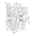
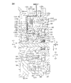
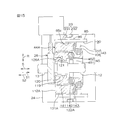
- FIG. 2 is a partial cross-sectional view showing a more specific configuration of the vehicle steering system.
- FIG. 7 is an enlarged view of the vicinity of the opposite end of the first shaft and the second shaft. It is an enlarged view of a transmission ratio variable mechanism and its periphery.
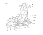
- FIG. 5 is a partial cross-sectional view of the periphery of the lock mechanism, taken along the line VV of FIG. 4; It is an enlarged view of the circumference of a torque sensor.
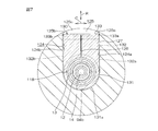
- FIG. 7 is a cross-sectional view taken along the line VIIA-VIIA of FIG.
- SYMBOLS 1 Steering device for vehicles, 2 ... Steering member, 5 ... Transmission ratio variable mechanism (differential mechanism), 10 ... Steering mechanism, 11 ... 1st shaft (1st axis
- steering angle sensor predetermined sensor, steering state detection sensor, rotation angle detection Sensor
- outer cylinder 90 housing space 93 inner cylinder 94 connection wall 108 resolver stator 112, 112A annular portion 116 117 magnetic yoke (signal detection portion) 119 120 ... magnetism collecting ring ( Detection part), 121 ... Hall IC (signal detection part) 122, 122A ... electromagnetic shield member, 123 ... holding hole, 132 ... second synthetic resin part (radially extending part), 231 ... (transmission ratio Rotor for variable mechanism motor, 452 (Stator angle sensor) Stator (for signal detection)
- D Power transmission path
- F1 Receiving direction
- S Axial direction
- ⁇ r (Rotor's) rotation angle
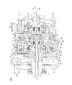
- FIG. 1 is a schematic view showing a schematic configuration of a vehicle steering system 1 including a transmission ratio variable mechanism according to an embodiment of the present invention.
- the vehicle steering device 1 performs steering by applying a steering torque applied to the steering member 2 such as a steering wheel to each of the left and right steered wheels 4L and 4R via the steering shaft 3 and the like. It has a VGR (Variable Gear Ratio) function that can change the transmission ratio ⁇ 2 / ⁇ 1 of the turning angle ⁇ 2 of the steered wheels with respect to the steering angle ⁇ 1 of the steering member 2.
- VGR Vehicle Gear Ratio
- the vehicle steering system 1 includes a steering member 2 and a steering shaft 3 connected to the steering member 2.
- the steering shaft 3 includes first to third shafts 11 to 13 coaxially arranged with one another.
- a first axis A which is a central axis of the first to third shafts 11 to 13, is also a rotation axis of the first to third shafts 11 to 13.
- the axial direction S of the steering shaft 3 is simply referred to as “axial direction S”
- the radial direction R of the steering shaft 3 is simply referred to as “radial direction R”
- the circumferential direction C of the steering shaft 3 is simply “peripheral It is called "direction C”.
- the steering member 2 is rotatably connected to one end of the first shaft 11 in the same direction.
- the other end of the first shaft 11 and one end of the second shaft 12 are differentially rotatably coupled via a transmission ratio variable mechanism 5 as a differential mechanism.
- the other end of the second shaft 12 and one end of the third shaft 13 are elastically connected rotatably relative to each other via a torsion bar 14 so that power can be transmitted.
- one end refers to an end close to the steering member 2 and “the other end” refers to an end close to the steering mechanism 10.
- the other end of the third shaft 14 is connected to the steered wheels 4L and 4R via the universal joint 7, the intermediate shaft 8, the universal joint 9, the steering mechanism 10, and the like.
- the steering mechanism 10 has a pinion shaft 15 connected to the universal joint 9 and a rack shaft 16 having a rack 16a meshing with a pinion 15a at the tip of the pinion shaft 15 and extending in the left-right direction of the vehicle. doing.
- Knuckle arms 18L and 18R are connected to the pair of ends of the rack shaft 16 via tie rods 17L and 17R, respectively.
- the rotation of the steering member 2 is transmitted to the steering mechanism 10 via the steering shaft 3 and the like.
- the rotation of the pinion 15a is converted into the movement of the rack shaft 16 in the axial direction.
- the axial movement of the rack shaft 16 is transmitted to the corresponding knuckle arms 18L and 18R via the tie rods 17L and 17R, and these knuckle arms 18L and 18R rotate respectively.
- the corresponding steered wheels 4L, 4R connected to the knuckle arms 18L, 18R are steered respectively.
- the transmission ratio variable mechanism 5 is for changing the rotation transmission ratio (transmission ratio ⁇ 2 / ⁇ 1) between the first and second shafts 11 and 12 of the steering shaft 3.
- the transmission ratio variable mechanism 5 includes an input member 20 provided at the other end of the first shaft 11, an output member 22 provided at one end of the second shaft 12, an input member 20 and an output member 22. And an orbital ring unit 39 interposed therebetween.
- the input member 20 is coaxially and coaxially connected to the first shaft 11, and the output member 22 is coaxially and coaxially connected to the second shaft 12.
- the first axis A is also a central axis and a rotational axis of the input member 20 and the output member 22.
- the output member 22 is connected to the steered wheels 4L and 4R via the second shaft 12 and the steering mechanism 10 and the like.
- the bearing ring unit 39 has a second axis B as a central axis inclined with respect to the first axis A, and an inner ring 391 as a first bearing ring and an outer ring as a second bearing ring And 392 and rolling elements 393 such as balls interposed between the inner ring 391 and the outer ring 392.
- the inner ring 391 couples the input member 20 and the output member 22 in a differentially rotatable manner, engages with the input member 20 in a rotatable manner, and engages with the output member 22 in a rotatable manner.
- the inner race 391 is rotatably supported by the outer race 392 via the rolling elements 393, and is therefore rotatable around the second axis B.
- a motor for variable transmission ratio mechanism 23 as an actuator for driving the outer ring 392 is provided.
- the outer ring 392 can rotate around the first axis A as the variable transmission ratio motor 23 is driven.
- the inner ring 391 is capable of Coriolis movement (swinging movement) around the first axis A.
- the transmission ratio variable mechanism motor 23 is a brushless motor coaxially disposed with the steering shaft 3, and coaxially disposed with the first and second shafts 11 and 12 to drive the transmission ratio variable mechanism 5. It is done.
- the first axis A is also a central axis of the first and second shafts 11 and 12.
- the transmission ratio variable mechanism motor 23 changes the transmission ratio ⁇ 2 / ⁇ 1 by changing the number of revolutions of the outer ring 392 about the first axis A.
- the transmission ratio variable mechanism motor 23 includes a cylindrical rotor 231 for holding the bearing ring unit 39, and a stator 232 that surrounds the rotor 231 and is fixed to the housing 24.
- the vehicle steering system 1 further includes a steering assist force application mechanism 19 for applying a steering assist force to the steering shaft 3.
- the steering assist force application mechanism 19 includes the second shaft 12 as an input shaft connected to the output member 22 of the transmission ratio variable mechanism 5 and the third shaft as an output shaft connected to the steering mechanism 10.
- a torque sensor 44 which is a steering state detection sensor for detecting a torque transmitted between the second shaft 12 and the third shaft 13
- a steering assist motor 25 as an actuator for steering assist
- a speed reduction mechanism 26 interposed between the steering assist motor 25 and the third shaft 13 is included.
- the steering assist motor 25 is an electric motor such as a brushless motor.
- the output of the steering assist motor 25 is transmitted to the third shaft 13 via the reduction mechanism 26.
- the reduction mechanism 26 is, for example, a worm gear mechanism.
- the reduction mechanism 26 is a worm shaft 27 as a drive gear connected to the output shaft 25 a of the steering assist motor 25 and a driven gear engaged with the worm shaft 27 and rotatably connected to the third shaft 13. And a worm wheel 28.
- the transmission ratio variable mechanism 5 and the steering assist force application mechanism 19 are accommodated in a housing 24.
- the housing 24 is disposed in a passenger compartment (cabin) of the vehicle.
- the housing 24 may be disposed to surround the intermediate shaft 8 or may be disposed in the engine room of the vehicle.
- the drive of the transmission ratio variable mechanism motor 23 and the steering assist motor 25 is controlled by a control unit 29 including a CPU, a RAM and a ROM, respectively.
- the control unit 29 is connected to the transmission ratio variable mechanism motor 23 via the drive circuit 40, and is connected to the steering assist motor 25 via the drive circuit 41.
- the control unit 29 includes a steering angle sensor 42, a motor resolver 43 as a rotation angle detection sensor that detects a rotation angle of the rotor 231 of the transmission ratio variable mechanism motor 23, a torque sensor 44, a turning angle sensor 45, and a vehicle speed sensor 46. And the yaw rate sensor 47 are connected.
- a signal about the rotation angle of the first shaft 11 is input from the steering angle sensor 42 to the control unit 29 as a value corresponding to the steering angle ⁇ 1 which is an operation amount from the straight movement position of the steering member 2.
- a signal about the rotation angle ⁇ r of the rotor 231 of the transmission ratio variable mechanism motor 23 is input from the motor resolver 43 to the control unit 29.
- a signal about torque acting between the second and third shafts 12 and 13 is input from the torque sensor 44 to the control unit 29 as a value corresponding to the steering torque T acting on the steering member 2.
- a signal about the rotation angle of the third shaft 13 is input from the turning angle sensor 45 to the control unit 29 as a value corresponding to the turning angle ⁇ 2.
- a signal about the vehicle speed V is input from the vehicle speed sensor 46 to the control unit 29.
- a signal about the yaw rate ⁇ of the vehicle is input from the yaw rate sensor 47 to the control unit 29.
- the control unit 29 controls the drive of the transmission ratio variable mechanism motor 23 and the steering assist motor 25 based on the signals of the sensors 42 to 47 and the like.
- the torque from the steering member 2 and the torque from the transmission ratio variable mechanism 5 are transmitted to the steering mechanism 10 via the steering assist force application mechanism 19.
- the steering torque input to the steering member 2 is input to the input member 20 of the variable transmission ratio mechanism 5 via the first shaft 11, and is input to the inner race 391 from the input member 20.
- the torque from the transmission ratio variable mechanism motor 5 transmitted to the inner ring 391 via the outer ring 392 and the rolling element 393 is transmitted to the inner ring 391, and these torques are output member It is transmitted to 22.
- the torque transmitted to the output member 22 is transmitted to the second shaft 12.
- the torque transmitted to the second shaft 12 is transmitted to the torsion bar 14 and the third shaft 13, and combined with the output from the steering assist motor 25, via the universal joint 7, the intermediate shaft 8 and the universal joint 9. Is transmitted to the steering mechanism 10.
- the power transmission path D for transmitting the torque of the steering member 2 to the steering mechanism 10 is configured.
- the power transmission path D includes a first shaft 11, an input member 20, an inner ring 391, an output member 22, a second shaft 12, a torsion bar 14 and a third shaft 13, a universal joint 7, an intermediate shaft 8, and a universal joint. It is a route passing through nine.
- FIG. 2 is a partial sectional view showing a more specific structure of the main part of FIG.
- the housing 24 is formed in a cylindrical shape as a whole using, for example, a metal such as an aluminum alloy, and includes first to third housings 51 to 53.
- the first housing 51 has a tubular shape.
- the first housing 51 constitutes a differential mechanism housing that accommodates the transmission ratio variable mechanism 5 as a differential mechanism, and accommodates the transmission ratio variable mechanism motor 23 in cooperation with the second housing 52. Constitute a motor housing.
- One end of the first housing 51 is covered by an end wall member 54.
- One end of the first housing 51 and the end wall member 54 are fixed to each other using a fastening member 55 such as a bolt.
- An annular convex portion 57 at one end of the second housing 52 is fitted to the inner peripheral surface 56 at the other end of the first housing 51.
- the first and second housings 51 and 52 are fixed to each other using a fastening member (not shown) such as a bolt.
- the second housing 52 is cylindrical.
- the second housing 52 constitutes a sensor housing accommodating the torque sensor 44, a resolver housing accommodating the motor resolver 43, and a part of the motor housing accommodating the transmission ratio variable mechanism motor 23.
- the second housing 52 accommodates a bus bar 99 described later and a lock mechanism 58 for locking the rotor 231 of the transmission ratio variable mechanism motor 23.
- the inner peripheral surface 60 of one end of the third housing 53 is fitted to the outer peripheral surface 59 of the other end of the second housing 52.
- the third housing 53 has a tubular shape, and constitutes a speed reduction mechanism housing that accommodates the speed reduction mechanism 26.
- An end wall portion 61 is provided at the other end of the third housing 53.
- the end wall 61 is annular and covers the other end of the third housing 53.
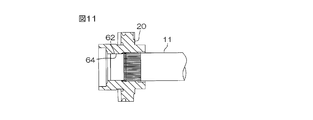
- FIG. 3 is an enlarged view of the vicinity of the opposing ends 11 b and 12 a of the first shaft 11 and the second shaft 12 of FIG. 2. Referring to FIG. 3, the input member 20, the output member 22 and the bearing ring unit 39 of the variable transmission ratio mechanism 5 are each formed in an annular shape.
- the input member 20 is integrally formed as a whole using a single member, and includes an input member main body 201 and an input member side cylindrical portion 202 disposed radially inward of the input member main body 201. There is.
- the input member main body 201 is rotatably supported by an annular convex portion 92 described later of the first housing 51 via the first bearing 31.
- the first shaft 11 is inserted into the input member-side tubular portion 202, so that the input member-side tubular portion 202 and the first shaft 11 are rotatably coupled together.
- the other end 11b of the first shaft 11 includes a press-fit portion 62 formed of a cylindrical surface, and a male serration portion 63 disposed on one side S1 in the axial direction S with respect to the press-fit portion 62.
- the inner peripheral surface of the input member side cylindrical portion 202 is a pressed-in portion 64 formed of a cylindrical surface, a female serration portion 65 disposed on one S1 side in the axial direction S with respect to the pressed-in portion 64, and a female serration.
- a large diameter portion 66 which is disposed on one S1 side in the axial direction S with respect to the portion 65 and is formed larger in diameter than the outer diameter of the first shaft 11 is included.
- the male serration portion 63 of the first shaft 11 is continuously disposed on one side S1 side in the axial direction S with respect to the guide portion 67 connected to the press-fit portion 62 and the guide portion 67, and the male serration portion having a constant outer diameter And a main body 68.
- the guide portion 67 of the first shaft 11 is a guide when inserting the male serration portion 63 into the female serration portion 65.
- the outer diameter of the guide portion 67 increases as it proceeds to one S1 side in the axial direction S, and the minimum diameter of the guide portion 67 is approximately equal to the outer diameter of the press-fit portion 62, and the maximum diameter is the male serration portion main body It is approximately equal to the outer diameter of 68.
- the male serrations 63 are relatively long, and the press-in portions 62 are relatively short.
- the length of the press-fit portion 64 of the input member 20 in the axial direction S is substantially the same as that of the press-fit portion 62.
- the first shaft 11 and the input member 20 are rotatably coupled together by press-fitting and fixing the press-fit portion 62 and the press-fit portion 64 to each other.
- the allowable transmission torque between the press-fit portion 62 and the press-fit portion 64 is, for example, about 20 N ⁇ m, and the torque is transmitted between the press-fit portion 62 and the press-fit portion 64 in a normal steering state. Ru.
- the length of the female serration portion 65 of the input member 20 in the axial direction S is substantially the same as that of the male serration portion 63, and is engaged with the male serration portion 63.
- a predetermined gap is provided in the circumferential direction C between the teeth of these serrations 63 and 65, and torque is not transmitted between these serrations 63 and 65 in the normal steering state. ing.
- an extremely large reverse input acts from each of the steered wheels 4L and 4R, and this reverse input is transmitted between the input member 20 and the first shaft 11 via the third shaft 13 or the like, and the press-fit portion 64
- a torque for example, 200 N ⁇ m to 300 N ⁇ m
- slippage occurs between the press-fit portion 64 and the press-fit portion 62.
- the teeth of the serrations 63, 65 mesh with each other. At this time, torque is transmitted between the serration portions 63 and 65, whereby torque is transmitted between the input member 20 and the first shaft 11.
- the output member 22 is integrally formed as a whole using a single member, and includes an output member main body 221 and an output member side cylindrical portion 222 disposed radially inward of the output member main body 221. There is.
- the output member main body 221 is rotatably supported by the tip of an inner cylinder 93 described later of the second housing 52 via the third bearing 33.
- the second shaft 12 is inserted into the output member side cylindrical portion 222, and the output member side cylindrical portion 222 and the second shaft 12 are connected to be rotatable together.
- the middle portion 12b of the second shaft 12 includes a press-fit portion 62 formed of a cylindrical surface and a male serration portion 63 disposed on the other side S2 in the axial direction S with respect to the press-fit portion 62. There is.
- the inner peripheral surface of the output member side cylindrical portion 222 is a pressed-in portion 64 formed of a cylindrical surface, a female serration portion 65 disposed on the other side S2 in the axial direction S with respect to the pressed-in portion 64, and a female serration. It includes a large diameter portion 66 which is disposed on the other side S 2 in the axial direction S with respect to the portion 65 and is formed larger in diameter than the outer diameter of the middle portion 12 b of the second shaft 12.
- the outer diameter of the one end 12a of the second shaft 12 is smaller than the minimum diameter of the inner peripheral surface of the output member 22, and the one end 12a can be loosely fitted to the output member side cylindrical portion 222 There is.
- the male serration portion 63 of the second shaft 12 is continuously disposed on the guide portion 67 connected to the press-fit portion 62 of the second shaft 12 and on the other S2 side in the axial direction S with respect to the guide portion 67. And a male serration body 68 having a constant diameter.
- the guide portion 67 of the second shaft 12 is a guide when the male serration portion 63 is inserted into the female serration portion 65.
- the outer diameter of the guide portion 67 of the second shaft 12 increases as it proceeds to the other S2 side in the axial direction S, and the minimum diameter of the guide portion 67 is approximately equal to the outer diameter of the press-fit portion 62, and the maximum diameter Is approximately equal to the outer diameter of the male serration portion body 68.
- the male serrations 63 are relatively long, and the press-in portions 62 are relatively short.
- the length of the press-fit portion 64 of the output member 22 in the axial direction S is substantially the same as that of the press-fit portion 62.
- the second shaft 12 and the output member 22 are rotatably coupled together by press fitting and fixing the press-fit portion 62 and the press-fit portion 64 to each other.
- the allowable transmission torque between the press-fit portion 62 and the press-fit portion 64 is, for example, about 20 N ⁇ m, and in a normal steering state, the torque is transmitted between the press-fit portion 62 and the press-fit portion 64. Be done.
- the length of the female serration portion 65 of the output member 22 in the axial direction S is substantially the same as that of the male serration portion 63 of the second shaft 12, and is fitted to the male serration portion 63.
- a predetermined gap is provided in the circumferential direction C between the teeth of these serrations 63 and 65, and torque is not transmitted between these serrations 63 and 65 in the normal steering state. ing.
- an extremely large reverse input acts from each of the steered wheels 4L and 4R, and this reverse input is transmitted between the output member 22 and the second shaft 12 via the third shaft 13 or the like, and the press-fit portion 64
- a torque for example, 200 N ⁇ m to 300 N ⁇ m
- slippage occurs between the press-fit portion 64 and the press-fit portion 62.
- the teeth of the serrations 63, 65 mesh with each other. At this time, torque is transmitted between the serration portions 63 and 65, whereby torque is transmitted between the output member 22 and the second shaft 12.
- the gaps between the teeth of the serrations 63 and 65 may be closed to lightly press each other's teeth (light pressure contact).
- the power transmission surface 73 and the first end surface 75 face each other in the axial direction S of the steering shaft 3.
- a first uneven engaging portion 71 is provided on each of the input member main body 201 and the inner ring 391.
- the inner race 391 and the output member 22 can transmit power by being provided with the second uneven engagement portion 72 in each of the inner race 391 and the output member 22.
- the first concavo-convex engaging portion 71 is formed on a first convex portion 74 formed on the power transmission surface 73 as one end surface of the input member main body 201 and a first end surface 75 as one end surface of the inner ring 391. And a first recess 76 engaged with the first protrusion 74.
- the first protrusions 74 are formed at equal intervals all around the input member 20.
- the first recesses 76 are formed at equal intervals all around the inner ring 391.
- the first axis 74 of the first convex portion 74 When the second axis B of the inner ring 391 is inclined at a predetermined angle E with respect to the first axis A of the input member 20 and the output member 22, the first axis 74 of the first convex portion 74 The convex portion 74 of 1 and the first concave portion 76 of a part of the first concave portions 76 mesh with each other.
- the number of first protrusions 74 is different from the number of first recesses 76. Depending on the difference between the number of first projections 74 and the number of first recesses 76, differential rotation can be generated between the input member 20 and the inner ring 391.
- “rollers” formed separately from the input member main body 201 may be used instead of the first convex portion 74.
- the "rollers” are disposed on the power transmission surface 73 and both ends are rotatably supported by the cage.
- the power transmission surface 77 and the second end surface 79 face each other in the axial direction S of the steering shaft 3.
- the second uneven engagement portion 72 is formed on a second convex portion 78 formed on the power transmission surface 77 as one end surface of the output member 22 and on a second end surface 79 as the other end surface of the inner ring 391.
- a second recess 80 engaged with the second protrusion 78.
- the second convex portion 78 of the second concavo-convex engaging portion 72 has the same configuration as the first convex portion 74, and the second concave portion 80 has the same configuration as the first concave portion 76. Have. Therefore, the description of the details of the second uneven engagement portion 72 is omitted.
- the opposing ends 11 b and 12 a of the first shaft 11 and the second shaft 12 are coaxially and relatively rotatably supported by a support mechanism 81.
- the support mechanism 81 includes the above-described input member side cylindrical portion 202 and an eighth bearing 38.
- the input member side cylinder portion 202 surrounds the facing end portions 11 b and 12 a of the first and second shafts 11 and 12, respectively.
- One end of the input member side cylindrical portion 202 is opposed to the first bearing 31 in the radial direction R.
- the other end of the input member side cylindrical portion 202 is opposed to the opposite end 12 a of the second shaft 12 in the radial direction R.
- a bearing holding hole 84 is formed at the other end of the input member side cylindrical portion 202, and the opposite end 12a of the second shaft 12 is inserted through the bearing holding hole 84.
- An eighth bearing 38 intervenes between the facing end 12a of the second shaft 12 and the bearing holding hole 84 to allow relative rotation between the input member side cylindrical portion 202 and the second shaft 12 .
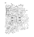
- FIG. 4 is an enlarged view of the transmission ratio variable mechanism 5 of FIG. 2 and the periphery thereof.
- the rotor 231 of the transmission ratio variable mechanism motor 23 includes a cylindrical rotor core 85 extending in the axial direction S, and a permanent magnet 86 fixed to the outer peripheral surface of the rotor core 85.
- the axial direction S is also the axial direction of the rotor 231.
- the material of the rotor core 85 can be exemplified by steel, aluminum alloy, clad material, and resin material. In the case of using a clad material which is a composite material in which a plurality of types of metals are bonded, resonance can be suppressed.
- the rotor core 85 is accommodated in an outer cylinder 89 formed by the cooperation of the outer diameter portions 87 and 88 of the first and second housings 51 and 52.
- Each outer shape portion 87, 88 has a substantially cylindrical shape, and is continuously formed adjacent to each other in the axial direction S.
- the outer periphery of the rotor core 85 is surrounded by the outer cylinder 89.
- the rotor core 85 defines a cylindrical accommodation space 90 radially inward.
- the inner peripheral surface of the rotor core 85 is formed with an inclined hole 91 which is inclined with respect to the first axis A, with the second axis B as a central axis.
- the outer ring 392 of the bearing ring unit 39 is press-fitted and fixed to the inclined hole 91, whereby the outer ring 392 and the rotor core 85 are coupled together rotatably around the first axis A.
- the rotor core 85 is supported on both sides by the second bearing 32 and the fourth bearing 34.
- the second bearing 32 is disposed between the inner peripheral surface of the one end portion 85 a of the rotor core 85 and the outer peripheral surface of the annular convex portion 92 formed on the inner diameter portion of one end of the first housing 51. It is done.
- the fourth bearing 34 is disposed between the inner peripheral surface of the intermediate portion 85 c of the rotor core 85 and the outer peripheral surface of the tip of the inner cylinder 93 of the second housing 52.
- the inner cylinder 93 is formed in a cylindrical shape and extends to one S1 side in the axial direction S, the middle portion and the tip portion are disposed in the housing space 90 of the rotor core 85, and the base end portion with respect to the rotor core 85 And protrudes toward the other side S2 in the axial direction S.
- the proximal end of the inner cylinder 93 is extended from the inner diameter of the annular connecting wall 94.
- the connection wall 94 extends inward in the radial direction R from a portion of the outer cylinder 89 on the outer diameter portion 87 side of the second housing 52 and is adjacent to the other end 85 b of the rotor core 85 in the axial direction S doing.
- the connection wall 94 covers the other end of the second housing 52.
- the permanent magnets 86 of the rotor 231 have different magnetic poles alternately in the circumferential direction C, and with respect to the circumferential direction C, N poles and S poles are alternately disposed at equal intervals.
- the permanent magnet 86 is fixed to the outer peripheral surface of the middle portion 85 c of the rotor core 85.
- the stator 232 of the transmission ratio variable mechanism motor 23 includes an annular stator core 95 formed by laminating a plurality of electromagnetic steel plates, and an electromagnetic coil 96.
- the outer peripheral surface of the stator core 95 is fixed to the inner peripheral surface of the outer diameter portion 87 of the first housing 51 by shrink fitting or the like.
- An electromagnetic coil 96 is wound around each tooth of the stator core 95.
- a bus bar 99 is disposed on the other side S 2 in the axial direction S with respect to the stator 232 of the variable transmission ratio motor 23.
- the bus bar 99 is accommodated in the second housing 52 in an annular shape as a whole, and is connected to each electromagnetic coil 96 of the transmission ratio variable mechanism motor 23.
- the bus bar 99 supplies power from the drive circuit to each electromagnetic coil 96.
- a harness (not shown) for transmitting a signal to the outside of the housing 24 is attached to the bus bar 99.
- FIG. 5 is a partial cross-sectional view of the periphery of the lock mechanism 58, taken along the line VV of FIG. Referring to FIGS. 4 and 5, lock mechanism 58 engages lock holder 100 as a restricted portion coupled rotatably together with rotor core 85, and rotation of lock folder 100 by engaging lock folder 100. And a solenoid 102 as an actuator for driving the lock lever 101. As shown in FIG.
- the lock folder 100 is formed by cutting a metal annular member.
- a recess 103 is formed on the outer peripheral surface of the lock folder 100.
- Recesses 103 are formed at one or more locations in the circumferential direction of lock folder 100.
- the lock lever 101 is a lever member extending inward from the outside of the second housing 52, and the proximal end is disposed close to the solenoid 102 and the distal end is disposed close to the lock folder 100.
- the lock lever 101 is inserted through a through hole 104 penetrating the second housing 52 in the radial direction R, and is not in contact with the second housing 52.
- the rod 102 a of the solenoid 102 is connected to the proximal end of the lock lever 101.
- a support shaft insertion hole 101a is formed in an intermediate portion on the base end side of the lock lever 101, and a support shaft 105 held in the second housing 52 and extending in the axial direction S is formed in the support shaft insertion hole 101a. It is inserted.
- the lock lever 101 is rotatably supported around the support shaft 105 by the support shaft 105.
- the tip of the lock lever 101 is formed using an elastic member 101 b.
- the elastic member 101 b is for reducing an engagement noise when the lock lever 101 engages with the lock folder 100 to restrict the rotation of the lock folder 100, and is made of, for example, a synthetic resin such as a thermoplastic elastomer. It is formed using.
- the elastic member 101b has a convex shape that can be fitted into the concave portion 103 of the lock folder 100, and has a higher elasticity than the metal main portion 101c that constitutes the base end portion and the middle portion of the lock lever 101. have.
- the elastic member 101 b is formed by injection molding on the front end surface 101 d of the main body portion 101 c.
- the engagement convex portion 101e formed at the proximal end of the elastic member 101b is fitted into the engagement concave portion 101f formed at the distal end of the main portion 101c, whereby the elastic member 101b and the main portion 101c are sufficiently coupled.
- the strength is secured.
- An engagement recess may be formed at the base end of the elastic member 101b, and an engagement projection may be formed at the distal end of the main body 101c, and both may be fitted.
- the solenoid 102 has a solenoid housing 102b fixed to the second housing 52, and a rod 102a supported by the solenoid housing 102b is movable forward and backward with respect to the solenoid housing 102b.
- the proximal end of the lock lever 101 is connected to the tip of the rod 102a.
- the rod 102a is in a state of being drawn into the solenoid housing 102b while energization of an electromagnetic coil (not shown) accommodated in the solenoid housing 102b is turned on.
- the base end of the lock lever 101 is pulled toward the solenoid housing 102 b, and the elastic member 101 b at the tip of the lock lever 101 does not engage with the lock folder 100.
- the rotation of the lock folder 100 is not restricted.
- the rod 102a protrudes from the solenoid housing 102b as indicated by a two-dot chain line.
- the lock lever 101 is pivoted, and the elastic member 101b is engaged with the recess 103 of the lock folder 100. Regulate the rotation of 100.
- the motor resolver 43 is disposed on the other side S ⁇ b> 2 in the axial direction S with respect to the lock mechanism 58.
- the motor resolver 43 includes a resolver rotor 107 and a resolver stator 108.
- the resolver rotor 107 is fixed to the outer peripheral surface of the other end 85 b of the rotor core 85.
- the resolver stator 108 includes an annular stator core 109 press-fitted and fixed to the inner peripheral surface of the outer diameter portion 88 of the second housing 52, and an electromagnetic coil 110.
- the electromagnetic coil 110 is wound around each tooth of the stator core 109.
- the above-described bus bar 99 is connected to each electromagnetic coil 110 of the resolver stator 108.
- the bus bar 99 is configured to output a signal from each electromagnetic coil 110 to the control unit.
- the lock mechanism 58 and the bus bar 99 are arranged such that positions in the axial direction S overlap with each other while avoiding interference with each other.
- the lock folder 100 and the lock lever 101 of the lock mechanism 58 and a part of the bus bar 99 are arranged such that the positions in the axial direction S overlap each other.
- the bus bar 99 is disposed in an area excluding the movable area 111 of the lock lever 101.
- torque sensor 44 constitutes a steering state detection sensor for detecting a steering state, and detects torque acting between the second and third shafts 12 and 13 on the power transmission path.
- a part of the torque sensor 44 is accommodated in the accommodation space 90 on the other end 85 b side of the rotor core 85 of the transmission ratio variable mechanism motor 23.
- the torque sensor 44 is supported by a multipole magnet 115 fixed to the middle portion of the second shaft 12 and one end of the third shaft 13, and is disposed in a magnetic field generated by the multipole magnet 115 to provide a magnetic circuit And magnetic yokes 116 and 117 which are signal detection portions as a pair of soft magnetic bodies.
- the multipolar magnet 115 is a cylindrical permanent magnet, and a plurality of poles (the same number of poles as each of N and S) are magnetized at equal intervals in the circumferential direction.
- the magnetic yokes 116 and 117 face the multipolar magnet 115 with a predetermined gap in the radial direction R, and surround the multipolar magnet 115.
- Each of the magnetic yokes 116 and 117 is molded in a synthetic resin member 118.
- the synthetic resin member 118 is rotatably connected to one end of the third shaft 13.
- the torque sensor 44 further includes an annular portion 112.
- the annular portion 112 surrounds the multipolar magnet 115, the magnetic yokes 116 and 117, the second shaft 12 and the third shaft 13.
- the annular portion 112 has an annular shape as a whole, and a pair of magnet collection rings 119 and 120 as signal detection parts for inducing magnetic flux from the magnetic yokes 116 and 117 and between the magnet collection rings 119 and 120.
- Hall IC (Hall IC) 121 as a signal detection portion disposed, electromagnetic shielding member 122 surrounding a pair of magnetic flux collecting rings 119 and 120 and Hall IC 121, magnetic flux collecting rings 119 and 120, Hall IC 121 and electromagnetic shielding member And an annular first synthetic resin portion 131 for molding 122.
- the pair of magnet collection rings 119 and 120 are annular members formed using a soft magnetic material, and are magnetically coupled to the magnetic yokes 116 and 117 surrounding the magnetic yokes 116 and 117, respectively.
- the pair of magnet collection rings 119 and 120 are separated in the axial direction S and opposed to each other.
- the Hall IC 121 is for detecting the magnetic flux induced in the magnet collection rings 119 and 120.
- the electromagnetic shield member 122 is an annular member disposed between the magnetic yokes 116 and 117 of the torque sensor 44, the magnetic flux collecting rings 119 and 120, and the Hall IC 121 and the rotor core 85 of the rotor 231. Noise is prevented from passing inside the electromagnetic shield member 122.
- the electromagnetic shield member 122 is preferably formed of a material having a large magnetic loss or a material having a high conductivity. For example, ferrite can be mentioned as a material having a large magnetic loss, and copper and aluminum can be mentioned as a material having a high conductivity.
- the thickness of the electromagnetic shield member 122 is set to a thickness that can effectively suppress the entry of electromagnetic noise.
- the electromagnetic shield member 122 is disposed inward with respect to both the rotor core 85 of the rotor 231 and the motor resolver 43 in the radial direction R. Further, the electromagnetic shield member 122 is disposed closer to the permanent magnet 86 in the axial direction S than the magnet collection rings 119 and 120 and the Hall IC 121. Thus, the electromagnetic shield member 122 is disposed between the magnetic yokes 116 and 117, the magnetic flux collecting rings 119 and 120, the Hall IC 121, and the permanent magnet 86.
- FIG. 7 is a cross-sectional view taken along the line VIIA-VIIA of FIG. 6, and FIG. 8 is a side view of the main part of the torque sensor 44.
- the first synthetic resin portion 131 together with a second synthetic resin portion 132, a third synthetic resin portion 133, and a fourth synthetic resin portion 134, which will be described later,
- the synthetic resin member 130 which is an integral molded product of synthetic resin which has the characteristic insulation property is comprised.
- the position with respect to the axial direction S is overlapped with most of the one side S1 side in the axial direction S and the other end 85b of the rotor core 85, and the other S2 side in the axial direction S
- the end portion protrudes to the other S2 side in the axial direction S with respect to the other end portion 85b of the rotor core 85.
- the outer peripheral surface 131 a of the first synthetic resin portion 131 is press-fitted and held in the holding hole 123 of the inner cylinder 93 of the second housing 52.
- the annular portion 112 is held in the holding hole 123.
- the holding hole 123 is open in the axial direction S.
- the holding hole 123 can receive the first synthetic resin portion 131 from the other S2 side (lower side) of the axial direction S along a predetermined receiving direction F1 along one of the axial direction S.
- the second synthetic resin portion 132 is a radially extending portion extended from the end on the other S2 side in the axial direction S of the first synthetic resin portion 131 along the outer side in the radial direction R. Configured.
- the second synthetic resin portion 132 is formed in a flat plate shape extending outward in the radial direction R from a part of the first synthetic resin portion 131 in the circumferential direction C, and is adjacent to the rotor core 85 in the axial direction S doing.
- the second synthetic resin portion 132 is inserted into the first groove 124 of the second housing 52.
- the first groove 124 is formed in one end surface 94a of the connection wall 94 of the second housing 52 facing the direction F2 opposite to the receiving direction F1, and is opened in the direction F2 opposite to the receiving direction F1.
- the second synthetic resin portion 132 can be received along the receiving direction F1.
- the first groove 124 is formed in a part of the end face 94 a in the circumferential direction C.
- the first groove 124 includes a pair of inner side surfaces 124a and 124b which are separated from each other in the circumferential direction C and extend in parallel to each other, and between the pair of inner side surfaces 124a and 124b, the second synthetic resin portion 132 It is arranged.
- the base end portion of the second synthetic resin portion 132 is disposed inward in the radial direction R with respect to the rotor core 85, and the tip end portion is disposed outward in the radial direction R with respect to the rotor core 85.
- the third synthetic resin portion 133 constitutes an axially extending portion which is extended from the end of the second synthetic resin portion 132 to one S1 side in the axial direction S.
- the third synthetic resin portion 133 extends from the tip of the second synthetic resin portion 132 in the receiving direction F1 and is formed on the outer diameter portion 88 side of the second housing 52 in the outer cylinder 89. Is accommodated in the second groove 125.
- the second groove 125 is in communication with the first groove 124, extends to one S1 side in the axial direction S with respect to the first groove 124, and is opened outward in the radial direction R.
- the second groove 125 and the third synthetic resin portion 133 overlap at least a part (generally all in the present embodiment) of the annular portion 112 with respect to the axial direction S.
- the fourth synthetic resin portion 134 has an arc shape projecting from the first synthetic resin portion 131 in the second axial direction S2.
- the inner circumferential surface 134a of the fourth synthetic resin portion 134 is continuously formed on the inner circumferential surface 94b of the connection wall 94, and cooperates with the inner circumferential surface 96b to form the outer ring of the fifth bearing 35.
- the outer peripheral surface is held over the entire circumference.
- an electric wire 126 for transmitting a signal from the Hall IC 121 to the control unit is embedded.
- the electric wire 126 has one end electrically connected to the Hall IC 121 and extends from the first synthetic resin portion 131 of the annular portion 112 to the second synthetic resin portion 132 and the third synthetic resin portion 133.
- the electric wire 126 protrudes from the synthetic resin member 130 at the annular portion 112 and is electrically connected to the control unit.
- the synthetic resin member 130 further includes a sealing portion 127 which seals between the first groove 124 of the second housing 52 and the second groove 125 in a liquid tight manner.
- the sealing portion 127 is formed in an elongated ring shape, and an outer peripheral surface 131 a of the other end of the first synthetic resin portion 131, a pair of side surfaces 132 a and 132 b of the second synthetic resin portion 132, and a third synthetic resin It protrudes from each of the pair of side surfaces 133a and 133b of the portion 133 and the end surface 133c of the third synthetic resin portion 133.
- the sealing portion 127 is formed by the inner peripheral surface 94 b of the connection wall 94 of the second housing 52, the corresponding inner side surfaces 124 a and 124 b of the first groove 124, and the corresponding inner side surfaces 125 a and 125 b of the second groove 125. , 125c, respectively.
- a magnetic flux is generated in the magnetic yokes 116 and 117 in accordance with the relative rotation amount of the second and third shafts 12 and 13, and the magnetic flux is induced by the magnetic flux collecting rings 119 and 120.
- Hall IC 121 is detected.
- the torque detection signal of the Hall IC 121 is input to the control unit via the electric wire 126. In this manner, the magnetic flux density can be detected in accordance with the torque applied to the second and third shafts 12 and 13.
- the fifth bearing 35 is disposed on the other side S ⁇ b> 2 in the axial direction S with respect to the torque sensor 44.
- the fifth bearing 35 rotatably supports one end of the third shaft 13.
- the outer peripheral portion of the second shaft 12 and the inner peripheral portion of the third shaft 13 are supported relative to each other via a sixth bearing 36 so as to be relatively rotatable.
- the speed reduction mechanism 26 is accommodated in an accommodation chamber 129 formed by the outer diameter portion 128 and the end wall portion 61 of the third housing 53 and the connection wall 94 of the second housing 52.
- the end wall 61 of the third housing 53 rotatably supports the third shaft 13 via a seventh bearing 37.
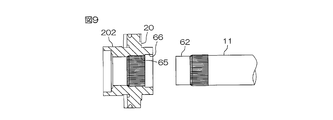
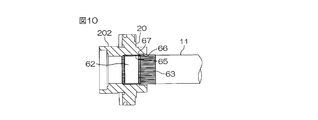
- the connection between the input member 20 and the first shaft 11 is performed as follows. That is, first, as shown in FIG. 9, a single-piece input member 20 and the first shaft 11 are prepared, and the press fit portion 62 of the first shaft 11 faces the input member 20 so that both are coaxial. Make them face each other. Next, as shown in FIG. 10, the first shaft 11 is inserted into the input member side cylindrical portion 202 of the input member 20. Thereby, the press-fit portion 62 is loosely fitted to the large diameter portion 66 and the female serration portion 65 of the input member side cylindrical portion 202. Then, when the guide portion 67 of the male serration portion 63 engages with the female serration portion 65, the both tooth portions are guided so as to be alternately arranged in the circumferential direction.
- the press-fit portion 62 is press-fit into the press-fit portion 64, and the connection of both is completed.
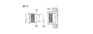
- the connection between the output member 22 and the second shaft 12 is performed as follows. That is, first, as shown in FIG. 12, a single-piece output member 22 and a second shaft 12 are prepared, and the press-fit portion 62 of the second shaft 12 faces the output member 22 so that both are coaxial. Make them face each other.
- the second shaft 12 is inserted into the output member side cylindrical portion 222 of the output member 22.
- the one end 12 a of the second shaft 12 and the press-fit portion 62 are loosely fitted to the large diameter portion 66 and the female serration portion 65 of the output member side cylindrical portion 222.
- the guide portion 67 of the male serration portion 63 engages with the female serration portion 65 the both tooth portions are guided so as to be alternately arranged in the circumferential direction.
- the press-fit portion 62 is press-fit into the press-fit portion 64, and the connection of the both is completed.
- the vehicle steering system 1 having the above-described configuration drives the motor for variable transmission ratio mechanism 23 in the transmission ratio variable mechanism 5.
- the transmission ratio ⁇ 2 / ⁇ 1 By changing the transmission ratio ⁇ 2 / ⁇ 1 to a higher value, it is possible to exhibit a function of amplifying the steering angle ⁇ 1 and assisting the driver's steering.
- the vehicle when the vehicle is traveling at a relatively high speed, by driving the motor for variable transmission ratio mechanism 23 to change the transmission ratio ⁇ 2 / ⁇ 1 in the transmission ratio variable mechanism 5 to a lower value, the vehicle Perform stability control (posture stabilization control).
- the annular portion 112 of the torque sensor 44 and the rotor core 85 of the rotor 231 of the transmission ratio variable mechanism motor 23 can be arranged so as to overlap in the axial direction S.
- the total length of the vehicle steering system 1 can be shortened.
- the annular portion 112 of the torque sensor 44 can be held in the housing space 90 by the inner cylinder 93 of the housing 24. Further, since the annular portion 112 can be inserted into the holding hole 123 of the inner cylinder 93 along the axial direction S (receiving direction F1), the torque sensor 44 can be disposed further to the rear side of the rotor core 85. Space can be used effectively. Further, by providing the second and third synthetic resin portions 132 and 133, the portion connected to the first synthetic resin portion 131 is extended so as to be exposed radially outward of the rotor core 85, and hence from the housing 24. Can. Thus, the electric wire 126 transmitting the torque detection signal can be extended through the first to third synthetic resin portions 131 to 133 to the outside of the housing 24. As a result, the torque detection signal can be transmitted to the control unit outside the housing 24.
- the torque sensor 44 can receive electromagnetic noise from the outside. It can prevent picking up.
- the input member 20 and the output member 22 and the corresponding first and second shafts 11 and 12 are coupled so as to be able to transmit torque by press-fitting and are also connected to be able to transmit torque by serration fitting. .
- the mutual positioning of the first shaft 11 and the input member 20 can be made with high accuracy.
- the mutual positioning of the second shaft 12 and the output member 22 can be made with high accuracy.
- serration coupling of the input member 20 and the first shaft 11 even if a large torque acts, it can be reliably received between the input member 20 and the first shaft 11, It is possible to suppress that the relative phase (position in the circumferential direction) is largely deviated. Thereby, it is possible to suppress the phase shift of the first shaft 11 and the steering member 2 in the steering neutral state, and to prevent the occurrence of discomfort in steering.
- the support mechanism 81 by supporting both the input member 20 and the output member 22 using the eighth bearing 38, the bearing that supports these members 20 and 22 can be shared, and the number of bearings can be reduced. As a result, the manufacturing cost can be reduced through the reduction of the number of parts. That is, three bearings of the first, third and eighth bearings 31, 33 and 38 are sufficient for supporting the input member 20 and the output member 22. Therefore, for example, while supporting the both ends of an input member with a pair of bearings, unlike the case where the both ends of an output member are supported with a pair of bearings different from the pair of bearings, four bearings are prepared. There is no need.
- the space for the bearings for supporting the input member 20 and the output member 22 can be shortened with respect to the axial direction S.
- the length of the axial direction S can be made shorter.
- the eighth bearing 38 is used to prevent inclination (falling) between the opposing end portions 11 b and 12 a of the first and second shafts 11 and 12, the shaft is supported by these shafts 11 and 12. The meshing state of the input member 20 and the output member 22 can be maintained with high accuracy.
- the elastic member 101b at the tip of the lock lever 101 of the lock mechanism 58, the engagement noise at the time of the engagement between the lock lever 101 and the lock folder 100 can be reliably reduced.
- the area in which the elastic member 101b is provided can be reduced as much as possible, and the cost for injection molding can be reduced.
- the shape and manufacturing process of the lock folder 100 can be simplified.
- the lock lever 101, the lock folder 100 and the bus bar 99 of the lock mechanism 58 are disposed between the stator 232 and the resolver stator 108 of the variable transmission ratio motor 23, and the movable region 111 of the lock lever 101 is avoided.
- the bus bar 99 is disposed.
- the wiring for the stator 232, the wiring for the resolver stator 108, and the wiring for the electromagnetic solenoid 102 can be extended from the location close to each other to the outside of the housing 24, and wiring of these wirings can be performed more easily. Furthermore, by providing the sealing portion 127 on the synthetic resin member 130, a lubricant such as grease filled in the meshing region of the worm shaft 27 and the worm wheel 28 of the reduction gear mechanism 26 is synthesized with the second housing 52. Leakage from between the resin member 130 can be prevented. By providing the sealing portion 127 integrally with the synthetic resin member 130, there is no need to separately provide a sealing structure, and as a result, the vehicle steering device 1 can be further shortened in the axial direction S.
- the arrangement space for providing the electric tilt mechanism provided with the electric motor, the tilt telescopic mechanism, and the vehicle A sufficient impact absorption stroke for absorbing the impact at the time of the next collision can be secured. Furthermore, the degree of freedom in the layout of the vehicle steering system 1 in the vehicle compartment can be increased.
- the second housing 52 accommodates the rotor 231 of the transmission ratio variable mechanism motor 23 and has a function as a transmission ratio variable mechanism housing, and a combination of the torque sensor 44 of the steering assist mechanism 19. It holds the annular portion 112 of the resin member 130, and has a function as a steering assist mechanism housing.
- the second housing 52 can be used as the variable transmission ratio mechanism housing and the steering assist mechanism housing, and as a result, the manufacturing cost can be reduced.
- the inner cylinder 93 of the second housing 52 can be formed thin, and the second and fourth bearings 32 and 34 for supporting the rotor core 85 can be disposed in the rotor core 85. A simple configuration can be adopted in which these bearings 32 and 34 are disposed in the rotor core 85, and the manufacturing cost can be further reduced.
- the outer peripheral surface of the rotor core 85 can be formed to be a substantially flat surface, it is possible to reduce the time and effort required for processing the rotor core 85, and the manufacturing cost of the rotor core 85 can be reduced. It can be reduced. Furthermore, since the annular portion 112 of the torque sensor is annular and does not have a shape that protrudes in the radial direction R, the rotor core 85 surrounding the annular portion 112 can be formed to a small diameter. As a result, the second and fourth bearings 32 and 34 for supporting the rotor core 85 can be miniaturized, and the cost of these bearings 32 and 34 can be significantly reduced.
- the present invention is not limited to the contents of the above embodiments, and various modifications are possible within the scope of the present invention.
- the entire torque sensor 44A may be disposed in the housing space 90.
- FIGS. 1 to 9 only differences from the embodiment shown in FIGS. 1 to 9 will be described, and the same reference numerals will be given to the same components as those in the embodiment and the description thereof will be omitted.
- the difference of the present embodiment shown in FIG. 15 from the embodiments shown in FIGS. 1 to 9 is mainly (i) that all of the torque sensor 44A is disposed in the housing space 90 (ii ) A point that all of the turning angle sensor 45 which is a rotation angle detecting sensor as a steering state detecting sensor is disposed in the accommodation space 90, and (iii) a motor resolver which is a rotation angle detecting sensor as a steering state detecting sensor All of the points 43 are disposed in the housing space 90.
- the annular portion 112 ⁇ / b> A of the torque sensor 44 ⁇ / b> A faces the rotor core 85 in the radial direction R over the entire area in the axial direction S.
- An electric wire 126A protrudes from an end of the first synthetic resin portion 131A of the annular portion 112A on the other side S2 in the axial direction S, and is extended to the outside of the housing 24.
- the turning angle sensor 45 is disposed on one S1 side in the axial direction S with respect to the pair of magnetic flux collecting rings 119 and 120, and rotates in the same direction as the second shaft 12 as a predetermined shaft member on the power transmission path.
- the rotation angle of the second shaft 12 is detected, which includes a rotor 451 which is connected in a possible manner, and a stator 452 as a signal detection portion surrounding the rotor 451.
- the stator 452 is held by the first synthetic resin portion 131A by being at least partially embedded in the first synthetic resin portion 131A of the annular portion 112A.
- the signal detected by the stator 452 is input to the control unit via an electric wire (not shown).
- the motor resolver 43 is disposed on the other side S ⁇ b> 2 in the axial direction S with respect to the turning angle sensor 45.
- the resolver rotor 107 of the motor resolver 43 is rotatably connected to the inner peripheral surface of the rotor core 85 in the same direction.
- the resolver stator 108 of the motor resolver 43 constitutes a signal detection unit, and the signal detected by the resolver stator 108 is output to the control unit via an electric wire (not shown).
- the resolver stator 108 is held by the first synthetic resin portion 131A by being at least partially embedded in the first synthetic resin portion 131A.
- the permanent magnet 86 and the stator 232 of the rotor 231 of the transmission ratio variable mechanism 5 are disposed at an intermediate portion 85 c of the rotor core 85.
- the electromagnetic shield member 122A is connected to the first cylindrical portion 141 surrounding the outer periphery of the pair of magnetic flux collecting rings 119 and 120 of the torque sensor 44 and the Hall IC 121, and the stator of the turning angle sensor 45
- the second cylindrical portion 142 surrounding the outer periphery of 452 and extending outward in the radial direction R from one end of the second cylindrical portion 142 are disposed between the permanent magnet 86 of the rotor 231 and the motor resolver 43 And an annular collar portion 143.
- the first and second cylindrical portions 141 and 142 are disposed inward in the radial direction R with respect to the permanent magnet 86.
- the collar portion 143 is disposed between the permanent magnet 86 and the motor resolver 43 in the axial direction S.
- each of the turning angle sensor 45 and the motor resolver 43 can be disposed so as to overlap the rotor core 85 of the rotor 231 in the axial direction S, and the overall length of the device 1 in the axial direction S can be further shortened.
- each of the turning angle sensor 45 and the rotor motor resolver 43 may be disposed in the housing space 90.
Abstract
この伝達比可変機構を備える車両用操舵装置1は、操舵部材に連なる第1のシャフト11及び転舵機構に連なる第2のシャフト12を同軸上に連結した伝達比可変機構5と、伝達比可変機構5を駆動するために第1及び第2のシャフト11,12とは同軸的に配置された伝達比可変機構用モータ23とを備えている。伝達比可変機構用モータ23は筒状のロータ231を含み、このロータ231のロータコア85の径方向内方に収容空間90が規定されている。トルクセンサ44の少なくとも一部が前記収容空間90内に配置されている。車両用操舵装置の全長を短くすることができる。
Description
本発明は、車両用操舵装置に関するものである。
入力回転角に対する出力回転角の比としての伝達比を変化することのできる伝達比可変機構が知られている(例えば、特許文献1~5参照)。
特開平5-105103号公報
特開2004-256087号公報
特開2005-162124号公報
特開2005-67284号公報
特開2007-145067号公報
伝達比可変機構は、たとえば、前記特許文献5の段落番号[0015]に記載されているように、駆動源としてのモータと、差動機構としての波動歯車機構とを備えている。ステアリング操作に伴うステアリングシャフトの回転に、前記のモータ駆動に基づくステアリングシャフトの回転を上乗せするようになっている。これにより、ラックアンドピニオン機構に入力されるステアリングシャフトの回転を、増速又は減速し、ステアリングホイールと操舵車輪との間の伝達比を可変させる。
このような伝達比可変機構を備える車両用操舵装置において、装置の全長を短くすることが要請されている。本発明は、この課題を解決することを目的とする。
下記において、括弧内の参照符号は、後述する発明の実施の形態における対応構成要素の参照符号を表すものであるが、これらの参照符号により特許請求の範囲を限定する趣旨ではない。
本発明の車両用操舵装置は、操舵部材(2)に連結される第1の軸(11)及び転舵機構(10)に連結される第2の軸(12)を同軸上に連結した差動機構(5)と、差動機構(5)を駆動するために第1及び第2の軸と同軸的に配置された伝達比可変用モータ(23)とを備える車両用操舵装置(1)において、前記伝達比可変用モータ(23)は筒状のロータ(231)を含み、このロータ(231)の径方向内方に収容空間(90)が規定され、車両用操舵装置に備えられる所定のセンサ(44;44A,43,45)の少なくとも一部が前記収容空間(90)内に配置されていることを特徴とするものである。
本発明の車両用操舵装置は、操舵部材(2)に連結される第1の軸(11)及び転舵機構(10)に連結される第2の軸(12)を同軸上に連結した差動機構(5)と、差動機構(5)を駆動するために第1及び第2の軸と同軸的に配置された伝達比可変用モータ(23)とを備える車両用操舵装置(1)において、前記伝達比可変用モータ(23)は筒状のロータ(231)を含み、このロータ(231)の径方向内方に収容空間(90)が規定され、車両用操舵装置に備えられる所定のセンサ(44;44A,43,45)の少なくとも一部が前記収容空間(90)内に配置されていることを特徴とするものである。
本発明によれば、所定のセンサとロータ(231)とをロータ(231)の軸方向に重ね合わせて配置でき、ロータ(231)の軸方向に関する装置の全長を短くできる。
また、本発明において、前記所定のセンサは、操舵状態を検出する操舵状態検出センサ(44;44A,43,45)を含んでいてもよい。この場合、操舵状態検出センサとロータ(231)とを、ロータ(231)の軸方向に重ねて配置でき、ロータ(231)の軸方向に関する装置の全長をより短くできる。
また、本発明において、前記所定のセンサは、操舵状態を検出する操舵状態検出センサ(44;44A,43,45)を含んでいてもよい。この場合、操舵状態検出センサとロータ(231)とを、ロータ(231)の軸方向に重ねて配置でき、ロータ(231)の軸方向に関する装置の全長をより短くできる。
また、本発明において、前記操舵状態検出センサ(44;44A,43,45)は、信号検出用部(116,117,119,120,121,45)を有し、前記操舵部材(2)と前記転舵機構(10)との間の動力伝達経路(D)上の所定の軸部材(12,13)に作用するトルクを前記信号検出用部によって検出するトルクセンサ(44;44A)を含んでいても良い。この場合、トルクセンサ(44;44A)とロータ(231)とをロータ(231)の軸方向に重ねて配置でき、ロータ(231)の軸方向に関する装置の全長をより短くできる。
また、本発明において、前記信号検出用部(116,117,119,120,121,45)と前記ロータ(231)との間に電磁シールド部材(122;122A)を配置することが好ましい。この場合、センサが外部からの電磁ノイズを拾ってしまうことを防止できる。
前記トルクセンサは、前記所定の軸部材を取り囲む環状部を含み、前記環状部は、前記信号検出用部及び前記電磁シールド部材をモールドする円環状の第1の合成樹脂部を含むものであってもよい。
前記トルクセンサは、前記所定の軸部材を取り囲む環状部を含み、前記環状部は、前記信号検出用部及び前記電磁シールド部材をモールドする円環状の第1の合成樹脂部を含むものであってもよい。
本発明において、前記ロータ(231)を収容するハウジング(24)を備え、このハウジングは、前記ロータ(231)の外周を取り囲む外筒(89)と、この外筒(89)から径方向内方に延びて、ロータ(231)の軸方向(S)に関してロータ(231)と隣接する連結壁(94)と、連結壁(94)からロータ(231)の収容空間内に延びる内筒(93)とを含み、前記トルクセンサ(44;44A)は、前記軸部材(12,13)を取り囲む環状部(112;112A)を含み、前記内筒(93)は、環状部(112;112A)を保持する保持孔(123)を有し、この保持孔(123)はロータ(231)の軸方向に開放されており、この軸方向に沿う所定の受入方向(F1)に沿って環状部(112;112A)を受け入れ可能であることが望ましい。
この場合、ハウジングの内筒(93)によって、トルクセンサ(44;44A)の環状部(112;112A)を収容空間内で保持できる。また、環状部(112;112A)を軸方向に沿って保持孔(123)に挿入できるので、ロータ(231)のより奥側にトルクセンサ(44;44A)を配置でき、ロータ(231)内部のデッドスペースを有効活用できる。
また、本発明において、前記トルクセンサ(44;44A)は、前記環状部(112;112A)から環状部(112;112A)の径方向外方に沿って延び、ロータ(231)の軸方向に関してロータ(231)と隣接する径方向延設部(132)を含むものであってもよい。この場合、環状部(112;112A)に連なる部分をロータ(231)の径方向外方に延ばすことができる。
これにより、例えば、前記信号検出用部からトルク検出信号を伝達する電線(126)を、環状部(112;112A)及び径方向延設部(321)内に通し、ロータ(231)の外側に延ばすことができる。その結果、ロータ(231)の外側にある制御部等に、トルク検出信号を伝達することができる。
前記径方向延設部は、第2の合成樹脂部により形成されているものであってもよい。
前記径方向延設部は、第2の合成樹脂部により形成されているものであってもよい。
また、本発明において、前記操舵状態検出センサ(44;44A,43,45)は、操舵部材(2)と転舵機構(10)との間の動力伝達経路上の所定の軸部材又はロータ(231)の回転角を検出する回転角検出センサ(43,45)を含む場合がある。この場合、回転角検出センサとロータ(231)とをロータ(231)の軸方向に重ねて配置でき、ロータ(231)の軸方向に関する装置の全長をより短くできる。
また、本発明において、操舵状態検出センサの信号検出用部(116,117,119,120,121,45)と前記ロータ(231)との間に電磁シールド部材を配置することができる。
本発明における上述の、又はさらに他の利点、特徴及び効果は、添付図面を参照して次に述べる実施形態の説明により明らかにされる。
本発明における上述の、又はさらに他の利点、特徴及び効果は、添付図面を参照して次に述べる実施形態の説明により明らかにされる。
1…車両用操舵装置、2…操舵部材、5…伝達比可変機構(差動機構)、10…転舵機構、11…第1のシャフト(第1の軸)、12…第2のシャフト(第2の軸、所定の軸部材)、13…第3のシャフト(所定の軸部材)、23…伝達比可変機構用モータ(伝達比可変用モータ)、24…ハウジング、43…モータレゾルバ(所定のセンサ、操舵状態検出センサ、回転角検出センサ)、44,44A…トルクセンサ(所定のセンサ、操舵状態検出センサ)、45…転舵角センサ(所定のセンサ、操舵状態検出センサ、回転角検出センサ)、89…外筒、90…収容空間、93…内筒、94…連結壁、108…レゾルバステータ、112,112A…環状部、116,117…磁気ヨーク(信号検出用部)、119,120…集磁リング(信号検出用部)、121…ホールIC(信号検出用部)122,122A…電磁シールド部材、123…保持孔、132…第2の合成樹脂部(径方向延設部)、231…(伝達比可変機構用モータの)ロータ、452…(転舵角センサの)ステータ(信号検出用部)、D…動力伝達経路、F1…受入方向、S…軸方向、θr…(ロータの)回転角
図1は、本発明の一実施の形態にかかる伝達比可変機構を備える車両用操舵装置1の概略構成を示す模式図である。
車両用操舵装置1は、ステアリングホイール等の操舵部材2に付与された操舵トルクを、ステアリングシャフト3等を介して左右の転舵輪4L,4Rのそれぞれに与えて転舵を行うものである。操舵部材2の操舵角θ1に対する転舵輪の転舵角θ2の伝達比θ2/θ1を変更することのできるVGR(Variable Gear Ratio)機能を有している。
車両用操舵装置1は、ステアリングホイール等の操舵部材2に付与された操舵トルクを、ステアリングシャフト3等を介して左右の転舵輪4L,4Rのそれぞれに与えて転舵を行うものである。操舵部材2の操舵角θ1に対する転舵輪の転舵角θ2の伝達比θ2/θ1を変更することのできるVGR(Variable Gear Ratio)機能を有している。
この車両用操舵装置1は、操舵部材2と、操舵部材2に連結されるステアリングシャフト3とを有している。ステアリングシャフト3は、互いに同軸上に配置された第1~第3のシャフト11~13を含んでいる。第1~第3のシャフト11~13の中心軸線である第1の軸線Aは、当該第1~第3のシャフト11~13の回転軸線でもある。
なお、以下では、ステアリングシャフト3の軸方向Sを単に「軸方向S」といい、ステアリングシャフト3の径方向Rを単に「径方向R」といい、ステアリングシャフト3の周方向Cを単に「周方向C」という。
なお、以下では、ステアリングシャフト3の軸方向Sを単に「軸方向S」といい、ステアリングシャフト3の径方向Rを単に「径方向R」といい、ステアリングシャフト3の周方向Cを単に「周方向C」という。
第1のシャフト11の一端に操舵部材2が同行回転可能に連結されている。第1のシャフト11の他端部と第2のシャフト12の一端部とは、差動機構としての伝達比可変機構5を介して差動回転可能に連結されている。第2のシャフト12の他端と第3のシャフト13の一端とは、トーションバー14を介して弾性的に相対回転可能且つ動力伝達可能に連結されている。以下「一端」とは操舵部材2に近い端をいい、「他端」とは転舵機構10に近い端をいう。
第3のシャフト14の他端は、自在継手7、中間軸8、自在継手9、転舵機構10等を介して、転舵輪4L,4Rとつながっている。
転舵機構10は、自在継手9に連結されるピニオン軸15と、ピニオン軸15の先端のピニオン15aに噛み合うラック16aを有し車両の左右方向に延びる転舵軸としてのラック軸16とを有している。ラック軸16の一対の端部のそれぞれにタイロッド17L,17Rを介してナックルアーム18L,18Rが連結されている。
転舵機構10は、自在継手9に連結されるピニオン軸15と、ピニオン軸15の先端のピニオン15aに噛み合うラック16aを有し車両の左右方向に延びる転舵軸としてのラック軸16とを有している。ラック軸16の一対の端部のそれぞれにタイロッド17L,17Rを介してナックルアーム18L,18Rが連結されている。
以上の構成により、操舵部材2の回転は、ステアリングシャフト3等を介して転舵機構10に伝達される。転舵機構10では、ピニオン15aの回転がラック軸16の軸方向の運動に変換される。ラック軸16の軸方向の運動は、各タイロッド17L,17Rを介して対応するナックルアーム18L,18Rに伝えられ、これらのナックルアーム18L,18Rがそれぞれ回動する。これにより、各ナックルアーム18L,18Rに連結された対応する転舵輪4L,4Rがそれぞれ操向する。
伝達比可変機構5は、ステアリングシャフト3の第1及び第2のシャフト11,12間の回転伝達比(伝達比θ2/θ1)を変更するためのものである。この伝達比可変機構5は、第1のシャフト11の他端部に設けられた入力部材20と、第2のシャフト12の一端部に設けられた出力部材22と、入力部材20と出力部材22との間に介在する軌道輪ユニット39とを含んでいる。
入力部材20は、第1のシャフト11とは同軸的に且つ同行回転可能に連結されており、出力部材22は、第2のシャフト12とは同軸的に且つ同行回転可能に連結されている。第1の軸線Aは、入力部材20及び出力部材22の中心軸線及び回転軸線でもある。
出力部材22は、第2のシャフト12や転舵機構10等を介して転舵輪4L,4Rにつながっている。
出力部材22は、第2のシャフト12や転舵機構10等を介して転舵輪4L,4Rにつながっている。
軌道輪ユニット39は、第1の軸線Aに対して傾斜する中心軸線としての第2の軸線Bを有しており、第1の軌道輪としての内輪391と、第2の軌道輪としての外輪392と、内輪391と外輪392との間に介在する玉等の転動体393とを含んでいる。
内輪391は、入力部材20と出力部材22とを差動回転可能に連結するものであり、入力部材20と回転伝達可能に係合し、出力部材22と回転伝達可能に係合している。内輪391は、転動体393を介して外輪392に回転可能に支持されていることにより、第2の軸線Bの回りを回転可能である。また、外輪392を駆動するためのアクチュエータとしての伝達比可変機構用モータ23が設けられている。伝達比可変機構用モータ23が駆動されることに伴い、外輪392は第1の軸線Aの回りを回転可能である。内輪391は、第1の軸線Aの回りにコリオリ運動(首振り運動)可能である。
内輪391は、入力部材20と出力部材22とを差動回転可能に連結するものであり、入力部材20と回転伝達可能に係合し、出力部材22と回転伝達可能に係合している。内輪391は、転動体393を介して外輪392に回転可能に支持されていることにより、第2の軸線Bの回りを回転可能である。また、外輪392を駆動するためのアクチュエータとしての伝達比可変機構用モータ23が設けられている。伝達比可変機構用モータ23が駆動されることに伴い、外輪392は第1の軸線Aの回りを回転可能である。内輪391は、第1の軸線Aの回りにコリオリ運動(首振り運動)可能である。
伝達比可変機構用モータ23は、ステアリングシャフト3とは同軸的に配置されたブラシレスモータであり、伝達比可変機構5を駆動するために第1及び第2のシャフト11,12と同軸的に配置されている。第1の軸線Aは、第1及び第2のシャフト11,12の中心軸線でもある。伝達比可変機構用モータ23は、第1の軸線A回りに関する外輪392の回転数を変更することにより、伝達比θ2/θ1を変更する。
伝達比可変機構用モータ23は、軌道輪ユニット39を保持する筒状のロータ231と、ロータ231を取り囲むとともにハウジング24に固定されたステータ232とを含んでいる。
またこの車両用操舵装置1は、ステアリングシャフト3に操舵補助力を付与するための操舵補助力付与機構19を備えている。操舵補助力付与機構19は、伝達比可変機構5の出力部材22に連結される入力軸としての前記第2のシャフト12と、転舵機構10に連結される出力軸としての前記第3のシャフト13と、第2のシャフト12と第3のシャフト13との間に伝達されるトルクを検出する操舵状態検出センサであるトルクセンサ44と、操舵補助用のアクチュエータとしての操舵補助用モータ25と、操舵補助用モータ25と第3のシャフト13との間に介在する減速機構26とを含んでいる。
またこの車両用操舵装置1は、ステアリングシャフト3に操舵補助力を付与するための操舵補助力付与機構19を備えている。操舵補助力付与機構19は、伝達比可変機構5の出力部材22に連結される入力軸としての前記第2のシャフト12と、転舵機構10に連結される出力軸としての前記第3のシャフト13と、第2のシャフト12と第3のシャフト13との間に伝達されるトルクを検出する操舵状態検出センサであるトルクセンサ44と、操舵補助用のアクチュエータとしての操舵補助用モータ25と、操舵補助用モータ25と第3のシャフト13との間に介在する減速機構26とを含んでいる。
操舵補助用モータ25は、ブラシレスモータ等の電動モータからなる。この操舵補助用モータ25の出力は、減速機構26を介して第3のシャフト13に伝達されるようになっている。
減速機構26は、例えばウォームギヤ機構からなる。減速機構26は、操舵補助用モータ25の出力軸25aに連結された駆動歯車としてのウォーム軸27と、ウォーム軸27と噛み合い且つ第3のシャフト13と同行回転可能に連結された従動歯車としてのウォームホイール28とを含んでいる。
減速機構26は、例えばウォームギヤ機構からなる。減速機構26は、操舵補助用モータ25の出力軸25aに連結された駆動歯車としてのウォーム軸27と、ウォーム軸27と噛み合い且つ第3のシャフト13と同行回転可能に連結された従動歯車としてのウォームホイール28とを含んでいる。
前記伝達比可変機構5及び操舵補助力付与機構19は、ハウジング24内に収容されている。ハウジング24は、車両の乗員室(キャビン)内に配置されている。なお、ハウジング24を、中間軸8を取り囲むように配置してもよいし、車両のエンジンルーム内に配置してもよい。
前記伝達比可変機構用モータ23及び操舵補助用モータ25の駆動は、それぞれ、CPU、RAM及びROMを含む制御部29によって制御される。制御部29は、駆動回路40を介して伝達比可変機構用モータ23に接続されているとともに、駆動回路41を介して操舵補助用モータ25に接続されている。
前記伝達比可変機構用モータ23及び操舵補助用モータ25の駆動は、それぞれ、CPU、RAM及びROMを含む制御部29によって制御される。制御部29は、駆動回路40を介して伝達比可変機構用モータ23に接続されているとともに、駆動回路41を介して操舵補助用モータ25に接続されている。
制御部29には、操舵角センサ42、伝達比可変機構用モータ23のロータ231の回転角を検出する回転角検出センサとしてのモータレゾルバ43、トルクセンサ44、転舵角センサ45、車速センサ46及びヨーレートセンサ47がそれぞれ接続されている。
操舵角センサ42から制御部29に、操舵部材2の直進位置からの操作量である操舵角θ1に対応する値として、第1のシャフト11の回転角についての信号が入力される。
操舵角センサ42から制御部29に、操舵部材2の直進位置からの操作量である操舵角θ1に対応する値として、第1のシャフト11の回転角についての信号が入力される。
モータレゾルバ43から制御部29に、伝達比可変機構用モータ23のロータ231の回転角θrについての信号が入力される。
トルクセンサ44から制御部29に、操舵部材2に作用する操舵トルクTに対応する値として、第2及び第3のシャフト12,13間に作用するトルクについての信号が入力される。
トルクセンサ44から制御部29に、操舵部材2に作用する操舵トルクTに対応する値として、第2及び第3のシャフト12,13間に作用するトルクについての信号が入力される。
転舵角センサ45から制御部29に、転舵角θ2に対応する値として第3のシャフト13の回転角についての信号が入力される。
車速センサ46から制御部29に、車速Vについての信号が入力される。
ヨーレートセンサ47から制御部29に、車両のヨーレートγについての信号が入力される。
車速センサ46から制御部29に、車速Vについての信号が入力される。
ヨーレートセンサ47から制御部29に、車両のヨーレートγについての信号が入力される。
制御部29は、各前記センサ42~47の信号等に基づいて、伝達比可変機構用モータ23及び操舵補助用モータ25の駆動を制御する。
前記の構成により、操舵部材2からのトルク及び伝達比可変機構5からのトルクは、操舵補助力付与機構19を介して転舵機構10に伝達される。具体的には、操舵部材2に入力された操舵トルクは、第1のシャフト11を介して伝達比可変機構5の入力部材20に入力され、入力部材20から内輪391に入力される。内輪391には、操舵部材2からのトルクに加えて、外輪392及び転動体393を介して内輪391に伝わった伝達比可変機構用モータ5からのトルクが伝達され、これらのトルクが、出力部材22に伝達される。出力部材22に伝達されたトルクは、第2のシャフト12に伝達される。第2のシャフト12に伝達されたトルクは、トーションバー14及び第3のシャフト13に伝わり、操舵補助用モータ25からの出力と合わさって、自在継手7、中間軸8、及び自在継手9を介して、転舵機構10に伝達される。
前記の構成により、操舵部材2からのトルク及び伝達比可変機構5からのトルクは、操舵補助力付与機構19を介して転舵機構10に伝達される。具体的には、操舵部材2に入力された操舵トルクは、第1のシャフト11を介して伝達比可変機構5の入力部材20に入力され、入力部材20から内輪391に入力される。内輪391には、操舵部材2からのトルクに加えて、外輪392及び転動体393を介して内輪391に伝わった伝達比可変機構用モータ5からのトルクが伝達され、これらのトルクが、出力部材22に伝達される。出力部材22に伝達されたトルクは、第2のシャフト12に伝達される。第2のシャフト12に伝達されたトルクは、トーションバー14及び第3のシャフト13に伝わり、操舵補助用モータ25からの出力と合わさって、自在継手7、中間軸8、及び自在継手9を介して、転舵機構10に伝達される。
このようにして、操舵部材2のトルクを転舵機構10に伝える動力伝達経路Dが構成される。この動力伝達経路Dは、第1のシャフト11、入力部材20、内輪391、出力部材22、第2のシャフト12、トーションバー14及び第3のシャフト13、自在継手7、中間軸8ならびに自在継手9を通る経路である。
図2は、図1の要部の、より具体的な構成を示す一部断面図である。ハウジング24は、例えば、アルミニウム合金等の金属を用いて全体として筒状に形成したものであり、第1~第3のハウジング51~53を含む。
図2は、図1の要部の、より具体的な構成を示す一部断面図である。ハウジング24は、例えば、アルミニウム合金等の金属を用いて全体として筒状に形成したものであり、第1~第3のハウジング51~53を含む。
第1のハウジング51は筒状をなしている。第1のハウジング51は、差動機構としての伝達比可変機構5を収容する差動機構ハウジングを構成しているとともに、第2のハウジング52と協働して伝達比可変機構用モータ23を収容するモータハウジングを構成している。第1のハウジング51の一端は、端壁部材54によって覆われている。第1のハウジング51の一端と端壁部材54とは、ボルト等の締結部材55を用いて互いに固定されている。第1のハウジング51の他端の内周面56に、第2のハウジング52の一端の環状凸部57が嵌合されている。これら第1及び第2のハウジング51,52は、ボルト等の締結部材(図示せず)を用いて互いに固定されている。
第2のハウジング52は筒状をなしている。第2のハウジング52は、トルクセンサ44を収容するセンサハウジングと、モータレゾルバ43を収容するレゾルバハウジングと、伝達比可変機構用モータ23を収容するモータハウジングの一部とを構成している。また、第2のハウジング52は、後述するバスバー99と、伝達比可変機構用モータ23のロータ231をロックするためのロック機構58とを収容している。第2のハウジング52の他端の外周面59に、第3のハウジング53の一端の内周面60が嵌合している。
第3のハウジング53は、筒状をなしており、減速機構26を収容する減速機構ハウジングを構成している。第3のハウジング53の他端には端壁部61が設けられている。端壁部61は環状をなしており、第3のハウジング53の他端を覆っている。
図3は、図2の第1のシャフト11と第2のシャフト12の対向端部11b,12a付近の拡大図である。図3を参照して、伝達比可変機構5の入力部材20、出力部材22及び軌道輪ユニット39は、それぞれ、環状をなしている。
図3は、図2の第1のシャフト11と第2のシャフト12の対向端部11b,12a付近の拡大図である。図3を参照して、伝達比可変機構5の入力部材20、出力部材22及び軌道輪ユニット39は、それぞれ、環状をなしている。
入力部材20は、全体が単一の部材を用いて一体に形成されており、入力部材本体201と、入力部材本体201の径方向内方に配置された入力部材側筒部202とを含んでいる。
入力部材本体201は、第1の軸受31を介して、第1のハウジング51の後述する環状凸部92に回転可能に支持されている。
入力部材本体201は、第1の軸受31を介して、第1のハウジング51の後述する環状凸部92に回転可能に支持されている。
入力部材側筒部202には、第1のシャフト11が挿通されており、このため入力部材側筒部202と第1のシャフト11とが同行回転可能に連結されている。
具体的には、第1のシャフト11の他端部11bは、円筒面からなる圧入部62と、圧入部62に対して軸方向Sの一方S1側に配置された雄セレーション部63とを含んでいる。また、入力部材側筒部202の内周面は、円筒面からなる被圧入部64と、被圧入部64に対して軸方向Sの一方S1側に配置された雌セレーション部65と、雌セレーション部65に対して軸方向Sの一方S1側に配置され、第1のシャフト11の外径よりも大径に形成された大径部66とを含んでいる。
具体的には、第1のシャフト11の他端部11bは、円筒面からなる圧入部62と、圧入部62に対して軸方向Sの一方S1側に配置された雄セレーション部63とを含んでいる。また、入力部材側筒部202の内周面は、円筒面からなる被圧入部64と、被圧入部64に対して軸方向Sの一方S1側に配置された雌セレーション部65と、雌セレーション部65に対して軸方向Sの一方S1側に配置され、第1のシャフト11の外径よりも大径に形成された大径部66とを含んでいる。
第1のシャフト11の雄セレーション部63は、圧入部62に連なるガイド部67と、ガイド部67に対して軸方向Sの一方S1側に連続して配置され、外径が一定の雄セレーション部本体68とを含んでいる。
第1のシャフト11のガイド部67は、雄セレーション部63を雌セレーション部65に挿入するときのガイドとされている。ガイド部67の外径は、軸方向Sの一方S1側に進むに従い、大きくなっており、ガイド部67の最小径は、圧入部62の外径と概ね等しく、最大径は、雄セレーション部本体68の外径と概ね等しくされている。
第1のシャフト11のガイド部67は、雄セレーション部63を雌セレーション部65に挿入するときのガイドとされている。ガイド部67の外径は、軸方向Sの一方S1側に進むに従い、大きくなっており、ガイド部67の最小径は、圧入部62の外径と概ね等しく、最大径は、雄セレーション部本体68の外径と概ね等しくされている。
軸方向Sに関して、雄セレーション部63は相対的に長く形成されており、圧入部62は相対的に短く形成されている。
入力部材20の被圧入部64は、軸方向Sに関する長さが圧入部62と概ね同じにされている。これらの圧入部62及び被圧入部64の互いの圧入固定により、第1のシャフト11と入力部材20とは、同行回転可能に連結されている。これらの圧入部62及び被圧入部64間の許容伝達トルクは、たとえば、20N・m程度とされており、通常の操舵状態において、これらの圧入部62及び被圧入部64間でトルクが伝達される。
入力部材20の被圧入部64は、軸方向Sに関する長さが圧入部62と概ね同じにされている。これらの圧入部62及び被圧入部64の互いの圧入固定により、第1のシャフト11と入力部材20とは、同行回転可能に連結されている。これらの圧入部62及び被圧入部64間の許容伝達トルクは、たとえば、20N・m程度とされており、通常の操舵状態において、これらの圧入部62及び被圧入部64間でトルクが伝達される。
入力部材20の雌セレーション部65は、軸方向Sに関する長さが雄セレーション部63と概ね同じにされており、雄セレーション部63と嵌合している。これらのセレーション部63,65の歯部間には、周方向Cに所定の隙間が設けられており、通常の操舵状態においては、これらのセレーション部63,65間でトルクが伝達されないようになっている。
例えば、各転舵輪4L,4Rから極めて大きな逆入力が作用し、この逆入力が第3のシャフト13等を介して、入力部材20と第1のシャフト11との間に伝わり、被圧入部64と圧入部62との間に前記許容伝達トルクを超えるトルク(例えば、200N・m~300N・m)が作用したときには、これらの被圧入部64と圧入部62との間で滑りが生じることにより、セレーション部63,65の歯部同士が噛み合う。このとき、各セレーション部63,65間でトルク伝達が行われることにより、入力部材20と第1のシャフト11との間でトルクが伝達される。
なお、通常の操舵状態において、セレーション部63,65の歯部間の隙間を詰めて、互いの歯部を軽く圧接(軽圧接)してもよい。これにより、第1のシャフト11の圧入部62と被圧入部64との間で滑りが生じたときに、セレーション部63,65の歯部同士が接触して生じるラトル音を抑制できる。
出力部材22は、全体が単一の部材を用いて一体に形成されており、出力部材本体221と、出力部材本体221の径方向内方に配置された出力部材側筒部222とを含んでいる。
出力部材22は、全体が単一の部材を用いて一体に形成されており、出力部材本体221と、出力部材本体221の径方向内方に配置された出力部材側筒部222とを含んでいる。
出力部材本体221は、第3の軸受33を介して、第2のハウジング52の後述する内筒93の先端部に回転可能に支持されている。
出力部材側筒部222には第2のシャフト12が挿通されており、これら出力部材側筒部222と第2のシャフト12とが同行回転可能に連結されている。
具体的には、第2のシャフト12の中間部12bは、円筒面からなる圧入部62と、圧入部62に対して軸方向Sの他方S2側に配置された雄セレーション部63とを含んでいる。また、出力部材側筒部222の内周面は、円筒面からなる被圧入部64と、被圧入部64に対して軸方向Sの他方S2側に配置された雌セレーション部65と、雌セレーション部65に対して軸方向Sの他方S2側に配置され、第2のシャフト12の中間部12bの外径よりも大径に形成された大径部66とを含んでいる。
出力部材側筒部222には第2のシャフト12が挿通されており、これら出力部材側筒部222と第2のシャフト12とが同行回転可能に連結されている。
具体的には、第2のシャフト12の中間部12bは、円筒面からなる圧入部62と、圧入部62に対して軸方向Sの他方S2側に配置された雄セレーション部63とを含んでいる。また、出力部材側筒部222の内周面は、円筒面からなる被圧入部64と、被圧入部64に対して軸方向Sの他方S2側に配置された雌セレーション部65と、雌セレーション部65に対して軸方向Sの他方S2側に配置され、第2のシャフト12の中間部12bの外径よりも大径に形成された大径部66とを含んでいる。
第2のシャフト12の一端部12aの外径は、出力部材22の内周面の最小直径よりも小さくされており、この一端部12aを出力部材側筒部222に遊嵌できるようにされている。
第2のシャフト12の雄セレーション部63は、この第2のシャフト12の圧入部62に連なるガイド部67と、ガイド部67に対して軸方向Sの他方S2側に連続して配置され、外径が一定の雄セレーション部本体68とを含んでいる。
第2のシャフト12の雄セレーション部63は、この第2のシャフト12の圧入部62に連なるガイド部67と、ガイド部67に対して軸方向Sの他方S2側に連続して配置され、外径が一定の雄セレーション部本体68とを含んでいる。
第2のシャフト12のガイド部67は、雄セレーション部63を雌セレーション部65に挿通するときのガイドとされる。第2のシャフト12のガイド部67の外径は、軸方向Sの他方S2側に進むに従い、大きくなっており、ガイド部67の最小径は、圧入部62の外径と概ね等しく、最大径は、雄セレーション部本体68の外径と概ね等しくされている。
軸方向Sに関して、雄セレーション部63は相対的に長く形成されており、圧入部62は相対的に短く形成されている。
出力部材22の被圧入部64は、軸方向Sに関する長さが圧入部62と概ね同じにされている。これらの圧入部62及び被圧入部64の互いの圧入固定により、第2のシャフト12と出力部材22とは、同行回転可能に連結されている。これらの圧入部62及び被圧入部64間の許容伝達トルクは、たとえば、20N・m程度とされており、通常の操舵状態においては、これらの圧入部62及び被圧入部64間でトルクが伝達される。
出力部材22の被圧入部64は、軸方向Sに関する長さが圧入部62と概ね同じにされている。これらの圧入部62及び被圧入部64の互いの圧入固定により、第2のシャフト12と出力部材22とは、同行回転可能に連結されている。これらの圧入部62及び被圧入部64間の許容伝達トルクは、たとえば、20N・m程度とされており、通常の操舵状態においては、これらの圧入部62及び被圧入部64間でトルクが伝達される。
出力部材22の雌セレーション部65は、軸方向Sに関する長さが第2のシャフト12の雄セレーション部63と概ね同じにされており、雄セレーション部63と嵌合している。これらのセレーション部63,65の歯部間には、周方向Cに所定の隙間が設けられており、通常の操舵状態においては、これらのセレーション部63,65間でトルクが伝達されないようになっている。
例えば、各転舵輪4L,4Rから極めて大きな逆入力が作用し、この逆入力が第3のシャフト13等を介して、出力部材22と第2のシャフト12との間に伝わり、被圧入部64と圧入部62との間に前記許容伝達トルクを超えるトルク(例えば、200N・m~300N・m)が作用したときには、これらの被圧入部64と圧入部62との間で滑りが生じることにより、セレーション部63,65の歯部同士が噛み合う。このとき、各セレーション部63,65間でトルク伝達が行われることにより、出力部材22と第2のシャフト12との間でトルクが伝達される。
なお、通常の操舵状態において、セレーション部63,65の歯部間の隙間を詰めて、互いの歯部を軽く圧接(軽圧接)してもよい。これにより、圧入部62と被圧入部64との間で滑りが生じたときに、セレーション部63,65の歯部同士が接触して生じるラトル音を抑制できる。
動力伝達面73及び第1の端面75はステアリングシャフト3の軸方向Sに互いに対向している。入力部材本体201及び内輪391のそれぞれに第1の凹凸係合部71が設けられている。これにより、入力部材20と内輪391とは動力伝達可能とされている。また、内輪391及び出力部材22のそれぞれに第2の凹凸係合部72が設けられていることにより、内輪391と出力部材22とは動力伝達可能とされている。
動力伝達面73及び第1の端面75はステアリングシャフト3の軸方向Sに互いに対向している。入力部材本体201及び内輪391のそれぞれに第1の凹凸係合部71が設けられている。これにより、入力部材20と内輪391とは動力伝達可能とされている。また、内輪391及び出力部材22のそれぞれに第2の凹凸係合部72が設けられていることにより、内輪391と出力部材22とは動力伝達可能とされている。
第1の凹凸係合部71は、入力部材本体201の一端面としての動力伝達面73に形成された第1の凸部74と、内輪391の一端面としての第1の端面75に形成され第1の凸部74に係合する第1の凹部76と、を含んでいる。
第1の凸部74は、入力部材20の全周に亘って等間隔に形成されている。第1の凹部76は、内輪391の全周に亘って等間隔に形成されている。
第1の凸部74は、入力部材20の全周に亘って等間隔に形成されている。第1の凹部76は、内輪391の全周に亘って等間隔に形成されている。
内輪391の第2の軸線Bが入力部材20及び出力部材22の第1の軸線Aに対して所定角度Eだけ傾斜していることにより、各第1の凸部74のうちの一部の第1の凸部74と、各第1の凹部76のうちの一部の第1の凹部76とが、互いに噛み合っている。
第1の凸部74の数は、第1の凹部76の数とは異なる数にされている。第1の凸部74の数と第1の凹部76の数との差に応じて、入力部材20と内輪391との間で差動回転を発生することができる。
第1の凸部74の数は、第1の凹部76の数とは異なる数にされている。第1の凸部74の数と第1の凹部76の数との差に応じて、入力部材20と内輪391との間で差動回転を発生することができる。
なお、第1の凸部74に代えて、入力部材本体201とは別体に形成された「ころ」を用いてもよい。この場合、「ころ」は、動力伝達面73上に配置され、両端が保持器によって回転可能に支持される。
動力伝達面77及び第2の端面79はステアリングシャフト3の軸方向Sに互いに対向している。第2の凹凸係合部72は、出力部材22の一端面としての動力伝達面77に形成された第2の凸部78と、内輪391の他端面としての第2の端面79に形成され第2の凸部78に係合する第2の凹部80とを含んでいる。
動力伝達面77及び第2の端面79はステアリングシャフト3の軸方向Sに互いに対向している。第2の凹凸係合部72は、出力部材22の一端面としての動力伝達面77に形成された第2の凸部78と、内輪391の他端面としての第2の端面79に形成され第2の凸部78に係合する第2の凹部80とを含んでいる。
第2の凹凸係合部72の第2の凸部78は、第1の凸部74と同様の構成を有しており、第2の凹部80は、第1の凹部76と同様の構成を有している。したがって、第2の凹凸係合部72の詳細についての説明は省略する。
第1のシャフト11と第2のシャフト12の互いの対向端部11b,12aは、支持機構81によって同軸的に且つ相対回転可能に支持されている。支持機構81は、前記の入力部材側筒部202と、第8の軸受38とを含んでいる。
第1のシャフト11と第2のシャフト12の互いの対向端部11b,12aは、支持機構81によって同軸的に且つ相対回転可能に支持されている。支持機構81は、前記の入力部材側筒部202と、第8の軸受38とを含んでいる。
入力部材側筒部202は、第1及び第2のシャフト11,12のそれぞれの対向端部11b,12aを取り囲んでいる。入力部材側筒部202の一端は、第1の軸受31と径方向Rに対向している。入力部材側筒部202の他端は、第2のシャフト12の対向端部12aと径方向Rに対向している。
入力部材側筒部202の他端には、軸受保持孔84が形成されており、この軸受保持孔84に、第2のシャフト12の対向端部12aが挿通されている。第2のシャフト12の対向端部12aと軸受保持孔84との間に第8の軸受38が介在しており、入力部材側筒部202と第2のシャフト12の相対回転を許容している。
入力部材側筒部202の他端には、軸受保持孔84が形成されており、この軸受保持孔84に、第2のシャフト12の対向端部12aが挿通されている。第2のシャフト12の対向端部12aと軸受保持孔84との間に第8の軸受38が介在しており、入力部材側筒部202と第2のシャフト12の相対回転を許容している。
なお、出力部材側筒部222を、第2のシャフト12に対して軸方向Sの一方S1側に突出させて第8の軸受38の外輪を保持させ、この第8の軸受38の内輪に第1のシャフト11の対向端部11bを保持させてもよい。
図4は、図2の伝達比可変機構5及びその周辺の拡大図である。図4を参照して、伝達比可変機構用モータ23のロータ231は、軸方向Sに延びる円筒状のロータコア85と、ロータコア85の外周面に固定された永久磁石86とを含んでいる。軸方向Sは、ロータ231の軸方向でもある。
図4は、図2の伝達比可変機構5及びその周辺の拡大図である。図4を参照して、伝達比可変機構用モータ23のロータ231は、軸方向Sに延びる円筒状のロータコア85と、ロータコア85の外周面に固定された永久磁石86とを含んでいる。軸方向Sは、ロータ231の軸方向でもある。
ロータコア85の材質は、鋼材、アルミニウム合金、クラッド材、樹脂材を例示できる。複数種の金属を張り合わせた複合材であるクラッド材を用いた場合は、共振を抑制できる。
ロータコア85は、第1及び第2のハウジング51,52の外径部87,88の協働により形成された外筒89内に収容されている。各外形部87,88は、略円筒状をなしており、軸方向Sに互いに隣接して連続的に形成されている。ロータコア85の外周は、この外筒89に取り囲まれている。
ロータコア85は、第1及び第2のハウジング51,52の外径部87,88の協働により形成された外筒89内に収容されている。各外形部87,88は、略円筒状をなしており、軸方向Sに互いに隣接して連続的に形成されている。ロータコア85の外周は、この外筒89に取り囲まれている。
ロータコア85は、その径方向内方に、円筒状の収容空間90を規定している。ロータコア85の内周面には、第2の軸線Bを中心軸線とし、第1の軸線Aに対して傾斜する傾斜孔91が形成されている。この傾斜孔91には、軌道輪ユニット39の外輪392が圧入固定されており、これにより、外輪392とロータコア85とは、第1の軸線Aの回りに同行回転可能に連結されている。
ロータコア85は、第2の軸受32及び第4の軸受34によって両持ち支持されている。具体的には、第2の軸受32は、ロータコア85の一端部85aの内周面と、第1のハウジング51の一端の内径部に形成された環状凸部92の外周面との間に配置されている。
第4の軸受34は、ロータコア85の中間部85cの内周面と、第2のハウジング52の内筒93の先端部の外周面との間に配置されている。
第4の軸受34は、ロータコア85の中間部85cの内周面と、第2のハウジング52の内筒93の先端部の外周面との間に配置されている。
内筒93は、円筒状に形成されて、軸方向Sの一方S1側に延びており、中間部及び先端部がロータコア85の収容空間90内に配置され、基端部が、ロータコア85に対して軸方向Sの他方S2側に突出している。この内筒93の基端部は、環状の連結壁94の内径部から延設されている。連結壁94は、外筒89のうち、第2のハウジング52の外径部87側の部分から径方向Rの内方に延びており、ロータコア85の他端部85bとは軸方向Sに隣接している。連結壁94によって、第2のハウジング52の他端が覆われている。
ロータ231の永久磁石86は、周方向Cに交互に異なる磁極を有しており、周方向Cに関して、N極とS極とが交互に等間隔に配置されている。永久磁石86は、ロータコア85の中間部85cの外周面に固定されている。
伝達比可変機構用モータ23のステータ232は、電磁鋼板を複数積層してなる環状のステータコア95と、電磁コイル96とを含んでいる。
伝達比可変機構用モータ23のステータ232は、電磁鋼板を複数積層してなる環状のステータコア95と、電磁コイル96とを含んでいる。
ステータコア95の外周面は、第1のハウジング51の外径部87の内周面に焼きばめ等によって固定されている。ステータコア95の各ティースに電磁コイル96が巻回されている。
伝達比可変機構用モータ23のステータ232に対して、軸方向Sの他方S2側にバスバー99が配置されている。バスバー99は全体として環状をなして第2のハウジング52に収容されており、伝達比可変機構用モータ23の各電磁コイル96に接続されている。このバスバー99は、駆動回路からの電力を各電磁コイル96に供給する。このバスバー99には、ハウジング24の外側と信号の伝達を行うためのハーネス(図示せず)が取り付けられている。
伝達比可変機構用モータ23のステータ232に対して、軸方向Sの他方S2側にバスバー99が配置されている。バスバー99は全体として環状をなして第2のハウジング52に収容されており、伝達比可変機構用モータ23の各電磁コイル96に接続されている。このバスバー99は、駆動回路からの電力を各電磁コイル96に供給する。このバスバー99には、ハウジング24の外側と信号の伝達を行うためのハーネス(図示せず)が取り付けられている。
バスバー99とは軸方向Sの位置が重なり合うようにしてロック機構58が配置されている。ロック機構58は、たとえば車両の電源がオフにされているときや、フェールのときに、伝達比可変機構用モータ23のロータ231の回転を規制するためのものである。
図5は、図4のV-V線に沿った、ロック機構58の周辺の一部断面図である。図4及び図5を参照して、ロック機構58は、ロータコア85とは同行回転可能に連結された被規制部としてのロックフォルダ100と、ロックフォルダ100に係合することによりロックフォルダ100の回転を規制するための規制部としてのロックレバー101と、ロックレバー101を駆動するアクチュエータとしてのソレノイド102とを含んでいる。
図5は、図4のV-V線に沿った、ロック機構58の周辺の一部断面図である。図4及び図5を参照して、ロック機構58は、ロータコア85とは同行回転可能に連結された被規制部としてのロックフォルダ100と、ロックフォルダ100に係合することによりロックフォルダ100の回転を規制するための規制部としてのロックレバー101と、ロックレバー101を駆動するアクチュエータとしてのソレノイド102とを含んでいる。
ロックフォルダ100は、金属製の環状部材を切削加工することにより形成されている。ロックフォルダ100の外周面に凹部103が形成されている。凹部103は、ロックフォルダ100の周方向に関して1箇所又は複数箇所に形成されている。
ロックレバー101は、第2のハウジング52の外側から内側に延びるレバー部材であり、基端部がソレノイド102に近接して配置され、先端部がロックフォルダ100に近接して配置されている。このロックレバー101は、第2のハウジング52を径方向Rに貫く貫通孔104を挿通しており、第2のハウジング52とは接触しないようにされている。
ロックレバー101は、第2のハウジング52の外側から内側に延びるレバー部材であり、基端部がソレノイド102に近接して配置され、先端部がロックフォルダ100に近接して配置されている。このロックレバー101は、第2のハウジング52を径方向Rに貫く貫通孔104を挿通しており、第2のハウジング52とは接触しないようにされている。
ロックレバー101の基端部には、ソレノイド102のロッド102aが接続されている。ロックレバー101の基端側の中間部には、支軸挿通孔101aが形成されており、この支軸挿通孔101aに、第2のハウジング52に保持されて軸方向Sに延びる支軸105が挿通されている。この支軸105によってロックレバー101が支軸105の回りに回動可能に支持されている。
ロックレバー101の先端部は、弾性部材101bを用いて形成されている。弾性部材101bは、ロックレバー101がロックフォルダ100に係合してこのロックフォルダ100の回転を規制するときの係合音を低減するためのものであり、たとえば、熱可塑性エラストマー等の合成樹脂を用いて形成されている。
弾性部材101bは、ロックフォルダ100の凹部103に嵌り込むことが可能な凸形形状をなしており、ロックレバー101の基端部及び中間部を構成する金属製の主体部101cと比べて高い弾性を有している。
弾性部材101bは、ロックフォルダ100の凹部103に嵌り込むことが可能な凸形形状をなしており、ロックレバー101の基端部及び中間部を構成する金属製の主体部101cと比べて高い弾性を有している。
弾性部材101bは、主体部101cの先端面101dに射出成形してなる。弾性部材101bの基端部に形成された係合凸部101eが、主体部101cの先端部に形成された係合凹部101fに嵌り込むことにより、弾性部材101bと主体部101cとの十分な結合強度が確保されている。なお、弾性部材101bの基端部に係合凹部を形成し、主体部101cの先端部に係合凸部を形成し、両者を嵌め合わせてもよい。
ソレノイド102は、第2のハウジング52に固定されたソレノイドハウジング102bを有しており、このソレノイドハウジング102bに支持されたロッド102aは、ソレノイドハウジング102bに対して進退移動可能である。ロッド102aの先端には、ロックレバー101の基端部が連結されている。
ロッド102aは、ソレノイドハウジング102b内に収容された電磁コイル(図示せず)への通電がオンにされている間、ソレノイドハウジング102b内に引き込まれた状態となる。このとき、ロックレバー101の基端部は、ソレノイドハウジング102b側に引き寄せられることとなり、ロックレバー101の先端部の弾性部材101bは、ロックフォルダ100には係合しない。したがって、ロックフォルダ100の回転は規制されない。一方、電磁コイル(図示せず)への通電がオフにされると、ロッド102aは、ソレノイドハウジング102bから、2点鎖線で示すように突出した状態となる。このとき、ロッド102は、2点鎖線で示すように、ソレノイドハウジング102bから大部分が押し出され、ロックレバー101が回動し、弾性部材101bがロックフォルダ100の凹部103に係合してロックフォルダ100の回転を規制する。
ロッド102aは、ソレノイドハウジング102b内に収容された電磁コイル(図示せず)への通電がオンにされている間、ソレノイドハウジング102b内に引き込まれた状態となる。このとき、ロックレバー101の基端部は、ソレノイドハウジング102b側に引き寄せられることとなり、ロックレバー101の先端部の弾性部材101bは、ロックフォルダ100には係合しない。したがって、ロックフォルダ100の回転は規制されない。一方、電磁コイル(図示せず)への通電がオフにされると、ロッド102aは、ソレノイドハウジング102bから、2点鎖線で示すように突出した状態となる。このとき、ロッド102は、2点鎖線で示すように、ソレノイドハウジング102bから大部分が押し出され、ロックレバー101が回動し、弾性部材101bがロックフォルダ100の凹部103に係合してロックフォルダ100の回転を規制する。
図4に示すように、ロック機構58に対して軸方向Sの他方S2側にモータレゾルバ43が配置されている。モータレゾルバ43は、レゾルバロータ107とレゾルバステータ108とを含んでいる。
レゾルバロータ107は、ロータコア85の他端部85bの外周面に固定されている。レゾルバステータ108は、第2のハウジング52の外径部88の内周面に圧入固定された環状のステータコア109と、電磁コイル110とを含んでいる。ステータコア109の各ティースに電磁コイル110が巻回されている。
レゾルバロータ107は、ロータコア85の他端部85bの外周面に固定されている。レゾルバステータ108は、第2のハウジング52の外径部88の内周面に圧入固定された環状のステータコア109と、電磁コイル110とを含んでいる。ステータコア109の各ティースに電磁コイル110が巻回されている。
レゾルバステータ108の各電磁コイル110には、前述のバスバー99が接続されている。このバスバー99は、各電磁コイル110からの信号を制御部に出力するようになっている。
ロック機構58とバスバー99とは、互いの干渉を避けつつ、軸方向Sに関する位置が重なり合うように配置されている。
ロック機構58とバスバー99とは、互いの干渉を避けつつ、軸方向Sに関する位置が重なり合うように配置されている。
具体的には、ロック機構58のロックフォルダ100及びロックレバー101と、バスバー99の一部とは、軸方向Sに関する位置が互いに重なるように配置されている。周方向Cに関して、バスバー99は、ロックレバー101の可動領域111を除く領域に配置されている。
図6は、図2のトルクセンサ44の周辺の拡大図である。図6を参照して、トルクセンサ44は、操舵状態を検出する操舵状態検出センサを構成しており、動力伝達経路上の前記第2及び第3のシャフト12,13間に作用するトルクを検出する。
図6は、図2のトルクセンサ44の周辺の拡大図である。図6を参照して、トルクセンサ44は、操舵状態を検出する操舵状態検出センサを構成しており、動力伝達経路上の前記第2及び第3のシャフト12,13間に作用するトルクを検出する。
このトルクセンサ44は、伝達比可変機構用モータ23のロータコア85の他端部85b側において、一部が収容空間90内に収容されている。
このトルクセンサ44は、第2のシャフト12の中間部に固定された多極磁石115と、第3のシャフト13の一端に支持され、多極磁石115が発生する磁界内に配置されて磁気回路を形成する一対の軟磁性体としての信号検出用部である磁気ヨーク116,117と、を含んでいる。
このトルクセンサ44は、第2のシャフト12の中間部に固定された多極磁石115と、第3のシャフト13の一端に支持され、多極磁石115が発生する磁界内に配置されて磁気回路を形成する一対の軟磁性体としての信号検出用部である磁気ヨーク116,117と、を含んでいる。
多極磁石115は、円筒形状の永久磁石であり、複数の極(N,Sそれぞれ同じ極数)が周方向に等間隔で着磁されている。
磁気ヨーク116,117は、多極磁石115とは径方向Rに所定の隙間を隔てて対向しており、多極磁石115を取り囲んでいる。各磁気ヨーク116,117は、合成樹脂部材118にモールドされている。合成樹脂部材118は、第3のシャフト13の一端に同行回転可能に連結されている。
磁気ヨーク116,117は、多極磁石115とは径方向Rに所定の隙間を隔てて対向しており、多極磁石115を取り囲んでいる。各磁気ヨーク116,117は、合成樹脂部材118にモールドされている。合成樹脂部材118は、第3のシャフト13の一端に同行回転可能に連結されている。
トルクセンサ44は、環状部112をさらに備えている。環状部112は、多極磁石115、各磁気ヨーク116,117、第2のシャフト12及び第3のシャフト13を取り囲んでいる。
環状部112は、全体として円環状をなしており、磁気ヨーク116,117からの磁束を誘導する信号検出用部としての一対の集磁リング119,120と、各集磁リング119,120間に配置された信号検出用部としてのホールIC(Hall IC)121と、一対の集磁リング119,120及びホールIC121を取り囲む電磁シールド部材122と、集磁リング119,120、ホールIC121及び電磁シールド部材122をモールドする円環状の第1の合成樹脂部131とを含んでいる。
環状部112は、全体として円環状をなしており、磁気ヨーク116,117からの磁束を誘導する信号検出用部としての一対の集磁リング119,120と、各集磁リング119,120間に配置された信号検出用部としてのホールIC(Hall IC)121と、一対の集磁リング119,120及びホールIC121を取り囲む電磁シールド部材122と、集磁リング119,120、ホールIC121及び電磁シールド部材122をモールドする円環状の第1の合成樹脂部131とを含んでいる。
一対の集磁リング119,120は、軟磁性体を用いて形成された環状の部材であり、磁気ヨーク116,117を取り囲んでこれらの磁気ヨーク116,117にそれぞれ磁気的に結合されている。一対の集磁リング119,120は、軸方向Sに離隔して相対向している。
ホールIC121は、集磁リング119,120に誘導された磁束を検出するためのものである。
ホールIC121は、集磁リング119,120に誘導された磁束を検出するためのものである。
電磁シールド部材122は、トルクセンサ44の磁気ヨーク116,117、集磁リング119,120及びホールIC121とロータ231のロータコア85との間に配置された円環状の部材であり、電気的又は磁気的なノイズが電磁シールド部材122の内側を通過することを阻止するようになっている。
電磁シールド部材122は、磁気損失の大きな材質、又は導電率の高い材質で形成されていることが好ましい。磁気損失の大きな材質として例えばフェライトをあげることができ、導電率の高い材質として例えば銅やアルミニウムをあげることができる。
電磁シールド部材122は、磁気損失の大きな材質、又は導電率の高い材質で形成されていることが好ましい。磁気損失の大きな材質として例えばフェライトをあげることができ、導電率の高い材質として例えば銅やアルミニウムをあげることができる。
電磁シールド部材122の肉厚は、電磁ノイズの侵入を効果的に抑制できるような厚さに設定される。この電磁シールド部材122は、径方向Rに関して、ロータ231のロータコア85及びモータレゾルバ43の双方に対して内側に配置されている。また、電磁シールド部材122は、軸方向Sに関して、集磁リング119,120及びホールIC121と比べて永久磁石86に近接配置されている。これにより、磁気ヨーク116,117、集磁リング119,120及びホールIC121と、永久磁石86との間に電磁シールド部材122が配置されることになる。
前記の構成により、ロータ231の永久磁石86及びモータレゾルバ43からの電磁波が、電磁シールド部材122の内側に侵入することを防止している。
なお、電磁シールド部材122に代えて、進入してきた電磁波を相殺するような構成としてもよい。
図7は、図6のVIIA-VIIA線に沿う断面図であり、図8は、トルクセンサ44の要部の側面図である。図6、図7及び図8を参照して、第1の合成樹脂部131は、後述する第2の合成樹脂部132、第3の合成樹脂部133及び第4の合成樹脂部134とともに、電気的な絶縁性を有する合成樹脂の一体成形品である合成樹脂部材130を構成している。
なお、電磁シールド部材122に代えて、進入してきた電磁波を相殺するような構成としてもよい。
図7は、図6のVIIA-VIIA線に沿う断面図であり、図8は、トルクセンサ44の要部の側面図である。図6、図7及び図8を参照して、第1の合成樹脂部131は、後述する第2の合成樹脂部132、第3の合成樹脂部133及び第4の合成樹脂部134とともに、電気的な絶縁性を有する合成樹脂の一体成形品である合成樹脂部材130を構成している。
第1の合成樹脂部131のうち、軸方向Sの一方S1側の大部分とロータコア85の他端部85bとは、軸方向Sに関する位置が重ね合わされており、軸方向Sの他方S2側の端部は、ロータコア85の他端部85bに対して軸方向Sの他方S2側に突出している。
第1の合成樹脂部131は、その外周面131aが、第2のハウジング52の内筒93の保持孔123に圧入固定されて保持されている。これにより、環状部112が保持孔123に保持されている。この保持孔123は、軸方向Sに開放されている。保持孔123は、第1の合成樹脂部131を、軸方向Sの他方S2側(ロア側)から、軸方向Sの一方に沿う所定の受入方向F1に沿って受け入れることができる。
第1の合成樹脂部131は、その外周面131aが、第2のハウジング52の内筒93の保持孔123に圧入固定されて保持されている。これにより、環状部112が保持孔123に保持されている。この保持孔123は、軸方向Sに開放されている。保持孔123は、第1の合成樹脂部131を、軸方向Sの他方S2側(ロア側)から、軸方向Sの一方に沿う所定の受入方向F1に沿って受け入れることができる。
第2の合成樹脂部132は、第1の合成樹脂部131のうちの軸方向Sの他方S2側の端部から径方向Rの外方に沿って延設された、径方向延設部を構成している。第2の合成樹脂部132は、周方向Cに関する第1の合成樹脂部131の一部から、径方向Rの外方に延びる平板状に形成されており、ロータコア85とは軸方向Sに隣接している。
この第2の合成樹脂部132は、第2のハウジング52の第1の溝124に挿通されている。第1の溝124は、第2のハウジング52の連結壁94のうち、受入方向F1とは反対の方向F2を向く一端面94aに形成されて、受入方向F1とは反対の方向F2に開放されており、第2の合成樹脂部132を受入方向F1に沿って受け入れ可能である。第1の溝124は、一端面94aのうちの周方向Cの一部に形成されている。
この第2の合成樹脂部132は、第2のハウジング52の第1の溝124に挿通されている。第1の溝124は、第2のハウジング52の連結壁94のうち、受入方向F1とは反対の方向F2を向く一端面94aに形成されて、受入方向F1とは反対の方向F2に開放されており、第2の合成樹脂部132を受入方向F1に沿って受け入れ可能である。第1の溝124は、一端面94aのうちの周方向Cの一部に形成されている。
第1の溝124は、周方向Cに関して互いに離隔し、互いに平行に延びる一対の内側面124a,124bを含んでおり、この一対の内側面124a,124b間に、第2の合成樹脂部132が配置されている。第2の合成樹脂部132の基端部は、ロータコア85に対して径方向Rの内方に配置されており、先端部は、ロータコア85に対して径方向Rの外方に配置されている。
第3の合成樹脂部133は、第2の合成樹脂部132の先端から、軸方向Sの一方S1側に延設された軸方向延設部を構成している。第3の合成樹脂部133は、第2の合成樹脂部132の先端部から受入方向F1側に延びており、外筒89のうちの、第2のハウジング52の外径部88側部分に形成された第2の溝125に収容されている。第2の溝125は、第1の溝124に連通しており、この第1の溝124に対して軸方向Sの一方S1側に延びて、径方向Rの外方に開放されている。第2の溝125及び第3の合成樹脂部133は、環状部112の少なくとも一部(本実施の形態において、概ね全部)と、軸方向Sに関する位置が重なっている。
第4の合成樹脂部134は、第1の合成樹脂部131から第2の軸方向S2に突出する円弧状をなしている。第4の合成樹脂部134の内周面134aは、連結壁94の内周面94bに連続的に形成されており、この内周面96bと協働して、第5の軸受35の外輪の外周面を全周に亘って保持している。
合成樹脂部材130には、ホールIC121からの信号を制御部に伝達するための電線126が埋設されている。電線126は、一端がホールIC121と電気的に接続されており、環状部112の第1の合成樹脂部131から、第2の合成樹脂部132及び第3の合成樹脂部133にかけて延びている。電線126は、環状部112において合成樹脂部材130から突出しており、制御部に電気的に接続されている。
合成樹脂部材130には、ホールIC121からの信号を制御部に伝達するための電線126が埋設されている。電線126は、一端がホールIC121と電気的に接続されており、環状部112の第1の合成樹脂部131から、第2の合成樹脂部132及び第3の合成樹脂部133にかけて延びている。電線126は、環状部112において合成樹脂部材130から突出しており、制御部に電気的に接続されている。
合成樹脂部材130は、第2のハウジング52の第1の溝124との間と、第2の溝125との間のそれぞれを液密的に封止する封止部127をさらに備えている。
封止部127は、細長い環状に形成されており、第1の合成樹脂部131の他端部の外周面131a、第2の合成樹脂部132の一対の側面132a,132b、第3の合成樹脂部133の一対の側面133a,133b及び第3の合成樹脂部133の先端面133cのそれぞれから突出している。この封止部127は、第2のハウジング52の連結壁94の内周面94b、第1の溝124の対応する内側面124a,124b、及び第2の溝125の対応する内側面125a,125b,125cのそれぞれに当接している。
封止部127は、細長い環状に形成されており、第1の合成樹脂部131の他端部の外周面131a、第2の合成樹脂部132の一対の側面132a,132b、第3の合成樹脂部133の一対の側面133a,133b及び第3の合成樹脂部133の先端面133cのそれぞれから突出している。この封止部127は、第2のハウジング52の連結壁94の内周面94b、第1の溝124の対応する内側面124a,124b、及び第2の溝125の対応する内側面125a,125b,125cのそれぞれに当接している。
前記の構成により、第2及び第3のシャフト12,13の相対回転量に応じて磁気ヨーク116,117に磁束が生じるようになっており、この磁束は、集磁リング119,120により誘導され、ホールIC121により検出される。ホールIC121のトルク検出信号は、電線126を介して制御部に入力される。このようにして、第2及び第3のシャフト12,13に加えられたトルクに応じた磁束密度を検出することが出来る。
ここで図2を参照して、トルクセンサ44に対して軸方向Sの他方S2側に第5の軸受35が配置されている。第5の軸受35は、第3のシャフト13の一端を回転可能に支持している。
第2のシャフト12の外周部と第3のシャフト13の内周部とは、第6の軸受36を介して相対回転可能に互いに支持されている。減速機構26は、第3のハウジング53の外径部128及び端壁部61、ならびに第2のハウジング52の連結壁94によって形成された収容室129に収容されている。第3のハウジング53の端壁部61は、第7の軸受37を介して第3のシャフト13を回転可能に支持している。
第2のシャフト12の外周部と第3のシャフト13の内周部とは、第6の軸受36を介して相対回転可能に互いに支持されている。減速機構26は、第3のハウジング53の外径部128及び端壁部61、ならびに第2のハウジング52の連結壁94によって形成された収容室129に収容されている。第3のハウジング53の端壁部61は、第7の軸受37を介して第3のシャフト13を回転可能に支持している。
前記の概略構成を有する車両用操舵装置1において、入力部材20と第1のシャフト11との連結は、以下のようにして行われる。すなわち、まず、図9に示すように、単品の入力部材20と第1のシャフト11とを用意し、第1のシャフト11の圧入部62が入力部材20側を向くようにして、両者を同軸的に対向させる。
次に、図10に示すように、第1のシャフト11を、入力部材20の入力部材側筒部202に挿通する。これにより、圧入部62は、入力部材側筒部202の大径部66及び雌セレーション部65に遊嵌する。そして、雄セレーション部63のガイド部67が雌セレーション部65に係合することにより、両者の歯部同士が周方向に互い違いに配置されるように案内される。
次に、図10に示すように、第1のシャフト11を、入力部材20の入力部材側筒部202に挿通する。これにより、圧入部62は、入力部材側筒部202の大径部66及び雌セレーション部65に遊嵌する。そして、雄セレーション部63のガイド部67が雌セレーション部65に係合することにより、両者の歯部同士が周方向に互い違いに配置されるように案内される。
雄セレーション部63と雌セレーション部65とが嵌り合った後、図11に示すように、圧入部62が被圧入部64に圧入され、両者の結合が完了する。
また、出力部材22と第2のシャフト12との連結は、以下のようにして行われる。すなわち、まず、図12に示すように、単品の出力部材22と第2のシャフト12とを用意し、第2のシャフト12の圧入部62が出力部材22側を向くようにして、両者を同軸的に対向させる。
また、出力部材22と第2のシャフト12との連結は、以下のようにして行われる。すなわち、まず、図12に示すように、単品の出力部材22と第2のシャフト12とを用意し、第2のシャフト12の圧入部62が出力部材22側を向くようにして、両者を同軸的に対向させる。
次に、図13に示すように、第2のシャフト12を、出力部材22の出力部材側筒部222に挿通する。これにより、第2のシャフト12の一端部12a及び圧入部62は、出力部材側筒部222の大径部66及び雌セレーション部65に遊嵌する。そして、雄セレーション部63のガイド部67が雌セレーション部65に係合することにより、両者の歯部同士が周方向に互い違いに配置されるように案内される。
雄セレーション部63と雌セレーション部65とが嵌り合った後、図14に示すように、圧入部62が被圧入部64に圧入され、両者の結合が完了する。
図1を参照して、前述した構成を有する車両用操舵装置1は、車両が比較的低速で走行している場合には、伝達比可変機構用モータ23を駆動して伝達比可変機構5における伝達比θ2/θ1を、より高い値に変更することにより、操舵角θ1を増幅して運転者の操舵を補助する機能を発揮することができる。
図1を参照して、前述した構成を有する車両用操舵装置1は、車両が比較的低速で走行している場合には、伝達比可変機構用モータ23を駆動して伝達比可変機構5における伝達比θ2/θ1を、より高い値に変更することにより、操舵角θ1を増幅して運転者の操舵を補助する機能を発揮することができる。
また、車両が比較的高速で走行している場合には、伝達比可変機構用モータ23を駆動して伝達比可変機構5における伝達比θ2/θ1を、より低い値に変更することにより、車両のスタビリティコントロール(姿勢安定制御)を行う。
以上の次第で、本実施の形態によれば、トルクセンサ44の環状部112と伝達比可変機構用モータ23のロータ231のロータコア85とを軸方向Sに重ね合わせて配置でき、軸方向Sに関する車両用操舵装置1の全長を短くできる。
以上の次第で、本実施の形態によれば、トルクセンサ44の環状部112と伝達比可変機構用モータ23のロータ231のロータコア85とを軸方向Sに重ね合わせて配置でき、軸方向Sに関する車両用操舵装置1の全長を短くできる。
またハウジング24の内筒93によって、トルクセンサ44の環状部112を、収容空間90内で保持できる。さらに、この環状部112を軸方向S(受入方向F1)に沿って内筒93の保持孔123に挿入できるので、ロータコア85のより奥側にトルクセンサ44を配置でき、ロータ231の内部のデッドスペースを有効活用できる。
また、第2及び第3の合成樹脂部132,133を設けていることにより、第1の合成樹脂部131につながる部分をロータコア85の径方向外方、ひいてはハウジング24から露呈するように延ばすことができる。これにより、トルク検出信号を伝達する電線126を、第1~第3の合成樹脂部131~133内に通し、ハウジング24の外側に延ばすことができる。その結果、ハウジング24の外側にある制御部に、トルク検出信号を伝達することができる。
また、第2及び第3の合成樹脂部132,133を設けていることにより、第1の合成樹脂部131につながる部分をロータコア85の径方向外方、ひいてはハウジング24から露呈するように延ばすことができる。これにより、トルク検出信号を伝達する電線126を、第1~第3の合成樹脂部131~133内に通し、ハウジング24の外側に延ばすことができる。その結果、ハウジング24の外側にある制御部に、トルク検出信号を伝達することができる。
さらに、トルクセンサ44の磁気ヨーク116,117、集磁リング119,120及びホールIC121とロータ231との間に電磁シールド部材122を配置していることにより、トルクセンサ44が外部からの電磁ノイズを拾ってしまうことを防止できる。
また、入力部材20及び出力部材22と、対応する第1及び第2のシャフト11,12とを、圧入固定によりトルク伝達可能に結合するとともに、セレーション嵌合により、トルク伝達可能に結合している。
また、入力部材20及び出力部材22と、対応する第1及び第2のシャフト11,12とを、圧入固定によりトルク伝達可能に結合するとともに、セレーション嵌合により、トルク伝達可能に結合している。
入力部材20と、第1のシャフト11とを圧入固定することにより、第1のシャフト11と入力部材20との互いの位置決めを高精度にできる。同様に、出力部材22と、第2のシャフト12とを圧入固定することにより、第2のシャフト12と出力部材22との互いの位置決めを高精度にできる。
さらに、入力部材20と、第1のシャフト11とをセレーション結合することにより、大トルクが作用しても、これらの入力部材20及び第1のシャフト11間で確実に受けることができ、両者の相対位相(周方向の位置)が大きくずれることを抑制できる。これにより、操舵中立状態における第1のシャフト11及び操舵部材2の位相がずれることを抑制でき、操舵に違和感が生じることを防止できる。
さらに、入力部材20と、第1のシャフト11とをセレーション結合することにより、大トルクが作用しても、これらの入力部材20及び第1のシャフト11間で確実に受けることができ、両者の相対位相(周方向の位置)が大きくずれることを抑制できる。これにより、操舵中立状態における第1のシャフト11及び操舵部材2の位相がずれることを抑制でき、操舵に違和感が生じることを防止できる。
同様に、出力部材22と、第2のシャフト12とをセレーション結合することにより、大トルクが作用しても、これらの出力部材22及び第2のシャフト12間で確実に受けることができ、両者の相対位相(周方向の位置)が大きくずれることを抑制できる。これにより、操舵中立状態における第2のシャフト12及び操舵部材2の位相がずれることを抑制でき、操舵に違和感が生じることを防止できる。
また、支持機構81において、第8の軸受38を用いて、入力部材20及び出力部材22の双方を支持することにより、これらの各部材20,22を支持する軸受を共用化でき、軸受の数を少なくでき、部品点数の低減を通じて製造コストを低減できる。
すなわち、入力部材20及び出力部材22を支持する軸受が、第1、第3及び第8の軸受31,33,38の3つで済む。したがって、例えば、入力部材の両端を一対の軸受で支持するとともに、出力部材の両端を前記一対の軸受とは別の一対の軸受で支持する構成を採用した場合と異なり、4つの軸受を用意する必要がない。
すなわち、入力部材20及び出力部材22を支持する軸受が、第1、第3及び第8の軸受31,33,38の3つで済む。したがって、例えば、入力部材の両端を一対の軸受で支持するとともに、出力部材の両端を前記一対の軸受とは別の一対の軸受で支持する構成を採用した場合と異なり、4つの軸受を用意する必要がない。
また、入力部材20及び出力部材22を支持する軸受が3つで済むので、入力部材20及び出力部材22を支持する軸受のためのスペースを、軸方向Sに関して短くでき、車両用操舵装置1の軸方向Sの長さをより短くできる。
しかも、第8の軸受38を用いて第1及び第2のシャフト11,12の対向端部11b,12a間の傾き(倒れ)を防止することができる結果、これらのシャフト11,12に支持された入力部材20及び出力部材22の噛み合い状態を、高精度のまま維持できる。
しかも、第8の軸受38を用いて第1及び第2のシャフト11,12の対向端部11b,12a間の傾き(倒れ)を防止することができる結果、これらのシャフト11,12に支持された入力部材20及び出力部材22の噛み合い状態を、高精度のまま維持できる。
さらに、ロック機構58のロックレバー101の先端部に弾性部材101bを設けることにより、ロックレバー101とロックフォルダ100との係合の際の係合音を確実に低減できるとともに、ロック機構58における、弾性部材101bを設ける領域を可及的に少なくでき、射出成形にかかるコストを低減できる。また、ロックフォルダ100に弾性部材を設ける必要がないので、ロックフォルダ100の形状及び製造工程を簡素化できる。
また、伝達比可変機構用モータ23のステータ232とレゾルバステータ108との間にロック機構58のロックレバー101とロックフォルダ100とバスバー99とを配置し、且つ、ロックレバー101の可動領域111を避けてバスバー99を配置している。これにより、ロックレバー101及びロックフォルダ100と、バスバー99とを軸方向Sに重ねて配置でき、車両用操舵装置1の軸方向Sの長さをより短くできる。
また、ステータ232に関する配線、レゾルバステータ108に関する配線及び電磁ソレノイド102に関する配線を、互いに近接した箇所からハウジング24の外側に延ばすことができ、これらの配線の取り回しをより容易に行うことができる。
さらに、合成樹脂部材130に封止部127を設けていることにより、減速機構26のウォーム軸27及びウォームホイール28の噛み合い領域に充填されたグリース等の潤滑剤が、第2のハウジング52と合成樹脂部材130との間から漏れることを防止できる。合成樹脂部材130に封止部127を一体的に設けていることにより、別途封止構造を設ける必要が無く、その結果、車両用操舵装置1を軸方向Sに関してより短くできる。
さらに、合成樹脂部材130に封止部127を設けていることにより、減速機構26のウォーム軸27及びウォームホイール28の噛み合い領域に充填されたグリース等の潤滑剤が、第2のハウジング52と合成樹脂部材130との間から漏れることを防止できる。合成樹脂部材130に封止部127を一体的に設けていることにより、別途封止構造を設ける必要が無く、その結果、車両用操舵装置1を軸方向Sに関してより短くできる。
以上のように、車両用操舵装置1の軸方向Sに関する長さをより短くすることにより、電動モータを備える電動式のチルト機構や、チルト・テレスコピック機構を設けるための配置スペースと、車両の二次衝突時の衝撃を吸収するための衝撃吸収ストロークとを十分に確保できる。さらに、車両用操舵装置1の車室内におけるレイアウトの自由度を高くできる。
また、第2のハウジング52は、伝達比可変機構用モータ23のロータ231を収容しており、伝達比可変機構ハウジングとしての機能を有しているとともに、操舵補助機構19のトルクセンサ44の合成樹脂部材130の環状部112を保持しており、操舵補助機構ハウジングとしての機能を有している。このように、第2のハウジング52を、伝達比可変機構ハウジング及び操舵補助機構ハウジングとして兼用することができ、その結果、製造コストを低減できる。また、この第2のハウジング52の内筒93を薄肉に形成でき、ロータコア85内にロータコア85を支持する第2及び第4の軸受32,34を配置することができる。ロータコア85内にこれらの軸受32,34を配置するという簡易な構成にでき、製造コストをより低減できる。
さらに、ロータコア85の外周面を、概ね平坦な面に形成することができるので、ロータコア85の加工にかかる手間を少なくでき、ロータコア85の製造コストの低減を通じて車両用操舵装置1の製造コストをより低減できる。
さらに、トルクセンサの環状部112は環状であり、径方向Rに張り出した形状となっていないことから、この環状部112を取り囲むロータコア85を小径に形成できる。これにより、ロータコア85を支持する第2及び第4の軸受32,34を小型にでき、これらの軸受32,34のコストを格段に低減できる。
さらに、トルクセンサの環状部112は環状であり、径方向Rに張り出した形状となっていないことから、この環状部112を取り囲むロータコア85を小径に形成できる。これにより、ロータコア85を支持する第2及び第4の軸受32,34を小型にでき、これらの軸受32,34のコストを格段に低減できる。
本発明は、以上の実施の形態の内容に限定されるものではなく、本発明の範囲内において種々の変更が可能である。
例えば、図15に示すように、トルクセンサ44Aの全部が収容空間90内に配置されるようにしてもよい。なお、以下では、図1~図9に示す実施の形態と異なる点について説明し、同様の構成については図に同様の符号を付してその説明を省略する。
例えば、図15に示すように、トルクセンサ44Aの全部が収容空間90内に配置されるようにしてもよい。なお、以下では、図1~図9に示す実施の形態と異なる点について説明し、同様の構成については図に同様の符号を付してその説明を省略する。
図15に示す本実施の形態が図1~図9に示す実施の形態と異なる点は、主に、(i)トルクセンサ44Aの全部が収容空間90内に配置されている点と、(ii)操舵状態検出センサとしての回転角検出センサである転舵角センサ45の全部が収容空間90内に配置されている点と、(iii)操舵状態検出センサとしての回転角検出センサであるモータレゾルバ43の全部が収容空間90内に配置されている点である。
トルクセンサ44Aの環状部112Aは、軸方向Sの全域に亘ってロータコア85と径方向Rに対向している。環状部112Aの第1の合成樹脂部131Aのうち、軸方向Sの他方S2側の端部から、電線126Aが突出しており、ハウジング24の外部に延ばされるようになっている。
転舵角センサ45は、一対の集磁リング119,120に対して軸方向Sの一方S1側に配置されており、動力伝達経路上の所定の軸部材としての第2のシャフト12に同行回転可能に連結されたロータ451と、このロータ451を取り囲む信号検出用部としてのステータ452とを含んでおり、第2のシャフト12の回転角を検出する。ステータ452は、環状部112Aの第1の合成樹脂部131Aに少なくとも一部が埋設されることにより、この第1の合成樹脂部131Aに保持されている。ステータ452で検出された信号は、図示しない電線を介して制御部に入力される。
転舵角センサ45は、一対の集磁リング119,120に対して軸方向Sの一方S1側に配置されており、動力伝達経路上の所定の軸部材としての第2のシャフト12に同行回転可能に連結されたロータ451と、このロータ451を取り囲む信号検出用部としてのステータ452とを含んでおり、第2のシャフト12の回転角を検出する。ステータ452は、環状部112Aの第1の合成樹脂部131Aに少なくとも一部が埋設されることにより、この第1の合成樹脂部131Aに保持されている。ステータ452で検出された信号は、図示しない電線を介して制御部に入力される。
モータレゾルバ43は、転舵角センサ45に対して軸方向Sの他方S2側に配置されている。モータレゾルバ43のレゾルバロータ107は、ロータコア85の内周面に同行回転可能に連結されている。モータレゾルバ43のレゾルバステータ108は、信号検出用部を構成しており、このレゾルバステータ108で検出された信号は、図示しない電線を介して制御部に向けて出力される。
このレゾルバステータ108は、第1の合成樹脂部131Aに少なくとも一部が埋設されることにより、この第1の合成樹脂部131Aに保持されている。
伝達比可変機構5のロータ231の永久磁石86及びステータ232は、ロータコア85の中間部85cに配置されている。
電磁シールド部材122Aは、トルクセンサ44の一対の集磁リング119,120及びホールIC121の外周を取り囲む第1の筒状部141と、第1の筒状部141に連なり転舵角センサ45のステータ452の外周を取り囲む第2の筒状部142と、第2の筒状部142の一端から径方向Rの外方に延び、ロータ231の永久磁石86とモータレゾルバ43との間に配置される環状の鍔部143とを含んでいる。
伝達比可変機構5のロータ231の永久磁石86及びステータ232は、ロータコア85の中間部85cに配置されている。
電磁シールド部材122Aは、トルクセンサ44の一対の集磁リング119,120及びホールIC121の外周を取り囲む第1の筒状部141と、第1の筒状部141に連なり転舵角センサ45のステータ452の外周を取り囲む第2の筒状部142と、第2の筒状部142の一端から径方向Rの外方に延び、ロータ231の永久磁石86とモータレゾルバ43との間に配置される環状の鍔部143とを含んでいる。
第1及び第2の筒状部141,142は、永久磁石86に対して径方向Rの内方に配置されている。鍔部143は、軸方向Sに関して、永久磁石86と、モータレゾルバ43との間に配置されている。
本実施の形態によれば、転舵角センサ45及びモータレゾルバ43のそれぞれを、ロータ231のロータコア85と軸方向Sに重ねて配置でき、軸方向Sに関する装置1の全長をより短くできる。
本実施の形態によれば、転舵角センサ45及びモータレゾルバ43のそれぞれを、ロータ231のロータコア85と軸方向Sに重ねて配置でき、軸方向Sに関する装置1の全長をより短くできる。
なお、本実施の形態において、転舵角センサ45及びロータモータレゾルバ43のそれぞれに関して、一部のみが収容空間90内に配置されるようにしてもよい。
Claims (11)
- 操舵部材に連なる第1の軸及び転舵機構に連なる第2の軸を同軸上に連結した差動機構と、前記差動機構を駆動するために前記第1の軸及び前記第2の軸と同軸的に配置された伝達比可変用モータとを備える車両用操舵装置において、
前記伝達比可変用モータは筒状のロータを含み、
このロータの径方向内方に収容空間が規定され、
車両用操舵装置に備えられる所定のセンサのうち少なくとも一部のセンサが前記収容空間内に配置されていることを特徴とする車両用操舵装置。 - 前記少なくとも一部のセンサは、操舵状態を検出する操舵状態検出センサを含む請求項1記載の車両用操舵装置。
- 前記操舵状態検出センサは、信号検出用部を有し、前記操舵部材と前記転舵機構との間の動力伝達経路上の所定の軸部材に作用するトルクを前記信号検出用部によって検出するトルクセンサを含む請求項2記載の車両用操舵装置。
- 前記信号検出用部と前記ロータとの間に電磁シールド部材が配置されている請求項3記載の車両用操舵装置。
- 前記トルクセンサは、前記所定の軸部材を取り囲む環状部を含み、
前記環状部は、前記信号検出用部及び前記電磁シールド部材をモールドする円環状の第1の合成樹脂部を含む請求項4記載の車両用操舵装置。 - 前記ロータを収容するハウジングを備え、
このハウジングは、前記ロータの外周を取り囲む外筒と、この外筒から径方向内方に延びて前記ロータの軸方向に関して前記ロータと隣接する連結壁と、前記連結壁から前記ロータの収容空間内に延びる内筒とを含み、
前記トルクセンサは、前記所定の軸部材を取り囲む環状部を含み、
前記内筒は、前記環状部を保持する保持孔を有し、
この保持孔は前記ロータの軸方向に開放されており、この軸方向に沿う所定の受入方向に沿って前記環状部を受け入れ可能である請求項3記載の車両用操舵装置。 - 前記環状部から、前記環状部の径方向外方に沿って延び、前記ロータの軸方向に関して前記ロータと隣接する径方向延設部を有する請求項6記載の車両用操舵装置。
- 前記環状部及び前記径方向延設部の内部には、前記信号検出用部からトルク検出信号を伝達する電線が通され、この電線は、前記ハウジングの外側にある制御部に、トルク検出信号を伝達することができる請求項7記載の車両用操舵装置。
- 前記径方向延設部は、第2の合成樹脂部により形成されている請求項7記載の車両用操舵装置。
- 前記操舵状態検出センサは、前記操舵部材と前記転舵機構との間の動力伝達経路上の所定の軸部材又はロータの回転角を検出する回転角検出センサを含む請求項2記載の車両用操舵装置。
- 前記回転角検出センサの信号検出用部と前記ロータとの間に電磁シールド部材が配置されている請求項10記載の車両用操舵装置。
Priority Applications (3)
| Application Number | Priority Date | Filing Date | Title |
|---|---|---|---|
| EP08865307.6A EP2233383B1 (en) | 2007-12-25 | 2008-12-19 | Vehicle steering device |
| CN200880122948.7A CN101909968B (zh) | 2007-12-25 | 2008-12-19 | 车辆用操舵装置 |
| US12/810,510 US8047325B2 (en) | 2007-12-25 | 2008-12-19 | Motor vehicle steering system |
Applications Claiming Priority (2)
| Application Number | Priority Date | Filing Date | Title |
|---|---|---|---|
| JP2007-332709 | 2007-12-25 | ||
| JP2007332709A JP5136842B2 (ja) | 2007-12-25 | 2007-12-25 | 車両用操舵装置 |
Publications (1)
| Publication Number | Publication Date |
|---|---|
| WO2009081878A1 true WO2009081878A1 (ja) | 2009-07-02 |
Family
ID=40801179
Family Applications (1)
| Application Number | Title | Priority Date | Filing Date |
|---|---|---|---|
| PCT/JP2008/073237 WO2009081878A1 (ja) | 2007-12-25 | 2008-12-19 | 車両用操舵装置 |
Country Status (5)
| Country | Link |
|---|---|
| US (1) | US8047325B2 (ja) |
| EP (1) | EP2233383B1 (ja) |
| JP (1) | JP5136842B2 (ja) |
| CN (1) | CN101909968B (ja) |
| WO (1) | WO2009081878A1 (ja) |
Families Citing this family (12)
| Publication number | Priority date | Publication date | Assignee | Title |
|---|---|---|---|---|
| JP5234314B2 (ja) * | 2007-10-22 | 2013-07-10 | 株式会社ジェイテクト | 車両用操舵装置 |
| WO2009054325A1 (ja) * | 2007-10-22 | 2009-04-30 | Jtekt Corporation | 伝達比可変機構及びこれを備える車両用操舵装置 |
| JP5282938B2 (ja) * | 2008-07-07 | 2013-09-04 | 株式会社ジェイテクト | 伝達比可変機構およびこれを備える車両用操舵装置 |
| JP5227853B2 (ja) * | 2009-03-09 | 2013-07-03 | 株式会社ジェイテクト | 揺動型歯車装置、伝達比可変機構、および車両用操舵装置 |
| JP5994286B2 (ja) * | 2012-02-28 | 2016-09-21 | 株式会社ジェイテクト | トルク検出装置およびその製造方法 |
| JP2014098469A (ja) * | 2012-11-16 | 2014-05-29 | Jtekt Corp | 伝達比可変装置 |
| US9162703B2 (en) * | 2013-01-30 | 2015-10-20 | AgJunction, LLC | Steering controller for precision farming |
| US10131376B2 (en) | 2013-01-30 | 2018-11-20 | Agjunction Llc | Steering controller for precision farming |
| DE102015216518A1 (de) * | 2014-12-18 | 2016-06-23 | Takata AG | Arretiervorrichtung |
| JP2019043214A (ja) * | 2017-08-30 | 2019-03-22 | いすゞ自動車株式会社 | ステアリング装置 |
| WO2019197856A1 (ja) * | 2018-04-12 | 2019-10-17 | 日産自動車株式会社 | 回転電機 |
| DE102019119658A1 (de) * | 2019-07-19 | 2021-01-21 | Pilz Gmbh & Co. Kg | Zykloidgetriebe mit Drehmomenterfassungseinrichtung |
Citations (11)
| Publication number | Priority date | Publication date | Assignee | Title |
|---|---|---|---|---|
| JPS63212177A (ja) * | 1987-02-26 | 1988-09-05 | Ntn Toyo Bearing Co Ltd | 電動式パワ−ステアリング装置 |
| JPH05105103A (ja) | 1991-10-14 | 1993-04-27 | Honda Motor Co Ltd | 電動パワーステアリング装置 |
| JPH09132153A (ja) * | 1995-11-06 | 1997-05-20 | Toyoda Mach Works Ltd | 電気式動力舵取装置 |
| JPH11105719A (ja) * | 1997-10-02 | 1999-04-20 | Toyoda Mach Works Ltd | 電気式動力舵取装置 |
| JP2004256087A (ja) | 2003-02-06 | 2004-09-16 | Toyoda Mach Works Ltd | 減速比可変式動力舵取り装置 |
| JP2005067284A (ja) | 2003-08-20 | 2005-03-17 | Denso Corp | 伝達比可変操舵装置 |
| JP2005162124A (ja) | 2003-12-05 | 2005-06-23 | Toyota Motor Corp | 車両用操舵力伝達装置 |
| JP2006046405A (ja) * | 2004-08-02 | 2006-02-16 | Ogino Kogyo Kk | 変速歯車装置 |
| JP2006082718A (ja) * | 2004-09-16 | 2006-03-30 | Toyoda Mach Works Ltd | 舵角比可変操舵装置 |
| JP2007145067A (ja) | 2005-11-24 | 2007-06-14 | Jtekt Corp | 回転軸の連結構造及び伝達比可変装置 |
| JP2007170624A (ja) * | 2005-12-26 | 2007-07-05 | Toyota Motor Corp | 伝達比可変装置および車両操舵装置 |
Family Cites Families (7)
| Publication number | Priority date | Publication date | Assignee | Title |
|---|---|---|---|---|
| DE102004052562B3 (de) | 2004-10-29 | 2006-02-09 | Thyssen Krupp Automotive Ag | Kraftfahrzeuglenkung mit Überlagerungsgetriebe |
| DE602007002004D1 (de) * | 2006-05-15 | 2009-10-01 | Jtekt Corp | Lenkgerät für ein Fahrzeug |
| JP2008074367A (ja) * | 2006-09-25 | 2008-04-03 | Jtekt Corp | 車両用操舵装置 |
| JP4950672B2 (ja) * | 2007-01-09 | 2012-06-13 | 本田技研工業株式会社 | 磁歪式トルクセンサの製造方法、及び、電動パワーステアリングシステム |
| JP5040420B2 (ja) * | 2007-05-07 | 2012-10-03 | 株式会社ジェイテクト | 電動パワーステアリング装置 |
| JP5013193B2 (ja) * | 2007-10-22 | 2012-08-29 | 株式会社ジェイテクト | 車両用操舵装置 |
| JP5234314B2 (ja) * | 2007-10-22 | 2013-07-10 | 株式会社ジェイテクト | 車両用操舵装置 |
-
2007
- 2007-12-25 JP JP2007332709A patent/JP5136842B2/ja not_active Expired - Fee Related
-
2008
- 2008-12-19 US US12/810,510 patent/US8047325B2/en not_active Expired - Fee Related
- 2008-12-19 WO PCT/JP2008/073237 patent/WO2009081878A1/ja active Application Filing
- 2008-12-19 CN CN200880122948.7A patent/CN101909968B/zh not_active Expired - Fee Related
- 2008-12-19 EP EP08865307.6A patent/EP2233383B1/en not_active Not-in-force
Patent Citations (11)
| Publication number | Priority date | Publication date | Assignee | Title |
|---|---|---|---|---|
| JPS63212177A (ja) * | 1987-02-26 | 1988-09-05 | Ntn Toyo Bearing Co Ltd | 電動式パワ−ステアリング装置 |
| JPH05105103A (ja) | 1991-10-14 | 1993-04-27 | Honda Motor Co Ltd | 電動パワーステアリング装置 |
| JPH09132153A (ja) * | 1995-11-06 | 1997-05-20 | Toyoda Mach Works Ltd | 電気式動力舵取装置 |
| JPH11105719A (ja) * | 1997-10-02 | 1999-04-20 | Toyoda Mach Works Ltd | 電気式動力舵取装置 |
| JP2004256087A (ja) | 2003-02-06 | 2004-09-16 | Toyoda Mach Works Ltd | 減速比可変式動力舵取り装置 |
| JP2005067284A (ja) | 2003-08-20 | 2005-03-17 | Denso Corp | 伝達比可変操舵装置 |
| JP2005162124A (ja) | 2003-12-05 | 2005-06-23 | Toyota Motor Corp | 車両用操舵力伝達装置 |
| JP2006046405A (ja) * | 2004-08-02 | 2006-02-16 | Ogino Kogyo Kk | 変速歯車装置 |
| JP2006082718A (ja) * | 2004-09-16 | 2006-03-30 | Toyoda Mach Works Ltd | 舵角比可変操舵装置 |
| JP2007145067A (ja) | 2005-11-24 | 2007-06-14 | Jtekt Corp | 回転軸の連結構造及び伝達比可変装置 |
| JP2007170624A (ja) * | 2005-12-26 | 2007-07-05 | Toyota Motor Corp | 伝達比可変装置および車両操舵装置 |
Non-Patent Citations (1)
| Title |
|---|
| See also references of EP2233383A4 * |
Also Published As
| Publication number | Publication date |
|---|---|
| EP2233383A1 (en) | 2010-09-29 |
| CN101909968A (zh) | 2010-12-08 |
| JP5136842B2 (ja) | 2013-02-06 |
| US20100282535A1 (en) | 2010-11-11 |
| US8047325B2 (en) | 2011-11-01 |
| EP2233383A4 (en) | 2012-05-02 |
| EP2233383B1 (en) | 2013-05-22 |
| JP2009154604A (ja) | 2009-07-16 |
| CN101909968B (zh) | 2012-11-28 |
Similar Documents
| Publication | Publication Date | Title |
|---|---|---|
| WO2009081878A1 (ja) | 車両用操舵装置 | |
| JP4955737B2 (ja) | 操舵制御装置 | |
| EP2202130B1 (en) | Steering device for vehicle | |
| JP5282938B2 (ja) | 伝達比可変機構およびこれを備える車両用操舵装置 | |
| US8065896B2 (en) | Steering apparatus | |
| EP2202131A1 (en) | Transmission ratio variable mechanism and steering device for vehicle equipped with it | |
| EP2298623A1 (en) | Transmission ratio changing mechanism and vehicle steering device | |
| JP5365833B2 (ja) | 車両用操舵装置 | |
| JP5218830B2 (ja) | 車両用操舵装置 | |
| JP2006206005A (ja) | 電動パワーステアリング装置 | |
| US20230053581A1 (en) | Steer-by-wire steering apparatus | |
| JP5224109B2 (ja) | 車両用操舵装置 | |
| JP5397672B2 (ja) | 電動パワーステアリング装置 | |
| JP4487676B2 (ja) | 伝達比可変機構を備えた電動パワーステアリング装置 | |
| US20220388567A1 (en) | Steer by wire type steering apparatus | |
| JP2006001475A (ja) | 車両用ステアリング装置及びその組立方法 | |
| JP5158419B2 (ja) | 車両用操舵装置 | |
| JP2013203187A (ja) | 電動パワーステアリング装置 | |
| JP2009103189A (ja) | 伝達比可変機構およびこれを備える車両用操舵装置 | |
| JP2006273121A (ja) | 電動パワーステアリング装置 |
Legal Events
| Date | Code | Title | Description |
|---|---|---|---|
| WWE | Wipo information: entry into national phase |
Ref document number: 200880122948.7 Country of ref document: CN |
|
| 121 | Ep: the epo has been informed by wipo that ep was designated in this application |
Ref document number: 08865307 Country of ref document: EP Kind code of ref document: A1 |
|
| WWE | Wipo information: entry into national phase |
Ref document number: 12810510 Country of ref document: US |
|
| NENP | Non-entry into the national phase |
Ref country code: DE |
|
| WWE | Wipo information: entry into national phase |
Ref document number: 2008865307 Country of ref document: EP |